


WTS2000L

OPERATOR’S MANUAL
10 INCH WET TILE/STONE SAW
WITH LASER GUIDE, LED WORK LIGHT,
AND STAND
WTS2000L
W
ARNING:
To reduce the risk of injury, the user must read and understand the operator’s manual before using this product.
Thank you for buying a RIDGID product.
SAVE THIS MANUAL FOR FUTURE REFERENCE

2
TABLE OF CONTENTS
n General Safety Instructions . . . . . . . . . . . . . . . . . . . . . . . . . . . . . . . . . . . . . . . . . . . . . . . . . . . . . . . . . . . . . . . . . . . . . . . . 3
Safety Symbols . . . . . . . . . . . . . . . . . . . . . . . . . . . . . . . . . . . . . . . . . . . . . . . . . . . . . . . . . . . . . . . . . . . . . . . . . . . . . . . . . . . 3
Work-Area Safety . . . . . . . . . . . . . . . . . . . . . . . . . . . . . . . . . . . . . . . . . . . . . . . . . . . . . . . . . . . . . . . . . . . . . . . . . . . . . . . . . 3
Electrical Safety . . . . . . . . . . . . . . . . . . . . . . . . . . . . . . . . . . . . . . . . . . . . . . . . . . . . . . . . . . . . . . . . . . . . . . . . . . . . . . . . . . 3
Personal Safety . . . . . . . . . . . . . . . . . . . . . . . . . . . . . . . . . . . . . . . . . . . . . . . . . . . . . . . . . . . . . . . . . . . . . . . . . . . . . . . . . . . 4
Tool Safety . . . . . . . . . . . . . . . . . . . . . . . . . . . . . . . . . . . . . . . . . . . . . . . . . . . . . . . . . . . . . . . . . . . . . . . . . . . . . . . . . . . . . . 5
Service Safety . . . . . . . . . . . . . . . . . . . . . . . . . . . . . . . . . . . . . . . . . . . . . . . . . . . . . . . . . . . . . . . . . . . . . . . . . . . . . . . . . . . . 5
n Specific Safety Instructions for RIDGID Wet Tile/Stone Saw . . . . . . . . . . . . . . . . . . . . . . . . . . . . . . . . . . . . . . . . . . . . 6
Safety Instructions for Wet Tile/Stone Saw . . . . . . . . . . . . . . . . . . . . . . . . . . . . . . . . . . . . . . . . . . . . . . . . . . . . . . . . . . . .6-7
Safety Instructions for Laser . . . . . . . . . . . . . . . . . . . . . . . . . . . . . . . . . . . . . . . . . . . . . . . . . . . . . . . . . . . . . . . . . . . . . . . . . 8
n Glossary of Terms . . . . . . . . . . . . . . . . . . . . . . . . . . . . . . . . . . . . . . . . . . . . . . . . . . . . . . . . . . . . . . . . . . . . . . . . . . . . . . . . 9
n Motor Specification and Electrical Requirements . . . . . . . . . . . . . . . . . . . . . . . . . . . . . . . . . . . . . . . . . . . . . . . . . . . . . 9
Power Supply and Motor Specication . . . . . . . . . . . . . . . . . . . . . . . . . . . . . . . . . . . . . . . . . . . . . . . . . . . . . . . . . . . . . . . . 9
Motor Overload Protector . . . . . . . . . . . . . . . . . . . . . . . . . . . . . . . . . . . . . . . . . . . . . . . . . . . . . . . . . . . . . . . . . . . . . . . . . . 10
Wire Sizes . . . . . . . . . . . . . . . . . . . . . . . . . . . . . . . . . . . . . . . . . . . . . . . . . . . . . . . . . . . . . . . . . . . . . . . . . . . . . . . . . . . . . . 10
n Unpacking and Checking Contents . . . . . . . . . . . . . . . . . . . . . . . . . . . . . . . . . . . . . . . . . . . . . . . . . . . . . . . . . . . . . . . . 11
Unpacking . . . . . . . . . . . . . . . . . . . . . . . . . . . . . . . . . . . . . . . . . . . . . . . . . . . . . . . . . . . . . . . . . . . . . . . . . . . . . . . . . . . . . . 11
List of Loose Parts . . . . . . . . . . . . . . . . . . . . . . . . . . . . . . . . . . . . . . . . . . . . . . . . . . . . . . . . . . . . . . . . . . . . . . . . . . . . . . . 11
List of Main Parts . . . . . . . . . . . . . . . . . . . . . . . . . . . . . . . . . . . . . . . . . . . . . . . . . . . . . . . . . . . . . . . . . . . . . . . . . . . . . . . . 12
n Assembly . . . . . . . . . . . . . . . . . . . . . . . . . . . . . . . . . . . . . . . . . . . . . . . . . . . . . . . . . . . . . . . . . . . . . . . . . . . . . . . . . . . . . . 13
Stand Set Up . . . . . . . . . . . . . . . . . . . . . . . . . . . . . . . . . . . . . . . . . . . . . . . . . . . . . . . . . . . . . . . . . . . . . . . . . . . . . . . . 13-14
Installing the Motor Assembly . . . . . . . . . . . . . . . . . . . . . . . . . . . . . . . . . . . . . . . . . . . . . . . . . . . . . . . . . . . . . . . . . . . . . . 15
Installing the Water Pump. . . . . . . . . . . . . . . . . . . . . . . . . . . . . . . . . . . . . . . . . . . . . . . . . . . . . . . . . . . . . . . . . . . . . . . 15-16
Mounting Your Saw . . . . . . . . . . . . . . . . . . . . . . . . . . . . . . . . . . . . . . . . . . . . . . . . . . . . . . . . . . . . . . . . . . . . . . . . . . . . . . 17
Installing the Extension Table . . . . . . . . . . . . . . . . . . . . . . . . . . . . . . . . . . . . . . . . . . . . . . . . . . . . . . . . . . . . . . . . . . . . . . . 18
Installing the Extension Water Tray. . . . . . . . . . . . . . . . . . . . . . . . . . . . . . . . . . . . . . . . . . . . . . . . . . . . . . . . . . . . . . . . . . . 18
Installing the Saw Blade . . . . . . . . . . . . . . . . . . . . . . . . . . . . . . . . . . . . . . . . . . . . . . . . . . . . . . . . . . . . . . . . . . . . . . . . .19-20
Installing the Universal Guide . . . . . . . . . . . . . . . . . . . . . . . . . . . . . . . . . . . . . . . . . . . . . . . . . . . . . . . . . . . . . . . . . . . . . . . 20
n Getting to Know Your Wet Tile/Stone Saw . . . . . . . . . . . . . . . . . . . . . . . . . . . . . . . . . . . . . . . . . . . . . . . . . . . . . . . .21-24
Technical Specications . . . . . . . . . . . . . . . . . . . . . . . . . . . . . . . . . . . . . . . . . . . . . . . . . . . . . . . . . . . . . . . . . . . . . . . . . . . 24
n Adjustments . . . . . . . . . . . . . . . . . . . . . . . . . . . . . . . . . . . . . . . . . . . . . . . . . . . . . . . . . . . . . . . . . . . . . . . . . . . . . . . . . . . 25
Depth Adjustment . . . . . . . . . . . . . . . . . . . . . . . . . . . . . . . . . . . . . . . . . . . . . . . . . . . . . . . . . . . . . . . . . . . . . . . . . . . . . . . . 25
Depth-Stop Adjustment . . . . . . . . . . . . . . . . . . . . . . . . . . . . . . . . . . . . . . . . . . . . . . . . . . . . . . . . . . . . . . . . . . . . . . . . . . . 25
Bevel-Cut Adjustment . . . . . . . . . . . . . . . . . . . . . . . . . . . . . . . . . . . . . . . . . . . . . . . . . . . . . . . . . . . . . . . . . . . . . . . . . . . . 26
Work Table Stop/Go Adjustment . . . . . . . . . . . . . . . . . . . . . . . . . . . . . . . . . . . . . . . . . . . . . . . . . . . . . . . . . . . . . . . . . . . . 26
Universal Guide Adjustment . . . . . . . . . . . . . . . . . . . . . . . . . . . . . . . . . . . . . . . . . . . . . . . . . . . . . . . . . . . . . . . . . . . . . . . . 27
Laser Beam Calibration . . . . . . . . . . . . . . . . . . . . . . . . . . . . . . . . . . . . . . . . . . . . . . . . . . . . . . . . . . . . . . . . . . . . . . . . . . . 28
Rail Adjustment . . . . . . . . . . . . . . . . . . . . . . . . . . . . . . . . . . . . . . . . . . . . . . . . . . . . . . . . . . . . . . . . . . . . . . . . . . . . . . . . . . 29
n Operation . . . . . . . . . . . . . . . . . . . . . . . . . . . . . . . . . . . . . . . . . . . . . . . . . . . . . . . . . . . . . . . . . . . . . . . . . . . . . . . . . . . . . . 30
Safety Instructions for Basic Operations . . . . . . . . . . . . . . . . . . . . . . . . . . . . . . . . . . . . . . . . . . . . . . . . . . . . . . . . . . . .30-31
Filling and Draining the Water Tray . . . . . . . . . . . . . . . . . . . . . . . . . . . . . . . . . . . . . . . . . . . . . . . . . . . . . . . . . . . . . . . . . . . 31
Power Supply . . . . . . . . . . . . . . . . . . . . . . . . . . . . . . . . . . . . . . . . . . . . . . . . . . . . . . . . . . . . . . . . . . . . . . . . . . . . . . . . . . . 31
Cutting Tile and Stone . . . . . . . . . . . . . . . . . . . . . . . . . . . . . . . . . . . . . . . . . . . . . . . . . . . . . . . . . . . . . . . . . . . . . . . . . . . . 32
Straight Cut . . . . . . . . . . . . . . . . . . . . . . . . . . . . . . . . . . . . . . . . . . . . . . . . . . . . . . . . . . . . . . . . . . . . . . . . . . . . . . . . . . . . . 32
Flat 0°- 45° Angle Cut . . . . . . . . . . . . . . . . . . . . . . . . . . . . . . . . . . . . . . . . . . . . . . . . . . . . . . . . . . . . . . . . . . . . . . . . . . . . . 32
Bevel Cut . . . . . . . . . . . . . . . . . . . . . . . . . . . . . . . . . . . . . . . . . . . . . . . . . . . . . . . . . . . . . . . . . . . . . . . . . . . . . . . . . . . . . . 33
Plunge Cut . . . . . . . . . . . . . . . . . . . . . . . . . . . . . . . . . . . . . . . . . . . . . . . . . . . . . . . . . . . . . . . . . . . . . . . . . . . . . . . . . . . . . 33
Moving the Saw . . . . . . . . . . . . . . . . . . . . . . . . . . . . . . . . . . . . . . . . . . . . . . . . . . . . . . . . . . . . . . . . . . . . . . . . . . . . . . . . . 34
n Maintaining Your Saw . . . . . . . . . . . . . . . . . . . . . . . . . . . . . . . . . . . . . . . . . . . . . . . . . . . . . . . . . . . . . . . . . . . . . . . . . . . . 35
Maintenance . . . . . . . . . . . . . . . . . . . . . . . . . . . . . . . . . . . . . . . . . . . . . . . . . . . . . . . . . . . . . . . . . . . . . . . . . . . . . . . . . . . . 35
Cleaning the Water Pump . . . . . . . . . . . . . . . . . . . . . . . . . . . . . . . . . . . . . . . . . . . . . . . . . . . . . . . . . . . . . . . . . . . . . . . . . . 35
Changing Carbon Brushes . . . . . . . . . . . . . . . . . . . . . . . . . . . . . . . . . . . . . . . . . . . . . . . . . . . . . . . . . . . . . . . . . . . . . . . . . 35
n Attachments . . . . . . . . . . . . . . . . . . . . . . . . . . . . . . . . . . . . . . . . . . . . . . . . . . . . . . . . . . . . . . . . . . . . . . . . . . . . . . . . . . . 36
n Troubleshooting . . . . . . . . . . . . . . . . . . . . . . . . . . . . . . . . . . . . . . . . . . . . . . . . . . . . . . . . . . . . . . . . . . . . . . . . . . . . . . . . 36
n Exploded Drawings and Parts List . . . . . . . . . . . . . . . . . . . . . . . . . . . . . . . . . . . . . . . . . . . . . . . . . . . . . . . . . . . . . . .37-40
n Warranty. . . . . . . . . . . . . . . . . . . . . . . . . . . . . . . . . . . . . . . . . . . . . . . . . . . . . . . . . . . . . . . . . . . . . . . . . . . . . . . . . . . . . . . 44

3
WARNING:
Some dust created by using power tools contains chemicals known to the state of California to cause cancer
and birth defects or other reproductive harm.
Safety is a combination of using common sense, staying
alert, and knowing how your tile saw works. Read this manual to understand this tile saw and how to use it safely.
Safety Symbols
The purpose of safety symbols is to attract your attention to
possible dangers. The safety symbols and the explanations
that accompany them deserve your careful attention and
understanding. The safety warnings DO NOT, by themselves, eliminate any danger. They are no substitutes for
proper accident-prevention measures.
DANGER:
Someone will be seriously injured or killed if the safety
information is not followed.
WARNING:
Someone could be seriously injured or killed if the safety information is not followed.
CAUTION:
Someone may be injured if the safety information is not
followed.
Damage Prevention and Information Messages
These inform the user of import information and/or instructions that could lead to equipment or other property damage if they are not followed. Each message is preceded by
the word “NOTE,” as in the example below:
NOTE: Equipment and/or property damage may result if
these instructions are not followed.
Work-Area Safety
• KEEP THE WORK AREA CLEAN AND WELL LIT. Clut-
tered benches and dark areas invite accidents.
• DON’T USE IN A DANGEROUS ENVIRONMENT. Don’t
use power tools in damp or wet locations or expose them
to rain. Don’t operate power tools in potentially explosive
environments, such as in the presence of ammable
liquids, gases, or dust. Power tools create sparks, which
may ignite the dust or fumes.
• OPERATE THE TOOL IN WELL-VENTILATED AREAS,
and provide proper dust removal. Dust generated from
some materials can be hazardous to your health. Use
dust-collection systems whenever possible.
• KEEP CHILDREN AND BYSTANDERS AWAY. All visi-
tors should be kept a safe distance away from the work
area.
• USE THE RIGHT TOOL. Don’t force a tool or attachment
to do a job for which it was not designed.
• MAKE THE WORKSHOP CHILD-PROOF with padlocks,
master switches, or by removing starter keys.
Electrical Safety
WARNING:
To reduce the risk of electrocution, keep all connections
dry and off the ground. Do not touch the plug with wet
hands.
• VOLTAGE: Before plugging in the tool, make sure that the
outlet voltage is within the voltage marked on the tool's
data plate.
• DO NOT USE “AC ONLY” RATED TOOLS WITH A DC
POWER SUPPLY.
• DO NOT EXPOSE POWER TOOLS TO RAIN OR WET
CONDITIONS. Water entering a power tool will increase
the risk of electric shock.
• If operating the power tool in damp locations is unavoid-
able, always use a Ground Fault Circuit Interrupter to supply power to your tool. Always wear electrician's rubber
gloves and footwear in damp conditions.
• DO NOT ABUSE THE CORD. Never use the cord to carry
the tools or to pull the plug from the outlet. Keep the cord
away from heat, oil, sharp edges, or moving parts. Replace
damaged cords immediately. Damaged cords increase
the risk of electric shock.
• USE THE PROPER EXTENSION CORD.
Extension Cords
Use only extension cords that are intended for outdoor use.
These extension cords are identied by a marking “Acceptable for use with outdoor appliances, store indoors while not
in use.”
Use only extension cords having an electrical rating equal
to or greater than the rating of the product. Do not use damaged extension cords. Examine the cord before using, and
replace it if it is damaged. Do not abuse extension cords,
and do not yank on any cord to disconnect it. Keep the cord
away from heat and sharp edges. Always disconnect the
extension cord from the receptacle before disconnecting
the product from the extension cord.
• Make sure that your extension cord is in good condition.
• When using an extension cord, be sure to use one that is
heavy enough to carry the current your product will draw.
An Undersized cord will cause a drop in line voltage resulting in loss of power and overheating.
GENERAL SAFETY INSTRUCTIONS
4
• Table 1 shows the correct size to use depending on cord
length and ampere rating. If in doubt, use the next heavier
gauge: the smaller the gauge number, the heavier the cord.
• When operating a power tool outdoors, ALWAYS use an
outdoor extension cord marked “W-A” or “W.” These
cords are rated for outdoor use and reduce the risk of
electric shock.
• Use only 3-wire extension cords that have 3-prong grounding plugs and 3-pole receptacles that accept the tool’s plug.
Ampere
Rating
Volts Total Length of Cord in Feet
120 V~
25 ft. 50 ft. 100 ft. 150 ft.
A. W. G.
0~6 18 16 16 14
6~10 18 16 14 1
2
10~12
16 16 14 12
12~16 14 1
2 Not
Recommended
Table 1
Ground Instruction
All Grounded, Cord-Connected Tools:
• In the event of a malfunction or breakdown, grounding
provides a path of least resistance for the electric current
to reduce the risk of electrical shock. This tool has an electric cord with an equipment-grounding conductor and a
grounding plug. The plug must be plugged into a matching outlet that is properly installed and grounded in accordance with all local codes and ordinances.
• Do not modify the plug provided with this tool. If it will not
t the outlet, have a properly grounded outlet installed by
a qualied electrician.
• Improper connection of the equipment-grounding conductor can result in electric shock. The wire covered with
green insulation is the equipment-grounding conductor. If
repair or replacement of the electric cord or plug is necessary, do not connect the green wire to a live terminal.
• Check with a qualied electrician or service personnel if you
do not completely understand the grounding instruc tions, or
if there is a question as to whether the tool is properly
grounded. Use only 3-wire extension cords that have
3-prong grounding plugs and 3-pole receptacles that accept
the tool’s plug.
• Repair or replace a damaged or worn cord immediately.
Grounded, cord-connected tools intended for use on a
supply circuit having a nominal rating less than 150 Volts:
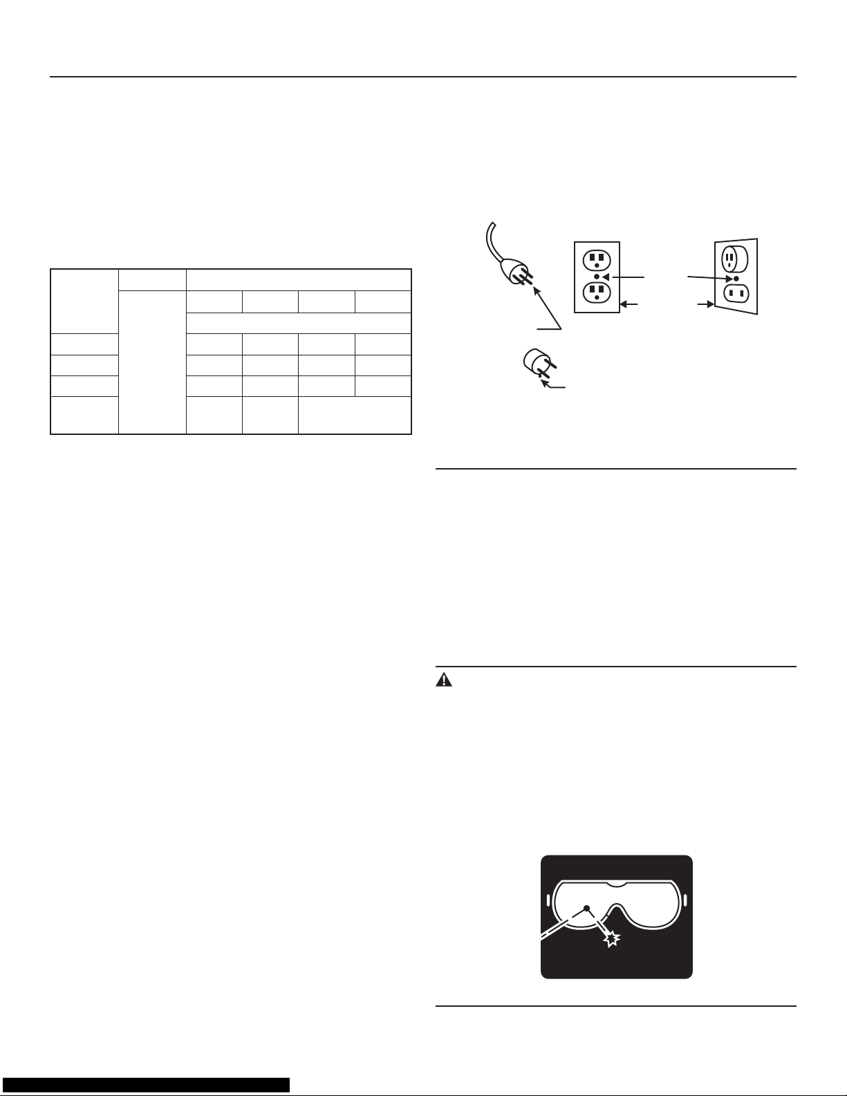
• This tool is intended for use on a circuit with a grounded
outlet (B, Fig. 1). The tool has a grounding plug (A, Fig. 1).
• A temporary adapter (D, Fig. 1) may be used to connect
this plug to a 2-pole receptacle (C, Fig. 1), if a properly
grounded outlet is not available. The green-colored tab
extending from the adapter must be connected to a permanent ground, such as a properly grounded outlet box.
The temporary adapter should be used only until a qualied electrician can install a properly grounded outlet.
Grounding
Pin
Metal
Screw
Cover Of
Grounded
Outlet Box
Adaptor
Grounding
Means
Adaptor Is Not Permitted In Canada
(B)
(A)
(C)
(D)
Fig. 1
Permanently Connected Tools
This tool can be permanently connected to a grounded,
metal, wiring system or to a system that has an equipmentgrounding conductor.
Ground-fault circuit interrupter (GFCI) protection should be
provided on the circuit or outlet to be used for the tile saw.
Receptacles are available having built-in GFCI protection
and may be used for this measure of safety.
Personal Safety
WARNING:
The operation of any power tool can result in foreign
objects being thrown into your eyes, which can result in
severe eye damage. Before beginning power-tool operation, always wear safety goggles or safety glasses with
side shields, and a full-face shield when needed. We
recommend Wide Vision Safety Mask for use over eyeglasses or standard safety glasses with shields. Always
use eye protection, which is marked to comply with
ANSI Z87.1
FORESIGHT IS BETTER
THAN NO SIGHT
WEAR YOUR
SAFETY GLASSES
GENERAL SAFETY INSTRUCTIONS

5
• STAY ALERT, WATCH WHAT YOU ARE DOING, and
USE COMMON SENSE when operating a power tool.
• DO NOT use the tool while tired or under the inuence of
drugs, alcohol, or medication.
• WEAR PROPER APPAREL. Do not wear loose clothing,
gloves, neckties, rings, bracelets, or other jewelry. Pull
back and secure long hair. Non-slip footwear is recommended.
• KEEP YOUR HAIR, CLOTHING, AND GLOVES AWAY
FROM MOVING PARTS.
• REMOVE ADJUSTING KEYS OR WRENCHES. Form a
habit of checking to see that keys and adjusting wrenches
are removed from the tool before turning it on.
• ALWAYS USE SAFETY GLASSES. Everyday glasses
may have impact-resistant lenses, but they are NOT safety glasses.
• USE A DUST OR FACE MASK, if the operation is dusty.
• WEAR HEARING PROTECTION to help prevent hearing
loss.
• NEVER TOUCH THE PINS OF THE ELECTRICAL PLUG
while inserting it into or removing it from an electrical
socket.
• NEVER STAND ON TOOL. Serious injury could occur if
the tool is tipped, or if the cutting tool is unintentionally
contacted.
Tool Safety
• KEEP ALL GUARDS IN PLACE and in working order.
• AVOID ACCIDENTAL STARTING. Be sure the switch is
in the “Off” position before plugging the tool into an electrical outlet.
• DO NOT CARRY TOOLS WITH YOUR FINGER ON THE
SWITCH.
• DO NOT OVER REACH. Keep proper footing and bal-
ance at all times.
• DO NOT FORCE THE TOOL. Use the correct tool and
blade for your application. The correct tool and blade will
do the job better and more safely when used at the rate for
which they are designed.
• DO NOT USE TOOL IF THE SWITCH DOES NOT TURN
IT “ON” OR “OFF.” Any tool that cannot be controlled
with the switch is dangerous and must be repaired.
• DISCONNECT THE TOOL before servicing, when changing accessories (such as cutting blades), or storing the
tool.
• STORE IDLE TOOLS OUT OF THE REACH OF CHILDREN and other untrained people.
• NEVER LEAVE THE TOOL RUNNING UNATTENDED;
turn the power off. Don’t leave the tool until it comes to a
complete stop.
• ALWAYS MAINTAIN TOOLS WITH CARE. Keep cutting
tools sharp and clean. Properly maintained tools with
sharp cutting edges are less likely to bind and are easier to
control. Follow all instructions for lubricating and changing
accessories.
• CHECK FOR DAMAGED PARTS. Before further use of
the tool, a guard or other part that is damaged should be
carefully checked to determine that it will operate properly
and perform its intended function. Check for alignment of
moving parts, binding of moving parts, mounting, and any
other conditions that may affect its operation. A guard or
other part that is damaged should be properly repaired or
replaced.
• USE RECOMMENDED ACCESSORIES. Consult the
product manual for recommended accessories. The use
of improper accessories may increase the risk of personal
injury.
Service Safety
• If any part of this wet-tile/stone saw is missing or should
break, bend, or fail in any way; or should any electrical
component fail to perform properly: ALWAYS shut off the
power switch and remove the plug from the power source,
and have the missing, damaged, or failed part replaced
BEFORE resuming operation.
• When servicing a tool, ALWAYS use only identical replace-
ment parts. Follow instructions in the Maintenance Section on page 35 of this manual. Use of unauthorized parts
or failure to follow Maintenance Instructions may create a
risk of electric shock or injury.
GENERAL SAFETY INSTRUCTIONS
6
SPECIFIC SAFETY INSTRUCTIONS
FOR RIDGID WET TILE/STONE SAW
Safety Instructions for Wet Tile/Stone Saw
WARNING:
Be sure to read and understand all instructions in this
manual before using this Professional Wet Tile/Stone
Saw with Laser Guide, LED Work light and Stand. Failure
to follow all instructions may result in electric shock, fire
and/or serious personal injury
WARNING:
To reduce the risk of mistakes that could cause serious,
permanent injury, do not plug the tile saw into an electrical receptacle until the following steps have been satisfactorily completed:
• COMPLETELY ASSEMBLE THE SAW (See “Assembly”
section, page 13)
• LEARN THE USE AND FUNCTION OF THE ON-OFF
SWITCH, blade guard, laser-adjustment knob, overload
protector, spindle lock, depth-stop-adjustment knob,
depth-adjustment knob, bevel-cut-adjustment knob, universal guide, etc. (See “Getting to Know Your Tile Saw” on
page 24.)
• REVIEW AND UNDERSTAND ALL SAFETY INSTRUC
-
TIONS AND OPERATING PROCEDURES in this manual.
• REVIEW THE MAINTENANCE METHODS for this saw
(See “Maintaining Your Saw” section, page 35).
• NEVER put your ngers or hands in the path of the saw
blade or other cutting tool.
• NEVER REACH BEHIND the cutting tool with either hand
for any reason. Do not reach behind the blade to hold
down the work piece, support the work piece, remove
scraps, or for any other reason.
• NEVER use a hand position where a sudden slip could
cause the ngers or the hand to move into a saw blade.
• FIND AND READ ALL THE WARNING LABELS found
on the tool (shown below).
1. To reduce the risk of electric shock, connect
only to a properly grounded, grounding type
receptacle.
2. To reduce the risk of electric shock, install
only on a circuit protected by a Ground-Fault
Circuit-Interrupter (GFCI).
3. Risk of electric shock - This pump has not
been investigated for use in swimming pool or
marine areas.
PP-399
Submersible Pump
120V 0.23A 60Hz
E204083
63VF
WARNING
CAUTION
IMPEDANCE PROTECTED
Acceptable For Indoor And Outdoor Use
This pump has been evaluated for use with
water only.
FOR YOUR OWN SAFETY, READ INSTRUCTION
MANUAL BEFORE OPERATING SAW
A) WEAR EYE PROTECTION
B) USE SPLASH HOOD FOR EVERY
OPERATION FOR WHICH IT CAN BE USED
C) DISCONNECT SAW BEFORE SERVICING,
WHEN CHANGING CUTTING BLADES, AND
WHEN CLEANING
D) USE TOOL ONLY WITH SMOOTH-EDGE
CUTTING BLADE FREE OF OPENINGS AND
GROOVES
E) REPLACE DAMAGED CUTTING BLADE
BEFORE OPERATING
F) DO NOT EXPOSE TO RAIN OR USE IN
DAMP LOCATIONS
LEE ESTA INSTUCCION MANUALANTES DE USA LA
SIERRA PARA TU BIEN
A) PONE EL PROTECTOR PARA LOS OJOS
B) USA UNA CAPUCHA PARA PROTEGERSE DE
LAS MANCHAS CUANDO USA LA SIERRA
C) DISCONECTA LA SIERRA CUANDO NO ESTA
USADA, O VAA CAMBIAR LA RUEDA DE CORTAR, O
VAA LIMPIARLA
D) CUANDO SE USA, SOLO USA LA PARTE LISA
DE LA RUEDA DE COETAR, Y DEJA LIBRE LA OTEA
PARTE Y LA PANURA
E) ANTES DE USAR LA SIERRA, TIENE QUE
CAMBIAR LA ROTA RUEDA DE CORTAR
F) NO LA DEJES EXPUESTAA LA LLUVIA NI LA
USES EN CONDCIONES MOJADAS
POUR ASSURER VOTRE SECURITE, LISEZ LE
MODE D'EMPLOI AVANT D'UTILISER LE COUPEUR
A) PORTEZ LES LUNETTES DE PROTECTION
B) PORTEZ LA CASQUE DE PROTECTION
PENDANT CHAQUE OPERATION
C) DECONNECTEZ LE MEULE AVANT
L'UTILISATION QUAND ON CHANGE LE MEULE DE
COUPAGE OU LE NETTOIE
D) UTILISEZ SEULEMENT L'OUTIL WITH LE
MEULE A BORD LISSE SANS RAINURE
E) REMPLACEZ LE MEULE AVEC DEGRATS
AVANT L'OPERATION
F) N'EXPOSEZ PAS DANS LA PLUIE OU UTILISE
DANS L'ENVIRONNMENT HUMIDE
MISE EN GARDE
ìST OP/GOî knob must be in the ìST OPî position before operating, moving or transporting
the saw.
For your safety, use the table lock to secure the working table before moving or transporting
the saw.
Líinterrupteur ´ marche/arrÍt ª doit Ítre en position ´ arrÍt ª avant díutiliser , de dÈplacer ou de
transporter la scie.
Pour votre sÈcuritÈ, enclenchez le verrouillage du plateau de travail avant de dÈplacer ou
transporter la scie.
La perilla de STOP/GO debe estar en la posiciÛn de ST OP (PARADA) antes de funcionar, de
mover o de transportar la sierra.
Para su seguridad, utilice la cerradura de la mesa para asegurar la mesa de trabajo antes de
mover o de transportar la sierra.
7
SPECIFIC SAFETY INSTRUCTIONS
FOR RIDGID WET TILE/STONE SAW
The labels on your tool may include the following symbols:
V . . . . . . . . . . . Volts
A . . . . . . . . . . . Amperes
Hz . . . . . . . . . . Hertz
W . . . . . . . . . . . Watts
~
. . . . . . . . . . Alternating Current
min . . . . . . . . . . Minutes
n
o . . . . . . . . . . No-load speed
RPM . . . . . . . . Revolutions or reciprocation per minute
. . . . . . . . . . Indicates danger, warning or caution.
It means ATTENTION! Your safety is
involved.
WARNING:
Use of this tool can generate dust-containing chemicals
known to the state of California to cause cancer, birth
defects, or other reproductive harm. Some examples of
these chemicals are:
• Lead from lead-based paints.
• Crystalline silica from bricks, cement, and other
masonry products.
• Arsenic and chromium from chemically treated lumber.
Your risk from these exposures varies, depending upon
how often do this type of work. To reduce your exposure
to these chemicals:
Work in a well-ventilated area.
Work with approved safety equipment, such as those
dust masks that are specially designed to filter out microscopic particles.
Avoid prolonged contact with dust from power sanding,
sawing, grinding, drilling, and other construction activities. Wear protective clothing and wash exposed areas
with soap and water.
Allowing dust to get into your mouth or eyes or to lie on
the skin may promote absorption of harmful chemicals.
Use of accessories that are not recommended for use
with this tool may create hazardous conditions.
• DIRECTION OF FEED: Always feed work into the blade
against the rotational direction of the blade.
• LET THE BLADE COME TO A COMPLETE STOP before
removing any jammed or off-cut material from around the
blade area.
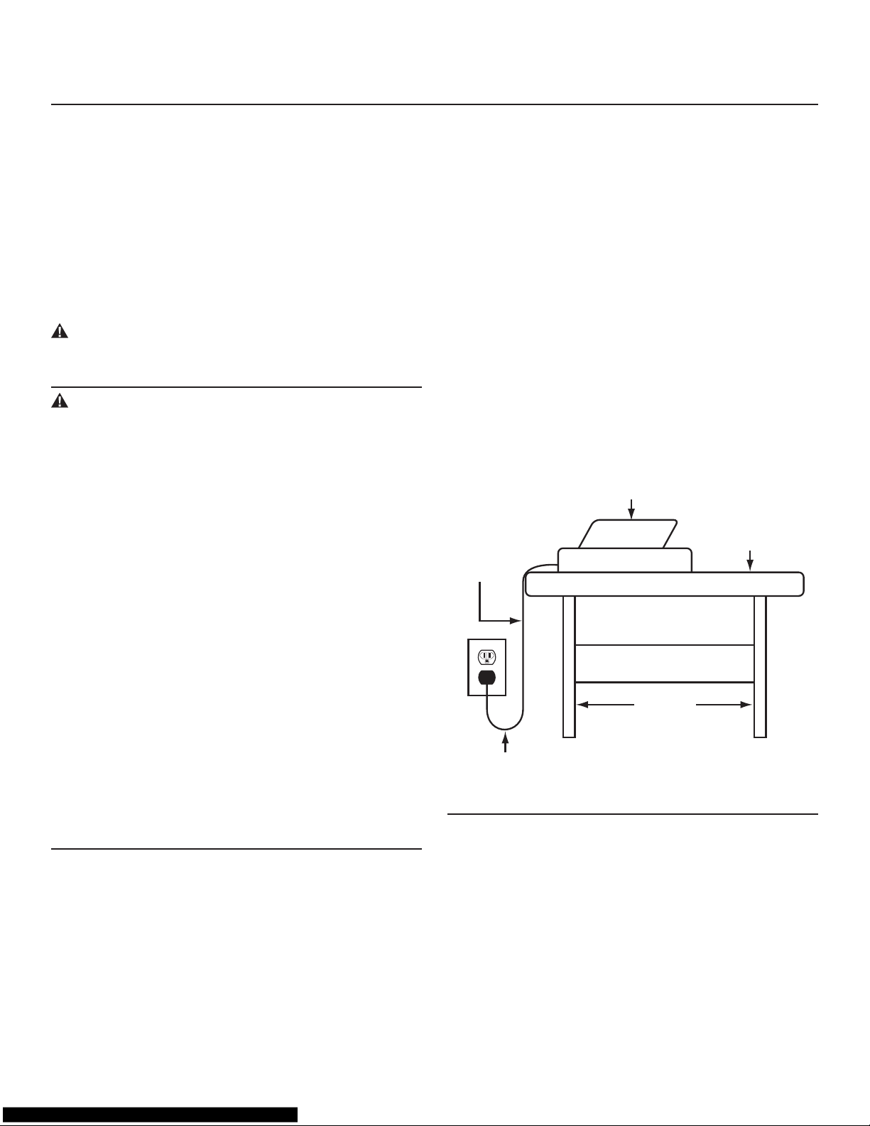
• POSITION OF TILE SAW: To avoid the possibility of the
appliance plug or receptacle getting wet, position the tile
saw to one side of a wall-mounted receptacle. The user
should arrange a “drip loop” in the cord connecting the
saw to a receptacle. (Fig. 2)
The “drip loop” is a section of the cord that hangs below the
level of the receptacle or below the connector, if an extension cord is used, to keep the water that travels along the
cord from coming into contact with the receptacle. (Fig. 2)
If the plug or receptacle does get wet, DON’T unplug the
cord. Disconnect the fuse or circuit breaker that supplies
power to the tool. Then unplug the tool and examine the
receptacle for water. Do not use the receptacle until it is
completely dry.
Power
Supply
Cord
Tile Saw
Drip Loop
Water Tray
Tile Saw
Support
Fig. 2

8
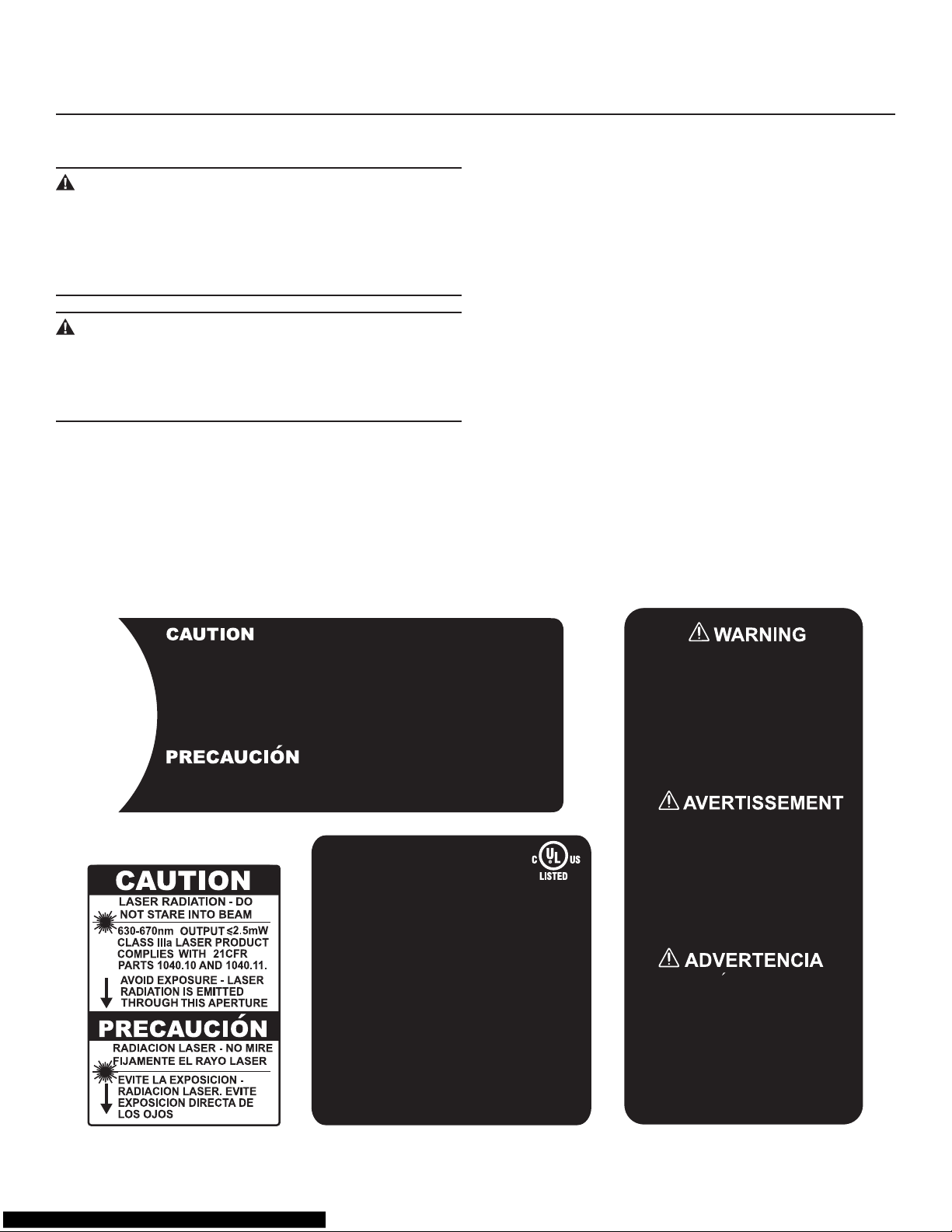
Safety Instructions for Laser
This saw has a built-in laser light. The laser is class IIIa and
emits output power of a maximum 2.5mW and 630~670nm
wavelengths. The laser doesn’t normally present an optical
hazard.
CAUTION
The following label is on your saw. It indicates where the
laser light is emitted by the saw.
CAUTION:
Avoid exposure. Laser radiation is emitted through this
aperture.
CAUTION:
The use of controls or adjustments or the performance
of procedures other than those directed in this manual
may result in hazardous radiation exposure.
WARNING:
Laser radiation. Avoid direct eye exposure. Do not stare
into the beam. Turn the laser on only when the tool is
operated.
Be sure to read and understand all instructions. Always
follow the following safety rules when using this saw:
NEVER aim the beam at any person or at any object
other than the work piece.
DO NOT look directly into the laser-beam output aperture during operation. The laser beam can be harmful to
the eyes.
ALWAYS keep the laser out of the reach of children. The
laser on the saw is not a toy.
Using optical instruments with this product will increase
eye hazard.
DON’T ATTEMPT TO REPAIR OR DISASSEMBLE the
laser. If unqualified persons attempt to repair this product, serious injury may result. Any repair required on this
laser product should be performed by authorized service-center personnel.
SPECIFIC SAFETY INSTRUCTIONS
FOR RIDGID WET TILE/STONE SAW
9
Arbor
The shaft on which a cutting tool is mounted.
Bevel Cut
A cutting operation made across the width of the work piece
in which the cut is not perpendicular to the surface of the
work piece.
Flat Angle Cut
An angle-cutting operation made through the face of work
piece: The cut is perpendicular to the surface of the work
piece and is at an angle other than 90° to the edge of the
tile.
Freehand
Performing a cut without using a rip fence (guide), xture,
hold-down, or other proper device to prevent the work piece
from twisting during the cutting operation. Never cut freehand with this tool.
Off-Cut
The portion of the work piece that has been cut off.
Plunge Cut
A cutting operation in which the rotating blade is lowered
onto the work piece.
Revolutions Per Minute (RPM)
The number of turns completed by a spinning object in one
minute.
Straight Cut
A cutting operation parallel to the one straight edge of the
work piece.
Work Piece
The item on which the cutting operation is being performed.
The surfaces of a work piece are commonly referred to as
faces, ends, and edges.
Through-Sawing
Any cut that completely severs the work piece.
GLOSSARY OF TERMS
Power Supply And Motor Specifications
WARNING:
To reduce the risk of electrical hazards, fire hazards, or
damage to the tool, use a ground-fault circuit interrupter. If the power cord is worn, cut, or damaged in any
way, replaced it immediately to reduce the risk of shock
or fire
The motor is wired for operation on 120v AC, 60 Hz service.
Rate H.P. 2-1/2
Voltage 120V
Amperes 15
Hertz (Cycles) 60
Phase Single
RPM 4
200
Table 2
General Electrical Connections
WARNING:
To reduce the risk of electrocution:
1. Use only identical replacement parts when servicing. Servicing should be performed only by a qualified, service technician.
2. Do not use in rain or where the floor is wet. This tool
is intended for indoor, residential use only.
WARNING:
Do not permit fingers to touch the terminals of plug when
installing or removing the plug to or from the outlet.
MOTOR SPECIFICATIONS AND ELECTRICAL REQUIREMENTS
10
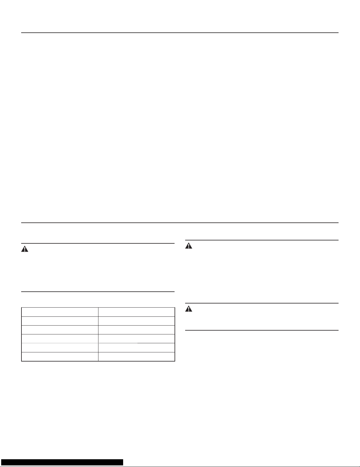
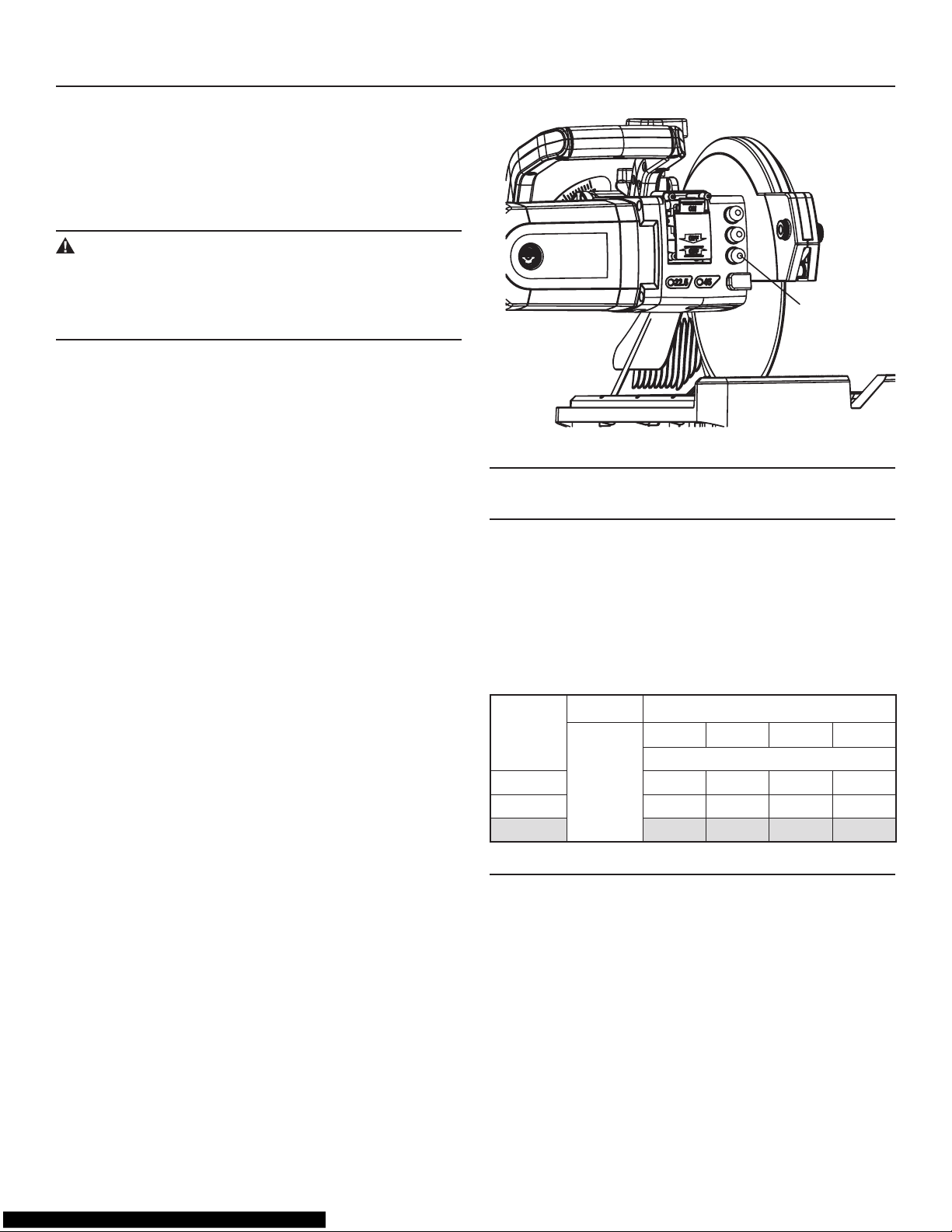
MOTOR OVERLOAD PROTECTOR
Your saw is equipped with a manual-reset, motor-overload
protector. The overload protector is designed to stop the
current to the saw when the motor current exceeds a safe
level, when the motor is overloaded, or when a low-voltage
condition exists.
WARNING:
If the motor-overload protector stops the saw motor,
immediately turn the saw switch to “OFF” and then allow
the motor to cool. This will reduce the risk of the saw
starting unexpectedly and causing harm or injury.
When the motor-overload protector stops the motor:
1. After cooling to a safe operating temperature, the over-
load protector can be reset by pressing the overloadprotector switch on the side of the motor. (See Fig. 3)
2. As soon as the overload-protector switch is reset, the
saw may be started and operated normally.
3. Frequent “tripping” of the overload protector may occur
under the following conditions:
— Motor is overloaded: Overloading can occur if you
feed the material to be cut too rapidly, or if saw blade
is misaligned.
— Low voltage: The saw motor is designed to operate
on the voltage specied on the motor nameplate.
Normal loads will be safely handled on voltages not
more than 10% above or below the nameplate voltage. Heavy loads, however, require that the voltage
at the motor terminals equals the voltage specied
on nameplate.
4. Most motor troubles may be traced to loose or incorrect
connections, overloading, reduced input voltage (such
as small-size wire in the supply circuit), or to an overly
long supply-circuit wire. Always check the connections,
the load, and the supply circuit whenever the motor fails
to perform satisfactorily.
MOTOR SPECIFICATIONS AND ELECTRICAL REQUIREMENTS
Overload
Protector
Switch
Fig. 3
Wire Sizes
NOTE:
Use proper extension cord. Make sure that the extension
cord is in good condition and is heavy enough to carry the
current your tool will draw. This tool draws 15 amps. Table 1
shows the correct size to use. An undersized cord will cause
a drop in line voltage resulting in loss of power and overheating. If in doubt, use the next heavier gauge: the smaller
the gauge number, the heavier the cord.
Ampere
Rating
Volts Total Length of Cord in Feet
1
20V~
25 ft. 50 ft. 100 ft. 150 ft.
A. W. G.
6~10 18 16 14 1
2
10~12
16 16 14 12
12~16 14 1
2 — —
Table 3
11
UNPACKING AND CHECKING CONTENTS
Unpacking
The WTS2000L tile saw comes in one carton.
Separate all the parts from the packing materials. Refer to
the “List of Loose Parts” below and “List of Main Parts” on
page 12 to make certain that all the items are accounted for
before discarding any packing material. Call RIDGID® Service Center if any parts are damaged or missing.
WARNING:
If any parts are missing, do not attempt to assemble the
tile saw, plug in the power cord, or turn on the switch
until the missing parts are obtained and are installed
correctly.
NOTE: Before beginning assembly
• Check the “List of Loose Parts” and “List of Main Parts” to
make certain that all the items are accounted for. Check
that all the parts are included. If you are missing any part,
do not assemble the saw.
• Sometimes, small parts can get lost in packaging material.
Do not throw away any packaging until the saw is fully assembled. Check the packaging for missing parts before
contacting RIDGID.
• A complete parts list is at the end of the manual. Use this
list to identify the part number of the missing part.
WARNING:
For your own safety, never connect a plug to a power
source outlet until all assembly steps are complete and
you have read and understand the safety and operating
instructions.
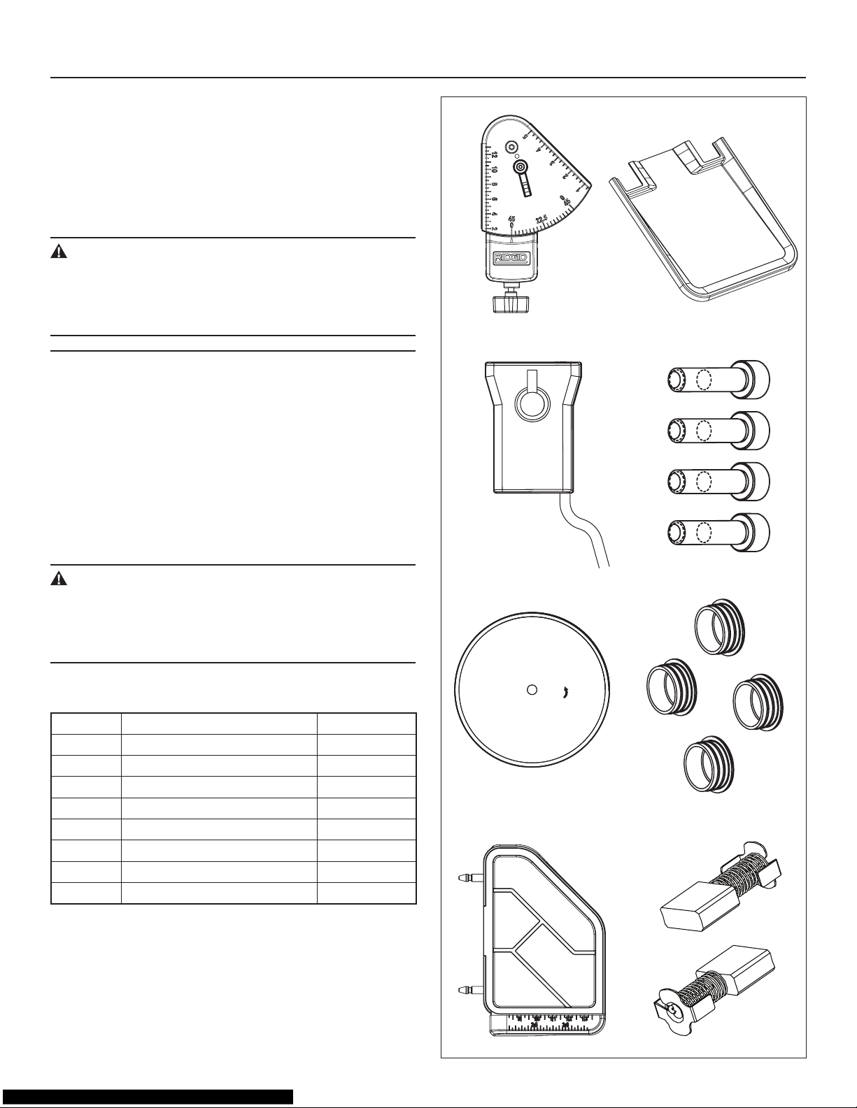
List of Loose Parts
Item Part Name QuaNtIty
A Universal Guide 1
B Water Pump 1
C Saw Blade 1
D Extension Table 1
E Extension Water Tray 1
F Bolt 4
G Bolt Cover 4
H Carbon Brush
2
A E
B
F
C
G
D
H
12
UNPACKING AND CHECKING CONTENTS
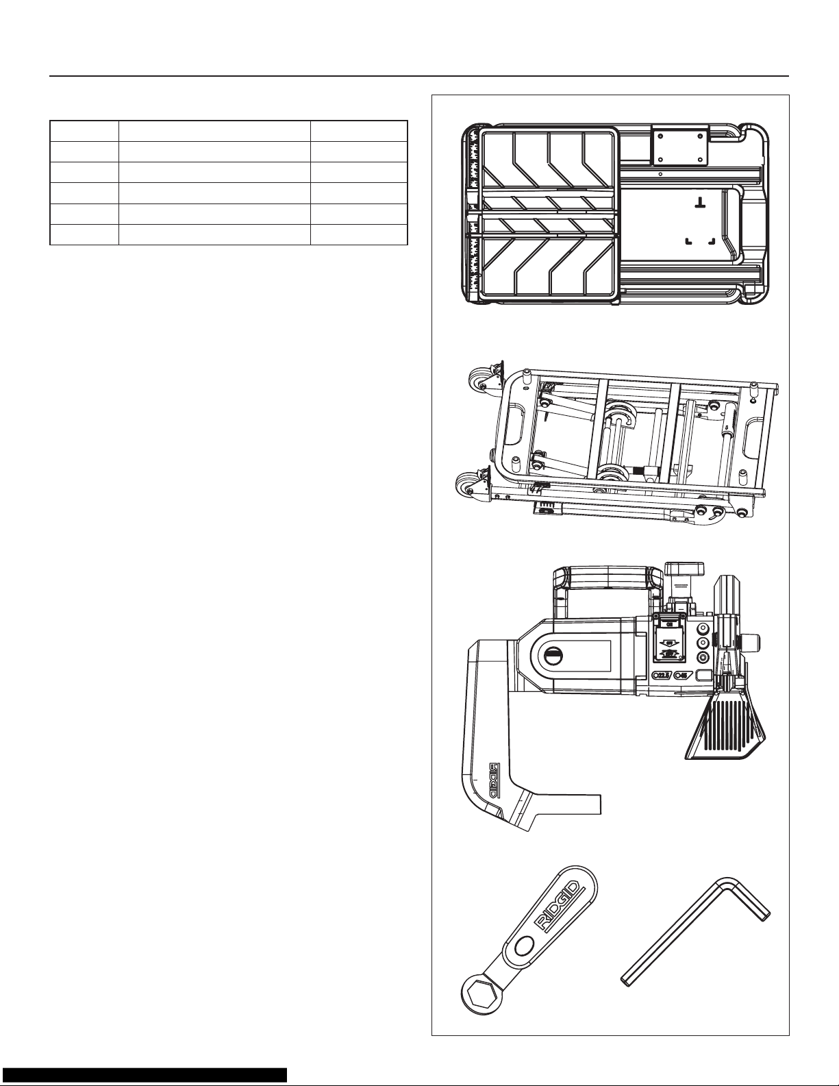
List of Main Parts
Item Part Name QuaNtIty
I Frame Assembly & Water Tray 1
J Stand 1
K Motor Assembly 1
L Nut Wrench 1
M Hex Wrench 1
*
+
,
L M
13
ASSEMBLY
In addition to the nut wrench and hex wrench supplied with
your saw, no tools are needed for assembly.
Stand Set-Up
CAUTION:
To avoid serious injury when lifting the saw, bend your
knees and lift with your legs, not with your back.
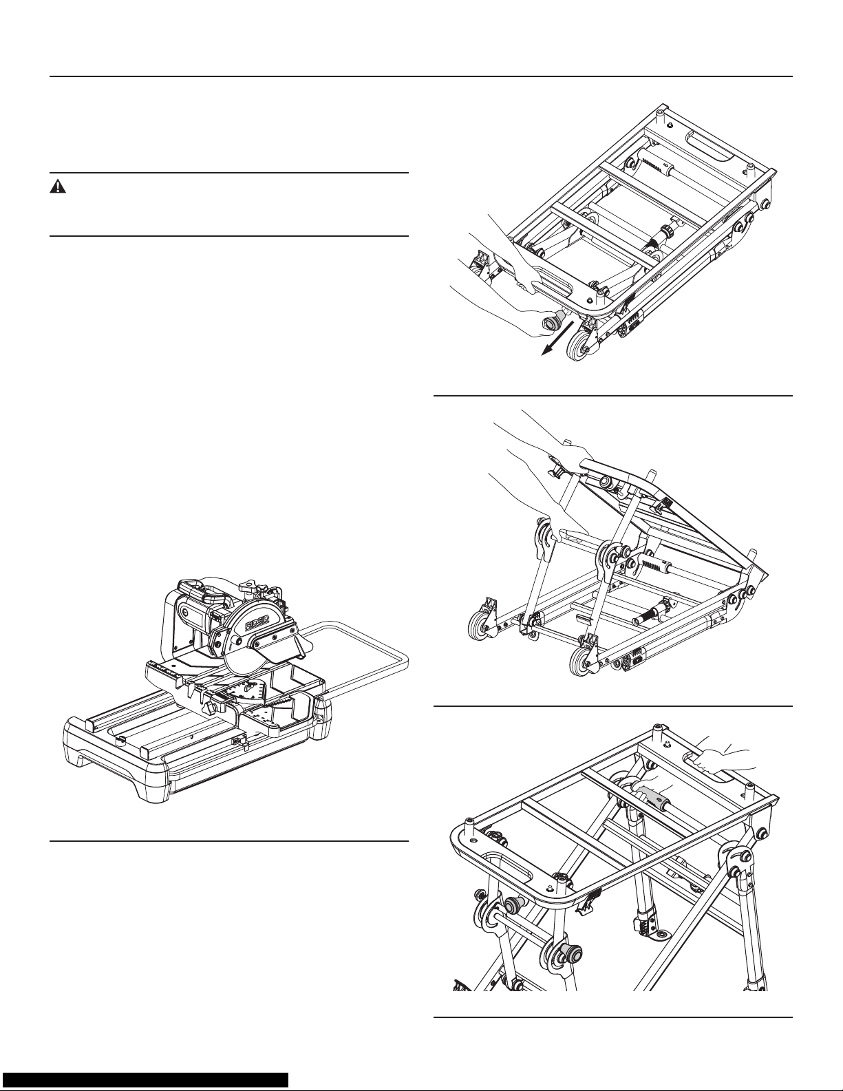
The saw can be placed on a at surface for cutting operations without using the stand. (Fig. 4)
When using the stand, observe the following instructions:
To Open the Stand:
1. Place the folded stand on a at surface, as shown in
Fig. 5.
2. Pull out the lock knob, then lift the handle (Fig. 5).
3. Continuing to lift the handle, pull the crossbar out until
you hear the legs lock in place (Fig. 6).
4. On the opposite end of the stand, locate the handle and
the orange lock sleeve on the crossbar, and note the
arrow on the lock sleeve. Lift the handle and move the
lock sleeve in the direction of the arrow on the sleeve.
Allow the legs to fall (Fig .7), and then release the sleeve.
Hold the lift handle, and pull the lower crossbar until you
hear the legs lock into place.
Fig. 4
Fig. 5
Fig. 6
Fig. 7
14
ASSEMBLY
Stand Set-Up, continued
5. Tighten the locking nut (Fig 8). Make sure all connec-
tions are rm and the stand is steady.
6. The stand anchors located on the two shorter legs (Fig.
9) may be used to attach the stand to the oor with
screws (not supplied).
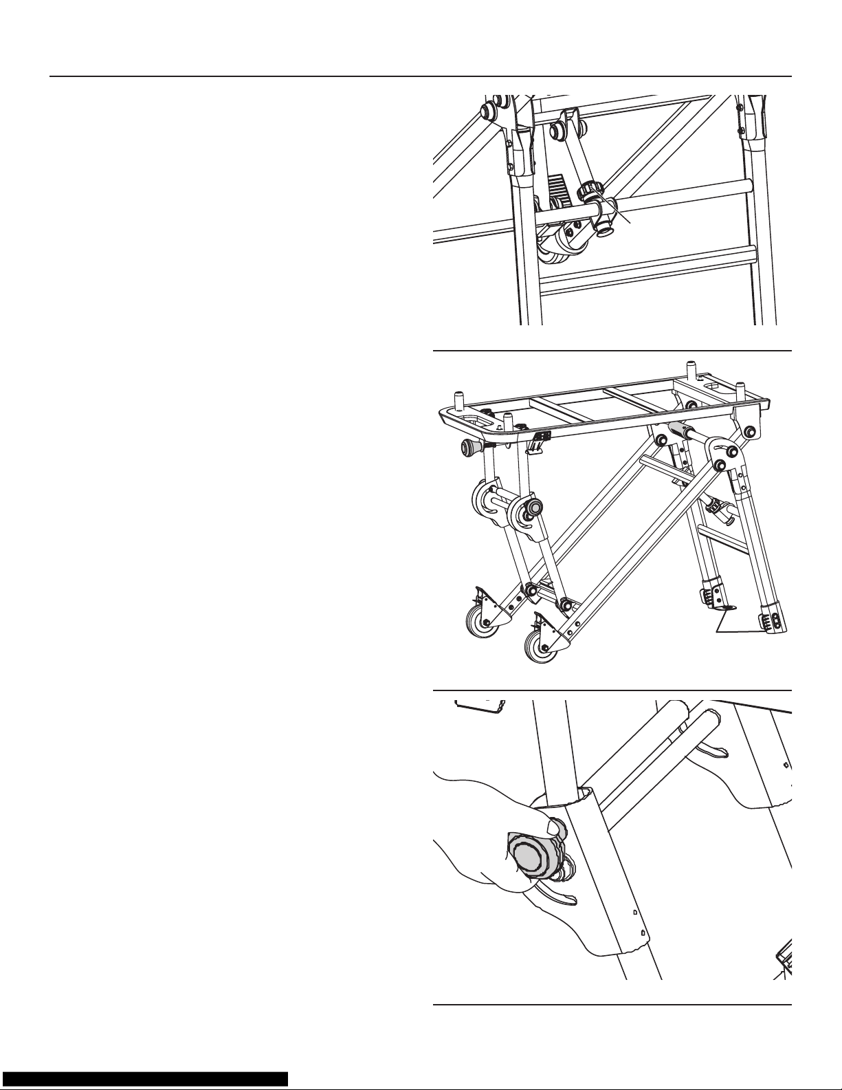
Closing the Stand
From the side of the stand with two wheels, rst pull out the
orange knob at the end of the crossbar, as shown in Fig. 10,
then reverse the steps described in “To Open the Stand,”
page 13.
Locking Nut
Fig. 8
Stand Anchors
Fig. 9
Fig. 10
 Loading...