


OPERATOR'S MANUAL
6-1/8 in. JOINTER/PLANER
JP06101
Your Jointer/Planer has been engineered and manufactured to RIDGID’s high standard for dependability, ease of operation, and operator safety. When properly cared for, it will give you years of rugged, trouble-free performance.
WARNING:
To reduce the risk of injury, the user must read and understand the operator's manual before using this product.
Thank you for buying a RIDGID product.
SAVE THIS MANUAL FOR FUTURE REFERENCE

TABLE OF CONTENTS |
|
n Introduction........................................................................................................................................................................ |
2 |
n General Safety Rules..................................................................................................................................................... |
3-4 |
n Specific Safety Rules......................................................................................................................................................... |
5 |
n Symbols......................................................................................................................................................................... |
6-7 |
n Electrical ........................................................................................................................................................................ |
8-9 |
n Glossary of Terms............................................................................................................................................................ |
10 |
n Features..................................................................................................................................................................... |
11-12 |
n Tools Needed................................................................................................................................................................... |
12 |
n Loose Parts................................................................................................................................................................ |
13-14 |
n Assembly ................................................................................................................................................................... |
14-20 |
n Operation................................................................................................................................................................... |
21-28 |
n Adjustments............................................................................................................................................................... |
29-31 |
n Maintenance.............................................................................................................................................................. |
32-33 |
n Accessories ..................................................................................................................................................................... |
34 |
n Troubleshooting......................................................................................................................................................... |
34-35 |
n Warranty .......................................................................................................................................................................... |
39 |
n Customer Service Information......................................................................................................................................... |
40 |
INTRODUCTION |
|
This tool has many features for making its use more pleasant and enjoyable. Safety, performance, and dependability have been given top priority in the design of this product making it easy to maintain and operate.
2

GENERAL SAFETY RULES
WARNING:
Read and understand all instructions. Failure to follow all instructions listed below, may result in electric shock, fire and/or serious personal injury.
READ ALL INSTRUCTIONS
n KNOW YOUR POWER TOOL. Read the operator's manual carefully. Learn the applications and limitations as well as specific potential hazards related to this tool.
n GUARD AGAINST ELECTRICAL SHOCK BY PREVENTING BODY CONTACT WITH GROUNDED SURFACES. For example: pipes, radiators, ranges, refrigerator enclosures.
nKEEP GUARDS IN PLACE and in working order.
nREMOVE ADJUSTING KEYS AND WRENCHES. Form habit of checking to see keys and adjusting wrenches are removed from tool before turning it on.
nKEEP THE WORK AREA CLEAN. Cluttered work areas and work benches invite accidents. DO NOT leave tools or pieces of wood on the tool while it is in operation.
nDO NOT USE IN DANGEROUS ENVIRONMENTS. Do not use power tools in damp or wet locations or expose them to rain. Keep the work area well lit.
nKEEP CHILDREN AND VISITORS AWAY. All visitors should wear safety glasses and be kept a safe distance from work area. Do not let visitors contact tool or extension cord while operating.
nMAKE WORKSHOP CHILDPROOF with padlocks, master switches, or by removing starter keys.
nDON’T FORCE THE TOOL. It will do the job better and safer at the rate for which it was designed.
nUSE THE RIGHT TOOL. Do not force the tool or attachment to do a job for which it was not designed.
nUSE THE PROPER EXTENSION CORD. Make sure your extension cord is in good condition. Use only a cord heavy enough to carry the current your product will draw. An undersized cord will cause a drop in line voltage resulting in loss of power and overheating. A wire gauge size (A.W.G.) of at least 14 is recommended for an extension cord 25 feet or less in length. If in doubt, use the next heavier gauge. The smaller the gauge number, the heavier the cord.
nDRESS PROPERLY. Do not wear loose clothing, neckties, or jewelry that can get caught and draw you into moving parts. Rubber gloves and nonslip footwear are recommended when working outdoors. Also wear protective hair covering to contain long hair.
nALWAYS WEAR SAFETY GLASSES WITH SIDE SHIELDS. Everyday eyeglasses have only impact-resis- tant lenses, they are NOT safety glasses.
nSECURE WORK. Use clamps or a vise to hold work when practical, it is safer than using your hand and frees both hands to operate the tool.
nDO NOT OVERREACH. Keep proper footing and balance at all times.
nMAINTAIN TOOLS WITH CARE. Keep tools sharp and clean for best and safest performance. Follow instructions for lubricating and changing accessories.
nDISCONNECT TOOLS. When not in use, before servicing, or when changing attachments, blades, bits, cutters, etc., all tools should be disconnected from power source.
nAVOID ACCIDENTAL STARTING. Be sure switch is off when plugging in any tool.
nUSE RECOMMENDED ACCESSORIES. Consult the operator’s manual for recommended accessories. The use of improper accessories may result in injury.
nNEVER STAND ON TOOL. Serious injury could occur if the tool is tipped.
nCHECK DAMAGED PARTS. Before further use of the tool, a guard or other part that is damaged should be carefully checked to determine that it will operate properly and perform its intended function. Check for alignment of moving parts, binding of moving parts, breakage of parts, mounting and any other conditions that may affect its operation. A guard or other part that is damaged must be properly repaired or replaced by an authorized service center to avoid risk of personal injury.
nUSE THE RIGHT DIRECTION OF FEED. Feed work into a blade, cutter, or sanding spindle against the direction or rotation of the blade, cutter, or sanding spindle only.
nNEVER LEAVE TOOL RUNNING UNATTENDED. TURN THE POWER OFF. Don’t leave tool until it comes to a complete stop.
nPROTECT YOUR LUNGS. Wear a face or dust mask if the cutting operation is dusty.
nPROTECT YOUR HEARING. Wear hearing protection during extended periods of operation.
nDO NOT ABUSE CORD. Never carry tool by the cord or yank it to disconnect from receptacle. Keep cord from heat, oil, and sharp edges.
nUSE OUTDOOR EXTENSION CORDS. When tool is used outdoors, use only extension cords with approved ground connection that are intended for use outdoors and so marked.
nKEEP BLADES CLEAN, SHARP, AND WITH SUFFICIENT SET. Sharp blades minimize stalling and kickback.
nNEVER USE IN AN EXPLOSIVE ATMOSPHERE.
Normal sparking of the motor could ignite fumes.
nINSPECT TOOL CORDS PERIODICALLY. If damaged, have repaired by a qualified service technician at an authorized service facility. The conductor with insulation having an outer surface that is green with or without yellow stripes is the equipment-grounding conductor. If repair or replacement of the electric cord or plug is necessary, do not connect the equipment-grounding conductor to a live terminal. Repair or replace a damaged or worn cord immediately. Stay constantly aware of cord location and keep it well away from the rotating blade.
3

GENERAL SAFETY RULES
nINSPECT EXTENSION CORDS PERIODICALLY and replace if damaged.
nKEEP TOOL DRY, CLEAN, AND FREE FROM OIL AND GREASE. Always use a clean cloth when cleaning. Never use brake fluids, gasoline, petroleum-based products, or any solvents to clean tool.
nSTAY ALERT AND EXERCISE CONTROL. Watch what you are doing and use common sense. Do not operate tool when you are tired. Do not rush.
nDO NOT USE TOOL IF SWITCH DOES NOT TURN IT ON AND OFF. Have defective switches replaced by an authorized service center.
nINSPECT FOR AND REMOVE ALL NAILS FROM LUMBER BEFORE USING THIS TOOL. Following this rule will reduce the risk of serious personal injury.
nNEVER START A TOOL WHEN ANY ROTATING COMPONENT IS IN CONTACT WITH THE WORKPIECE.
nDO NOT OPERATE A TOOL WHILE UNDER THE INFLUENCE OF DRUGS, ALCOHOL, OR ANY MEDICATION.
nWHEN SERVICING use only identical replacement parts. Use of any other parts may create a hazard or cause product damage.
nUSE ONLY RECOMMENDED ACCESSORIES listed in this manual or addendums. Use of accessories that are not listed may cause the risk of personal injury. Instructions for safe use of accessories are included with the accessory.
nDOUBLE CHECK ALL SETUPS. Make sure the spindle or sanding belt assembly is tight and not making contact with sander or workpiece before connecting to power supply.
4

SPECIFIC SAFETY RULES
nPROTECT YOUR LUNGS. Wear a face or dust mask if the cutting operation is dusty.
nPROTECT YOUR HEARING. Wear hearing protection during extended periods of operation.
nINSPECT TOOL CORDS PERIODICALLY AND, IF DAMAGED, HAVE REPAIRED AT YOUR NEAREST AUTHORIZEDSERVICECENTER.CONSTANTLYSTAY AWARE OF CORD LOCATION. Following this rule will reduce the risk of electric shock or fire.
nINSPECT FOR AND REMOVE ALL NAILS FROM LUMBER BEFORE USING THIS TOOL. Following this rule will reduce the risk of serious personal injury.
nSAVE THESE INSTRUCTIONS. Refer to them frequently and use them to instruct others who may use this tool. If you loan someone this tool, loan them these instructions also.
nSMALL OR THIN WORKPIECES CAN KICKBACK WHEN THEY TIP OVER ON THE TABLES OR INTO THE CUTTER HEAD. To reduce the risk of cutter head contactorworkpiecekickback:Neverjoint,planeorbevel workpieces shorter than 12 in.
nWHEN JOINTING never joint workpieces less than 3/4 in. wide or 1/4 in. thick.
nALWAYSUSEPUSHBLOCKS/PUSHSTICKwhenjointing or beveling wood narrower than 3 in.
nWHEN RABBETING always make cuts in 1/8 in. increments or less.
n NEVER PLANE WOOD NARROWER OR THINNER THAN 3/4 IN.
nALWAYSUSEPUSHBLOCKS/PUSHSTICKwhenplaning.
nNEVER perform any operation "freehand" which means using only your hands to support or guide the workpiece. Always use either the rip fence or miter fence to position and guide the work.
nMAKE SURE THERE’S NO DEBRIS between the workpiece and either the fence or table top.
nALWAYS USE A STABLE WORK SUPPORT WHEN JOINTING OR PLANING LONG WORKPIECES. Never use another person as additional support or to help feed, support or pull the workpiece in any operation.
nNEVER CUT more than one workpiece at a time.
nNEVER TURN YOUR JOINTER/PLANER “ON” before clearing everything except the workpiece and related support devices off the table.
nAVOID AWKWARD OPERATIONS AND HAND POSITIONS where a sudden slip could cause your hand to move into the cutter head. Never pass either hand over the cutter head during any operation.
nSAVETHESEINSTRUCTIONS.Refertothemfrequently and use to instruct other users. If you loan someone this tool, loan them these instructions also.
 WARNING:
Some dust created by power sanding, sawing, grinding, drilling, and other construction activities contains chemicals known to cause cancer, birth defects or other reproductive harm. Some examples of these chemicals are:
•lead from lead-based paints,
•crystalline silica from bricks and cement and other masonry products, and
•arsenic and chromium from chemically-treated lumber.
Your risk from these exposures varies, depending on how often you do this type of work. To reduce your exposure to these chemicals: work in a well ventilated area, and work with approved safety equipment, such as those dust masks that are specially designed to filter out microscopic particles.
5

SYMBOLS
Some of the following symbols may be used on this tool. Please study them and learn their meaning. Proper interpretation of these symbols will allow you to operate the tool better and safer.
SYMBOL |
NAME |
DESIGNATION/EXPLANATION |
V |
Volts |
Voltage |
A |
Amperes |
Current |
Hz |
Hertz |
Frequency (cycles per second) |
W |
Watt |
Power |
min |
Minutes |
Time |
|
Alternating Current |
Type of current |
|
Direct Current |
Type or a characteristic of current |
no |
No Load Speed |
Rotational speed, at no load |
|
Class II Construction |
Double-insulated construction |
.../min |
Per Minute |
Revolutions, strokes, surface speed, orbits etc., per minute |
|
Wet Conditions Alert |
Do not expose to rain or use in damp locations. |
|
Read The Operator’s Manual |
To reduce the risk of injury, user must read and understand |
|
operator’s manual before using this product. |
|
|
|
|
|
Eye Protection |
Always wear safety goggles or safety glasses with side shields |
|
and a full face shield when operating this product. |
|
|
|
|
|
Safety Alert |
Precautions that involve your safety. |
|
No Hands Symbol |
Failure to keep your hands away from the blade will result in |
|
serious personal injury. |
|
|
|
|
|
No Hands Symbol |
Failure to keep your hands away from the blade will result in |
|
serious personal injury. |
|
|
|
|
|
No Hands Symbol |
Failure to keep your hands away from the blade will result in |
|
serious personal injury. |
|
|
|
|
|
No Hands Symbol |
Failure to keep your hands away from the blade will result in |
|
serious personal injury. |
|
|
|
|
|
Hot Surface |
To reduce the risk of injury or damage, avoid contact with |
|
any hot surface. |
|
|
|
6

SYMBOLS
The following signal words and meanings are intended to explain the levels of risk associated with this product.
SYMBOL SIGNAL |
MEANING |
DANGER: Indicates an imminently hazardous situation, which, if not avoided, will result in death or serious injury.
WARNING: Indicates a potentially hazardous situation, which, if not avoided, could result in death or serious injury.
CAUTION: Indicates a potentially hazardous situation, which, if not avoided, may result in minor or moderate injury.
CAUTION: (Without Safety Alert Symbol) Indicates a situation that may result in property damage.
SERVICE
Servicing requires extreme care and knowledge and should be performed only by a qualified service technician. For service we suggest you return the product to your nearest
AUTHORIZED SERVICE CENTER for repair. When servicing, use only identical replacement parts.
WARNING:
To avoid serious personal injury, do not attempt to use this product until you read thoroughly and understand completely the operator’s manual. Save this operator’s manual and review frequently for continuing safe operation and instructing others who may use this product.
 WARNING:
The operation of any power tool can result in foreign objects being thrown into your eyes, which can result in severe eye damage. Before beginning power tool operation, always wear safety goggles or safety glasses with side shields and a full face shield when needed. We recommend Wide Vision Safety Mask for use over eyeglasses or standard safety glasses with side shields. Always use eye protection which is marked to comply with ANSI Z87.1.
SAVE THESE INSTRUCTIONS
7
ELECTRICAL
EXTENSION CORDS
Use only 3-wire extension cords that have 3-prong grounding plugs and 3-pole receptacles that accept the tool's plug. When using a power tool at a considerable distance from the power source, use an extension cord heavy enough to carry the current that the tool will draw. An undersized extension cord will cause a drop in line voltage, resulting in a loss of power and causing the motor to overheat. Use the chart provided below to determine the minimum wire size required in an extension cord. Only round jacketed cords listed by Underwriter's Laboratories (UL) should be used.
**Ampere rating (on tool faceplate)
|
0-2.0 |
2.1-3.4 |
3.5-5.0 5.1-7.0 |
7.1-12.0 |
12.1-16.0 |
|
Cord Length |
Wire Size (A.W.G.) |
|
|
|||
|
|
|
|
|
|
|
25' |
16 |
16 |
16 |
16 |
14 |
14 |
|
|
|
|
|
|
|
50' |
16 |
16 |
16 |
14 |
14 |
12 |
|
|
|
|
|
|
|
100' |
16 |
16 |
14 |
12 |
10 |
— |
**Used on 12 gauge - 20 amp circuit.
NOTE: AWG = American Wire Gauge
When working with the tool outdoors, use an extension cord that is designed for outside use. This is indicated by the letters “WA” on the cord's jacket.
Before using an extension cord, inspect it for loose or exposed wires and cut or worn insulation.
WARNING:
Keep the extension cord clear of the working area. Position the cord so that it will not get caught on lumber, tools or other obstructions while you are working with a power tool. Failure to do so can result in serious personal injury.
SPEED AND WIRING
The no-load speed of this tool is approximately 3,450/min. This speed is not constant and decreases under a load or with lower voltage. For voltage, the wiring in a shop is as important as the motor’s horsepower rating. A line intended only for lights cannot properly carry a power tool motor. Wire that is heavy enough for a short distance will be too light for a greater distance. A line that can support one power tool may not be able to support two or three tools.
GROUNDING INSTRUCTIONS
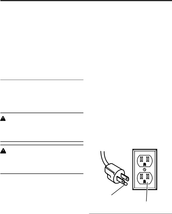
Intheeventofamalfunction or breakdown, grounding provides a path of least resistance for electric current to reduce the risk of electric shock. This tool is equipped with an electric cord having an equipment-groundIng conductor and a grounding plug. The plug must be plugged into a matching outlet that is properly installed and grounded in accordance with all local codes and ordinances.
Do not modify the plug provided. If it will not fit the outlet, have the proper outlet installed by a qualified electrician. Improper connection of the equipment-grounding conductor can result in a risk of electric shock. The conductor with insulation having an outer surface that is green with or without yellow stripes is the equipment-grounding conductor. If repair or replacement of the electric cord or plug is necessary, do not connect the equipmentgrounding conductor to a live terminal.
Check with a qualified electrician or service personnel if the grounding instructions are not completely understood, or if in doubt as to whether the tool is properly grounded.
Repair or replace a damaged or worn cord immediately. This tool is intended for use on a circuit that has an outlet like the one shown in figure 1. It also has a grounding pin like the one shown.
WARNING:
Check extension cords before each use. If damaged replace immediately. Never use tool with a damaged cord since touching the damaged area could cause electrical shock resulting in serious injury.
ELECTRICAL CONNECTION
This tool is powered by a precision built electric motor. It should be connected to a power supply that is 120 volts, 60 Hz, AC only (normal household current). Do not operate this tool on direct current (DC). A substantial voltage drop will cause a loss of power and the motor will overheat. If the saw does not operate when plugged into an outlet, double check the power supply.
GROUNDING
PIN
120 V GROUNDED
OUTLET
Fig. 1
8
ELECTRICAL
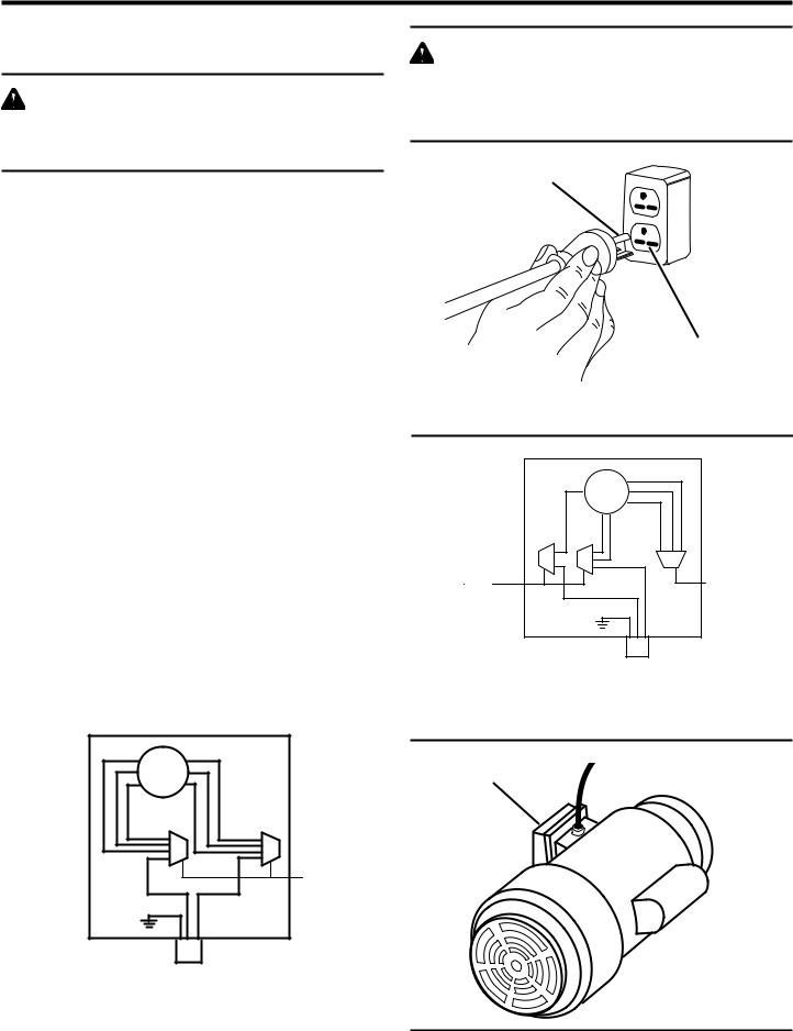
CHANGING MOTOR VOLTAGE
See Figures 2 - 5.
WARNING:
Electric shock can kill. To reduce the risk of serious personal injury, never connect plug to power source until all assembly steps are completed.
NOTE: The jointer/planer is prewired at the factory for 120 volts, 60 Hz. Use the following procedures to change motor voltage from 120 volts to 240 volts.
nUnplug the jointer/planer.
nLocated on the side of the motor is the junction box. Remove the phillips screw at the back of the junction box then lift off the cover.
nRemove and discard the electrical tape from the wire connectors. Remove wire connectors.
nReconnect the leads.
nReinstall the wire connectors and wrap each wire with two layers of new UL listed electrical tape.
nRecheck your wiring with the wiring diagrams.
nReinstall the junction box cover using the phillips screw.
nCut off the 120 volt power cord plug and replace it with a 3-prong 240 volt, 15 amp. UL listed plug.
nConnect the power cord white and black leads, respectively, to the "hot" plug blade terminals. Connect the power cord green grounding wire to the plug ground prong terminal.
nPlug your jointer/planer into a 220-240 volt, 15 amp., 3-prong receptacle.
nMake certain the receptacle is connected to a 240 volt, AC power supply through a 240 volt branch circuit having at least a 15 amp capacity and protected by a 15 amp time-delay fuse or circuit breaker.
Motor Junction Box
1 |
3 5 |
2 |
4 8 |
|
|
|
White |
Black |
Wire |
|
|
Nuts |
||
|
|
|
|
|
|
|
Green |
|
|
|
|
|
120V |
|
|
|
|
Power |
|
|
|
|
Cord |
|
120V Wiring
FOR USE WITH 110-120 VOLT |
Fig. 2 |
|
|
WARNING:
To prevent possible electrical hazards including electrocution or death, have a qualified electrician check the line if you are not certain that it is properly wired.
GROUNDING PIN
240 V GROUNDED
OUTLET
Fig. 3
Motor Junction Box
|
|
|
3 |
|
|
|
5 |
|
|
|
2 |
1 |
4 |
8 |
|
Wire |
|
Black |
Wire |
|
White |
||
Nuts |
|
Nut |
|
|
|
||
|
|
Green |
|
|
|
|
240V |
|
|
|
Power |
|
|
|
Cord |
240V Wiring
FOR USE WITH 220-240 VOLT |
Fig. 4 |
JUNCTION BOX
Fig. 5
9

GLOSSARY OF TERMS
Anti-Kickback Pawls (radial arm and table saws)
A devise which, when properly installed and maintained, is designed to stop the workpiece from being kicked back toward the front of the saw during a ripping operation.
Arbor
The shaft on which a blade or cutting tool is mounted.
Bevel Cut
A cutting operation made with the blade at any angle other than 90° to the table surface.
Chamfer
A cut removing a wedge from a block so the end (or part of the end) is angled rather than at 90°.
Compound Cut
A cross cut made with both a miter and a bevel angle.
Crosscut
A cutting or shaping operation made across the grain or the width of the workpiece.
Cutter Head (planers and jointer planers)
A rotating cutterhead with adjustable blades or knives. The blades or knives remove material from the workpiece.
Dado Cut
A non-through cut which produces a square-sided notch or trough in the workpiece (requires a special blade).
Featherboard
A device used to help control the workpiece by guiding it securely against the table or fence during any ripping operation.
FPM or SPM
Feet per minute (or strokes per minute), used in reference to blade movement.
Freehand
Performing a cut without the workpiece being guided by a fence, miter gauge, or other aids.
Gum
A sticky, sap-based residue from wood products.
Heel
Alignment of the blade to the fence.
Kerf
The material removed by the blade in a through cut or the slot produced by the blade in a non-through or partial cut.
Kickback
A hazard that can occur when the blade binds or stalls, throwing the workpiece back toward operator.
Leading End
The end of the workpiece pushed into the tool first.
Miter Cut
A cutting operation made with the workpiece at any angle to the blade other than 90°.
Non-Through Cuts
Any cutting operation where the blade does not extend completely through the thickness of the workpiece.
Push Blocks (for jointer planers)
Device used to feed the workpiece over the jointer planer cutterhead during any operation. This aid helps keep the operator's hands well away from the cutterhead.
Push Blocks and Push Sticks (for table saws)
Devices used to feed the workpiece through the saw blade during cutting operations. A push stick (not a push block) should be used for narrow ripping operations. These aids help keep the operator's hands well away from the blade.
Pilot Hole (drill presses)
A small hole drilled in a workpiece that serves as a guide for drilling large holes accurately.
Resaw
A cutting operation to reduce the thickness of the workpiece to make thinner pieces.
Resin
A sticky, sap-based substance that has hardened.
Revolutions Per Minute (RPM)
The number of turns completed by a spinning object in one minute.
Ripping or Rip Cut
A cutting operation along the length of the workpiece.
Riving Knife/Spreader/Splitter (table saws)
A metal piece, slightly thinner than the blade, which helps keep the kerf open and also helps to prevent kickback.
Saw Blade Path
The area over, under, behind, or in front of the blade. As it applies to the workpiece, that area which will be or has been cut by the blade.
Set
The distance that the tip of the saw blade tooth is bent (or set) outward from the face of the blade.
Snipe (planers)
Depression made at either end of a workpiece by cutter blades when the workpiece is not properly supported.
Throw-Back
The throwing back of a workpiece usually caused by the workpiece being dropped into the blade or being placed inadvertently in contact with the blade.
Through Sawing
Any cutting operation where the blade extends completely through the thickness of the workpiece.
Workpiece or Material
The item on which the operation is being done.
Worktable
Surface where the workpiece rests while performing a cutting, drilling, planing, or sanding operation.
10

FEATURES
PRODUCT SPECIFICATIONS
Motor ......................................................... |
1 HP Induction |
Phase ....................................................................... |
Single |
Rotation of Shaft ................................... |
Counterclockwise |
No Load Speed ................................................. |
3450/min. |
Cuts Per Minute ............................................ |
10,350/CPM |
OUTFEED TABLE
DEPTH
INDICATOR
STOP PIN
FENCE STOPS
FENCE LOCK
KNOB
BEVEL LOCK
HANDLE

 PULLEY GUARD
Cutter Head ......................................................... |
3 Knives |
|
Input ............................ |
120 V, 60 Hz, AC only, 12.0 |
Amps |
Input .............................. |
240 V, 60 Hz, AC only, 6.0 |
Amps |
Net Weight ............................................................ |
208 lbs. |
|
FENCE LOCK KNOB |
|
|
CUTTER GUARD |
FENCE TILT HANDLE |
|
|
FENCE |
|
INFEED
TABLE
|
DEPTH OF CUT |
|
HANDWHEEL |
 PUSH
PUSH
BLOCKS
ON OFF
SWITCH
ANGLE GAUGE
OUTFEED TABLE
HANDWHEEL
TABLE LOCK
SCREW
DUST CHUTE WITH
TOOL STORAGE
Fig. 6
11
FEATURES
KNOW YOUR JOINTER/PLANER
See Figure 6.
Before attempting to use this product, familiarize yourself with all operating Features and Safety Rules.
DUST CHUTE WITH TOOL STORAGE
Allows 4 in. diameter dust collection hose. Easily slides up and out of the way when a vacuum is not connected. Also tool storage for knife adjustment wrenches.
OUTFEED TABLE
The section of a jointer bed which supports the workpiece after it passes over the cutter.
FENCE LOCK KNOB
Allows fence to move across table front to back. This is done to achieve full width of cut or to use a different (sharper) part of cutter knives.
PULLEY GUARD
Protects user from incidental access to the motor belt and pulley.
TABLE LOCK SCREW
Use these screws to lock infeed or outfeed table at a desired height.
DEPTH OF CUT HANDWHEEL
By turning the handwheel you can control how much wood will be removed from the workpiece on each cut.
90° AND 135° FENCE STOPS
When adjusted properly, these stops provide a method for quickly moving the fence to a 90° or 135° position from the table.
FENCE TILT HANDLE
Assists in positioning the fence to various bevel angles.
FENCE
Guides workpiece over cutter head.
BEVEL LOCK HANDLE
Secures the fence at the desired bevel setting.
INFEED TABLE
The section of the jointer bed upon which the workpiece is placed before being pushed into the cutter. Its height is adjustable which allows the operator to select the depth of cut.
CUTTER GUARD
Helpsprotecttheoperatorfromthesharpknivesonthecutter head. It is spring loaded so it automatically keeps the cutter head covered before, during, and after a cutting operation. It must always be used.
STOP PIN
For rabbeting operations up to 1/2 in. deep, stop pin can be pulled out to lower infeed table in 1/8 in. increments.
ANGLE GAUGE
Used to set the fence at the desired bevel angle.
ON/OFF SWITCH
Turns the tool on and off. When the key is inserted in the switch lever, the power may be turned ON ( I ) and OFF ( O ). When it is removed, the power cannot be turned ON. This feature is intended to help prevent any unauthorized use.
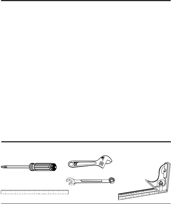
TOOLS NEEDED
The following tools (not included) are needed for making adjustments or installing the knives:
|
ADJUSTABLE WRENCH |
COMBINATION |
|
PHILLIPS SCREWDRIVER |
SQUARE |
||
|
|||
|
|
OPEN END WRENCH (1/2 IN.)
STRAIGHT EDGE
Fig. 7
12
 Loading...