


OPERATOR’S MANUAL
10 in. CAST IRON TABLE SAW
TS3660
Your new table saw has been engineered and manufactured to our high standards for dependability, ease of operation, and operator safety. When properly cared for, it will give you years of rugged, trouble-free performance.
 WARNING:
To reduce the risk of injury, the user must read and understand the operator’s manual before using this product.
Thank you for buying a RIDGID® product.
SAVE THIS MANUAL FOR FUTURE REFERENCE

TABLE OF CONTENTS |
|
Introduction ...................................................................................................................................................................... |
2 |
General Safety Rules..................................................................................................................................................... |
3-4 |
Specific Safety Rules..................................................................................................................................................... |
4-5 |
Symbols......................................................................................................................................................................... |
6-7 |
Electrical ...................................................................................................................................................................... |
8-10 |
Glossary of Terms........................................................................................................................................................... |
11 |
Features..................................................................................................................................................................... |
12-13 |
Tools Needed ................................................................................................................................................................. |
14 |
Loose Parts................................................................................................................................................................ |
15-16 |
Assembly ................................................................................................................................................................... |
17-28 |
Operation................................................................................................................................................................... |
29-40 |
Adjustments............................................................................................................................................................... |
41-47 |
Maintenance................................................................................................................................................................... |
48 |
Accessories .................................................................................................................................................................... |
48 |
Troubleshooting......................................................................................................................................................... |
49-50 |
Warranty ......................................................................................................................................................................... |
51 |
Parts Ordering/Service ................................................................................................................................................... |
52 |
INTRODUCTION |
|
This tool has many features for making the use of this product more pleasant and enjoyable. Safety, performance, and dependability have been given top priority in the design of this product making it easy to maintain and operate.
2

GENERAL SAFETY RULES
 WARNING:
Read and understand all instructions. Failure to follow all instructions listed below, may result in electric shock, fire and/or serious personal injury.
READ ALL INSTRUCTIONS
KNOW YOUR POWER TOOL. Read the operator’s manual carefully. Learn the saw’s applications and limitationsaswellasthespecificpotentialhazardsrelated to this tool.
GUARDAGAINSTELECTRICALSHOCKBYPREVENTING BODY CONTACT WITH GROUNDED SURFACES.
For example, pipes, radiators, ranges, refrigerator enclosures.
KEEP GUARDS IN PLACE and in good working order.
REMOVE ADJUSTING KEYS AND WRENCHES. Form habitofcheckingtoseethatkeysandadjustingwrenches are removed from tool before turning it on.
KEEPWORKAREACLEAN.Clutteredareasandbenches invite accidents. DO NOT leave tools or pieces of wood on the saw while it is in operation.
DO NOT USE IN DANGEROUS ENVIRONMENTS. Do not use power tools in damp or wet locations or expose to rain. Keep the work area well lit.
KEEP CHILDREN AND VISITORS AWAY. All visitors should wear safety glasses and be kept a safe distance from work area. Do not let visitors contact tool or extension cord while operating.
MAKE WORKSHOP CHILDPROOF with padlocks and master switches, or by removing starter keys.
DON’T FORCE TOOL. It will do the job better and safer at the feed rate for which it was designed.
USE RIGHT TOOL. Don’t force the tool or attachment to do a job it was not designed for. Don’t use it for a purpose not intended.
USETHEPROPEREXTENSIONCORD.Makesureyour extensioncordisingoodcondition.Useonlyacordheavy enough to carry the current your product will draw. An undersized cord will cause a drop in line voltage resulting in loss of power and overheating. A wire gauge size (A.W.G.) of at least 14 is recommended for an extension cord 25 feet or less in length. If in doubt, use the next heaviergauge.Thesmallerthegaugenumber,theheavier the cord.
DRESS PROPERLY. Do not wear loose clothing, gloves, neckties, or jewelry. They can get caught and draw you into moving parts. Rubber gloves and nonskid footwear are recommended when working outdoors. Also wear protective hair covering to contain long hair.
ALWAYS WEAR SAFETY GLASSES WITH SIDE SHIELDS. Everyday eyeglasses have only impactresistant lenses, they are NOT safety glasses.
SECUREWORK.Useclampsoravisetoholdworkwhen practical. It’s safer than using your hand and frees both hands to operate tool.
DON’T OVERREACH. Keep proper footing and balance at all times.
MAINTAIN TOOLS WITH CARE. Keep tools sharp andcleanforbetterandsaferperformance.Followinstructions for lubricating and changing accessories.
DISCONNECT TOOLS. When not in use, before servicing, or when changing attachments, blades, bits, cutters, etc., all tools should be disconnected.
AVOID ACCIDENTAL STARTING. Be sure switch is off when plugging in any tool.
USE RECOMMENDED ACCESSORIES. Consult the operator’s manual for recommended accessories. The use of improper accessories may risk injury.
NEVER STAND ON TOOL. Serious injury could occur if the tool is tipped or if the cutting tool is unintentionally contacted.
CHECK DAMAGED PARTS. Before further use of the tool, a guard or other part that is damaged should be carefullycheckedtodeterminethatitwilloperateproperly and perform its intended function. Check for alignment of moving parts, binding of moving parts, breakage of parts, mounting and any other conditions that may affect its operation. A guard or other part that is damaged must be properly repaired or replaced by an authorized service center to avoid risk of personal injury.
USE THE RIGHT DIRECTION OF FEED. Feed work into a blade or cutter against the direction of rotation of blade or cutter only.
NEVERLEAVETOOLRUNNINGUNATTENDED.TURN THE POWER OFF. Don’t leave tool until it comes to a complete stop.
PROTECT YOUR LUNGS. Wear a face or dust mask if the cutting operation is dusty.
PROTECT YOUR HEARING. Wear hearing protection during extended periods of operation.
DO NOT ABUSE CORD. Never yank cord to disconnect fromreceptacle.Keepcordawayfromheat,oil,andsharp edges.
USE OUTDOOR EXTENSION CORDS. When tool is used outdoors, use only extension cords with approved ground connection that are intended for use outdoors and so marked.
ALWAYS KEEP THE BLADE GUARD AND SPREADER (SPLITTER) IN PLACE and in working order.
KEEP BLADES CLEAN, SHARP, AND WITH SUFFICIENT SET. Sharp blades minimize stalling and kickback.
3

GENERAL SAFETY RULES
KEEP HANDS AWAY FROM CUTTING AREA. Keep hands away from blades. Do not reach underneath work or around or over the blade while blade is rotating. Do not attempt to remove cut material when blade is moving.
BLADE COASTS AFTER BEING TURNED OFF.
NEVER USE IN AN EXPLOSIVE ATMOSPHERE.
Normal sparking of the motor could ignite fumes.
INSPECT TOOL CORDS PERIODICALLY. If damaged, have repaired by a qualified service technician at anauthorizedservicefacility.Theconductorwithinsulation havinganoutersurfacethatisgreenwithorwithoutyellow stripes is the equipment-grounding conductor. If repair or replacement of the electric cord or plug is necessary, do not connect the equipment-grounding conductor to a live terminal. Repair or replace a damaged or worn cord immediately. Stay constantly aware of cord location and keep it well away from the rotating blade.
INSPECT EXTENSION CORDS PERIODICALLY and replace if damaged.
GROUND ALL TOOLS. If tool is equipped with threeprong plug, it should be plugged into a three-hole electrical receptacle.
CHECK WITH A QUALIFIED ELECTRICIAN or service personnel if the grounding instructions are not completely understood or if in doubt as to whether the tool is properly grounded.
USE ONLY CORRECT ELECTRICAL DEVICES: 3-wire extension cords that have 3-prong grounding plugs and 3-pole receptacles that accept the tool's plug.
DO NOT MODIFY the plug provided. If it will not fit the outlet, have the proper outlet installed by a qualified electrician.
KEEP TOOL DRY, CLEAN, AND FREE FROM OIL AND GREASE.Always use a clean cloth when cleaning. Never
use brake fluids, gasoline, petroleum-based products, or any solvents to clean tool.
STAY ALERT AND EXERCISE CONTROL. Watch what you are doing and use common sense. Do not operate tool when you are tired. Do not rush.
DO NOT USE TOOL IF SWITCH DOES NOT TURN IT ON AND OFF. Have defective switches replaced by an authorized service center.
USE ONLY CORRECT BLADES. Do not use blades with incorrect size holes. Never use blade washers or blade bolts that are defective or incorrect. The maximum blade capacity of your saw is 10 in. (254 mm).
BEFORE MAKING A CUT, BE SURE ALL ADJUSTMENTS ARE SECURE.
BE SURE BLADE PATH IS FREE OF NAILS. Inspect for and remove all nails from lumber before cutting.
NEVER TOUCH BLADE or other moving parts during use.
NEVER START A TOOL WHEN ANY ROTATING COMPONENT IS IN CONTACT WITH THE WORKPIECE.
DO NOT OPERATE A TOOL WHILE UNDER THE INFLUENCE OF DRUGS, ALCOHOL, OR ANY MEDICATION.
WHENSERVICINGuseonlyidenticalreplacementparts. Use of any other parts may create a hazard or cause product damage.
USE ONLY RECOMMENDED ACCESSORIES listed in this manual or addendums. Use of accessories that are not listed may cause the risk of personal injury. Instructions for safe use of accessories are included with the accessory.
DOUBLE CHECK ALL SETUPS. Make sure blade is tight and not making contact with saw or workpiece before connecting to power supply.
SPECIFIC SAFETY RULES
FIRMLY BOLT THE SAW TO A WORK BENCH OR LEG STAND at approximately hip height.
NEVER OPERATE THE SAW ON THE FLOOR.
GUARD AGAINST KICKBACK. Kickback occurs when the blade stalls rapidly and workpiece is driven back towards the operator. It can pull your hand into the blade resulting in serious personal injury. Stay out of blade path and turn switch off immediately if blade binds or stalls.
USE RIP FENCE. Always use a fence or straight edge guide when ripping.
SUPPORT LARGE PANELS. To minimize risk of blade pinching and kickback, always support large panels.
REMOVE ALL FENCES AND AUXILIARY TABLES before transporting saw. Failure to do so can result in an accident causing possible serious personal injury.
ALWAYS USE BLADE GUARD,SPREADER, AND ANTIKICKBACK PAWLS on all “through-sawing” operations.
Through-sawing operations are those in which the blade cuts completely through the workpiece as in ripping or cross cutting. Keep the blade guard down, the anti-kick- back pawls down, and the spreader in place over the blade.
ALWAYS SECURE WORK firmly against the rip fence or miter gauge. NEVER use the rip fence during the same operation as the miter gauge.
ALWAYS USE A PUSH STICK FOR RIPPING NARROW STOCK. A push stick is a device used to push a workpiece through the blade instead of using your hands. Size and shape can vary but the push stick must always be narrower than the workpiece to prevent the push stick from contacting the saw blade. When ripping narrow stock, always use a push stick, so your hand does not come close to the saw blade. Use a featherboard and push blocks for non-through cuts.
4

SPECIFIC SAFETY RULES
NEVER perform any operation “freehand” which means using only your hands to support or guide the workpiece. Always use either the rip fence or miter fence to position and guide the work.
NEVER stand or have any part of your body in line with the path of the saw blade.
NEVER reach behind, over, or within three inches of the blade or cutter with either hand for any reason.
ALWAYS REMOVE THE RIP FENCE from the saw when cross cutting.
DO NOT USE THE MITER GAUGE AND RIP FENCE during the same operation.
NEVER use rip fence as cutoff gauge when cross cutting.
NEVER attempt to free a stalled saw blade without first turning the saw OFF and disconnecting the saw from the power source.
PROVIDE ADEQUATE SUPPORT to the rear and sides of the saw table for wide or long work pieces. Use a sturdy “outrigger” support if a table extension more than 24 inches long is attached to the saw.
AVOID KICKBACKS (work thrown back toward you) by:
a)Keeping blade sharp.
b)Keeping rip fence parallel to the saw blade.
c)Keeping spreader, anti-kickback pawls, and blade guard in place and operating.
d)Not releasing the work before it is pushed all the way past the saw blade using a push stick.
e)Not ripping work that is twisted or warped or does not have a straight edge to guide along the fence.
IF THE POWER SUPPLY CORD IS DAMAGED, it must be replaced only by the manufacturer or by an authorized service center to avoid risk.
AVOID AWKWARD OPERATIONS AND HAND POSITIONS where a sudden slip could cause your hand to move into the cutting tool.
USE ONLY RECOMMENDED ACCESSORIES listed in this manual or addendums. Use of accessories that are not listed may cause the risk of personal injury. Instructions for safe use of accessories are included with the accessory.
MAKESURETHEWORKAREAHASAMPLELIGHTING to see the work and that no obstructions will interfere with safe operation BEFORE performing any work using the table saw.
ALWAYS TURN OFF SAW before disconnecting it, to avoid accidental starting when reconnecting to power supply.
THIS TOOL should have the following markings:
a)Wear eye protection.
b)Use saw blade guard and spreader/riving knife for every operation for which it can be used, including all through sawing.
c)Keep hands out of the line of saw blade.
d)Use a push stick when required.
e)Pay particular attention to instructions on reducing risk of kickback.
f)Do not perform any operation freehand.
g)Never reach around or over the saw blade.
SAVE THESE INSTRUCTIONS. Refer to them frequently and use to instruct other users. If you loan someone this tool, loan them these instructions also.
 WARNING:
Some dust created by power sanding, sawing, grinding, drilling, and other construction activities contains chemicals known to cause cancer, birth defects or other reproductive harm. Some examples of these chemicals are:
•lead from lead-based paints,
•crystalline silica from bricks and cement and other masonry products, and
•arsenic and chromium from chemically-treated lumber.
Your risk from these exposures varies, depending on how often you do this type of work. To reduce your exposure to these chemicals: work in a well ventilated area, and work with approved safety equipment, such as those dust masks that are specially designed to filter out microscopic particles.
5

SYMBOLS
Some of the following symbols may be used on this tool. Please study them and learn their meaning. Proper interpretation of these symbols will allow you to operate the tool better and safer.
SYMBOL |
NAME |
DESIGNATION/EXPLANATION |
V |
Volts |
Voltage |
A |
Amperes |
Current |
Hz |
Hertz |
Frequency (cycles per second) |
W |
Watt |
Power |
min |
Minutes |
Time |
|
Alternating Current |
Type of current |
|
Direct Current |
Type or a characteristic of current |
no |
No Load Speed |
Rotational speed, at no load |
|
Class II Construction |
Double-insulated construction |
.../min |
Per Minute |
Revolutions, strokes, surface speed, orbits etc., per minute |
|
Wet Conditions Alert |
Do not expose to rain or use in damp locations. |
|
Read The Operator’s Manual |
To reduce the risk of injury, user must read and understand |
|
operator’s manual before using this product. |
|
|
|
|
|
Eye Protection |
Always wear safety goggles, safety glasses with side shields, or |
|
a full face shield when operating this product. |
|
|
|
|
|
Safety Alert |
Precautions that involve your safety. |
|
No Hands Symbol |
Failure to keep your hands away from the blade will result in |
|
serious personal injury. |
|
|
|
|
|
Hot Surface |
To reduce the risk of injury or damage, avoid contact with any |
|
hot surface. |
|
|
|
6

SYMBOLS
The following signal words and meanings are intended to explain the levels of risk associated with this product.
SYMBOL |
SIGNAL |
MEANING |
|
DANGER: |
Indicates an imminently hazardous situation, which, if not avoided, will |
|
result in death or serious injury. |
|
|
|
|
|
|
|
|
WARNING: |
Indicates a potentially hazardous situation, which, if not avoided, could |
|
result in death or serious injury. |
|
|
|
|
|
|
|
|
CAUTION: |
Indicates a potentially hazardous situation, which, if not avoided, may |
|
result in minor or moderate injury. |
|
|
|
|
|
|
|
|
CAUTION: |
(Without Safety Alert Symbol) Indicates a situation that may result in |
|
property damage. |
|
|
|
SERVICE
Servicing requires extreme care and knowledge and should be performed only by a qualified service technician. For service we suggest you return the product to your nearest
AUTHORIZED SERVICE CENTER for repair. When servicing, use only identical replacement parts.
 WARNING:
To avoid serious personal injury, do not attempt to use this product until you read thoroughly and understand completely the operator’s manual. If you do not understand the warnings and instructions in the operator’s manual, do not use this product. Call RIDGID® customer service for assistance.
 WARNING:
The operation of any power tool can result in foreign objects being thrown into your eyes, which can result in severe eye damage. Before beginning power tool operation, always wear safety goggles or safety glasses with side shields and, when needed, a full face shield. We recommend Wide Vision Safety Mask for use over eyeglasses or standard safety glasses with side shields. Always use eye protection which is marked to comply with ANSI Z87.1.
SAVE THESE INSTRUCTIONS
7
ELECTRICAL
EXTENSION CORDS
Use only 3-wire extension cords that have 3-prong grounding plugs and 3-pole receptacles that accept the tool's plug. Whenusingapowertoolataconsiderabledistancefromthe power source, use an extension cord heavy enough to carry the current that the tool will draw. An undersized extension cord will cause a drop in line voltage, resulting in a loss of power and causing the motor to overheat. Use the chart providedbelowtodeterminetheminimumwiresizerequired in an extension cord. Only round jacketed cords listed by Underwriter's Laboratories (UL) should be used.
**Ampere rating (on tool faceplate)
|
0-2.0 |
2.1-3.4 |
3.5-5.0 |
5.1-7.0 7.1-12.0 |
12.1-16.0 |
|
|
|
|
|
|||
Cord Length |
Wire Size (A.W.G.) |
|
|
|||
|
|
|
|
|
|
|
25' |
16 |
16 |
16 |
16 |
14 |
14 |
|
|
|
|
|
|
|
50' |
16 |
16 |
16 |
14 |
14 |
12 |
|
|
|
|
|
|
|
100' |
16 |
16 |
14 |
12 |
10 |
— |
**Used on 12 gauge - 20 amp circuit.
NOTE: AWG = American Wire Gauge
When working with the tool outdoors, use an extension cord that is designed for outside use. This is indicated by the letters “WA” on the cord’s jacket.
Before using an extension cord, inspect it for loose or exposed wires and cut or worn insulation.
 WARNING:
Keep the extension cord clear of the working area. Position the cord so that it will not get caught on lumber, tools or other obstructions while you are working with a power tool. Failure to do so can result in serious personal injury.
 WARNING:
Check extension cords before each use. If damaged replace immediately. Never use product with a damaged cord since touching the damaged area could cause electrical shock resulting in serious injury.
ELECTRICAL CONNECTION
This product is powered by a precision built electric motor. It should be connected to a power supply that is 120 V, 60 Hz, AC only (normal household current). Do not operate this product on direct current (DC). A substantial voltage drop will cause a loss of power and the motor will overheat. If the saw does not operate when plugged into an outlet, double check the power supply.
SPEED AND WIRING
The no-load speed of this tool is approximately 3,450 rpm. This speed is not constant and decreases under a load or with lower voltage. For voltage, the wiring in a shop is as important as the motor’s horsepower rating. A line intended only for lights cannot properly carry a power tool motor. Wire that is heavy enough for a short distance will be too light for a greater distance. A line that can support one power tool may not be able to support two or three tools.
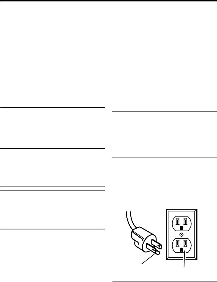
GROUNDING INSTRUCTIONS
Thisproductmustbegrounded.Intheeventofamalfunction orbreakdown,groundingprovidesapathofleastresistancefor electriccurrenttoreducetheriskofelectricshock.Thistoolis equippedwithanelectriccordhavinganequipment-grounding conductor and a grounding plug. The plug must be plugged intoamatchingoutletthatisproperlyinstalledandgrounded in accordance with all local codes and ordinances.
Do not modify the plug provided. If it will not fit the outlet, have the proper outlet installed by a qualified electrician.
 WARNING:
Improper installation of the grounding plug is able to result in a risk of electric shock. When repair or replacement of the cord is required, do not connect the grounding wire to either flat blade terminal. The wire with insulation having an outer surface that is green with or without yellow stripes is the grounding wire.
Check with a qualified electrician or service personnel if the grounding instructions are not completely understood, or if in doubt as to whether the tool is properly grounded.
Repair or replace a damaged or worn cord immediately.
This product is for use on a nominal 120 volt circuit and has a grounding plug similar to the plug illustrated in figure 1. Only connect the product to an outlet having the same configuration as the plug. Do not use an adapter with this product.
GROUNDING |
120 V GROUNDED OUTLET |
PIN |
|
|
Fig. 1 |
8
ELECTRICAL
 WARNING:
To prevent possible electrical hazards, have a qualified electrician check the line if you are not certain that it is properly wired.
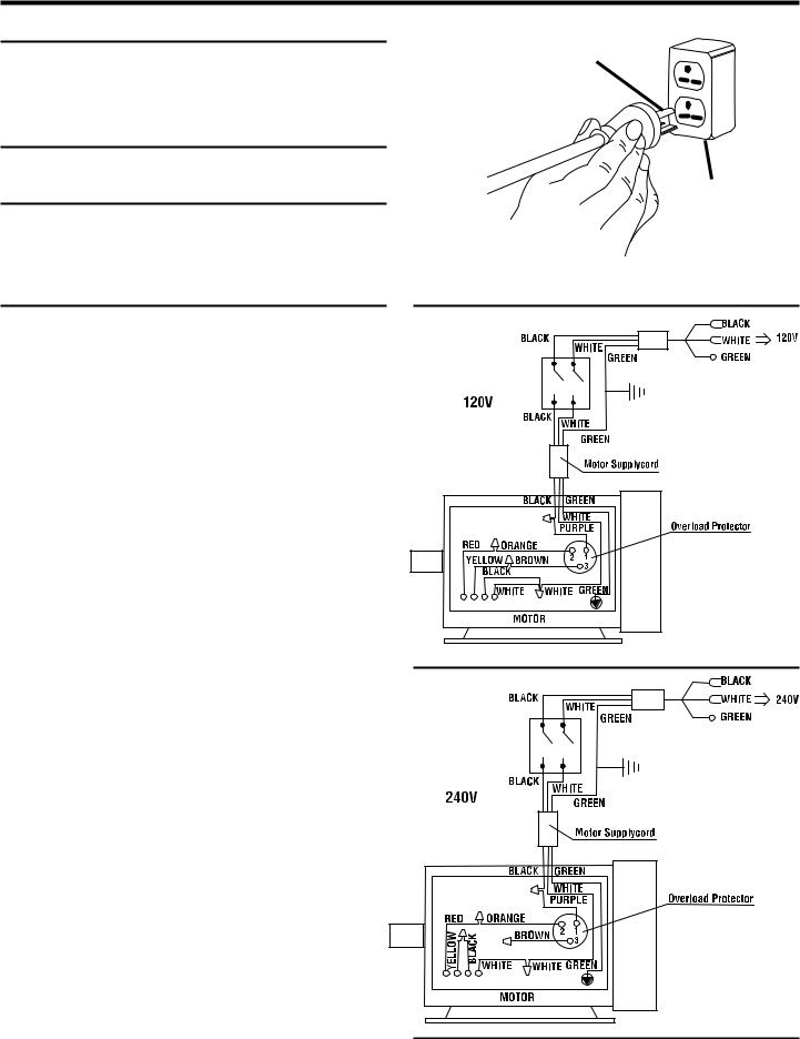
CHANGING MOTOR VOLTAGE
See Figures 2 - 4.
 WARNING:
Electric shock can kill. To reduce the risk of serious personal injury, never connect plug to power source until all assembly steps are completed.
NOTE: The table saw is prewired at the factory for 120 V, 60 Hz. Use the following procedures to change motor voltage from 120 V to 240 V.
Unplug the saw.
Located on the top of the motor is the junction box. Remove the phillips screw at the back of the junction box then lift off the cover.
Remove and discard the electrical tape from the wire connectors. Remove wire connectors.
Reconnect the leads.
Reinstall the wire connectors and wrap each wire with two layers of new UL listed electrical tape.
Recheck your wiring with the wiring diagrams.
Reinstall the junction box cover using the phillips screw.
Cut off the 120 volt power cord plug and replace it with a 3-prong 240 volt, 15 amp. UL listed plug.
Connect the power cord white and black leads, respectively, to the "hot" plug blade terminals. Connect the power cord green grounding wire to the plug ground prong terminal.
Plug your table saw into a 220-240 V, 15 amp., 3-prong receptacle. Make certain the receptacle is connected to a 240 V, AC power supply through a 240 V branch circuit having at least a 15 amp capacity and protected by a 15 amp time-delay fuse or circuit breaker.
GROUNDING
PIN
COVER OF
GROUNDED
OUTLET BOX
FOR USE WITH 220-240 VOLT |
Fig. 2 |
|
Fig. 3
Fig. 4
9
ELECTRICAL
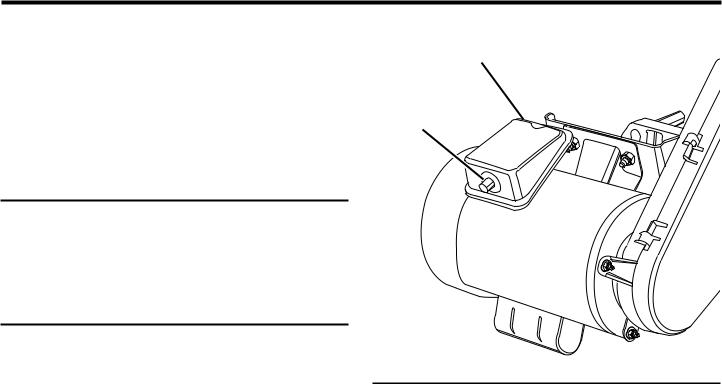
MOTOR THERMAL OVERLOAD PROTECTOR
See Figure 5.
Yourtablesawcomesequippedwithamanual-resetthermal- overload protector designed to open the power line circuit whenthemotortemperatureexceedsasafelevel,whenmotor is overloaded, or when a low voltage condition exists.
NOTE: This motor should be blown out or vacuumed frequently to prevent sawdust buildup which can interfere with normal motor ventilation.
 WARNING:
To reduce the risk of serious personal injury from thrown objects or blade contact from unexpected starting, immediately turn off the table saw if the protector stops the table saw motor. Remove the switch key and allow the motor time to cool.
Oncethemotoriscooledtoasafeoperatingtemperature, reset the thermal overload protector by pushing the red button on the front of the junction box. An audible click will indicate the thermal overload protector is reset. Once the button is reset, the table saw may be started and operated as normal.
NOTE:Iftheredbuttonwon'tclickintoplaceimmediately, the motor is still too hot and must be allowed to cool.
Frequent “blowing” of fuses or tripping of circuit breakers may result if:
Motorisoverloaded.Overloadingcanoccurifaworkpiece is fed too rapidly or if the table saw is misaligned.
Motor circuit is fused differently from recommendations. Always follow instructions for the proper fuse/breaker. Do not use a fuse/breaker of greater capacity without consulting a qualified electrician.
Lowvoltage.Althoughthemotorisdesignedforoperation on the voltage and frequency specified on the motor, normal loads will be handled safely on voltage no more than ten percent above or below that figure. Heavy loads, however,requirethatvoltageatmotorterminalsequalthe voltage specified on the motor.
NOTE:Alwayschecktheconnections,theloadandthesupply circuit whenever the motor fails to perform satisfactorily.
JUNCTION
BOX
MANUAL RESET
BUTTON
Fig. 5
10
GLOSSARY OF TERMS
Anti-Kickback Pawls (radial arm and table saws)
A device which, when properly installed and maintained, is designed to stop the workpiece from being kicked back toward the front of the saw during a ripping operation.
Arbor
The shaft on which a blade or cutting tool is mounted.
Bevel Cut
A cutting operation made with the blade at any angle other than 90° to the table surface.
Chamfer
A cut removing a wedge from a block so the end (or part of the end) is angled rather than at 90°.
Compound Cut
A cross cut made with both a miter and a bevel angle.
Cross Cut
A cutting or shaping operation made across the grain or the width of the workpiece.
Cutter Head (planers and jointers)
A rotating piece of adjustable blades. The cutter head removes material from the workpiece.
Dado Cut
A non-through cut which produces a square-sided notch or trough in the workpiece (requires a special blade).
Featherboard
A device used to help control the workpiece by guiding it securely against the table or fence during any ripping operation.
FPM or SPM
Feet per minute (or strokes per minute), used in reference to blade movement.
Freehand
Performing a cut without the workpiece being guided by a fence, miter gauge, or other aids.
Gum
A sticky, sap-based residue from wood products.
Heel
Alignment of the blade to the fence.
Kerf
The material removed by the blade in a through cut or the slot produced by the blade in a non-through or partial cut.
Kickback
A hazard that can occur when the blade binds or stalls, throwing the workpiece back toward operator.
Leading End
The end of the workpiece pushed into the tool first.
Miter Cut
A cutting operation made with the workpiece at any angle to the blade other than 90°.
Non-Through Cuts
Any cutting operation where the blade does not extend completely through the thickness of the workpiece.
Push Blocks and Push Sticks
Devices used to feed the workpiece through the saw blade during cutting operations. A push stick (not a push block) should be used for narrow ripping operations. These aids help keep the operator's hands well away from the blade.
Pilot Hole (drill presses)
A small hole drilled in a workpiece that serves as a guide for drilling large holes accurately.
Resaw
Acuttingoperationtoreducethethicknessofthework-piece to make thinner pieces.
Resin
A sticky, sap-based substance that has hardened.
Revolutions Per Minute (RPM)
The number of turns completed by a spinning object in one minute.
Ripping or Rip Cut
A cutting operation along the length of the workpiece.
Riving Knife (table saws)
Also known as a spreader or splitter. A metal piece, slightly thinner than the saw blade, which helps keep the kerf open and also helps to prevent kickback.
Saw Blade Path
The area over, under, behind, or in front of the blade. As it applies to the workpiece, that area which will be or has been cut by the blade.
Set
The distance that the tip of the saw blade tooth is bent (or set) outward from the face of the blade.
Snipe (planers)
Depression made at either end of a workpiece by cutter blades when the workpiece is not properly supported.
Throw-Back
The throwing back of a workpiece usually caused by the workpiece being dropped into the blade or being placed inadvertently in contact with the blade.
Through Sawing
Any cutting operation where the blade extends completely through the thickness of the workpiece.
Workpiece or Material
The item on which the operation is being done.
Worktable
Surface where the workpiece rests while performing a cutting, drilling, planing, or sanding operation.
11
FEATURES
PRODUCT SPECIFICATIONS
Blade Diameter........................................................... |
10 in. |
Blade Arbor .............................................................. |
5/8 in. |
Cutting Depth at 0°................................................ |
3-3/8 in. |
Cutting Depth at 45°.............................................. |
2-1/4 in. |
ANTI-KICKBACK
PAWLS
SEPARATOR |
BLADE GUARD |
SAW |
|
(SPLITTER) |
ASSEMBLY |
||
BLADE |
|||
|
|
MITER
GAUGE
RIP FENCE
STORAGE
HOOKS
LEG 
STAND
BLADE HEIGHT
LOCK KNOB
LEVELING 
FOOT
Rating.............................. |
120 V, AC Only, 60 Hz, 13 |
Amps |
|
240 V, AC Only, 60 Hz, 6.5 |
Amps |
No Load Speed ..................................... |
3,450 r/min. (RPM) |
|
BEVEL |
|
LOCK |
|
LEVER |
|
|
BEVEL |
|
ADJUSTING |
|
HANDWHEEL |
|
RIP FENCE |
|
FRONT |
|
RAIL |
SWITCH |
LOCKING |
ASSEMBLY |
LEVER |
BEVEL SCALE
MITER GAUGE
STORAGE HOOK
HEIGHT
ADJUSTING
HANDWHEEL
HERC-U-LIFT™
MOBILE BASE
Fig. 6
12

FEATURES
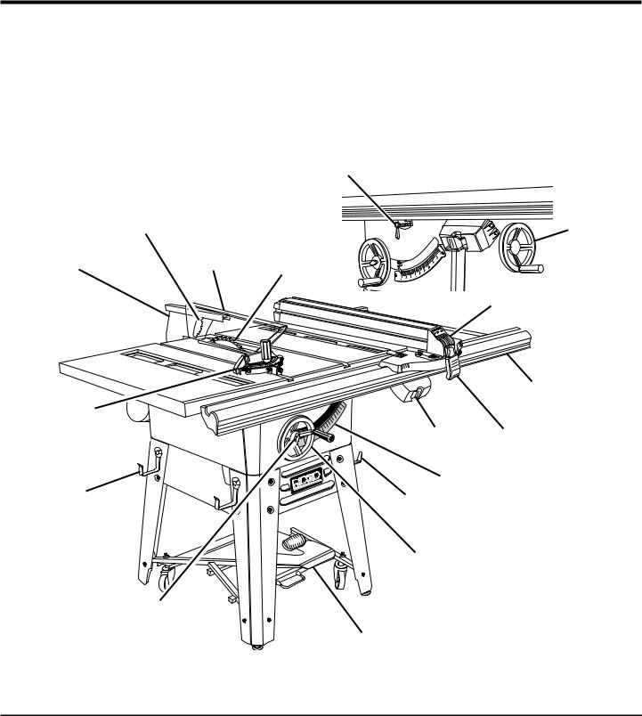
KNOW YOUR TABLE SAW
See Figure 6.
Before attempting to use this product, familiarize yourself with all operating features and safety rules.
OVERVIEW
The upper portion of the blade projects up through the table, surrounded by an insert called the throat plate. The height of the blade is set with a height adjusting handwheel on the front of the cabinet. Detailed instructions are provided in the Operation section of this manual for the basic cuts: rip cuts, cross cuts, miter cuts, bevel cuts, and compound cuts.
For cuts with the blade straight up and cutting across the grain (cross cuts or miter cuts), use the miter gauge to set the angle and push the wood into the blade. To cut with the blade straight up, along the grain of the wood (rip cuts), use the rip fence to guide the wood. Push smaller pieces with a push block or push stick.
To tilt the blade for a bevel cut, use the bevel adjusting handwheel on the side of the cabinet. A bevel scale on the frontofthecabinetshowsthebladeangle.Insidethecabinet, adjustable positive stops control the degree of tilt which can be adjusted with the screws in the top of the saw table. Use the miter gauge for a bevel cross cut (compound cut) and the rip fence for a bevel rip cut.
Your saw is designed to perform as a versatile, accurate, precision cutting tool that is easy to operate. It is equipped with the following features for convenience, ease of use, and high-quality performance:
ANTI-KICKBACKPAWLS-Kickbackisahazardinwhichthe workpiece is thrown back toward the operator. The toothed pawls are designed to snag the workpiece to prevent or reduce injury should kickback occur.
BEVEL ADJUSTING HANDWHEEL - Use this handwheel to set the angle of the blade for bevel cuts. It is located on the side of the cabinet.
BEVEL LOCK LEVER - This lever, placed just under the worktable surface on the front of the cabinet, locks the angle setting of the blade. Be sure the lever is unlocked before tilting the blade. If it is not unlocked, it may jam and bend the locking bolt.
BEVEL SCALE - The easy-to-read scale on the front of the workstand shows the exact blade angle.
BLADE - For maximum performance, it is recommended that you use the 40-tooth, 10 in. (254 mm) carbide tipped combination blade provided with your saw. Additional blade styles of the same high quality are available for specific operations such as ripping. Your local dealer can provide you with complete information.
 WARNING:
Do not use blades rated less than the speed of this tool. Failure to heed this warning could result in personal injury.
BLADE GUARD - Always keep the guard down over the blade for through-sawing cuts.
BLADEHEIGHTLOCKKNOB-Thisknob,inthecenterofthe height adjusting handwheel, locks the handwheel into place and must be unlocked before turning the handwheel.
HEIGHT ADJUSTING HANDWHEEL - Use this handwheel to lower and raise the blade for adjustments or replacement. It is located on the front of the cabinet.
HERC-U-LIFT MOBILE BASETM - This saw comes with a mobile base that allows for easy mobility.
IND-I-CUT™ ALIGNMENT DISC - A plastic insert on which marks may be made to indicate the location of the cut on the workpiece.
LOCKING LEVER - The lever on the front of the rip fence releases the rip fence or locks it in place.
MITER GAUGE - This miter gauge aligns the wood for a crosscut.Theeasy-to-readindicatorshowstheexactangle for a miter cut, with positive stops at 90° and 45°.
MITER GAUGE GROOVES - The miter gauge rides in these grooves on either side of the blade.
MOTOR-Thepowerfulinductionmotor,withcapacitorstart and poly V-belt drive, is housed in a sturdy steel base.
RAILS - Front and rear rails provide support for the rip fence and extension tables.
RIP FENCE - A sturdy metal fence guides the workpiece and is secured with the locking lever. Grooves run along the top and sides of the rip fence for use with clamps and jigs.
SCALE - Found on the front rail, the easy-to-read scale provides precise measurements in rip cuts.
SEPARATOR OR SPLITTER - A metal piece, slightly thinner than the saw blade which helps keep the kerf open and prevent kickback.
SWITCH ASSEMBLY - Your table saw has an easy access power switch located below the front rail. The yellow switch key must be removed from the blister pack and inserted into the switch before the saw can be operated. To lock the switch in the OFF position, remove the switch key from the switch. Place the key in a location that is inaccessible to children and others not qualified to use the tool.
13
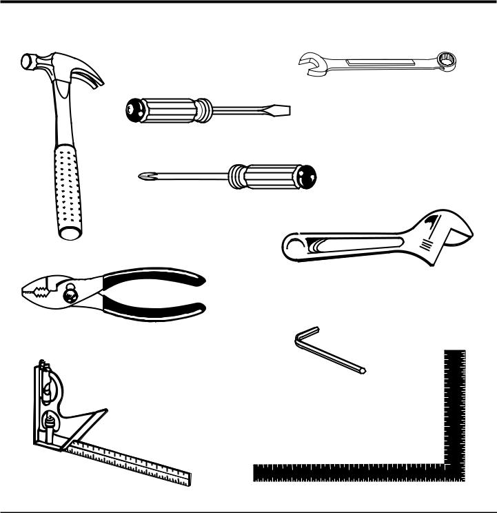
TOOLS NEEDED
The following tools (not included) are needed for assembly and alignment:
COMBINATION WRENCH (9) (10 mm, 11 mm, 12 mm, 13 mm, 14 mm, 17 mm, 1/2 in., 9/16 in. 11/16 in.)
SCREWDRIVER (2) (SMALL AND MEDIUM)
PHILLIPS SCREWDRIVER
HAMMER 

 ADJUSTABLE WRENCH
PLIERS
FRAMING SQUARE
Fig. 7
14
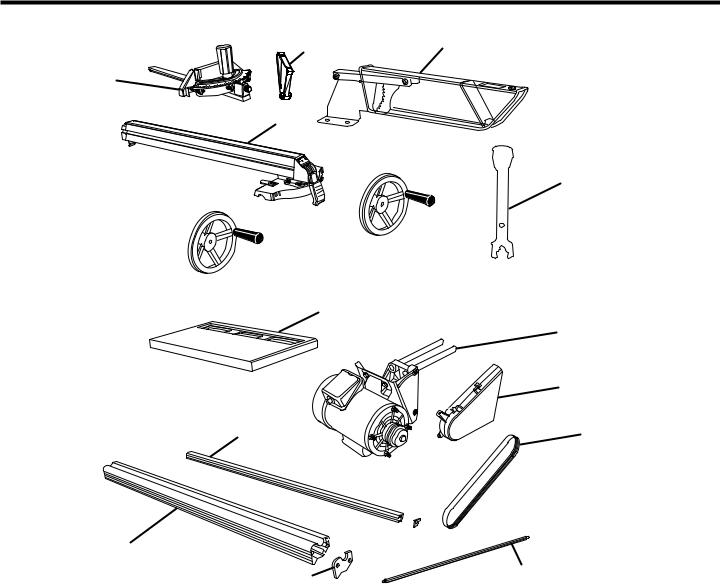
LOOSE PARTS
2 3
1
5
6 

 4
4
7 
11
12
13
10 |
14 |
8 
9
|
16 |
|
|
15 |
|
|
|
|
|
|
Fig. 8 |
|
|
|
|
|
|
Key |
|
|
Key |
|
|
No. |
Description |
Qty. |
No. |
Description |
Qty. |
1 |
Miter Gauge ....................................................... |
1 |
10 |
Back Rail ............................................................. |
1 |
2 |
Guard Support Assembly................................... |
1 |
11 |
Table Extension ................................................... |
2 |
3 |
Blade Guard Assembly....................................... |
1 |
12 |
Motor................................................................... |
1 |
4 |
Blade Wrench..................................................... |
2 |
13 |
Belt Guard ........................................................... |
1 |
5 |
Rip Fence ........................................................... |
1 |
14 |
Belt...................................................................... |
1 |
6 |
Bevel Adjusting Handwheel ............................... |
1 |
15 |
Spacer Bar .......................................................... |
1 |
7 |
Height Adjusting Handwheel.............................. |
1 |
16 |
Front End Cap (left and right).............................. |
2 |
8 |
Back End Cap (left and right) ............................. |
2 |
17 |
Blister Hardware Pack |
|
9 |
Front Rail |
1 |
|
(contents noted on blister pack) - not shown...... |
1 |
|
|
|
15
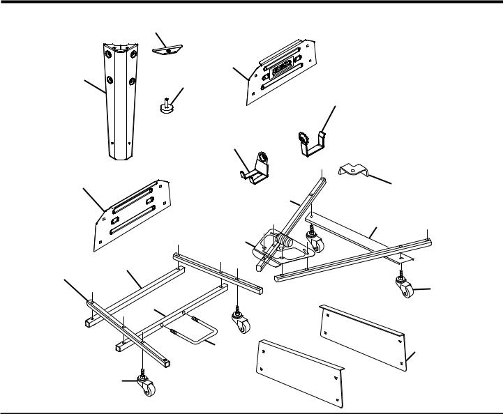
LOOSE PARTS LIST
|
6 |
|
|
|
|
2 |
|
|
1 |
5 |
|
|
|
|
|
|
|
11 |
|
|
|
12 |
|
|
3 |
|
10 |
|
|
|
|
|
|
7 |
|
|
|
|
13 |
|
|
14 |
|
|
17 |
|
|
|
8 |
|
|
|
|
|
9 |
|
16 |
|
|
|
|
15 |
4 |
|
9 |
|
|
|
|
|
Fig. 9 |
Key |
|
|
|
No. |
Description |
|
Qty. |
1 |
Leg ........................................................................................................................................................................ |
|
4 |
2 |
Front Brace ........................................................................................................................................................... |
|
1 |
3 |
Back Brace............................................................................................................................................................ |
|
1 |
4 |
Side Brace ............................................................................................................................................................ |
|
2 |
5 |
Leveling Feet......................................................................................................................................................... |
|
4 |
6 |
Foot Brace ............................................................................................................................................................ |
|
4 |
7 |
Rear Tube.............................................................................................................................................................. |
|
2 |
8 |
Front Tube............................................................................................................................................................. |
|
2 |
9 |
Swivel Caster ........................................................................................................................................................ |
|
4 |
10 |
Leg Bracket........................................................................................................................................................... |
|
4 |
11 |
Rip Fence Storage Hooks..................................................................................................................................... |
|
2 |
12 |
Miter Gauge Storage Hook................................................................................................................................... |
|
1 |
13 |
Center Brace......................................................................................................................................................... |
|
1 |
14 |
Unlock Pedal Assembly........................................................................................................................................ |
|
1 |
15 |
U-Bolt.................................................................................................................................................................... |
|
1 |
16 |
U-Bolt Tube........................................................................................................................................................... |
|
1 |
17 |
Tube Support ........................................................................................................................................................ |
|
1 |
18 |
Blister Hardware Pack, small (contents noted on blister pack) - not shown......................................................... |
1 |
|
19 |
Blister Hardware Pack, large (contents noted on blister pack) - not shown ......................................................... |
1 |
|
16
 Loading...