


OPERATOR’S MANUAL
14 in. BAND SAW
BS14002
ON I
PULL
OFF
O
10°
0°
15°
30°
4
Your new band saw has been engineered and manufactured to our high standards for dependability, ease of operation, and operator safety. When properly cared for, it will give you years of rugged, trouble-free performance.
WARNING:
To reduce the risk of injury, the user must read and understand the operator’s manual before using this product.
Thank you for buying a RIDGID product.
SAVE THIS MANUAL FOR FUTURE REFERENCE

TABLE OF CONTENTS |
|
n Introduction ...................................................................................................................................................................... |
2 |
n General Safety Rules........................................................................................................................................................ |
3 |
n Specific Safety Rules........................................................................................................................................................ |
4 |
n Symbols......................................................................................................................................................................... |
5-6 |
n Glossary of Terms............................................................................................................................................................. |
7 |
n Electrical ........................................................................................................................................................................ |
8-9 |
n Features..................................................................................................................................................................... |
10-11 |
n Tools Needed.................................................................................................................................................................. |
12 |
n Loose Parts................................................................................................................................................................ |
13-14 |
n Assembly ................................................................................................................................................................... |
15-24 |
n Operation................................................................................................................................................................... |
25-27 |
n Adjustments............................................................................................................................................................... |
28-29 |
n Maintenance.............................................................................................................................................................. |
30-31 |
n Accessories .................................................................................................................................................................... |
32 |
n Troubleshooting......................................................................................................................................................... |
32-33 |
n Warranty ......................................................................................................................................................................... |
35 |
n Parts Ordering/Service ................................................................................................................................................... |
36 |
INTRODUCTION |
|
This tool has many features for making its use more pleasant and enjoyable. Safety, performance, and dependability have been given top priority in the design of this product making it easy to maintain and operate.
2

GENERAL SAFETY RULES
WARNING:
Read and understand all instructions. Failure to follow all instructions listed below, may result in electric shock, fire and/or serious personal injury.
READ ALL INSTRUCTIONS
nKNOW YOUR POWER TOOL. Safe operation of this power tool requires that you read and understand this operator’s manual and all labels affixed to the tool. Learn its applications and limitations as well as the potential hazards.
nGUARD AGAINST ELECTRICAL SHOCK by preventing body contact with grounded surfaces such as pipes, radiators, ranges, refrigerator enclosures.
nKEEPGUARDSINPLACEandin goodworkingorder.Never operate the tool with any guard or cover removed. Make sure all guards are operating properly before each use.
nREMOVE ADJUSTING KEYS AND WRENCHES. Get in the habit - before turning on tool - that hex keys and adjusting wrenches are removed from tool.
nKEEP THE WORK AREA CLEAN. Cluttered work areas and work benches invite accidents.
nDO NOT USE IN DANGEROUS ENVIRONMENTS. Do not use power tools near gasoline or other flammable liquids, in damp or wet locations, or expose them to rain. Keep the work area well lighted.
nKEEP CHILDREN AND VISITORS AWAY. All visitors should wear safety glasses and be kept a safe distance fromworkarea.Donotletvisitorscontacttoolorextension cord while operating.
nMAKE WORKSHOP CHILDPROOF with padlocks and master switches or by removing starter keys.
nDO NOT FORCE THE TOOL it will do the job better and safer at the rate for which it was designed.
nUSE THE RIGHT TOOL FOR THE JOB. Do not force the tool or attachment to do a job for which it was not designed for. Use it only the way it was intended.
nUSE THE PROPER EXTENSION CORD. Make sure your extension cord is in good condition. Use only a cord heavy enough to carry the current your product will draw. An undersized cord will cause a drop in line voltage resulting in loss of power and overheating. A wire gage size (A.W.G.) of at least 16 is recommended for an extension cord 25 feet or less in length. If in doubt, use the next heavier gage. The smaller the gage number, the heavier the cord.
nWEAR PROPER APPAREL. Do not wear loose clothing, gloves, neckties, rings, bracelets, or other jewelry that could get caught and draw you into moving parts. Nonslip footwear is recommended. Wear protective covering over long hair.
nALWAYS WEAR SAFETY GLASSES WITH SIDE SHIELDS.Everydayeyeglasseshaveonlyimpactresistant lenses; they are NOT safety glasses.
nPROTECT YOUR LUNGS. Wear a face or dust mask if the operation is dusty.
nPROTECT YOUR HEARING. Wear hearing protection during extended periods of operation.
nSECURE WORK. Use clamps or a vise to hold the work when practical. It’s safer than using your hand and frees both hands to operate the tool.
nDONOTOVERREACH.Keepproperfootingandbalance at all times.
nMAINTAIN TOOLS WITH CARE. Keep tools sharp and cleanforbetterandsaferperformance.Followinstructions for lubricating and changing accessories.
nDISCONNECT ALL TOOLS. When not in use, before servicing,orwhenchangingattachments,alltoolsshould be disconnected.
nAVOID ACCIDENTAL STARTING. Be sure switch is off when plugging in any tool.
nUSE RECOMMENDED ACCESSORIES. Consult this operator’s manual for recommended accessories. The use of improper accessories may cause risk of injury.
nNEVERSTANDONTOOL.Seriousinjurycouldoccurifthe tool is tipped or if the bit is unintentionally contacted.
nCHECKDAMAGEDPARTS.Beforeusingthetool,aguard orotherpartthatisdamagedshouldbecarefullychecked to determine that it will operate properly and perform its intended function. Check for alignment of moving parts, bindingofmovingparts,breakageofparts,mountingand any other conditions that may affect operation. A guard or other part that is damaged must be properly repaired or replaced by an authorized service center to avoid risk of personal injury.
nNEVERLEAVETOOLRUNNINGUNATTENDED,TURN THE POWER OFF. Do not leave tool until it comes to a complete stop.
nDO NOT ABUSE CORD. Never carry the tool by cord or yank to disconnect from receptacle. Keep cord from heat, oil, and sharp edges.
nKEEP TOOL DRY, CLEAN, AND FREE FROM OIL AND GREASE. Always use a clean cloth when cleaning. Never use brake fluids, gasoline, petroleum-based products, or any solvents to clean tool.
nSTAY ALERT AND EXERCISE CONTROL. Watch what you are doing and use common sense. Do not operate tool when you are tired. Do not rush.
nINSPECT TOOL CORDS AND EXTENSION CORDS PERIODICALLY and, if damaged, have repaired by a qualified service technician. Stay constantly aware of cord location and keep it well away from the rotating wheel.
nNEVERUSEINANEXPLOSIVEATMOSPHERE. Normal sparking of the motor could ignite fumes.
nUSE ONLY OUTDOOR EXTENSION CORDS with approved ground connection that are intended for use outdoors and so marked.
nDO NOT USE TOOL IF SWITCH DOES NOT TURN IT ON AND OFF. Have defective switches replaced by an authorized service center.
nALWAYS TURN SWITCH OFF before disconnecting it to avoid accidental starting.
3

SPECIFIC SAFETY RULES
n AVOID AWKWARD OPERATIONS AND HAND POSITIONS where a sudden slip could cause your hand to move into the blade. ALWAYS make sure you have good balance.
nALLOW THE MOTOR TO COME UP TO FULL SPEED before starting a cut to avoid binding or stalling.
nREPLACEMENT PARTS. All repairs, whether electrical or mechanical, should be made by a qualified service technician at an authorized service center.
nWHEN SERVICINGuse only identical Ridgid replacement parts. Use of any other parts may create a hazard or cause product damage.
nDIRECTION OF FEED. Feed work into a blade or cutter against the direction or rotation of the blade or cutter only.
nBLADE COASTS AFTER TURN OFF.
nBE SURE THE BLADE PATH IS FREE OF NAILS. Inspect for and remove nails from lumber before cutting.
nKEEP HANDS AWAY FROM CUTTING AREA. Do not hand hold pieces so small that your fingers go under the blade guard. Do not reach underneath work or in blade cutting path with your hands and fingers for any reason.
nNEVER CUT MORE THAN ONE PIECE AT A TIME or stack more than one workpiece on the saw table at a time.
nFIRMLY CLAMP OR BOLT your saw to a stable, level workbench or table. The most comfortable table height is approximately waist height.
nDO NOT FEED THE MATERIAL TOO QUICKLY. Do not force the workpiece against the blade.
nUSE ONLY CORRECT BLADES. Use the right blade size, style and cutting speed for the material and the type of cut. Blade teeth should point down toward the table.
nBEFOREMAKINGACUT,BESUREALLADJUSTMENTS ARE SECURE.
nALWAYSSUPPORTLARGEWORKPIECESwhilecutting to minimize risk of blade pinching and kickback. Saw may slip, walk or slide while cutting large or heavy boards.
nDO NOT REMOVE JAMMED CUTOFF PIECES until blade has stopped.
nNEVER START THE TOOL when the blade is in contact with the workpiece.
nNEVER TOUCH BLADE or other moving parts during use.
nBEFORE CHANGING THE SETUP, REMOVING COVERS, GUARDS OR BLADES, unplug the saw and remove the switch key.
nHOLD THE WORKPIECE firmly against the saw table.
nTO AVOID ACCIDENTAL BLADE CONTACT, minimize blade breakage, and provide maximum blade support, always adjust the blade guide assembly to just clear the workpiece.
nKEEPBLADESCLEAN,SHARP,ANDWITHSUFFICIENT SET. Sharp blades minimize stalling and kickbacks.
nALWAYS TURN OFF SAW before disconnecting it to avoid accidental starting when reconnecting to a power source.
nDO NOT OPERATE THIS TOOL WHILE UNDER THE INFLUENCE OF DRUGS, ALCOHOL OR ANY MEDICATION.
nSTAY ALERT AND EXERCISE CONTROL. Watch what you are doing and use common sense. Do not operate tool when you are tired. Do not rush.
nMAKE SURE WORK AREA HAS AMPLE LIGHTING to see the work and that no obstructions will interfere with safe operation BEFORE performing any work using your saw.
nTHE BLADE GUIDES HAVE BEEN PRESET AT THE FACTORY. These settings are functional for some applications. We recommend that you check and adjust blade guide settings before first use of your saw. Refer to
“Adjusting thrust bearings, blade guide support, and blade guides” procedures explained in the adjustments section of this operator’s manual.
nSAVE THESE INSTRUCTIONS. Refer to them frequently and use them to instruct other users. If you loan someone this tool, loan them these instructions also.
WARNING:
Somedustcreatedbypowersanding,sawing,grinding,drilling,andotherconstructionactivitiescontainschemicals known to cause cancer, birth defects or other reproductive harm. Some examples of these chemicals are:
•lead from lead-based paints,
•crystalline silica from bricks and cement and other masonry products, and
•arsenic and chromium from chemically-treated lumber.
Your risk from these exposures varies, depending on how often you do this type of work. To reduce your exposure to these chemicals: work in a well ventilated area, and work with approved safety equipment, such as those dust masks that are specially designed to filter out microscopic particles.
4
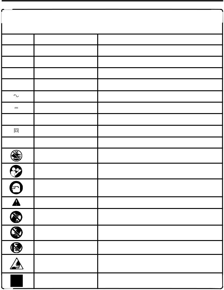
SYMBOLS
Some of the following symbols may be used on this tool. Please study them and learn their meaning. Proper interpretation of these symbols will allow you to operate the tool better and safer.
SYMBOL |
NAME |
DESIGNATION/EXPLANATION |
V |
Volts |
Voltage |
A |
Amperes |
Current |
Hz |
Hertz |
Frequency (cycles per second) |
W |
Watt |
Power |
min |
Minutes |
Time |
|
Alternating Current |
Type of current |
|
Direct Current |
Type or a characteristic of current |
no |
No Load Speed |
Rotational speed, at no load |
|
Class II Construction |
Double-insulated construction |
.../min |
Per Minute |
Revolutions, strokes, surface speed, orbits etc., per minute |
|
Wet Conditions Alert |
Do not expose to rain or use in damp locations. |
|
Read The Operator’s Manual |
To reduce the risk of injury, user must read and understand |
|
operator’s manual before using this product. |
|
|
|
|
|
Eye Protection |
Always wear safety goggles or safety glasses with side shields |
|
and a full face shield when operating this product. |
|
|
|
|
|
Safety Alert |
Precautions that involve your safety. |
|
No Hands Symbol |
Failure to keep your hands away from the blade will result in |
|
serious personal injury. |
|
|
|
|
|
No Hands Symbol |
Failure to keep your hands away from the blade will result in |
|
serious personal injury. |
|
|
|
|
|
No Hands Symbol |
Failure to keep your hands away from the blade will result in |
|
serious personal injury. |
|
|
|
|
|
No Hands Symbol |
Failure to keep your hands away from the blade will result in |
|
serious personal injury. |
|
|
|
|
|
Hot Surface |
To reduce the risk of injury or damage, avoid contact with |
|
any hot surface. |
|
|
|
5
SYMBOLS
The following signal words and meanings are intended to explain the levels of risk associated with this product.
SYMBOL |
SIGNAL |
MEANING |
|
|
DANGER: |
Indicates an imminently hazardous situation, which, if not avoided, will |
|
|
result in death or serious injury. |
||
|
|
||
|
|
|
|
|
WARNING: |
Indicates a potentially hazardous situation, which, if not avoided, could |
|
|
result in death or serious injury. |
||
|
|
||
|
|
|
|
|
CAUTION: |
Indicates a potentially hazardous situation, which, if not avoided, may |
|
|
result in minor or moderate injury. |
||
|
|
||
|
|
|
|
|
CAUTION: |
(Without Safety Alert Symbol) Indicates a situation that may result in |
|
|
property damage. |
||
|
|
||
SERVICE
Servicing requires extreme care and knowledge and should be performed only by a qualified service technician. For service we suggest you return the product to your nearest
AUTHORIZED SERVICE CENTER for repair. When servicing, use only identical replacement parts.
WARNING:
To avoid serious personal injury, do not attempt to use this product until you read thoroughly and understand completely the operator’s manual. Save this operator’s manual and review frequently for continuing safe operation and instructing others who may use this product.
WARNING:
The operation of any power tool can result in foreign objects being thrown into your eyes, which can result in severe eye damage. Before beginning power tool operation, always wear safety goggles or safety glasses with side shields and a full face shield when needed. We recommend Wide Vision Safety Mask for use over eyeglasses or standard safety glasses with side shields. Always use eye protection which is marked to comply with ANSI Z87.1.
SAVE THESE INSTRUCTIONS
6

GLOSSARY OF TERMS
Bevel Cut
A cutting operation made with the saw table at any angle other than 90° to the blade.
Compound Cut
A compound cut is a cut made using a miter angle and a bevel angle at the same time.
Crosscut
A cutting or shaping operation made across the grain or the width of the workpiece.
Freehand (for band saw)
Performing a cut without the workpiece properly supported on the saw table.
Gum
A sticky, sap-based residue from wood products.
Kerf
Thematerialremovedbythebladeinathroughcutortheslot produced by the blade in a non-through cut or partial cut.
Kickback
A hazard that can occur when the blade binds or stalls, throwing the workpiece back toward operator.
Leading End
The end of the workpiece pushed into the cutting tool first.
Miter Cut
A cutting operation made with the workpiece at any angle to the blade other than 90°.
Push Stick
A device used to feed the workpiece through the saw blade duringnarrowcuttingoperations.It helpskeeptheoperator's hands well away from the blade.
Resaw
A cutting operation to reduce the thickness of the workpiece to make thinner pieces.
Resin
A sticky, sap-based substance that has hardened.
Ripping
A cutting operation along the length of the workpiece.
Saw Blade Path
The area directly in line — over, under, behind or in front of the blade. As it applies to the workpiece, that area which will be or has been cut by the blade.
Set
The distance that the tip of the saw blade tooth is bent (or set) outward from the face of the blade.
FPM
2,700 surface feet per minute, used in reference to surface speed of blade.
Throw-Back
Saw throwing back a workpiece in a manner similar to a kickback.Usuallyassociatedwithacauseotherthanthekerf closing, such as a workpiece being dropped into the blade or being placed inadvertently in contact with the blade.
Through Sawing
Any cutting operation where the blade extends completely through the thickness of the workpiece.
Workpiece
The item on which the cutting operation is being done. The surfaces of a workpiece are commonly referred to as faces, ends, and edges.
Worktable
The surface on which the workpiece rests while performing a cutting or sanding operation.
7
ELECTRICAL
EXTENSION CORDS
Use only 3-wire extension cords that have 3-prong grounding plugs and 3-pole receptacles that accept the tool's plug. When using a power tool at a considerable distance from the power source, use an extension cord heavy enough to carry the current that the tool will draw. An undersized extension cord will cause a drop in line voltage, resulting in a loss of power and causing the motor to overheat. Use the chart provided below to determine the minimum wire size required in an extension cord. Only round jacketed cords listed by Underwriter's Laboratories (UL) should be used.
**Ampere rating (on tool faceplate)
|
0-2.0 |
2.1-3.4 |
3.5-5.0 |
5.1-7.0 7.1-12.0 |
12.1-16.0 |
|
Cord Length |
Wire Size (A.W.G.) |
|
|
|||
|
|
|
|
|
|
|
25' |
16 |
16 |
16 |
16 |
14 |
14 |
|
|
|
|
|
|
|
50' |
16 |
16 |
16 |
14 |
14 |
12 |
|
|
|
|
|
|
|
100' |
16 |
16 |
14 |
12 |
10 |
— |
**Used on 12 gauge - 20 amp circuit.
NOTE: AWG = American Wire Gauge
When working with the tool outdoors, use an extension cord that is designed for outside use. This is indicated by the letters "WA" on the cord's jacket.
Before using an extension cord, inspect it for loose or exposed wires and cut or worn insulation.
WARNING:
Keep the extension cord clear of the working area. Position the cord so that it will not get caught on lumber, tools or other obstructions while you are working with a power tool. Failure to do so can result in serious personal injury.
SPEED AND WIRING
The no-load speed of this tool is approximately 3000 fpm. This speed is not constant and decreases under a load or with lower voltage. For voltage, the wiring in a shop is as important as the motor’s horsepower rating. A line intended only for lights cannot properly carry a power tool motor. Wire that is heavy enough for a short distance will be too light for a greater distance. A line that can support one power tool may not be able to support two or three tools.
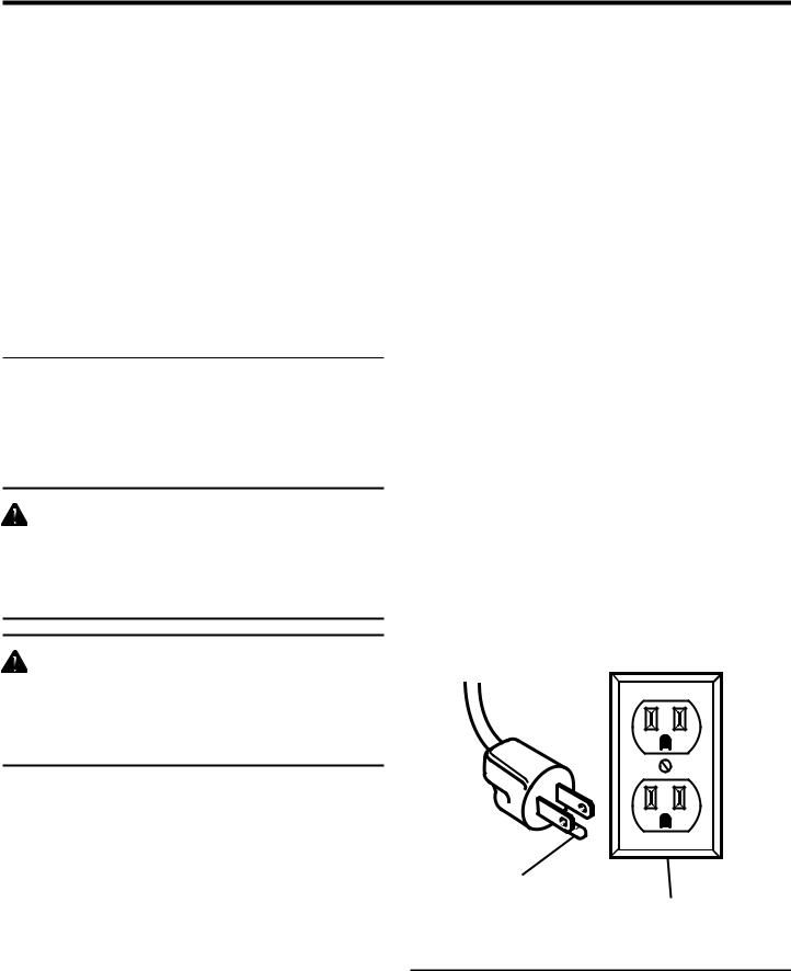
GROUNDING INSTRUCTIONS
In the event of a malfunction or breakdown, grounding provides a path of least resistance for electric current to reduce the risk of electric shock. This tool is equipped with an electric cord having an equipment-grounding conductor and a grounding plug. The plug must be plugged into a matching outlet that is properly installed and grounded in accordance with all local codes and ordinances.
Do not modify the plug provided. If it will not fit the outlet, have the proper outlet installed by a qualified electrician. Improper connection of the equipment-grounding conductor can result in a risk of electric shock. The conductor with insulation having an outer surface that is green with or without yellow stripes is the equipment-grounding conductor. If repair or replacement of the electric cord or plug is necessary, do not connect the equipment-grounding conductor to a live terminal.
Check with a qualified electrician or service personnel if the grounding instructions are not completely understood, or if in doubt as to whether the tool is properly grounded.
Repair or replace a damaged or worn cord immediately. This tool is intended for use on a circuit that has an outlet like the one shown in figure 1. It also has a grounding pin like the one shown.
WARNING:
Check extension cords before each use. If damaged replace immediately. Never use tool with a damaged cord since touching the damaged area could cause electrical shock resulting in serious injury.
ELECTRICAL CONNECTION
This tool is powered by a precision built electric motor. It should be connected to a power supply that is 120 volts, 60 Hz, AC only (normal household current). Do not operate this tool on direct current (DC). A substantial voltage drop will cause a loss of power and the motor will overheat. If the saw does not operate when plugged into an outlet, double check the power supply.
GROUNDING
PIN COVER OF GROUNDED OUTLET BOX
Fig. 1
8
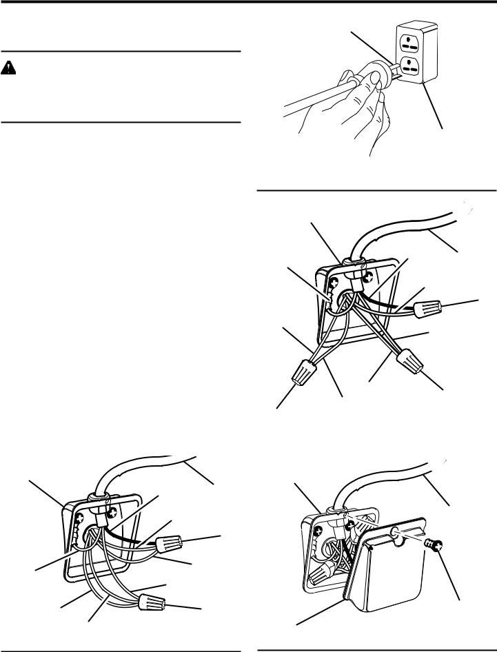
ELECTRICAL
CHANGING MOTOR VOLTAGE
See Figures 2 - 5.
WARNING:
Electric shock can kill. To reduce the risk of serious personal injury, never connect plug to power source until all assembly steps are completed.
NOTE: The band saw is prewired at the factory for 120 volts, 60Hz.Usethefollowingprocedurestochangemotorvoltage from 120 volts to 240 volts.
nUnplug the saw.
nLocated on the side of the motor is the junction box. Remove the Phillips screw at the back of the junction box then lift off the cover.
nRemove and discard the electrical tape from the wire connectors. Remove wire connectors.
nReconnect the leads.
nReinstall the wire connectors and wrap each wire with two layers of new UL listed electrical tape.
nRecheck your wiring with the wiring diagrams.
nReinstall the junction box cover using the Phillips screw.
nCut off the 120 volt power cord plug and replace it with a 3-prong 240 volt, 15 amp. UL listed plug.
nConnect the power cord white and black leads, respectively, to the "hot" plug blade terminals. Connect the power cord green grounding wire to the plug ground prong terminal.
nPlug your table saw into a 220-240 volt, 15 amp., 3-prong receptacle. Make certain the receptacle is connected to a 240 volt, AC power supply through a 240 volt branch circuit having at least a 15 amp capacity and protected by a 15 amp time-delay fuse or circuit breaker.
MOTOR |
|
|
JUNCTION BOX |
POWER CORD |
|
|
|
|
|
BLACK |
POWER CORD |
|
|
BLACK |
|
WHITE NO. 1 |
|
|
|
WIRE |
|
|
NUT |
|
|
WHITE NO. 3 |
POWER CORD |
POWER CORD |
|
GREEN GROUND |
WHITE |
|
WHITE NO. 4 |
WIRE NUT |
|
|
||
|
WHITE NO. 2 |
|
|
FOR USE WITH 110-120 VOLT |
Fig. 2 |
GROUNDING PIN
|
COVER OF GROUNDED |
||
|
OUTLET BOX |
||
FOR USE WITH 220-240 VOLT |
Fig. 3 |
||
MOTOR |
|
|
|
JUNCTION BOX |
|
|
|
POWER CORD |
POWER CORD |
||
BLACK |
POWER CORD |
||
GREEN GROUND |
|||
|
|
BLACK |
|
|
WHITE NO. 1 |
||
|
|
WIRE |
|
|
|
NUT |
|
WHITE NO. 2 |
POWER CORD |
||
|
|||
|
|
WHITE |
|
WHITE NO. 4 |
WIRE NUT |
|
WHITE NO. 3 |
||
|
||
WIRE NUT |
|
FOR USE WITH 220-240 VOLT |
Fig. 4 |
|
|
MOTOR |
|
JUNCTION BOX |
|
POWER CORD
|
MOTOR JUNCTION |
|
BOX SCREW |
MOTOR JUNCTION |
Fig. 5 |
BOX COVER |
9
FEATURES
SPECIFICATIONS
n Blade Width ................................................................................................................... |
1/8 in. to 3/4 in. (3 mm to 19 mm) |
n Blade Length ..................................................................................................................................... |
93-1/2 in. (237.5 cm) |
n Table Size...................................................................................................................... |
14 in. x 14 in. (355 mm x 355 mm) |
n Input............................................................................................................................................. |
120 Volt, 60Hz, 10 amps |
n No Load Speed................................................................................................................................................... |
2700 FPM |
n Dust Port............................................................................................................................................. |
2-1/4 in. (57.15 mm) |
n Net Weight.................................................................................................................................................. |
187 lbs. (85 kg) |
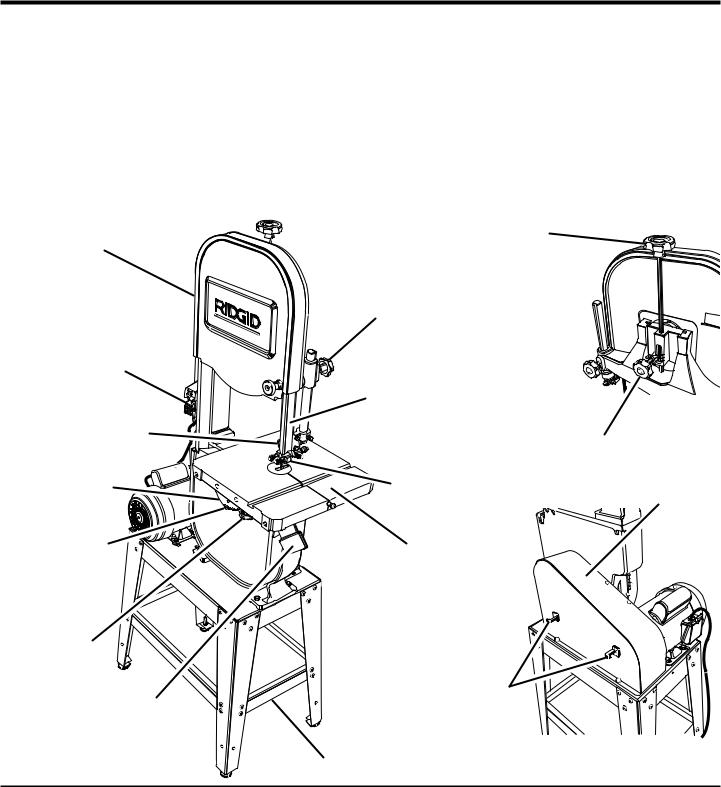
UPPER |
BLADE |
|
COVER |
||
TENSION KNOB |
||
|
BLADE GUARD
ADJUSTMENT KNOB
SWITCH AND
SWITCH KEY
|
|
PULL |
ON |
|
BLADE GUARD |
I |
OFF |
|
|
O |
|
ADJUST OFTENSION TOBLADE SCALE
13
42
1 |
3 |
4 |
8 |
8 |
1 |
|
8 |
THRUST |
TRACKING KNOB |
|
BEARINGS |
||
|
BEVEL SCALE |
BLADE GUIDES |
MOTOR |
|
PULLEY COVER |
|||
|
|
||
|
10° |
|
|
|
0° |
|
|
|
15° 30° 4 |
|
|
SCALE |
SAW TABLE |
|
|
INDICATOR |
|
|
LOCK KNOBS
DUST |
BLADE |
|
HANGERS |
||
EXHAUST PORT |
||
|
||
|
LEG STAND |
|
|
Fig. 6 |
10
FEATURES
KNOW YOUR BAND SAW
See Figure 6.
Before attempting to use this product, familiarize yourself with all operating Features and Safety Rules.
BLADE TENSION KNOB
Rotation of this knob will increase or decrease the tension on the blade.
TRACKING KNOB
Adjusts tracking to keep blade centered on the wheels.
BLADE GUIDES
Blade guides provide full support of the adjustable blade.
THRUST BEARINGS
Thrust bearings support the back of the blade and are adjustable for the various blade widths.
BLADE GUARD ADJUSTMENT KNOBS
Use the blade guide adjustment knobs to adjust the blade guide assembly. This keeps the blade from twisting or breaking.
SAW TABLE WITH 90° STOPS
Saw table tilts for angular cuts. Ensures saw table is perpendicular to blade. Use the bevel scale under saw table to measure angular settings.
TABLE LOCK KNOBS
Loosening the table lock knobs allows the saw table to be tilted at different angles. Tightening the table lock knobs locks the saw table in place.
HOUSING COVERS
Pull knob to expose wheels during blade changes or to clean out sawdust build-up.
DUST EXHAUST PORT
A 2-1/4 in. (57.15 mm) dust exhaust port makes dustless cutting possible by blowing the dust away from the user. Attach to the dust exhaust port when using a dust collection system or wet/dry vac.
BLADE GUARD
Protects the operator from coming in contact with the blade.
BLADE HANGERS
Extra blades may be stored here.
11
 Loading...