


OPERATOR'S MANUAL
15 in. DRILL PRESS
DP15501
Your new drill press has been engineered and manufactured to our high standards for dependability, ease of operation, and operator safety. When properly cared for, it will give you years of rugged, trouble-free performance.
WARNING:
To reduce the risk of injury, the user must read and understand the operator’s manual before using this product.
Thank you for buying a RIDGID product.
SAVE THIS MANUAL FOR FUTURE REFERENCE

TABLE OF CONTENTS |
|
n Introduction ...................................................................................................................................................................... |
2 |
n General Safety Rules........................................................................................................................................................ |
3 |
n Specific Safety Rules........................................................................................................................................................ |
4 |
n Symbols......................................................................................................................................................................... |
5-6 |
n Electrical ........................................................................................................................................................................... |
7 |
n Glossary of Terms............................................................................................................................................................. |
8 |
n Features....................................................................................................................................................................... |
9-10 |
n Unpacking ..................................................................................................................................................................... |
11 |
n Loose Parts..................................................................................................................................................................... |
12 |
n Tools Needed.................................................................................................................................................................. |
13 |
n Assembly ................................................................................................................................................................... |
13-17 |
n Operation................................................................................................................................................................... |
18-21 |
n Adjustments............................................................................................................................................................... |
22-26 |
n Maintenance................................................................................................................................................................... |
27 |
n Accessories .................................................................................................................................................................... |
28 |
n Troubleshooting.............................................................................................................................................................. |
29 |
n Warranty ......................................................................................................................................................................... |
31 |
n Parts Ordering/Service ................................................................................................................................................... |
32 |
INTRODUCTION |
|
Your drill press has many features for making the use of this product more pleasant and enjoyable. Safety, performance, and dependability have been given top priority in the design of this product making it easy to maintain and operate.
2

GENERAL SAFETY RULES
WARNING:
Read and understand all instructions. Failure to follow all instructions listed below, may result in electric shock, fire and/or serious personal injury.
READ ALL INSTRUCTIONS
nKNOW YOUR POWER TOOL. Safe operation of this power tool requires that you read and understand this operator’s manual and all labels affixed to the tool. Learn its applications and limitations as well as the potential hazards.
nGUARD AGAINST ELECTRICAL SHOCK by preventing body contact with grounded surfaces such as pipes, radiators, ranges, refrigerator enclosures.
nKEEP GUARDS IN PLACE and in good working order. Never operate the tool with any guard or cover removed. Make sure all guards are operating properly before each use.
nREMOVE ADJUSTING KEYS AND WRENCHES. Get in the habit - before turning on tool - that hex keys and adjusting wrenches are removed from tool.
nKEEP THE WORK AREA CLEAN. Cluttered work areas andworkbenchesinviteaccidents.DONOTleavetoolsor pieces of wood on the machine while it is in operation.
nDO NOT USE IN DANGEROUS ENVIRONMENTS. Do not use power tools near gasoline or other flammable liquids, in damp or wet locations, or expose them to rain. Keep the work area well lighted.
nKEEP CHILDREN AND VISITORS AWAY. All visitors should wear safety glasses and be kept a safe distance fromworkarea.Donotletvisitorscontacttoolorextension cord while operating.
nMAKE WORKSHOP CHILDPROOF with padlocks and master switches or by removing starter keys.
nDO NOT FORCE THE TOOL it will do the job better and safer at the rate for which it was designed.
nUSE THE RIGHT TOOL FOR THE JOB. Do not force the tool or attachment to do a job for which it was not designed for. Use it only the way it was intended.
nUSE THE PROPER EXTENSION CORD. Make sure your extension cord is in good condition. Use only a cord heavy enough to carry the current your product will draw. An undersized cord will cause a drop in line voltage resulting in loss of power and overheating. A wire gage size (A.W.G.) of at least 14 is recommended for an extension cord 25 feet or less in length. If in doubt, use the next heavier gage. The smaller the gage number, the heavier the cord.
nDRESS PROPERLY. Do not wear loose clothing, gloves, neckties, rings, bracelets, or other jewelry that could get caught and draw you into moving parts. Non-slip footwear is recommended. Wear protective covering over long hair.
n ALWAYS WEAR SAFETY GLASSES WITH SIDE SHIELDS. Everyday eyeglasses have only impact resistant lenses; they are not safety glasses.
nPROTECT YOUR LUNGS. Wear a face or dust mask if the operation is dusty.
nPROTECT YOUR HEARING. Wear hearing protection during extended periods of operation.
nSECURE WORK. Use clamps or a vise to hold the work when practical. It’s safer than using your hand and frees both hands to operate the tool.
nDONOTOVERREACH.Keepproperfootingandbalance at all times.
nMAINTAIN TOOLS WITH CARE. Keep tools sharp and cleanforbetterandsaferperformance.Followinstructions for lubricating and changing accessories.
nDISCONNECT ALL TOOLS. When not in use, before servicing,orwhenchangingattachments,alltoolsshould be disconnected.
nAVOID ACCIDENTAL STARTING. Be sure switch is off when plugging in any tool.
nUSE RECOMMENDED ACCESSORIES. Consult this operator’s manual for recommended accessories. The use of improper accessories may cause risk of injury.
nNEVERSTANDONTOOL.Seriousinjurycouldoccurifthe tool is tipped or if the bit is unintentionally contacted.
nCHECKDAMAGEDPARTS.Beforeusingthetool,aguard orotherpartthatisdamagedshouldbecarefullychecked to determine that it will operate properly and perform its intended function. Check for alignment of moving parts, bindingofmovingparts,breakageofparts,mountingand any other conditions that may affect operation. A guard or other part that is damaged must be properly repaired or replaced by an authorized service center to avoid risk of personal injury.
nNEVERLEAVETOOLRUNNINGUNATTENDED,TURN THE POWER OFF. Do not leave tool until it comes to a complete stop.
nDONOTABUSECORD.Neveryankthecordtodisconnect it from the receptacle. Keep the cord from heat, oil, and sharp edges.
nKEEP TOOL DRY, CLEAN, AND FREE FROM OIL AND GREASE.Always use a clean cloth when cleaning. Never usebrakefluids,gasoline,petroleum-basedproducts, or any solvents to clean tool.
nSTAY ALERT AND EXERCISE CONTROL. Watch what you are doing and use common sense. Do not operate tool when you are tired. Do not rush.
nDO NOT USE TOOL IF SWITCH DOES NOT TURN IT ON AND OFF. Have defective switches replaced by an authorized service center.
nALWAYS TURN SWITCH OFF before disconnecting it to avoid accidental starting.
3

SPECIFIC SAFETY RULES
nKEEP BITS CLEAN AND SHARP. Sharp bits minimize stalling. Dirty and dull bits may cause misalignment of the material and possible operator injury.
nKEEP HANDS AWAY FROM WORK AREA. Keep hands away from the bit. Restrain any loose clothing, jewelry, long hair, etc. that may become entangled in the bit.
nDO NOT wear gloves, necktie, or loose clothing.
nALWAYSCLAMPWORKPIECEANDBRACEAGAINST COLUMN TO PREVENT ROTATION. Never use your hand to hold the object while drilling.
nUSE RECOMMENDED SPEED FOR DRILL ACCESSORY AND WORKPIECE MATERIAL.
nBESUREDRILLBITORCUTTINGTOOLISSECURELY LOCKED IN THE CHUCK.
nBE SURE CHUCK KEY IS REMOVED from the chuck before connecting to power source or turning power
ON.
nADJUST THE TABLE OR DEPTH STOP TO AVOID DRILLINGINTOTHETABLE.Shutoffthepower,remove the drill bit, and clean the table before leaving machine.
nDO NOT CONNECT TOOL TO POWER SOURCE OR OPERATEUNTILITISCOMPLETELYASSEMBLEDAND INSTALLED ACCORDING TO THE INSTRUCTIONS. If any part of your drill press malfunctions or has been damaged or broken, do not operate until the part is properly repaired or replaced.
nNEVERPLACEYOURFINGERSINAPOSITIONWHERE THEY COULD CONTACT THE DRILL or other cutting tool if the workpiece should unexpectedly shift.
nNEVER PERFORM ANY OPERATION by moving the head or table with respect to one another. Do not turn the motor switch ON or start any operation before checking that the head and table support lock handle is clamped tight to column and head and table support collars are correctly positioned.
nBEFOREENGAGINGTHEPOWERSWITCHON,MAKE SURE THE BELT GUARD IS DOWN AND THE CHUCK IS INSTALLED PROPERLY.
nLOCKTHEMOTORSWITCHOFFWHENLEAVINGTHE DRILL PRESS. Do not perform layout, assembly, or setup work on the table while the cutting tool is rotating, switched on or connected to a power source.
nSAVETHESEINSTRUCTIONS.Refer to them frequently and use to instruct other users. If you loan someone this tool, loan them these instructions also.
 WARNING:
Somedustcreatedbypowersanding,sawing,grinding,drilling,andotherconstructionactivitiescontainschemicals known to cause cancer, birth defects or other reproductive harm. Some examples of these chemicals are:
•lead from lead-based paints,
•crystalline silica from bricks and cement and other masonry products, and
•arsenic and chromium from chemically-treated lumber.
Your risk from these exposures varies, depending on how often you do this type of work. To reduce your exposure to these chemicals: work in a well ventilated area, and work with approved safety equipment, such as those dust masks that are specially designed to filter out microscopic particles.
4
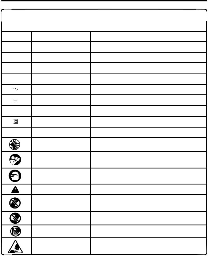
SYMBOLS
Some of the following symbols may be used on this tool. Please study them and learn their meaning. Proper interpretation of these symbols will allow you to operate the tool better and safer.
SYMBOL |
NAME |
DESIGNATION/EXPLANATION |
V |
Volts |
Voltage |
A |
Amperes |
Current |
Hz |
Hertz |
Frequency (cycles per second) |
W |
Watt |
Power |
min |
Minutes |
Time |
|
Alternating Current |
Type of current |
|
Direct Current |
Type or a characteristic of current |
no |
No Load Speed |
Rotational speed, at no load |
|
Class II Construction |
Double-insulated construction |
.../min |
Per Minute |
Revolutions, strokes, surface speed, orbits etc., per minute |
|
Wet Conditions Alert |
Do not expose to rain or use in damp locations. |
|
Read The Operator’s Manual |
To reduce the risk of injury, user must read and understand |
|
operator’s manual before using this product. |
|
|
|
|
|
Eye Protection |
Always wear safety goggles or safety glasses with side shields |
|
and a full face shield when operating this product. |
|
|
|
|
|
Safety Alert |
Precautions that involve your safety. |
|
No Hands Symbol |
Failure to keep your hands away from the blade will result in |
|
serious personal injury. |
|
|
|
|
|
No Hands Symbol |
Failure to keep your hands away from the blade will result in |
|
serious personal injury. |
|
|
|
|
|
No Hands Symbol |
Failure to keep your hands away from the blade will result in |
|
serious personal injury. |
|
|
|
|
|
No Hands Symbol |
Failure to keep your hands away from the blade will result in |
|
|
serious personal injury. |
5
SYMBOLS
The following signal words and meanings are intended to explain the levels of risk associated with this product.
SYMBOL SIGNAL |
MEANING |
DANGER: Indicates an imminently hazardous situation, which, if not avoided, will result in death or serious injury.
WARNING: Indicates a potentially hazardous situation, which, if not avoided, could result in death or serious injury.
CAUTION: Indicates a potentially hazardous situation, which, if not avoided, may result in minor or moderate injury.
CAUTION: (Without Safety Alert Symbol) Indicates a situation that may result in property damage.
SERVICE
Servicingrequiresextremecareandknowledgeandshouldbe performed only by a qualified service technician. For service we suggest you return the product to your nearest AUTHORIZED SERVICE CENTER for repair. When servicing, use only identical replacement parts.
WARNING:
To avoid serious personal injury, do not attempt to use this product until you read thoroughly and understand completely the operator’s manual. Save this operator’s manual and review frequently for continuing safe operation and instructing others who may use this product.
 WARNING:
The operation of any tool can result in foreign objects being thrown into your eyes, which can result in severe eye damage. Before beginning operation, always wear safety goggles or safety glasses with side shields and a full face shield when needed. We recommend Wide Vision Safety Mask for use over eyeglasses or standard safety glasses with side shields. Always wear eye protection which is marked to comply with ANSI Z87.1.
SAVE THESE INSTRUCTIONS
6
ELECTRICAL
EXTENSION CORDS
Use only 3-wire extension cords that have 3-prong grounding plugs and 3-pole receptacles that accept the tool's plug. Whenusingapowertoolataconsiderabledistancefromthe power source, use an extension cord heavy enough to carry the current that the tool will draw. An undersized extension cord will cause a drop in line voltage, resulting in a loss of power and causing the motor to overheat. Use the chart providedbelowtodeterminetheminimumwiresizerequired in an extension cord. Only round jacketed cords listed by Underwriter's Laboratories (UL) should be used.
Length of Extension Cord |
Wire Size (A.W.G.) |
Up to 25 feet |
14 |
26-50 feet |
14 |
When working with the tool outdoors, use an extension cord that is designed for outside use. This is indicated by the letters WA on the cord's jacket.
Before using an extension cord, inspect it for loose or exposed wires and cut or worn insulation.
CAUTION:
Keep the cord away from the cutting area and position the cord so that it will not be caught on material, tools, or other objects during cutting.
ELECTRICAL CONNECTION
Your drill press is powered by a precision built electric motor. It should be connected to a power supply that is 120 volts, 60 Hz, AC only (normal household current). Do not operate this tool on direct current (DC). A substantial voltage drop will cause a loss of power and the motor will overheat. Ifthemachinedoesnotoperatewhenpluggedintoanoutlet, double check the power supply.
POWER SUPPLY
Before operating your drill press, check your power supply and make sure it meets the requirements listed on the tool’s data plate. A substantial voltage drop will cause a loss of power and machine overheating.
Common causes of power loss and machine overheating are insufficient extension cord size and multiple tools operating from the same power source.
GROUNDING INSTRUCTIONS
In the event of a malfunction or breakdown, grounding provides a path of least resistance for electric current to reduce the risk of electric shock. This tool is equipped with an electric cord having an equipment-grounding conductor and a grounding plug. The plug must be plugged into a matching outlet that is properly installed and grounded in accordance with all local codes and ordinances.
Donotmodifytheplugprovided.Ifitwillnotfittheoutlet,have theproperoutletinstalledbyaqualifiedelectrician.Improper connectionoftheequipment-groundingconductorcanresult inariskofelectricshock.Theconductorwithinsulationhaving anoutersurfacethatisgreenwithorwithoutyellowstripesis theequipment-groundingconductor.Ifrepairorreplacement of the electric cord or plug is necessary, do not connect the equipment-grounding conductor to a live terminal.
Check with a qualified electrician or service personnel if the grounding instructions are not completely understood, or if in doubt as to whether the tool is properly grounded.
Repair or replace a damaged or worn cord immediately.
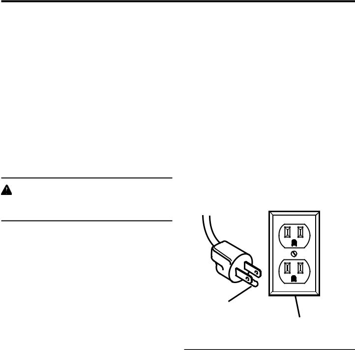
This tool is intended for use on a circuit that has an outlet like the one shown in Figure 1. It also has a grounding pin like the one shown.
GROUNDING
PIN
COVER OF GROUNDED
OUTLET BOX
Fig. 1
7

GLOSSARY OF TERMS
Base
Large rectangular plate that secures the drill press to a benchtop or other sturdy, level surface.
Chip
The material extracted from the hole in a drilling operation.
Chuck
The clamping device at the end of the spindle that secures the drill bit.
Chuck Key
A fitted key used to tighten and loosen the chuck.
Column
Large perpendicular rod that supports the work table and drill press head assembly.
Depth Stop
Adjustment control which allows the operator to control the depth of the hole in a drilling operation.
Drill Bit
Fluted cutting tool used in a drilling operation.
Head Assembly
The assembly at the top of the column which houses the motor, quill, and spindle.
Feed
The speed and force with which the drill bit is lowered into the workpiece.
Feed Handles
Three handles attached to the quill which allow the operator to lower the chuck and bit during a drilling operation.
Motor Pulley
Agrooved,conicalpulleydrivenbythemotorandresponsible for driving the spindle pulley by means of a belt.
Pilot Hole
A small hole drilled in a workpiece that serves as a guide for drilling large holes accurately.
Quill
Also known as the Feed Shaft. Responsible for lowering the chuck and bit into the workpiece and regulating the depth of the hole in a drilling operation.
Spindle
The rotating shaft upon which the chuck is attached.
Spindle Pulley
Agrooved,conicalpulleyresponsibleforrotatingthespindle. The spindle pulley is driven by the motor pulley by means of a belt.
Workpiece
The object into which a hole is to be drilled.
Worktable
Flat, level surface supported on the column and able to be positionedatvariousanglesverticallyonthecolumninorder to accommodate different size workpieces.
8

FEATURES
PRODUCT SPECIFICATIONS
n Input.......................... |
120V, 60 Hz, AC Only, 8 Amperes |
n Motor ................................................... |
1/2 HP Induction |
n No Load Speed....................................... |
300-3100/min. |
n Net Weight.......................................... |
158.4 lbs. (72 kg) |
n Number of Speeds |
.....................................................12 |
n Chuck Size.............................................. |
5/8 in. (1.6 cm) |
n Spindle Travel ..................................... |
3 -3/4 in. (9.5 cm) |
n Overall Height............................... |
65 - 1/2 in. (166.4 cm) |
|
BELT |
|
|
|
|
TENSION |
LIGHT |
|
|
BELT |
LOCK |
|
||
ON-OFF |
BELT TENSION |
|||
HANDLE |
||||
GUARD |
SWITCH |
|||
|
HANDLE |
|||
|
|
|
||
|
DRILL |
|
|
|
|
ON-OFF |
|
CHUCK KEY |
|
|
SWITCH |
DEPTH |
|
|
|
|
|
||
STORAGE |
FEED |
SCALE |
|
|
TRAY |
HANDLE |
DEPTH |
HEAD LOCK |
|
|
|
SET SCREWS |
||
|
|
SCALE |
|
|
|
SPRING |
LOCK |
FEED HANDLE |
|
|
|
|||
|
CAP |
|
||
|
CHUCK |
|
||
|
|
COLUMN COLLAR |
||
|
|
|
||
|
TABLE |
|
|
|
|
|
|
TABLE |
|
|
|
TABLE |
ADJUSTMENT |
|
TABLE |
|
HANDLE |
||
|
LOCK |
|||
|
|
|||
SUPPORT |
|
|
RACK |
|
LOCK |
|
|
COLUMN
COLUMN SUPPORT
|
40 |
0 |
0 10 20 30 |
|
10 |
|
20 |
|
30 |
|
40 |
BASE
TABLE
BEVEL
LOCK
BEVEL SCALE |
Fig. 2 |
|
9

FEATURES
KNOW YOUR DRILL PRESS
See Figure 2.
Before attempting to use your drill press, familiarize yourself with all operating features and safety requirements.
WARNING:
Do not allow familiarity with your machine to make you careless. Remember that a careless fraction of a second is sufficient to inflict severe injury.
BELT GUARD
Covers pulleys and belt during operation of drill press.
BELT TENSION LOCK HANDLE
Tightening handle locks motor bracket support to maintain correct belt distance and tension.
BELT TENSION HANDLE
Turn handle counterclockwise to apply tension to belt, turn handle clockwise to release belt tension. Refer to section “AssemblyTo Install the Idler Pulley and To Tension the Belts”.
HEAD LOCK SET SCREWS
Lock the head to the column. Always have them locked in place while operating the drill press.
FEED HANDLE
For moving the chuck up or down. One or two of the handles may be removed if necessary whenever the workpiece is of such unusual shape that it interferes with the handles.
COLUMN COLLAR
Holds the rack to the column. Rack remains movable in collar to permit table support movements.
TABLE ADJUSTMENT HANDLE
Turn clockwise to elevate table. Table support lock must be released before operating crank.
RACK
Combines with gear mechanism to provide easy elevation of table by hand operated table adjustment handle.
BASE
Supports drill press. For additional stability, holes are provided in base to bolt drill press to floor.
COLUMN SUPPORT
Supports column, guides rack, and provides mounting holes for column to base.
TABLE
Provides working surface to support workpiece.
DEPTH SCALE
Shows depth of hole being drilled in inches and millimeters.
DEPTH SCALE LOCK
Locks the depth scale to selected depth.
CHUCK
Holds drill bit or other recommended accessory to perform desired operations.
TABLE BEVEL LOCK
Locks the table in any position from 0°- 45°.
TABLE LOCK
Table can be rotated in various positions and locked.
BEVEL SCALE
Shows degree table is tilted for bevel operations. Scale is mounted on table support. It is to be used for quick reference where accuracy is not critical.
TABLE SUPPORT LOCK
Tightening locks table support to column. Always have it locked in place while operating the drill press.
STORAGE TRAY
Conveniently holds drill bits and other accessories.
ON-OFF SWITCH
Has locking feature. This feature is intended to prevent unauthorized and possible hazardous use by children and others. Insert key into switch.
10
 Loading...