


K-2000 Municipal Sewer
Cleaning Machine
OPERATOR’S
MANUAL
•Pour français voire page 11
•Para ver el castellano vea la paginá 23
IMPORTANT
For your own safety, before |
|
assembling and operating |
|
this unit, read this Operator’s |
|
Manual carefully and com- |
Kollmann |
pletely. Learn the operation, |
|
hazards peculiar to this unit. |
|
applications and potential |
|

K-2000 Municipal Sewer Cleaning Machine |
|
Table of Contents |
|
Recording Form for Machine Model and Serial Number............................................................................................ |
1 |
General Safety Information |
|
Work Area Safety ........................................................................................................................................................ |
2 |
Personal Safety ........................................................................................................................................................... |
2 |
Tool Use and Care ...................................................................................................................................................... |
2 |
Service ........................................................................................................................................................................ |
2 |
Specific Safety Information |
|
Machine Safety............................................................................................................................................................ |
3 |
Description, Specifications and Standard Equipment |
|
Description .................................................................................................................................................................. |
4 |
Specifications .............................................................................................................................................................. |
4 |
Standard Equipment.................................................................................................................................................... |
4 |
Accessories ................................................................................................................................................................. |
4 |
Operating Instructions |
|
Preparing Machine for Cable Operation...................................................................................................................... |
4 |
Starting Engine/Generator........................................................................................................................................... |
6 |
Operating Machine Using Cables................................................................................................................................ |
6 |
Removing Cable from Pipeline.................................................................................................................................... |
7 |
Stopping Engine/Generator......................................................................................................................................... |
7 |
Preparing Machine for Rod Operation......................................................................................................................... |
7 |
Operating Machine Using Rods .................................................................................................................................. |
7 |
Stopping Engine/Generator......................................................................................................................................... |
8 |
Maintenance Instructions |
|
Driver Jaws.................................................................................................................................................................. |
8 |
Clutch Casting and Main Bearing................................................................................................................................ |
8 |
Drive Chain.................................................................................................................................................................. |
8 |
Chain and Clutch......................................................................................................................................................... |
8 |
Wheels ........................................................................................................................................................................ |
8 |
Engine/Generator ........................................................................................................................................................ |
8 |
Wiring Diagram .............................................................................................................................................................. |
9 |
Lifetime Warranty.......................................................................................................................................... |
Back Cover |
ii |
Ridge Tool Company • Elyria, Ohio • U.S.A. |
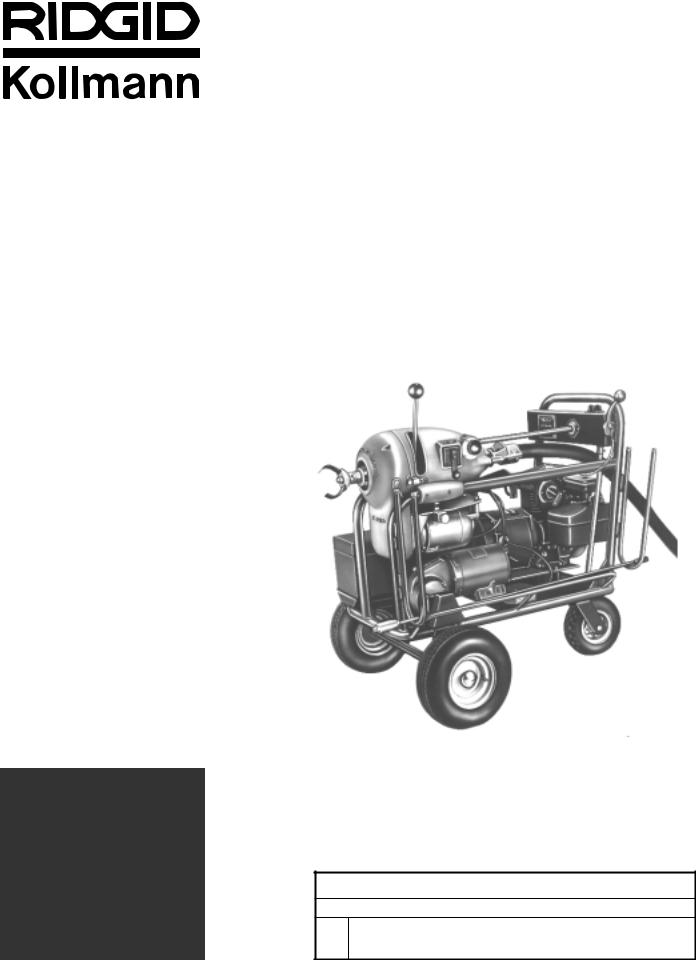
K-2000
Municipal Sewer Cleaning
Machine
IMPORTANT
For your own safety, before assembling and operating this unit, read this Operator’s Manual carefully and completely. Learn the operation, applications and potential hazards peculiar to this unit.
Municipal Sewer Cleaning Machine
Record Serial Number below and retain product serial number which is located on nameplate.
Serial
No.

K-2000 Municipal Sewer Cleaning Machine
General Safety Information
WARNING
Read and understand all instructions. Failure to follow all instructions listed below may result in electric shock, fire, and/or serious personal injury.
SAVE THESE INSTRUCTIONS!
Work Area Safety
1.Keep your work area clean and well lit. Cluttered benches and dark areas invite accidents.
2.Do not operate in explosive atmospheres, such as in the presence of flammable liquids, gases, or dust. Engines create sparks which may ignite the dust or fumes.
3.Keep bystanders, children, and visitors away while operating a power tool. Distractions can cause you to lose control.
4.Keep the engine at least 1 meter (3 feet) away from buildings and other equipment during operation. Do not place flammable objects close to the engine. Procedures should be followed to prevent fire hazards and to provide adequate ventilation.
Personal Safety
1.Stay alert, watch what you are doing and use common sense when operating a power tool. Do not use tool while tired or under the influence of drugs, alcohol, or medications. A moment of inattention while operating power tools may result in serious personal injury.
2.Dress properly. Do not wear loose clothing or jewelry. Contain long hair. Keep your hair, clothing, and gloves away from moving parts. Loose clothes, jewelry, or long hair can be caught in moving parts.
3.Remove adjusting keys or switches before turning the tool ON. A wrench or a key that is left attached to a rotating part of the tool may result in personal injury.
4.Do not over-reach. Keep proper footing and balance at all times. Proper footing and balance enables better control of the tool in unexpected situations.
5.Use safety equipment. Always wear eye protection. Dust mask, non-skid safety shoes, hard hat, or hearing protection must be used for appropriate conditions.
Tool Use and Care
1.Store idle tools out of the reach of children and other untrained persons. Tools are dangerous in the hands of untrained users.
2.Maintain tools with care. Keep cutting tools sharp and clean. Properly maintained tools with sharp cutting edges are less likely to bind and are easier to control.
3.Check for misalignment or binding of moving parts, breakage of parts, and any other condition that may affect the tools operation. If damaged, have the tool serviced before using. Many accidents are caused by poorly maintained tools.
4.Use only accessories that are recommended by the manufacturer for your model. Accessories that may be suitable for one tool may become hazardous when used on another tool.
5.Keep handles dry and clean; free from oil and grease. Allows for better control of the tool.
Service
1.Tool service must be performed only by qualified repair personnel. Service or maintenance performed by unqualified repair personnel could result in injury.
2.When servicing a tool, use only identical replacement parts. Follow instructions in the Maintenance Section of this manual. Use of unauthorized parts or failure to follow maintenance instructions may create a risk of electrical shock or injury.
3.Follow instructions for lubricating and changing accessories. Accidents are caused by poorly maintained tools.
Specific Safety Information
The Operator’s Manual contains specific safety information and instructions for your protection against serious injuries including:
•Loss of fingers, hands, arms or other body parts if clothing or gloves get caught in the rods or other moving parts;
•Carbon monoxide poisoning;
•Burns due to fire or explosion;
•Eye injuries, including being blinded by the cable or thrown debris.
2 |
Ridge Tool Company • Elyria, Ohio • U.S.A. |

K-2000 Municipal Sewer Cleaning Machine
Read and follow safety labels on machine! Know the location and functions
of all controls before using this tool.
or clean out. Greater distances can result in cable twisting or kinking.
6.Use rear guide hose. Prevents cable from whipping and picking up debris.
 WARNING
Rods and cables may twist or kink. Fingers, hands, or other body parts can be crushed or broken. Carbon monoxide poisoning can occur if operated in a confined area.
•Wear mitts with rivets
•Keep sleeves and jackets buttoned
•Keep guards in place
•Wear safety glasses
•Use caution. Gas is extremely flammable and explosive under certain conditions
•Never run engine in enclosed or confined area
READ ABOVE WARNING CAREFULLY!
Machine Safety
1.Wear leather mitt provided with the machine. Never grasp a rotating rod or cable with a rag or loose fitting cloth glove. It could become wrapped around the rod and cause serious injury.
2.Never operate machine with guards removed.
Fingers can be caught in rotating parts.
3.Do not operate machine in REV (reverse).
Operating machine in reverse can result in rod or cable damage and is used only to back tool out of an obstruction.
4.Do not overstress cables. Keep one hand on the cable for control when the machine is running.
Overstressing cables may cause twisting or kinking and result in serious injury.
5.When using cables, position machine within two feet of inlet. Use front end guide hose when it is difficult to locate the machine near the access
7.Operate machine from the side with the FOR/OFF/REV SWITCH. Allows for better control of the machine.
8.Disconnect spark plug wire. Spark plug wire should be removed when working on machine or engine to prevent accidental starting.
9.Operate rodder properly. Do not operate with more than 20 feet of rod between machine and manhole. This will minimize the possibility of kinking rods. The arcing of rod at manhole should not exceed 3 feet. When striking an obstacle that causes the tool to “hang-up”, do not attempt to “force” the machine by manually pushing on the exposed rods. This will cause kinking and whipping of the rods which could cause serious injury. Do not uncouple rods that are in a stressed condition. Read operating instructions carefully.
10.Do not overstress rods. Overstressing rods because of obstruction can be dangerous to operators, as rods may twist or kink. Do not use badly worn or bent rods.
11.Use caution when handling gasoline. Refuel in well-ventilated area. Do not overfill fuel tank and do not spill fuel. Make sure tank cap is closed properly. Gasoline is extremely flammable and is explosive under certain conditions.
12.Never run the engine in an enclosed or confined area. Exhaust contains poisonous carbon monoxide gas; exposure may cause loss of consciousness and may lead to death. Exhaust also contains chemicals that the state of California believes may cause cancer or reproductive harm.
13.Be careful not to touch the muffler while it is hot. To avoid severe burns or fire hazards, let the engine cool before transporting or storing it indoors.
The muffler becomes very hot during operation and remains hot for a while after stopping the engine.
14.Be careful when cleaning drains where cleaning compounds have been used. Avoid direct contact with skin and eyes. Serious burns can result from some drain cleaning compounds.
15.Machine is made to clean drain lines. Follow instructions in operator’s manual on machine uses.
Other uses may increase the risk of injury.
SAVE THESE INSTRUCTIONS!
Ridge Tool Company • Elyria, Ohio • U.S.A. |
3 |
K-2000 Municipal Sewer Cleaning Machine
Description, Specifications and
Standard Equipment
Description
The RIDGID/Kollmann K-2000 Municipal Sewer Cleaning Machine is a completely self-powered machine for cleaning lines and sewer mains of small communities, factory complexes, and shopping centers. It operates at two speeds, one for cable and one for rod.
Specifications
Standard Equipment
Rod Driver ...................... |
B-1821 |
Tool Adapter .................. |
A-2704 |
Tool Box.......................... |
Contains 1 Clutch Handle and |
|
1 quart of engine oil. A-3 |
Glove (L.H.) .................... |
A-1 |
Glove (R.H.) .................... |
A-2 |
Rod Turner...................... |
R-0 |
Capacity |
Accessories |
|
Cable |
...........................4″ through 12″ lines to 250′ |
Rod .............................. |
24″ mains through 500′ |
See Ridge Tool Main Product Catalog for machine accessories.
Dual Speed Drive |
|
Sectional Cable............ |
250 rpm |
Solid Rod ..................... |
60 rpm |
Clutches |
|
Instant-acting Clutch .... |
for driving Cable or Rods |
Propulsion Clutch......... |
for propelling machine when |
|
using Rods |
Switches |
|
Rod & Cable ................ |
FOR/OFF/REV SWITCH |
|
heavy-duty, lever-type |
Propulsion.................... |
FOR/OFF/REV SWITCH |
|
heavy-duty, toggle type |
Manual |
|
Cable Counter................. |
for Cable or Rods |
Stationary |
|
Positioner Arm ................ |
lowers manually to raise Front |
|
Wheels when using Cable |
Engine/Generator............ |
1500 watt, air-cooled 115 volt, |
|
60 Hz., Engine 3.8 h.p., 3600 |
|
rpm (Instruction Manual in |
|
Tool Box) |
|
NOTE! Use only leaded or |
|
low-lead gasoline in |
|
engine. |
Motors |
|
For Spinning Cable |
|
and Rod ....................... |
Universal, 1/2 h.p., 115 volt, |
|
60 Hz. |
For propulsion drive ..... |
1/6 h.p., 115-230 volt, single |
|
phase, 60 Hz., gear motor |
Length ............................. |
44″ |
Width............................... |
31″ |
Height.............................. |
361/2″ |
Weight with |
|
Standard Equipment ...... |
393 lbs. |
Operating Instructions
Preparing Machine for Cable Operation
1.Position sewer cleaning machine about two feet from manhole or other inlet.
2.Engage drive clutch and lock rear wheel (Figure 9) in straight position for stability. Unplug gear motor from engine/generator (Figure 3).
3.Release two latches (Figure 3) and remove guard on front of machine.
4.Pull ratchet knob (Figure 3) on motor table and raise table. Lock in highest position by giving ratchet knob one-half turn.
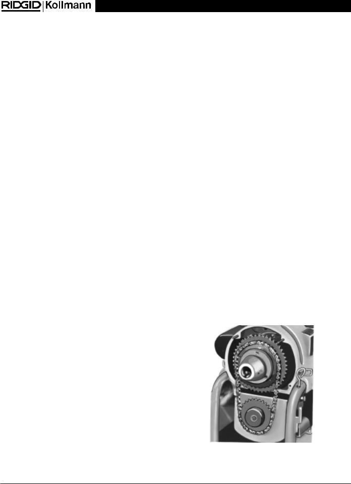
5.Set machine for high speed (normal cable operation) by shifting the power drive chain (Figure 1) to the small sprocket.
Figure 1 – Power Drive Chain on Small Sprocket
4 |
Ridge Tool Company • Elyria, Ohio • U.S.A. |
K-2000 Municipal Sewer Cleaning Machine
Clutch Handle |
Clutch Casting |
Cable Counter |
|
||
|
|
Guard
FOR/OFF/REV
Switch
Latch (2)
|
Guide Hose |
Motor Table |
|
Ratchet Knob |
Engine/Generator |
|
|
|
Gear Motor Plug |
Drive Motor |
Rear Wheel |
|
|
|
Front Wheel (2) |
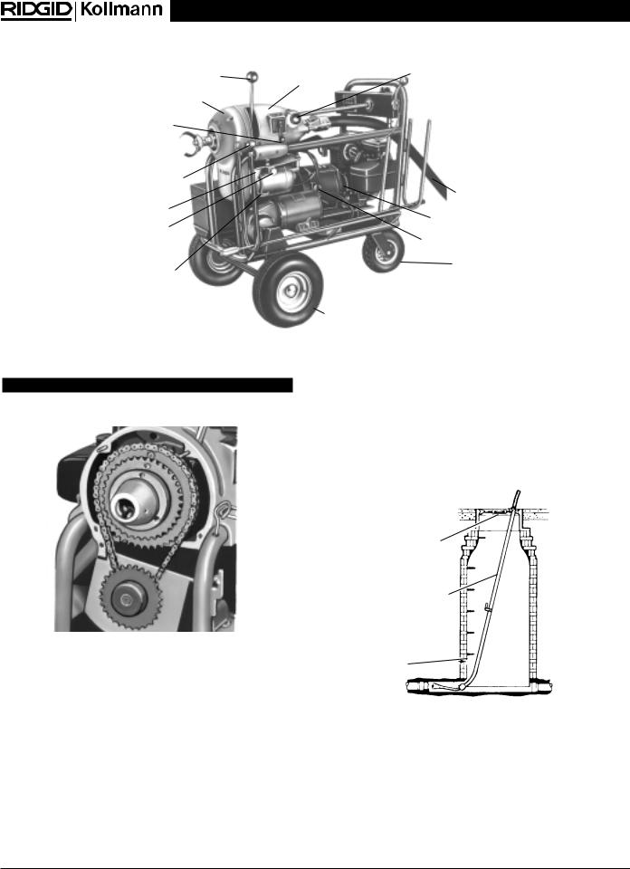
Figure 3 – K-2000 Machine with Cable Guide Hose and Clutch Handle in Clutch Casting
WARNING
Never change power drive chain from one sprocket to the other with engine/generator running.
Figure 2 – Power Drive Chain on Large Sprocket
6.Pull ratchet knob again to drop motor table into position, making sure chain slack is taken up. Put ratchet knob in LOCK POSITION.
7.Put machine guard back in place.
8.Screw clutch handle (Figure 3) into clutch casting.
9.Attach cable guide hose (Figure 3).
NOTE! If inlet is not a manhole, disregard steps 10 through 12.
10.Set telescoping manhole guide pipe (Figure 4) for depth of manhole. Place turnbuckle into manhole opening.
11.Insert first cable through manhole guide pipe and attach tool.
12.Put guide pipe into manhole and secure with “J” bolt to turnbuckle of guide pipe.
13.Attach next length of cable and feed from front through machine and through rear guide hose.
Turnbuckle
No. A-17 Telescoping
Manhole Guide Pipe
Manhole
Figure 4 – Telescoping Manhole Guide Pipe
Ridge Tool Company • Elyria, Ohio • U.S.A. |
5 |
K-2000 Municipal Sewer Cleaning Machine
Manhole
Guide Pipe
Rear Guide |
|
Hose |
Turnbuckle |
Figure 5 – Cable Operation
Starting Engine/Generator
CAUTION
Make sure engine crankcase is filled to indicated level with SAE-30 Oil.
1.Fill tank with regular gasoline.
2.Open gas shut-off valve.
3.Position FOR/OFF/REV SWITCH in OFF position.
4.Put ON/OFF SWITCH to ON position and close choke.
5.Pull starter rope. Engine should be running after two or three pulls.
6.Open choke when engine catches. Warm up engine for three minutes.
NOTE! For any reason engine does not start, refer to power plant instruction manual in tool box.
Operating Machine Using Cables
1.Place FOR/OFF/REV SWITCH (Figure 3) in FOR position.
2.Push on clutch handle maintaining firm pressure while feeding cable.
3.If tool meets heavy obstruction, release clutch handle, and place switch handle in OFF position.
4.When cable rotation stops, place switch handle in REV position and push firmly on clutch handle to back out and release tool.
5.When tool is free, place switch handle in OFF then FOR position to advance cable.
NOTE! Heavy and stubborn obstructions will require several repetitions of this procedure.
6.Release clutch handle and connect additional cables from rear as required.
7.As additional cables are added, keep count by advancing manual cable counter.
|
Clutch |
Propulsion |
Spring |
|
|
Handle |
Clutch Handle |
||
FOR/OFF/REV |
Loaded Pin |
|||
|
|
|||
Switch |
|
Rod Driver |
|
|
|
|
|
||
|
|
Nose Cone |
Latch |
|
Control Panel |
|
|
||
|
|
|
||
|
|
|
Guard |
|
|
|
|
Rod Driver |
|
|
|
|
Assembly |
|
Fuel |
|
|
|
|
Tank |
|
|
Motor Table |
|
|
|
|
||
Engine/Generator |
|
|
|
Pull Starter
Rear Wheel
Lock
Tool Box
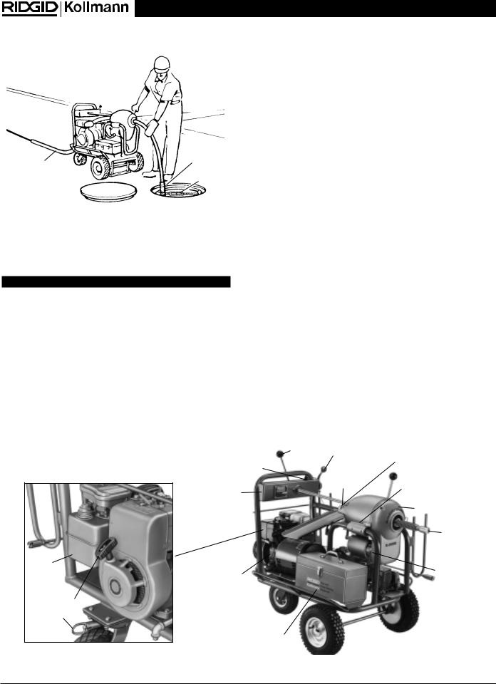
Figure 6 – K-2000 Machine with Rod Driver Assembly and Clutch Handle in Remote Control Housing
6 |
Ridge Tool Company • Elyria, Ohio • U.S.A. |

K-2000 Municipal Sewer Cleaning Machine
Removing Cable from Pipeline
1.Make sure motor FOR/OFF/REV SWITCH is in FOR position. Hold cable against edge of guide pipe and cable will screw itself out.
2.As each section comes through rear end of guide hose, uncouple it and set it aside for cleaning and storage.
Stopping Engine/Generator
To stop engine, push in ignition button.
Preparing Machine for Rod Operation
Rod Turner No. R-O
Raise |
Let Snap |
|
Back to |
||
Collar |
||
Position |
||
|
||
|
Rod |
Figure 7 – Hand Operated Rod Turner
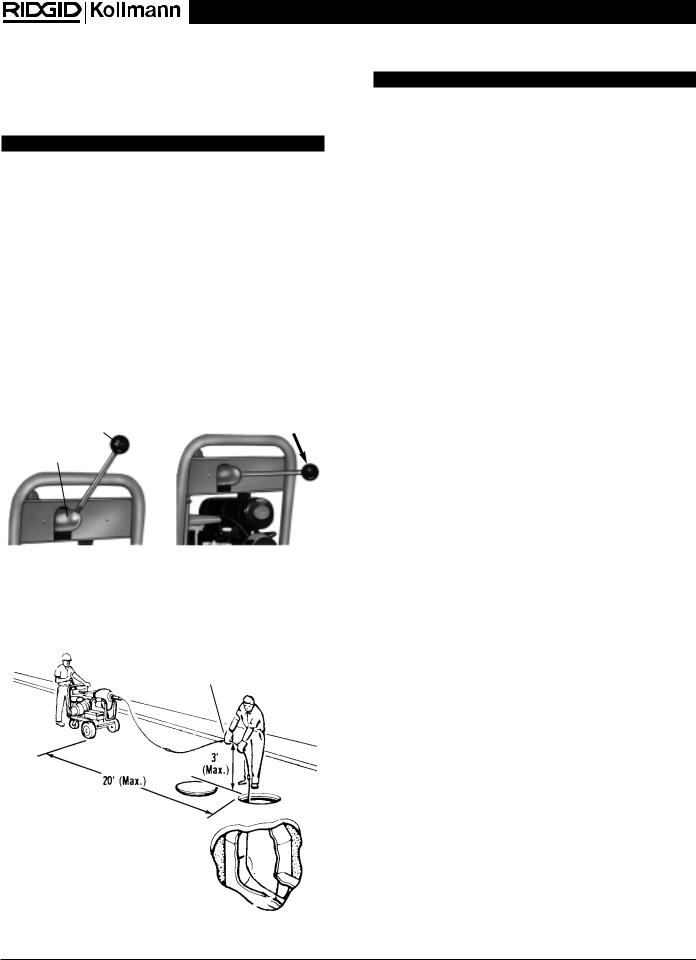
14.Couple enough rods together to extend out no more than 20 feet.
NOTE! Do not use manhole guide pipe or rear guide hose with rods.
1.Release two latches (Figure 6) and remove guard on front of machine.
2.Pull ratchet knob (Figure 3) on motor table and raise table. Lock in highest position by giving ratchet knob one-half turn.
3.Set machine for low speed by shifting the power drive chain (Figure 2) to the large sprocket.
4.Pull ratchet knob again to drop motor table into position, making sure chain slack is taken up. Put ratchet knob in lock position.
15.Couple rod to machine rod river assembly using RIDGID/Kollmann sectional rods with K-10 Speed Coupler (Figure 8).
Figure 8 – Coupling and Uncoupling Rods and Tools
5.Put machine guard back in place.
6.Screw clutch handle into remote control housing
(Figure 9).
7.Install rod driver assembly (Figure 6) through body and engage in nose cone. Be sure spring-loaded pin is engaged in nose cone.
8.When working through a manhole, attach auger or probing tool to tool adapter.
9.Couple enough rods to tool adapter to reach approximately 5 feet out of the manhole.
10.Holding onto both ends of a piece of rope, lower rod with attached tool into manhole, guiding tool towards lateral opening.
11.Use a hand operated rod turner and feed rod a little ways into lateral opening.
12.Release one end of rope and remove from manhole.
13.Remove rod turner (Figure 7).
NOTE! The K-10 Speed Coupler is the fastest, easiest method of changing tools and Rods. Simply snap male and female together and they are locked. To disconnect, insert Coupling Pin Key and slip apart. Speed Couplers can be added to all existing tools and Rods.
16. Lock rear wheel with locking pin (Figure 3).
Operating Machine Using Rods
NOTE! When working through manhole, 2 men are required. Machine operator and rod handler at manhole.
WARNING
Make certain that rod handler is wearing standard equipment leather gloves with riveted palms. Use no substitute.
1.Place rod rotating FOR/OFF/REV SWITCH (Figure 3) in FOR position.
2.Hold clutch handle (Figure 9) down maintaining firm pressure to rotate rods.
3.Move FOR/OFF/REV SWITCH (Figure 6) on control panel to FOR position.
4.Drive machine forward by rotating propulsion clutch handle (Figure 6) forward to horizontal position.
Ridge Tool Company • Elyria, Ohio • U.S.A. |
7 |
K-2000 Municipal Sewer Cleaning Machine
5.As machine moves forward and rod handler should push downward on rod with rod guided between thumbs and palms of hands with fingers extended.
WARNING
The arcing of rod at manhole should not exceed 3 feet. This will prevent rod handler from losing control of rotating rod.
6.When machine is approximately 8 feet from manhole, release clutch handle and place propulsion
FOR/OFF/REV SWITCH in OFF position.
7.Uncouple rod from rod driver assembly.
8.Place FOR/OFF/REV SWITCH in REV position.
9.Drive machine backwards about 10 feet by rotating propulsion clutch handle forward to horizontal position.
WARNING
If kinking of rod occurs move all people to rear of machine before reversing machine. Violent whipping action of rod could cause serious injury.
12.Drive machine backwards (steps 8 and 9) to release tool and then proceed through obstruction (steps 1 through 10) some distance to make sure line is clear.
NOTE! With a little practice operator will learn to go at pace which is most effective.
13.When completed, drive machine backwards to remove rod from sewer with rod rotating in forward direction.
Stopping Engine/Generator
Put ON/OFF SWITCH to OFF position.
10.Connect additional rods and continue feeding rods by following steps 1 through 10.
Clutch Handle |
Hold Down to |
|
Rotate Rods |
||
Remote Control |
||
|
||
Housing |
|
Figure 9 – Clutch Handle in Remote Control Housing
11.If tool gets “hung-up” in obstruction, release clutch handle and disengage propulsion clutch handle by rotating to vertical position.
Leather Gloves
(Standard Equipment)
WARNING!
Do not ever reverse machine to release a kink in rod until man at manhole is behind machine. Violent whipping action of rod could cause serious injury.
Maintenance Instructions
NOTE! If any maintenance is required other than that listed below take K-2000 to an authorized RIDGID Warranty Repair Center or return it to the factory.
Driver Jaws
Clean and lubricate driver jaws with oil after each use.
Clutch Casting and Main Bearing
Grease the clutch casting and main bearing every three months. Grease gear segment every three months.
Drive Chain
PROPULSION DRIVE CHAIN should be oiled every month. Check the propulsion unit (reduction gear unit) for proper oil level.
Chain and Clutch
Lubricate chain and clutch parts every month.
Wheels
The tires must carry 60 pounds of pressure at all times. Grease the wheels at fittings.
Engine/Generator
For maintenance instructions, refer to power plant instruction manual in tool box.
Lateral Opening 
Figure 10 – Operating Machine
8 |
Ridge Tool Company • Elyria, Ohio • U.S.A. |

K-2000 Municipal Sewer Cleaning Machine
Wiring Diagram
115V/60 Hz
Wiring Diagram
230V/50 Hz
Ridge Tool Company • Elyria, Ohio • U.S.A. |
9 |

K-2000 Municipal Sewer Cleaning Machine
10 |
Ridge Tool Company • Elyria, Ohio • U.S.A. |
 Loading...