


SR-60
Operator’s
Manual
SeekTech® SR-60
Pipe, Cable and Sonde Locator
Patents Pending
WARNING!
Read this operator’s manual
carefully before using this
tool. Failure to understand
and follow the contents of
this manual may result in
electrical shock, fire and/or
serious personal injury.

SeekTech SR-60
Table of Contents
GENERAL SAFETY INFORMATION........................................................................................................... 2
SR-60 COMPONENTS..................................................................................................................................5
INTRODUCTION TO THE SR-60.................................................................................................................6
GETTING STARTED ...................................................................................................................................... 6
DISPLAY ELEMENTS..................................................................................................................................... 6
SET UP .....................................................................................................................................................11
LINE TRACING WITH THE SR-60............................................................................................................. 13
ACTIVE LINE TRACING ...............................................................................................................................13
DEPTH WARNINGS...................................................................................................................................16
OPERATING TIPS FOR ACTIVE LINE TRACING ..............................................................................................17
PASSIVE LINE TRACING..............................................................................................................................20
OMNISEEK LOCATING................................................................................................................................21
SONDE LOCATING ................................................................................................................................... 22
LOCATION METHODS ................................................................................................................................. 23
TILTED SONDES ........................................................................................................................................24
MEASURING DEPTH (SONDE MODE)...........................................................................................................25
SIMULTRACE............................................................................................................................................. 25
CUSTOM USER FREQUENCIES.............................................................................................................. 28
MENUS AND SETTINGS ........................................................................................................................... 29
OPTIONAL FEATURES ................................................................................................................................31
MENU TREE .............................................................................................................................................. 35
OPERATING WITH THE DISTORTION LINE ....................................................................................................35
INFORMATIONAL LOCATING ........................................................................................................................36
NOTES ON ACCURACY ............................................................................................................................... 36
A BETTER WAY OF LOCATING............................................................................................................... 38
ADVANTAGES OF THE OMNIDIRECTIONAL ANTENNA..................................................................................... 38
SR-60 MAINTENANCE.............................................................................................................................. 39
SERVICE AND REPAIR................................................................................................................................40
ICONS AND SYMBOLS.............................................................................................................................41
GLOSSARY -- DEFINITIONS.........................................................................................................................42
TROUBLE SHOOTING GUIDE..................................................................................................................45
SPECIFICATIONS........................................................................................................................................ 46
DEFAULT SETTINGS................................................................................................................................... 46
STANDARD EQUIPMENT .............................................................................................................................46
OPTIONAL EQUIPMENT............................................................................................................................... 46
FREQUENCIES TABLE.................................................................................................................................46
MANUFACTURERS FREQUENCY TABLE........................................................................................................47
ii www.seektech.com Ridge Tool Company Elyria, Ohio U.S.A
SeekTech SR-60
SeekTech® SR-60
Pipe, Cable and Sonde Locator
SeekTech® SR-60
Record the Serial Number of your unit below and retain for your records.
See Information screen for serial number and software version.
Serial
Number
Software
Version
Ridge Tool Company Elyria, Ohio U.S.A www.seektech.com 1
SeekTech SR-60
General Safety Information
WARNING
Read and understand all instructions. Failure to
follow all instructions listed below may result
in electric shock, fire, and/or serious personal
injury!
SAVE THESE INSTRUCTIONS
Work Area Safety
Keep your work area clean and well
•
lit. Cluttered benches and dark areas
may cause accidents.
• Do not operate electrical devices or
power tools in explosive
atmospheres, such as in the
presence of flammable liquids,
gases, or heavy dust. Electrical
devices or power tools create sparks,
which may ignite the dust or fumes.
• Keep bystanders, children, and
visitors away while operating tool.
Distractions can cause you to lose
control.
Electrical Safety
Do not operate the system with
•
electrical components removed.
Exposure to internal parts increases the
risk of injury.
• Avoid exposure to rain or wet
conditions. Keep battery out of direct
contact with water. Water entering
electrical devices increases the risk of
electric shock.
• Do not probe high voltage lines.
Battery Precautions
Use only the size and type of battery
•
specified. Do not mix cell types (e.g.
do not use alkaline with
rechargeable). Do not use partly
discharged and fully charged cells
together (e.g. do not mix old and new).
• Recharge batteries with charging
units specified by the battery
manufacturer. Using an improper
charger can overheat and rupture the
battery.
• Properly dispose of the batteries.
Exposure to high temperatures can
cause the battery to explode, so do not
dispose of in a fire. Some countries
have regulations concerning battery
disposal. Please follow all applicable
regulations.
Personal Safety
Stay alert, watch what you are doing,
•
and use common sense. Do not use
diagnostic tools while tired or under the
influence of drugs, alcohol, or
medications. A moment of inattention
while operating diagnostic instruments
may result in serious personal injury.
• Gloves should always be worn for
health and safety reasons. Sewer
lines are unsanitary and may contain
harmful bacteria and viruses.
• Do not overreach. Keep proper
footing and balance at all times.
Proper footing and balance enables
better control of the tool in unexpected
situations.
• Use safety equipment. Always wear
eye protection. Dust mask, non-skid
safety shoes, hardhat, or hearing
protection must be used for appropriate
conditions.
• Use proper accessories. Do not place
this product on any unstable cart or
surface. The product may fall causing
serious injury to a child or adult or
serious damage to the product.
• Prevent object and liquid entry.
Never spill liquid of any kind on the
product. Liquid increases the risk of
electrical shock and damage to the
product.
• Avoid Traffic. Pay close attention to
moving vehicles when using on or
near roadways. Wear visible clothing
or reflector vests. Such precautions
may prevent serious injury.
2 www.seektech.com Ridge Tool Company Elyria, Ohio U.S.A
SeekTech SR-60
SR-60 Use and Care
•
Use equipment only as directed. Do
not operate the SR-60 unless you have
read the operator’s manual.
• Do not immerse the antennas in
water. Store in a dry place. This will
reduce the risk of electric shock and
instrument damage.
• Store idle equipment out of the
reach of children and other
untrained persons. Equipment is
dangerous in the hands of untrained
users.
• Maintain the instrument with care.
Properly maintained diagnostic
instruments are less likely to cause
injury.
• Check for breakage of parts, and any
other conditions that may affect the
SR-60’s operation. If damaged, have
the instrument serviced before using.
Many accidents are caused by poorly
maintained tools.
• Use only accessories that are
recommended by the manufacturer
for the SR-60. Accessories that may
be suitable for one instrument may
become hazardous when used on
another.
• Keep handles dry and clean, and
free from oil and grease. Allows for
better control of the instrument.
• Protect against excessive heat. The
product should be situated away from
heat sources such as radiators, heat
registers, stoves, or other products that
produce heat.
Service
Diagnostic instrument service must
•
be performed only by qualified repair
personnel. Service or maintenance
performed by unqualified repair
personnel could result in injury.
• When servicing a diagnostic
instrument, use only identical
replacement parts. Follow instructions
in the maintenance section of this
manual. Use of unauthorized parts or
failure to follow maintenance
instructions may create a risk of
electrical shock or injury.
• Follow instructions for changing
accessories. Accidents are caused by
poorly maintained equipment.
• Provide proper cleaning. Remove
battery before cleaning. Do not use
liquid cleaners or aerosol cleaners. Use
a damp cloth for cleaning.
• Conduct a safety check. Upon
completion of any service or repair of
this product, ask the service technician
to perform safety checks to determine
that the product is in proper operating
condition.
• Damage to the product that requires
service. Remove the batteries and
refer servicing to qualified service
personnel under any of the following
conditions:
o If liquid has been spilled or objects
have fallen into product;
o If product does not operate normally
by following the operating
instructions;
o If the product has been dropped or
damaged in any way;
o When the product exhibits a distinct
change in performance.
CAUTION
Remove batteries entirely before shipping.
If you have any questions regarding the service or
repair of this machine, call or write to:
Ridge Tool Company
Technical Service Department
400 Clark Street
Elyria, Ohio 44035-6001
Tel: (800) 519-3456
E-mail:
www.ridgid.com
TechServices@ridgid.com
Ridge Tool Company Elyria, Ohio U.S.A www.seektech.com 3
SeekTech SR-60
DANGER
Important Notice
The SR-60 is a diagnostic tool that senses
electromagnetic fields emitted by objects
underground. It is meant to aide the user in locating
these objects by recognizing characteristics of the
field lines and displaying them on the screen. As
electromagnetic field lines can be distorted and
interfered with, it is important to verify the location
of underground objects before digging.
Several utilities may be underground in the
same area. Be sure to follow local guidelines
and one-call service procedures.
Exposing the utility is the only way to verify its
existence, location, and depth.
Ridge Tool Co., its affiliates and suppliers, will
not be liable for any injury or any direct,
indirect, incidental or consequential damages
sustained or incurred by reason of the use of
the SR-60.
In any correspondence, please give all the
information shown on the nameplate of your locator
including model number and serial number.
DANGER
Important Notice
Always insert and connect the earth grounding rods
before turning on the transmitter. Never pull out an
earth grounding rod as long as the generator is
switched on! Never pull the earth grounding rod or
disconnect the ground lead if the other lead is
connected to a utility.
4 www.seektech.com Ridge Tool Company Elyria, Ohio U.S.A
SeekTech SR-60
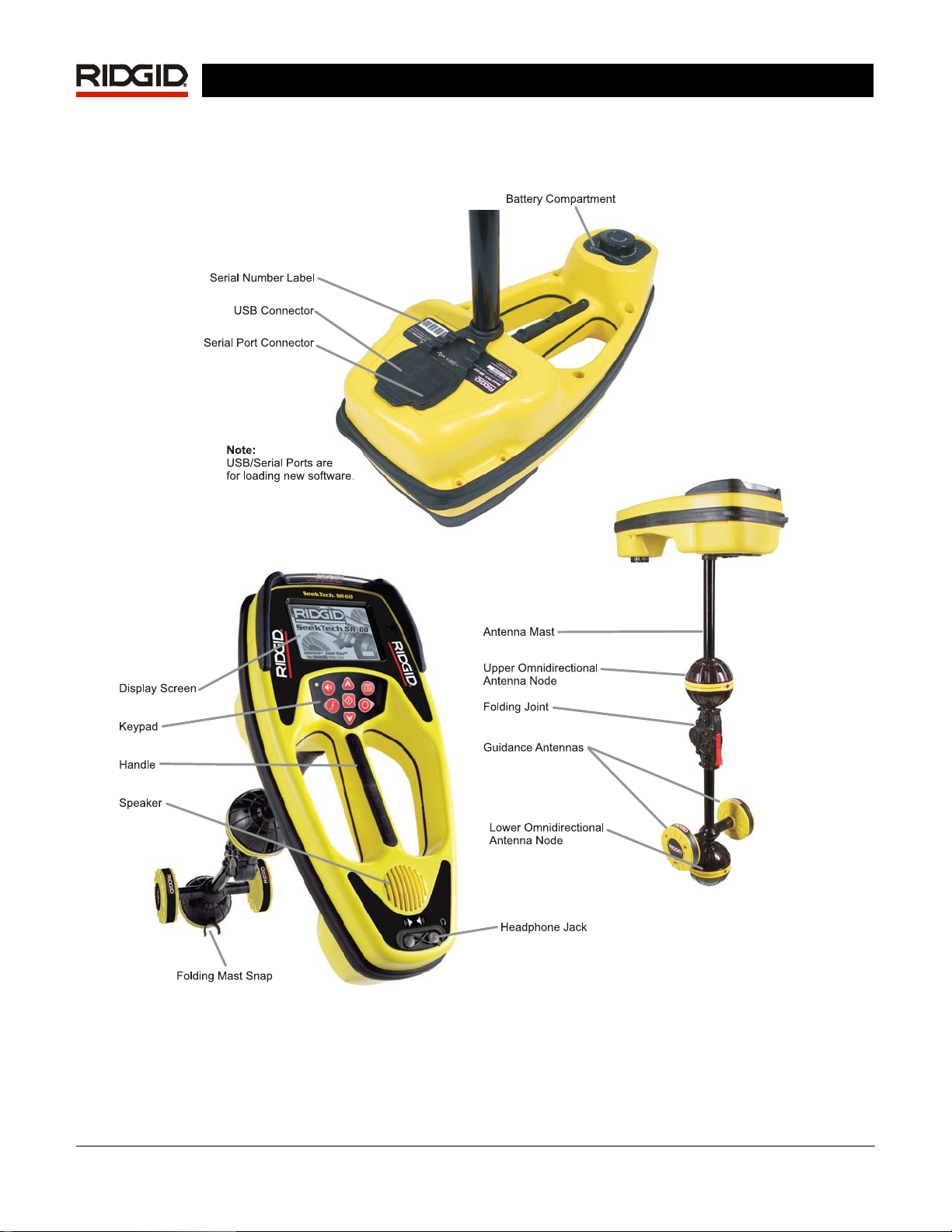
SR-60 Components
Figure 1: SR-60 Components
Ridge Tool Company Elyria, Ohio U.S.A www.seektech.com 5
SeekTech SR-60
Introduction to the SR-60
Getting Started
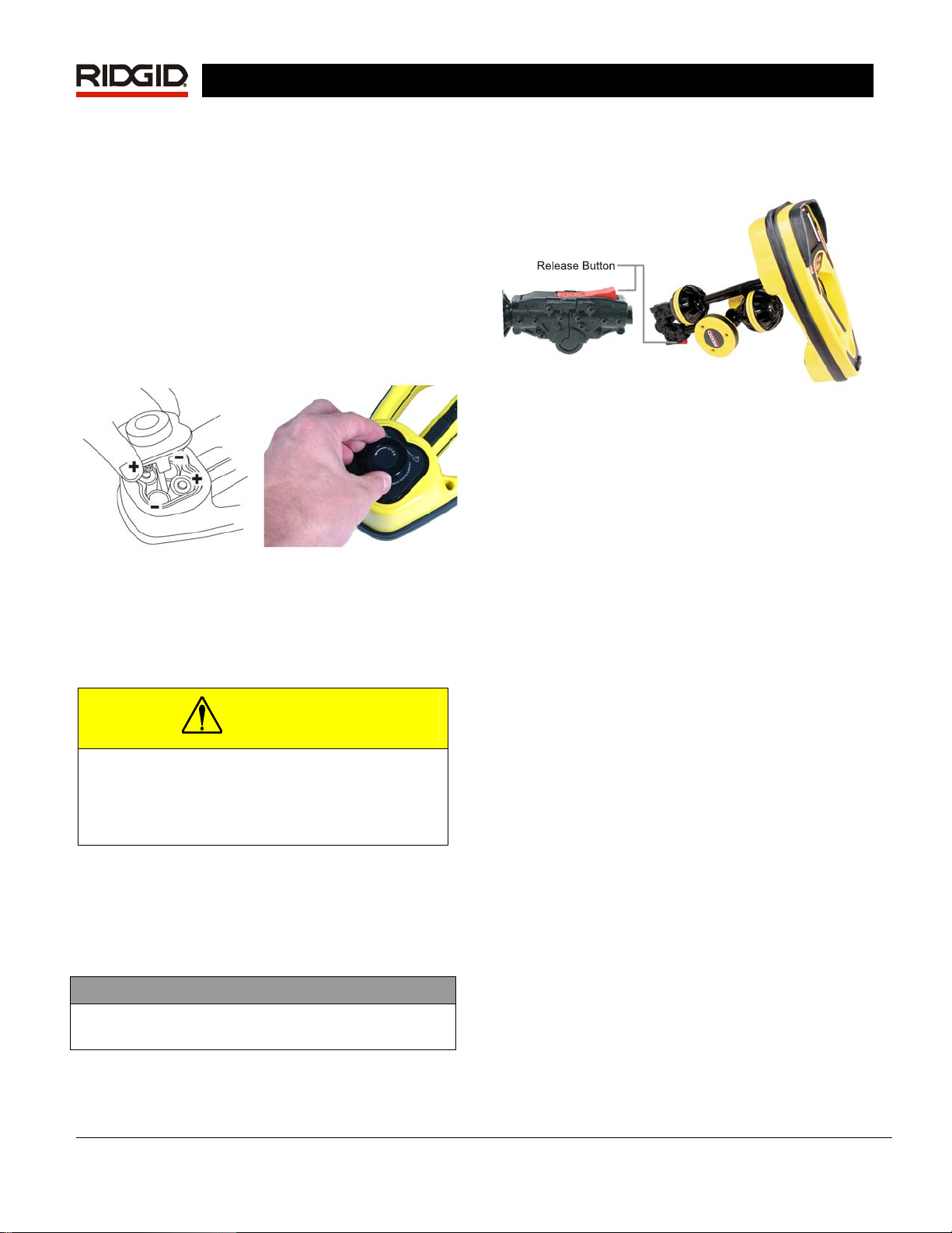
Installing/Changing Batteries
To install batteries into the SR-60, turn the unit over
to access the battery compartment. Turn the knob on
the battery cover counter clockwise. Pull straight up
on the knob to remove the cover. Insert the batteries
as shown on the inside decal and make sure they
drop to full contact. Fit the cover into the case and
turn the knob clockwise while lightly pressing down to
close. The battery cover can be installed in either
orientation.
Figure 2: Battery Case
When the SR-60 is powered on, it takes a few
seconds to check the batteries. Until then the battery
level will show as “empty”.
CAUTION
Do not allow debris or moisture into battery
compartment. Debris or moisture may short
the battery contacts, leading to rapid discharge
of the batteries, which could result in
electrolyte leakage or risk of fire.
Folding Mast
To begin operation, unfold the antenna mast and lock
the folding joint into place. When locating is
complete, press the red release lever to fold the
antenna mast for storage.
IMPORTANT
Do not snap or whip the SR-60 mast to open or
close it. Open it and close it by hand only.
NOTE: Avoid dragging the lower antenna node on
the ground while locating with the SR-60. It may
cause signal noise which will interfere with
results, and may eventually damage the antenna
Figure 3: Folding Antenna Mast and Release Butt on
SR-60 Modes
The SR-60 operates in three distinct modes. They
are:
1. Active Line Trace Mode, used when a
chosen frequency can be put onto a long
Note that the two Tracing modes, Active and Passive,
are identical except for the frequencies used. No
transmitter is used in Passive Trace mode.
conductor using a Line Transmitter, for
locating conductive pipes, lines, or cables.
2. Passive Trace Mode, used for tracing
electrical lines that are already carrying 60
Hz current (U.S.), 50 Hz current (Europe), or
radio frequencies.
3. Sonde Mode, used for locating Sondes in
pipes, conduits, or tunnels that are nonconductive or cannot otherwise be traced.
Display Elements
Beginning operators or experienced operators can
use the SR-60 with equal ease. While the SR-60
offers advanced features that make the most
complex locate easier, many of its features can be
turned off or hidden, making the SR-60 simple to use
in basic locating in uncomplicated situations.
The “basic features” of the SR-60 are on by default.
They can be customized easily to suit the user’s
requirements. The use of the various elements
displayed is covered in later sections of this manual.
.
6 www.seektech.com Ridge Tool Company Elyria, Ohio U.S.A
SeekTech SR-60
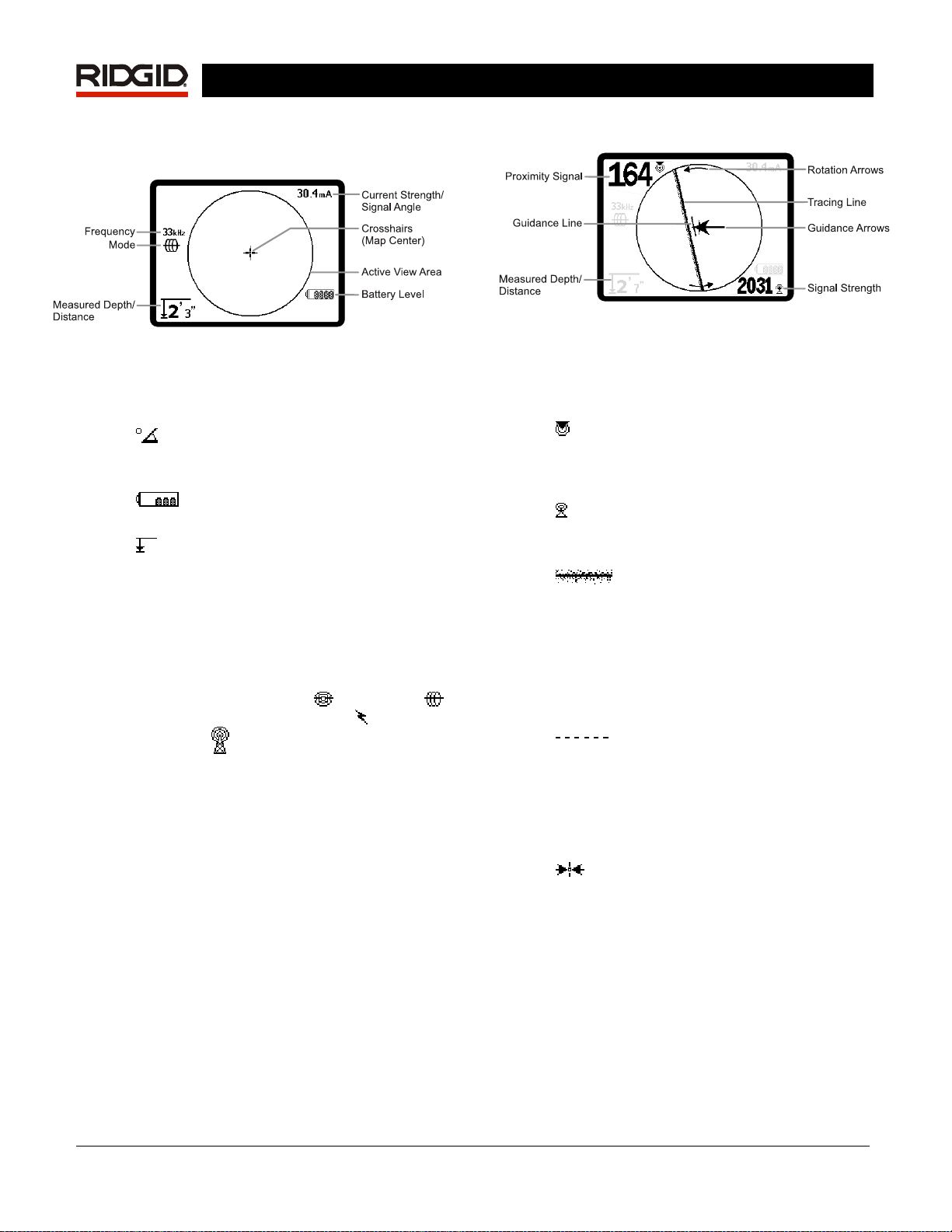
Common Display Elements
Figure 4: Common Display Elements
The display screen in Active Line Trace, Passive Line
Trace or Sonde mode will show the following
features:
•
•
•
• Mode– Icon for Sonde
• Frequency – Shows current frequency
• + Crosshairs (Map Center) - shows
Signal Angle: Field tilt from the
horizontal; angle toward the field’s center;
numeric value displayed in degrees.
Battery Level – Indicates level of
remaining battery capacity.
Measured Depth/Distance – Displays
the measured depth when receiver is
touching the ground directly over signal
source. Displays computed distance when
the antenna mast is pointed at a signal
source in some other manner. Displays
feet/inches (U.S.A. default) or meters
(European default).
, Line Trace ,
Power (Passive Line Trace)
Frequency
setting in hertz or kilohertz.
operator’s position relative to the target
center.
mode.
, or Radio
Display Elements: Line Trace Mode
Figure 5: Display Elements (Line Trace Mode)
In Active Line Trace Mode, the following features will
also be displayed:
Proximity Signal – Numerical indication
•
showing how close the signal source is to the
locator. Displays from 1 to 999. (Line Trace
modes only)
Signal Strength – Strength of signal as
•
sensed by the lower Omnidirectional
antenna.
•
represents the approximate axis of the
detected field. It represents detected
distortion in the field by appearing less
focused. (See page 33 for information on
setting the sensitivity and how to enable or
disable the distortion response in the Tracing
Line.)
•
distortion response of the Tracing Line is
disabled, a second line is shown, which
represents the signal from the upper antenna
node. By comparing the two lines, the user
can estimate the degree of distortion present
in a signal. (See page 35.)
•
Arrows serve to steer the operator toward the
center of the detected field, by showing when
the signals reaching the left and right
Guidance Antennas are out of balance or
equal. The two signals are equal when
crossing the center of an undistorted field. If
the signals are unequal, the Guidance
Arrows show which way the field appears to
be relative to the receiver.
Tracing Line – The Tracing Line
Distortion Line If the normal
Guidance Arrows The Guidance
mA Current Strength – Proportional to
•
current on the line. Switches to Signal Angle
when Signal Angle is greater than 35°.
Ridge Tool Company Elyria, Ohio U.S.A www.seektech.com 7
• Guidance Line Shows the alignment of the
target line and helps determine when the
locator is directly over the target line. It will
be longest when directly aligned with the
target line. Rotation Arrows will appear to
indicate which way the SR-60 should be
turned to align it with the field.
Note: The Tracing Line reflects the approximate axis
of the conductor being traced, but is modified by a
degree of “distortion” in the form of varying
cloudiness, or loss of focus, in the Tracing Line. The
Tracing Line will appear to grow unfocused in
proportion to the distortion in the field being detected.
It ranges from a clear line (no distortion present),
through slightly distorted, to moderately un-focused,
growing to a wide, cloud-like band of particles
depending on the degree of distortion in the detected
field. It represents the best possible calculation of the
location and bearing of the line combined with the
degree of distortion sensed by the receiver’s
Omnidirectional Antennas.
SeekTech SR-60
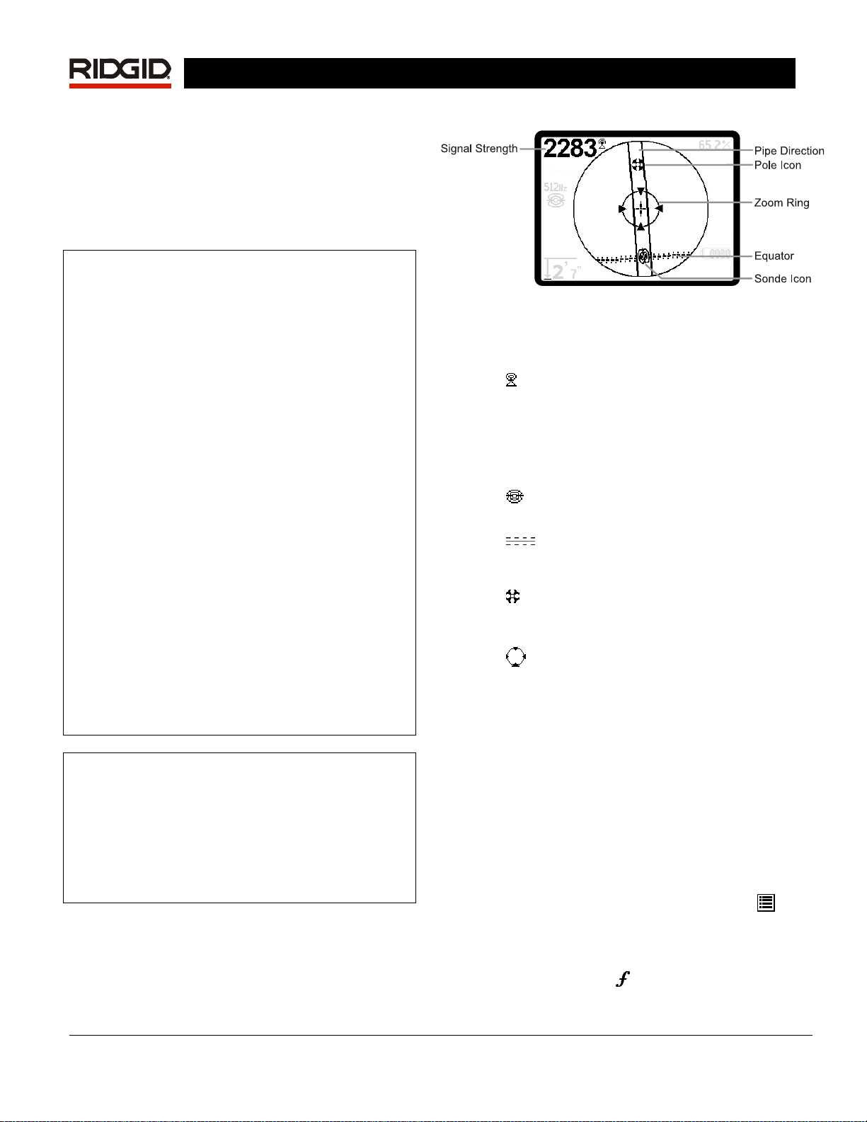
Display Elements: Sonde Mode
Figure 6: Display Elements: Sonde Mode
In Sonde mode, the screen elements include several
features that are unique to Sonde locating.
Signal Strength – Strength of signal as
•
sensed by the lower Omnidirectional
antenna.
| Pipe Direction – Represents the
• |
approximate direction of the pipe in which the
Sonde is lying.
When the distortion response of the tracing line is
turned off, a separate Distortion Line will be
displayed. The Distortion Line can be used to analyze
distortion when it is out of alignment with the Tracing
Line. (The dashed line can be disabled separately, as
well, which will leave a single Tracing Line displayed
with no distortion response).
The default setting is to have the distortion response
enabled in the Tracing Line. This incorporates the
information provided by these two lines into a single,
easy-to-read presentation, making the SR-60 easier
to use.
(For more information about distortion, see pages 33
and 39.)
Note: The screen elements in Passive Trace Mode
are the same as those seen in Active Line Trace
mode. Mode is determined by the type of target
source (Sonde or Line). For example, selecting the
512 Hz frequency from the Sonde mode section of
the frequency menu puts the SR-60 into Sonde
mode. (A frequency which appears in more than one
category, such as 33 kHz, must be selected from the
correct category).
•
•
•
•
The use of these features is described in the Active
Line Tracing, Passive Line Tracing, and Sonde
Locating sections.
Sonde Icon – Appears when
approaching the location of a Sonde.
Equator – Represents the mid-line of
the Sonde’s field perpendicular to the axis of
the Poles. (See page 26).
Pole Icon – Represents the location of
either of the two Poles of the Sonde’s dipole
field. (See page 26).
Zoom Ring – Appears when the locator
moves close to a Pole.
Default Frequencies
The Master Frequency Menu contains a large set of
frequencies, but only some of these are made
currently available. They are made “Currently
Available” by checking them in the Master Frequency
Menu.
The frequencies which are currently available will
appear on the Main Menu when the Menu Key
pressed.
is
Currently available frequencies can be checked in the
Main Menu, in which case they will appear when
using the Frequency Key
. If they are unchecked in
8 www.seektech.com Ridge Tool Company Elyria, Ohio U.S.A
SeekTech SR-60
the Main Menu, they will not appear when using the
Frequency Key to cycle through frequencies.
Frequencies which appear in the Main Menu and are
checked for activation are called “Checked-Active”.
Frequencies that are “Checked-Active” can be cycled
through simply by pressing the Frequency Key
Figure 7). A frequency chosen by pressing the
(see
Frequency Key becomes the “In Use” frequency.
Frequencies currently available by default include:
Sonde Mode
• 512 Hz*
Active Line Trace Mode:
• 128 Hz*
• 1 kHz*
• 8 kHz*
• 33 kHz*
• 93 kHz*
• 262 kHz*
Power (Passive Line Trace Mode):
• 60 Hz (9
• < 4 kHz *
Radio Frequency
• 4 kHz—15 kHz (L) *
• 15 kHz – 35kHz (H) *
OmniSeek (multi-range <4kHz – 35kHz)*
(* = Checked-Active Frequencies)
th
) *
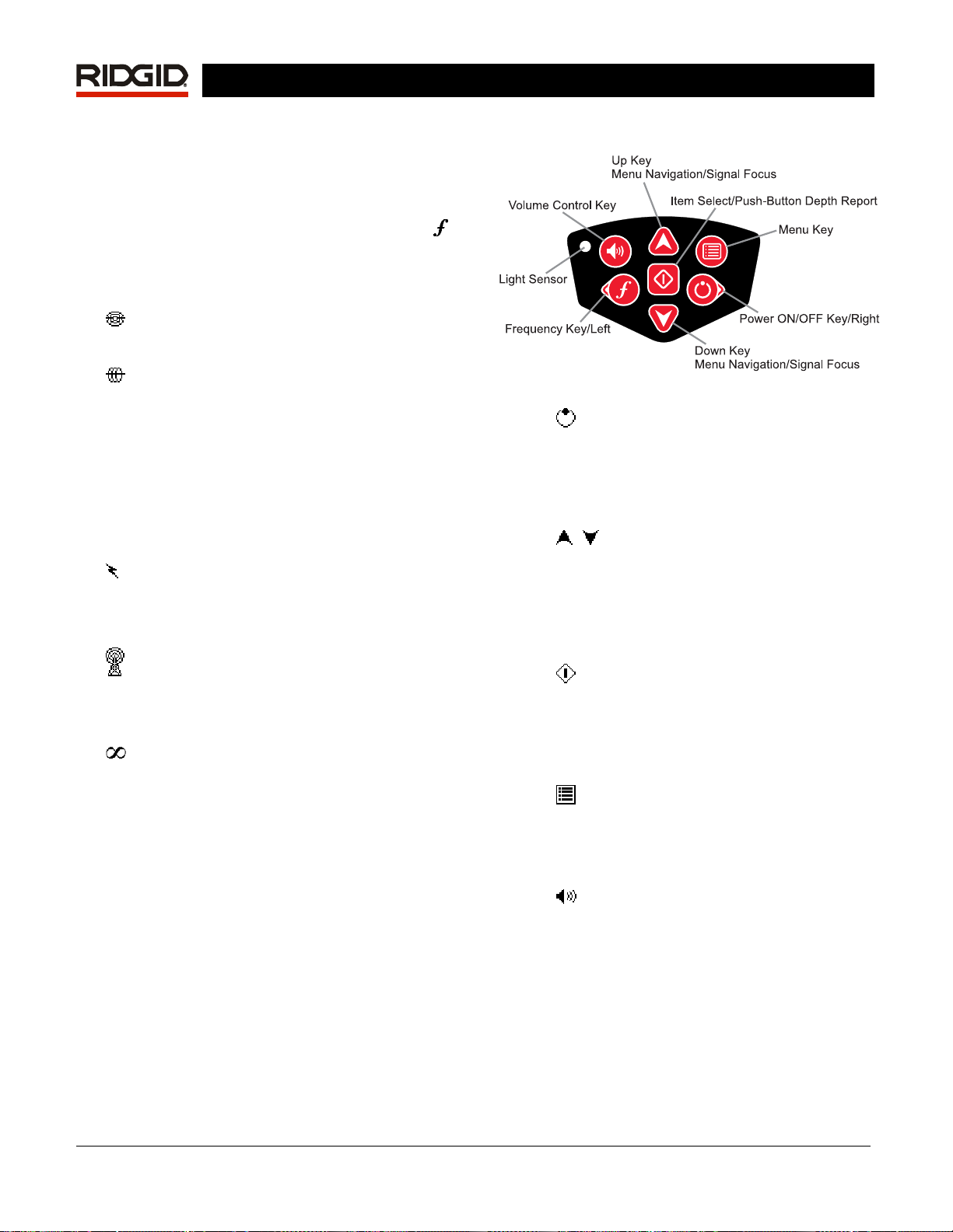
Keypad
Figure 7: Keypad
• Power/Right Key – Powers SR-60 on.
Powers the SR-60 down after a 3-second
countdown. The countdown can be
interrupted before shutdown by pressing any
key. Used to move to the right in some
screens.
Up and Down Keys – Used for
•
locating choices during menu selection; used
for setting volume level when the Volume
Control Key has been pressed. If Signal
Focus is activated, the Up and Down Keys
will change the Signal Focus setting up and
down.
•
•
Select Key – Used to make a choice
during Menu selection; in normal operation,
to force a Measured Depth reading and recenter audio tone. Can be used to force a
“quick-check” trace-line and Measured Depth
display.
Menu Key – Used to display a “tree” of
choices including frequency selections,
display element choices, brightness and
contrast, and restoring default settings. In a
menu, will move up one level.
•
Volume Control Key – Used to raise or
lower the volume setting; will cycle the
volume by steps, increasing to maximum and
then mute. Pressing the Volume Key opens
the volume control panel if it is closed. When
open, the control panel will close after ten
seconds if no keys are pressed. Volume can
also be raised and lowered using the Up and
Down Keys when the Volume screen is open.
Ridge Tool Company Elyria, Ohio U.S.A www.seektech.com 9
• Frequency / Left Key – Used to set the
In-Use Frequency of the SR-60 from the set
of Checked-Active frequencies. Each short
press cycles to the next Checked-Active
frequency. (The list of frequencies that have
been set to Checked-Active status can be
modified via the Menu Key.)
SeekTech SR-60
This indicates that the batteries need to be changed
and that the unit will soon shut down. A tone will
sound at ten-minute intervals.
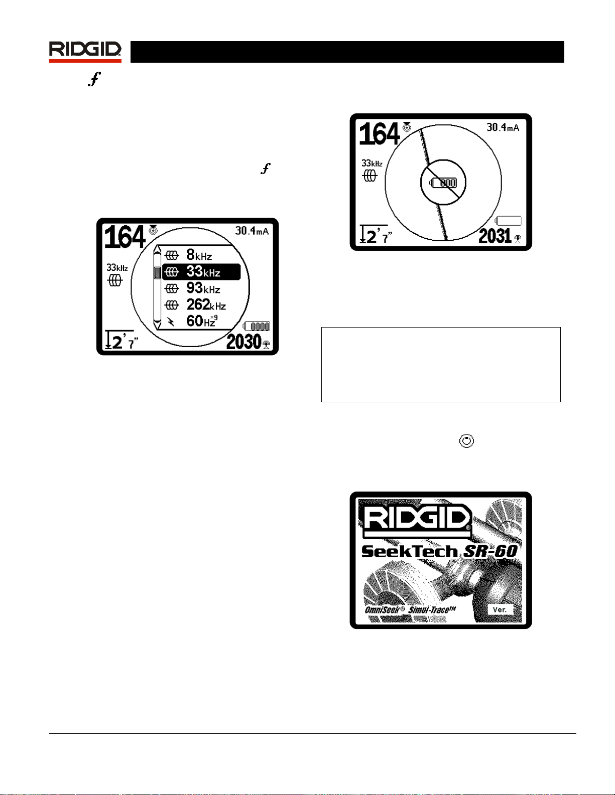
A long press on the Frequency Key
display a scrollable list of all currently active
frequencies to choose from, by highlighting
and pressing Select again.
Figure 8: Scrollable List of Frequencies
• Light Sensor – In Automatic mode, the light
sensor controls when the backlight goes on
or off depending on ambient light. Placing a
thumb over the light sensor will force the
backlight on.
will
Operation Time
Using alkaline cells, typical operation time is from
about 12 to 24 hours depending on sound volume
and how often the backlight is on. Other factors that
affect the operation time will include chemistry of the
battery (many of the new high performance batteries,
such as the “Duracell
than conventional alkaline cells under high demand
applications). Operation at lower temperatures will
also reduce battery life.
ULTRA” last 10%-20% longer
®
Figure 9: Low-Battery Warning
Just before complete shut down there will be a noninterruptible power down sequence. An extended
buzz will sound when the SR-60 is about to go into
shutdown sequence.
Note: Voltage on rechargeable batteries may
sometimes drop so quickly that the unit will just
shut down. The unit will power down and restart.
Just replace the batteries and power the unit back
on.
Starting Up
After pressing the Power Key on the keypad, the
RIDGID logo displays, and the software version
number will appear in the lower right corner of the
screen.
The SR-60 display can also show random symbols
when the battery power is too low to drive the internal
logic circuits correctly. This is remedied by simply
putting fresh batteries into the unit.
To preserve battery life, the SR-60 will automatically
shut down after 1 hour of no key presses. Simply
power the unit on to resume use.
Low Battery Warning
When the battery gets low, a battery icon will
periodically appear in the map area on the screen.
Figure 10: Start-up Screen
Make a note of the software version in the box on
page 1. If technical support from Ridge is needed, it
will be helpful to have it available.
10 www.seektech.com Ridge Tool Company Elyria, Ohio U.S.A
SeekTech SR-60
Set up
Once the SR-60 is up and running, the next step is to
set up the frequencies needed to match the
transmitter frequency being used, or the frequency of
the line to be located. Each frequency is selected for
use by choosing it from a list in the Main Menu. If the
box on the Main Menu for that frequency is checked,
the frequency is “Checked-Active”.
Checked-Active frequencies are already selected for
use and appear in sequence when pressing the
Frequency Key
frequency of 33 kHz is available by pressing the
Frequency Key and advancing through the list until
33 kHz is reached.)
NOTE: When a frequency is highlighted in the
Main Menu, pressing the Frequency Key will
display its exact frequency value. For example, 8
kHz = 8192 Hz.
A long press on the Frequency Key will bring up a
scrollable list of all Checked Active frequencies.
. (For example, the line trace
Each frequency is activated by choosing it from a list
in the Main Menu (See
grouped by category:
SimulTrace (512 Hz + 33 kHz)
Sonde
Active Line Trace
Power (Passive Line Trace)
Radio
OmniSeek (multi-RF bands)
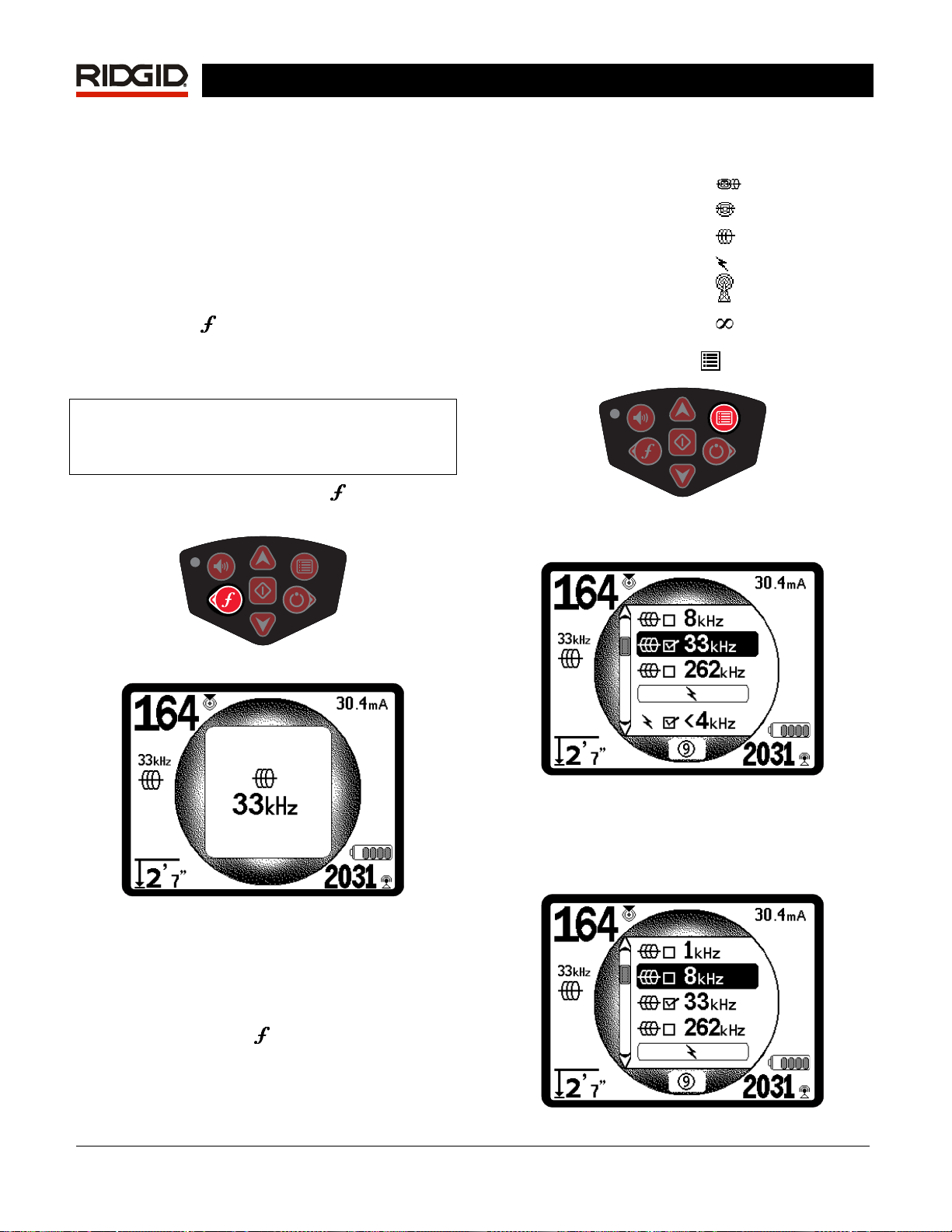
1. Push the Menu Key
Figure 13: Menu Key
The Main Menu screen is then activated:
Figure 14). Frequencies are
(if active)
:
Figure 11: Frequency Key
Figure 12: Line Trace Frequency Selected with
Frequency Key
Activating Frequencies
Frequencies can be chosen for the set of CheckedActive frequencies so they will become available
using the Frequency Key
deactivated to keep the frequency set smaller.
. Frequencies can also be
Figure 14: Main Menu
2. Using the Up and Down Keys, highlight
the frequency desired (
example, the operator is activating the 8 kHz
frequency.
Figure 15). In this
Ridge Tool Company Elyria, Ohio U.S.A www.seektech.com 11
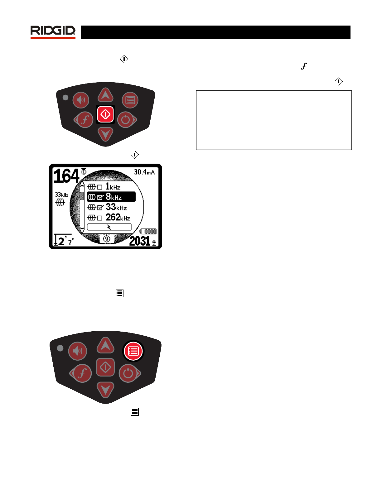
Figure 15: Highlighting a Desired Frequency (8 kHz)
3. Press the Select Key
check the box for each frequency to be used.
SeekTech SR-60
(shown below) to
for activation, see “Frequency Selection Control” on
33.
page
A long press on the Frequency Key
list of all Checked Active Frequencies. To use one,
simply scroll down to it and press the Select Key
Note on 93 kHz Frequency Use
The SR-60 offers two 93 kHz frequencies for Line
Tracing. The default 93 kHz frequency has an actual
cycle count of 93,623 cycles per second.
But some older transmitters use a different value for
the nominal 93 kHz frequency, 93,696 cycles per
second. This is found in the SR-60 listed as “93k-B”.
will bring up a
.
Figure 16: Select Key
Figure 17: Desired Frequency Checked
Frequencies that have been selected for use will
show a check in the box next to them.
4. Press the Menu Key
choice and exit. Letting the unit countdown
and exit automatically will have the same
effect.
again to accept the
If you find that your transmitter signal at 93 kHz
cannot be detected by the SR-60, set the locator’s
frequency to 93-B kHz, which is set to the older
value. Both 93 and 93-B frequencies can be found
under the Line Trace category of the Frequency
Selection sub-menu.
Sounds of the SR-60
The sound level is driven by the proximity to the
target. The closer to the target, the higher the sound
pitch will be. A rising tone indicates increasing signal.
In Active Line Trace or Passive Line Trace mode,
sound is on one continuous curve and does not rescale.
In Line Tracing modes, the default distortion
response also activates an audio signal proportionate
to the distortion in the detected field. When there is
no distortion present, the sound of the SR-60 is a
clear warbling sound when on the left side of the
detected field, with a slight click added when on the
right side of the detected field. If distortion is detected
a sound similar to AM radio static sound can be
heard, which gets stronger as the degree of distortion
increases, similar to the unfocusing that signals
distortion visually around the Tracing Line. If the
distortion response feature is disabled, the static
sound does not occur.
In Sonde Mode, if the sound level reaches its highest
point, it will “re-scale” to a medium level and continue
signaling from the new starting point.
In Sonde Mode, the pitch will “ratchet” upward. That
Figure 18: Menu Key
The Main Menu lists all frequencies available for
activation. For information on adding additional
frequencies to the Main Menu so they can be chosen
is, it will rise and then re-scale (fall) in pitch while
approaching the Sonde. Moving away from the
Sonde, it will drop to a lower pitch and remain there
as long as one moves away from the Sonde. Moving
back toward the Sonde again it will resume rising in
steps starting from the level it had reached
previously. This serves as an indication when the
12 www.seektech.com Ridge Tool Company Elyria, Ohio U.S.A

SeekTech SR-60
locator receiver is getting closer or further away from
the Sonde.
If desired, force the sound to re-center at a medium
level (in any mode) by pressing the Select Key during
operation. See also the “Directional Sound” section,
below.
Key Items in Using the SR-60
PROXIMITY SIGNAL reflects the proximity of the
locator to the target utility; the closer the locator
moves to the center of the detected field, the higher
the Proximity Signal number gets. The Proximity
Signal is calculated from the ratio of the signals
received at the lower and upper antennas, adjusted
for scalability.
SIGNAL STRENGTH represents the strength of the
field being detected by the lower antenna node of the
SR-60, converted mathematically for scalability. In a
clear and undistorted field, you can locate based on
Signal Strength alone.
DISTORTION is the degree to which the field
detected is deformed. In an undistorted environment,
current on a long conductor produces a field which is
cylindrical, down the conductor. If multiple fields are
present, the detected field is pushed or pulled out of
shape and the different antennas will pick up different
field strengths. On the SR-60, distortion is reflected
by the Tracing Line growing unfocused instead of
sharp, or by disagreement among the Guidance
Arrows, Tracing Line, and Signal Strength.
TRACING LINE indicates the direction and degree of
distortion in the detected field.
GUIDANCE ARROWS are driven by the signals
received at the guidance antennas of the SR-60.
When the fields detected by these side antennas are
equal, the arrows will center. If one is receiving a
stronger field signal than the other, the arrows will
point toward the probable center of the target
conductor. Moving in the direction indicated by the
arrows will bring you closer to the center of the
detected field. A small “guidance line” at the end of a
guidance arrow indicates the degree of alignment
with the conductor’s field. It will be at its maximum
length when correctly aligned with the conductor, with
the guidance antenna axis crossing the field at 90°.
Rotational guidance arrows on the perimeter of the
screen will indicate the direction you need to turn to
align with the detected conductor.
DIRECTIONAL SOUND from stereo speakers will let
you follow a line by sound, while staying visually alert
for nearby traffic or obstacles. The Sound Pointer
speakers are designed to be clipped to a jacket or
vest on either shoulder. Stereo sound from the
speakers will fade to the left or right. The louder side
indicates the direction toward the center of the
detected field. Sound will balance when over the
center of the line. The operator can stay centered on
the line using sound signals instead of the visual
cues on the screen. The SR-60 comes with clip-on
speakers designed to be attached to the left and right
shoulders of a safety vest for this purpose.
Shutting Down
Pressing the Power Key at any time during operation
will start a count-down of 3 seconds, during which the
shut-down tone will sound. At the end of the countdown, the SR-60 will shut down.
Figure 19: Count-Down Screen (Shutting Down)
Line Tracing with the SR-60
There are two major ways to look for lines
underground with the SR-60. They are called Active
and Passive. The difference is that in Active Line
Tracing, a current is placed on a conductor using a
transmitter, and that specific signal is then sought for
using the locator. Passive tracing does not use a
transmitter and seeks for any signal that may be
picked up at particular frequencies.
Active Line Tracing
In active line tracing, underground lines are
energized with a Line Transmitter. This active signal
is then traced using the SR-60. A Line Transmitter is
different from a Sonde in that it is used to energize a
conducting target line, rather than acting as a target
for a locate itself, the way a Sonde does. Line
transmitters energize lines by direct connection
clips, or by directly inducing the signal using a clamp
or by inducing the signal using inductive coils
into the transmitter.
Direct Connect Mode: The transmitter is attached
by direct metal-to-metal connection to the target
conductor at some access point such as a valve, a
with
,
built
Ridge Tool Company Elyria, Ohio U.S.A www.seektech.com 13
meter, or other point. Important: The connection
between the transmitter and the conductor must be a
clean, firm connection. The transmitter is also
connected to a ground stake providing a strong open
path to ground. Important: A weak ground
connection is the most frequent cause of a poor
tracing circuit. Make sure the transmitter is well
connected to ground, and has enough exposure to
the ground to allow current to flow through the circuit.
Inductive Clamp Mode: The transmitter is
connected to an inductive clamp which is then closed
around a pipe or cable. The transmitter energizes the
clamp, which then induces a current in the conductor.
Important: Make sure the SR-60 is set to trace mode
and set to the same frequency as the transmitter. Do
not clamp onto a live conductor. This mode works
best when both ends of the conductor are grounded.
Inductive Mode: The transmitter is placed over
conductor. There is no direct connection; the internal
coils of the transmitter generate a strong field through
the ground which induces a current in the
underground conductor of interest. Important: If the
transmitter is too close to the SR-60 in this mode, it
can cause “air-coupling” which means the locator is
reading more on the signal from the transmitter’s
field, than on the target conductor. (See page 16).
Note: When using Inductive Mode, it is always
possible to move the transmitter to a different point
along the target line. This will sometimes improve the
circuit and provide a better signal.
SeekTech SR-60
the
Figure 20: Line Trace Frequency Chosen with the
Frequency Key (This screen will flash briefly when a
new frequency is chosen.)
2. Observe the Proximity Signal to ensure that
the receiver is picking up the transmitted
signal. The Proximity Signal should peak over
the line and drop off on either side.
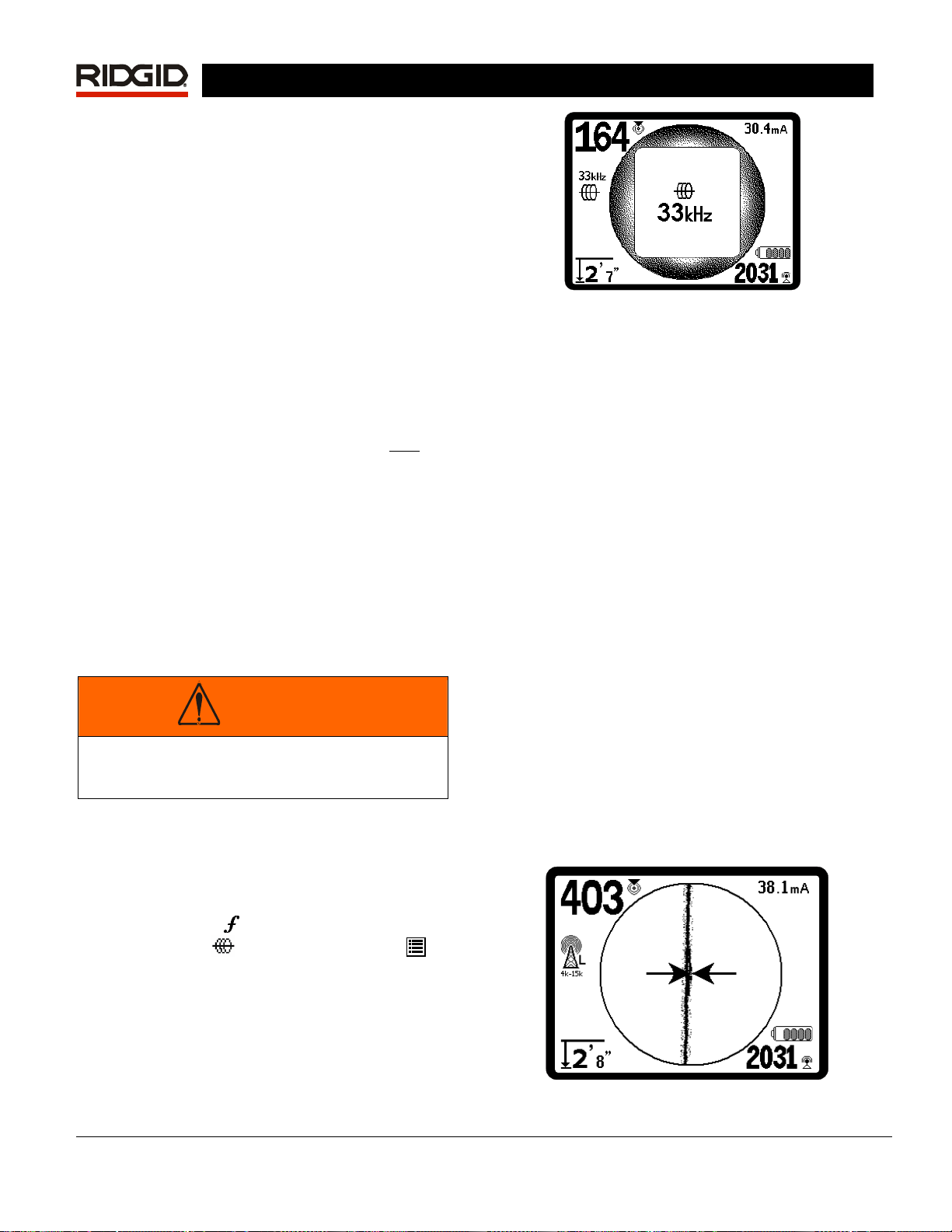
When tracing, the direction of the detected
field will be shown on the screen by the
Tracing Line. The Tracing Line will be a clear,
single line if the field being detected is
undistorted.
If other fields are interfering in some way, the
distortion caused by those fields will be
reflected by a blurring of the Tracing Line.
The more distorted the detected field, the broader
the cloud around the Tracing Line will be. This
alerts the operator that the apparent axis of the
line may be influenced by other fields, and
requires careful evaluation.
WARNING
Connect ground and power leads of the
transmitter before powering the transmitter on,
to avoid electric shock. See warning on page 4.
1. Energize the target conductor according to
the transmitter manufacturer’s instructions,
using one of the methods described above.
Select the transmitter frequency. Set the
frequency on the SR-60 to the same
frequency used on the transmitter, using the
Frequency Key
line trace icon
return to the operating screen. To activate
frequencies not yet made active, see “Frequency
Selection Control” on page
. Be sure the frequency has a
. Push the Menu Key to
33.
The Tracing Line has three important functions.
It represents the location, and the direction, of the
signal being traced. It reflects changes in
direction of the target utility — when the utility
makes a turn, for example. And it helps recognize
signal distortion. It does this by becoming
cloudier as distortion increases. Disagreement
between different indicators can also indicate
distortion.
Figure 21: Tracing Line Showing Low Distortion
14 www.seektech.com Ridge Tool Company Elyria, Ohio U.S.A
 Loading...