


.SP6498 Belt Drive Saw 05/03 7/15/03 7:04 AM Page 1
TS3650
OPERATORS MANUAL
10" CAST IRON TABLE SAW
1-866-539-1710
! WARNING:
For Your Own Safety Read
Operator’s Manual Before
Operating Saw.
Part No. SP6498 |
Printed in Taiwan |
.SP6498 Belt Drive Saw 05/03 7/15/03 7:04 AM Page 2
Table of Contents |
|
Section |
Page |
Table of Contents .............................................. |
2 |
Safety Instructions For Table Saw .................... |
3 |
Safety Signal Words ...................................... |
3 |
Before Using The Saw .................................. |
3 |
When Installing Or Moving The Saw ................ |
4 |
Before Each Use ........................................... |
4 |
To Reduce the Risk of Injury From |
|
Jams, Slips Or Thrown Pieces |
|
(Kickbacks Or Throwbacks) .......................... |
5 |
Plan Ahead To Protect Your |
|
Eyes, Hands, Face and Ears ........................ |
6 |
Whenever Sawblade Is Spinning .................. |
7 |
Additional Safety Instructions For: ................ |
8 |
Additional Safety Instructions For: ................ |
9 |
Additional Safety Instructions For |
|
Herc-U-Lift™ Caster System: ........................ |
9 |
Glossary of Terms for Woodworking ................ |
9 |
Motor Specifications and Electrical |
|
Requirements ............................................... |
11 |
Power Supply and Motor Specifications |
.....11 |
General Electrical Connections ................... |
11 |
Changing Motor Voltage .............................. |
13 |
Motor Thermal Overload Protector ............. |
14 |
Wire Sizes .................................................... |
14 |
Unpacking and Checking Contents ................ |
15 |
Tools Needed ............................................... |
15 |
Unpacking .................................................... |
15 |
List of Loose Parts ....................................... |
16 |
Herc-U-Lift™ Caster Carton ........................ |
17 |
Loose Parts ................................................. |
17 |
Assembly ......................................................... |
17 |
Installing Bevel Handwheel ......................... |
17 |
Installing Elevation Handwheel ................... |
18 |
Assembling Leg Stand ................................ |
18 |
Mounting Your Saw ..................................... |
19 |
Assembling Table Extensions ...................... |
21 |
Checking Table Insert .................................. |
22 |
Checking Heeling Adjustment or Parallelism |
|
of Sawblade to Miter Gauge Groove .......... |
23 |
Checking Blade Tilt, or Squareness |
|
of Blade to Table .......................................... |
25 |
Checking Tilt Mechanism ............................ |
26 |
Assembling Herc-U-Lift™ Caster System ... |
27 |
Assembly Tips .............................................. |
27 |
Upper Assembly .......................................... |
27 |
Lower Assembly .......................................... |
28 |
Assembling Herc-U-Lift™ Caster System |
|
to Saw .......................................................... |
29 |
Installation Instructions ................................ |
29 |
Operation of Herc-U-Lift™ Caster System .30 |
|
Installing Front Rip Fence Guide Bar ......... |
31 |
Installing Rear Fence Guide Bar ................. |
32 |
Adjusting Rip Fence Guide Bars ................. |
33 |
Installing Spacer Bar ................................... |
34 |
Rip Fence Alignment Adjustment ................ |
35 |
Rip Fence Lock Lever Adjustment .............. |
35 |
Adjusting Fence Indicator ............................ |
36 |
Installing Blade Guard ................................. |
36 |
Aligning Blade Guard ................................... |
37 |
Section |
Page |
|
Mounting the Motor ..................................... |
|
38 |
Installing Belt ............................................... |
|
39 |
Installing Belt Guard .................................... |
|
39 |
Mounting Switch and End Caps .................. |
40 |
|
Securing Electrical Cords ............................ |
41 |
|
Installing Guide Bar End Caps .................... |
41 |
|
Getting to Know Your Table Saw .................... |
42 |
|
Additional Safety Instructions When |
|
|
Using Zero Clearance Insert ....................... |
46 |
|
Remove the Existing |
Insert. ....................... |
47 |
Installing Zero Clearance Insert/Sawblade. 47 |
||
Installing Zero Clearance Insert/Dado Blades .. |
48 |
|
Operation Tips ............................................. |
|
48 |
Safety Instructions for Basic Saw Operations ...... |
49 |
|
Before Each Use ......................................... |
|
49 |
To Reduce the Risk of Injury From Jams, |
|
|
Slips Or Thrown Pieces (Kickbacks Or |
|
|
Throwbacks) ................................................ |
|
49 |
Plan Ahead To Protect Your Eyes, |
|
|
Hands, Face and Ears ................................ |
51 |
|
Whenever Sawblade Is Spinning ................ |
52 |
|
Work Feed Devices ........................................ |
|
52 |
Attaching Wood Face Board ....................... |
53 |
|
Push Block ................................................... |
|
54 |
Auxiliary Fence ............................................ |
|
55 |
Work Support for Material over 26" Wide ... |
56 |
|
Basic Saw Operations .................................... |
|
57 |
Using the Miter Gauge ................................ |
57 |
|
Additional Safety Instructions |
|
|
for Crosscutting ........................................... |
|
57 |
Crosscutting ................................................. |
|
57 |
Repetitive Crosscutting ............................... |
58 |
|
Miter Crosscutting ........................................ |
|
59 |
Bevel Crosscutting ....................................... |
|
59 |
Compound Crosscutting .............................. |
59 |
|
Using the Rip Fence .................................... |
|
60 |
Additional Safety Instructions for Rip Cuts |
.60 |
|
Ripping ......................................................... |
|
61 |
Bevel Ripping Narrow Work ........................ |
62 |
|
Using Featherboards for Thru-Sawing ........ |
63 |
|
Using Featherboards for Non Thru-Sawing ..... |
63 |
|
Resawing ..................................................... |
|
64 |
Using Carbide Tipped Blades ..................... |
65 |
|
Dadoing ....................................................... |
|
65 |
Rabbeting .................................................... |
|
66 |
Ploughing and Molding ................................ |
66 |
|
Molding ........................................................ |
|
67 |
Adjustments .................................................... |
|
68 |
Miter Gauge ................................................. |
|
68 |
Maintaining Your Table Saw ........................... |
69 |
|
Maintenance ................................................ |
|
69 |
Lubrication ................................................... |
|
70 |
RIDGID Recommends the Following |
|
|
Accessories .................................................. |
|
70 |
Wiring Diagrams .............................................. |
|
71 |
Troubleshooting .............................................. |
|
72 |
General ........................................................ |
|
72 |
Motor ............................................................ |
|
73 |
Notes ............................................................... |
|
75 |
Repair Parts .................................................... |
|
76 |
2

.SP6498 Belt Drive Saw 05/03 7/15/03 7:04 AM Page 3
Safety Instructions For Table Saw
Safety is a combination of common sense, staying alert and knowing how your table saw works. Read this manual to understand this table saw.
Safety Signal Words
DANGER: means if the safety information is not followed someone will be seriously injured or killed.
WARNING: means if the safety information is not followed someone could be seriously injured or killed.
CAUTION: means if the safety information is not followed someone may be injured.
Before Using The Saw
WARNING: Some dust created by power sanding, sawing, grinding, drilling, and other construction activities contains chemicals known (to the State of California) to cause cancer, birth defects or other reproductive harm. Some examples of these chemicals are:
Lead from lead-bases paints
•Crystalline silica from bricks and cement and other masonry products, and
•Arsenic and chromium from chemically-treated lumber.
Your risk from these exposures varies, depending on how often you do this type of work. To reduce your exposure to these chemicals: work in a well ventilated area, and work with approved safety equipment, such as those dust masks that are specially designed to filter out microscopic particles.
WARNING: To reduce the risk of mistakes that could cause serious, permanent injury, do not plug the table saw in until the following steps have been satisfactorily completed.
•Completely assemble and align saw (See “Assembly” section).
•Learn the use and function of the ON-OFF switch, blade guard, spreader, anti-kickback device, miter gauge, rip fence, table insert, blade elevation and blade tilt controls (See “Getting to Know Your Table Saw” section).
•Review and understand all safety instructions and operating procedures in this manual.
•Review the maintenance methods for this saw (See “Maintaining Your Table Saw” section).
3
.SP6498 Belt Drive Saw 05/03 7/15/03 7:04 AM Page 4
Safety Instructions For Table Saw (continued)
• Find and read all the warning labels found on the saw (shown below).
When Installing Or Moving The Saw
Reduce the Risk of Dangerous
Environment.
•Use the saw in a dry, indoor place protected from rain.
•Keep work area well lighted.
•Use recommended accessories. Consult the owner’s manual for recommended accessories. The use of improper accessories may cause risk of injury to persons.
To reduce the risk of injury from unexpected saw movement.
•Bolt or clamp the saw to firm level surface where there is plenty of room to handle and properly support the workpiece (See “Assembly-Mounting Your Saw” section).
•Support the saw so the table is level and the saw does not rock.
•When using a table extension longer than 12" attached to any side of the saw, bolt the saw to a stationary surface or prop up the outer end of the extension from the floor or bench top to keep the saw from tipping.
•Put the saw where neither operator nor bystanders must stand in line with the sawblade.
•To reduce the risk of injury from electrical shock, make sure your fingers do not touch the plug’s metal prongs when plugging in or unplugging the saw.
•Never Stand On Tool. Serious injury could occur if the tool tips or you accidentally hit the cutting tool. Do not store anything above or near the tool where anyone might stand on the tool to reach them.
Before Each Use
Inspect your saw.
•To reduce the risk of injury from accidental starting, turn the switch off, unplug the saw, and remove the switch key before raising or removing
the guard, changing the cutting tool, changing the setup, or adjusting anything. Make sure switch is in OFF position before plugging in.
4

.SP6498 Belt Drive Saw 05/03 7/15/03 7:04 AM Page 5
•Check for alignment of moving parts, binding of moving parts, breakage of parts, saw stability, and any other conditions that may affect the way the saw works.
•If any part is missing, bent or broken in any way, or any electrical part does not work properly, turn the saw off and unplug the saw.
•Replace damaged or missing parts before using the saw again.
•Use the sawblade guard, spreader and anti-kickback pawls for any thrusawing (whenever the blade comes
through the top of the work-piece). Make sure the anti-kickback pawls work properly. Make sure the spreader is in line with sawblade (See “Assembly-Aligning Blade Guard” section).
•Remove adjusting keys and wrenches. Form a habit of checking for and removing keys and adjusting wrenches from table top before turning saw on.
•Make sure all clamps and locks are tight and no parts have excessive play.
To Reduce the Risk of Injury From Jams, Slips Or Thrown Pieces (Kickbacks Or Throwbacks)
Inspect Your Blade.
•Choose the right blade or cutting accessory for the material and the type of cutting you plan to do.
•Use The Right Tool. Don’t force tool or attachment to do a job it was not designed for.
•Never use grinding wheels, abrasive cutoff wheels, friction wheels (metal cutting blades) wire wheels or buffing wheels. They can fly apart explosively.
•Cut only wood, wood like or plastic materials. Do not cut metal.
•Choose and inspect your cutting tool carefully:
•To reduce the risk of cutting tool failure and thrown shrapnel (broken pieces of blade), use only 10” or smaller blades or other cutting tools marked for speeds of 5000 rpm or higher.
•Always use unbroken, balanced blades designed to fit this saw’s 5/8 inch arbor.
•When thru-sawing (making cuts where the blade comes through the workpiece top), always use a 10 inch diameter blade. This keeps the spreader closest to the blade.
•Do not over tighten arbor nut. Use arbor wrenches to tighten it securely.
•Use only sharp blades with properly set teeth. Consult a professional blade sharpener when in doubt.
•Keep blades clean of gum and resin.
•Never use the saw without the proper table insert.
•Inspect your work area
•Keep work area clean.
•Cluttered areas and benches invite accidents. Floor must not be slippery from wax or sawdust.
•To reduce the risk of burns or other fire damage, never use the saw near flammable liquids, vapors or gases.
•To reduce the risk of injury, don’t do layout, assembly, or setup work on the table while blade is spinning. It could cut or throw anything hitting the blade.
5
.SP6498 Belt Drive Saw 05/03 7/15/03 7:04 AM Page 6
Safety Instructions For Table Saw (continued)
Plan your work
•Use the right tool. Don’t force tool or attachment to do a job it was not designed for.
Inspect your workpiece.
•Make sure there are no nails or foreign objects in the part of the workpiece to be cut.
•When cutting irregularly shaped workpieces, plan your work so it will not slip and pinch the blade:
•A piece of molding for example, must lie flat or be held by a fixture or jig that will not let it twist, rock or slip while being cut. Use jigs or fixtures where needed to prevent workpiece from shifting.
•Use a different, better suited type of tool for work that can’t be made stable.
Plan your cut
•To reduce the risk of kickbacks and throwbacks - when a part or all of the workpiece binds on the blade and is thrown violently back toward the front of the saw:
•Never cut Freehand. Always use either a rip fence, miter gauge or fixture to position and guide the work, so it won’t twist or bind on the blade and kick back.
•Make sure there’s no debris between the workpiece and its supports.
•Use extra caution with large, very small or awkward workpieces.
•Use extra supports (tables, saw horses, blocks, etc.) for any workpieces large enough to tip when not held down to the table top. Never use another person as a substitute for a table extension, or as additional support for a workpiece that is longer or wider than the basic saw table, or to help feed, support or pull the workpiece.
•Never confine the piece being cut off, that is, the piece not against the rip fence, miter gauge or fixture. Never hold it, clamp it, touch it, or use length stops against it. It must be free to move. If confined, it could get wedged against the blade and cause a kickback or throwback.
•Never cut more than one workpiece at a time.
•Never turn your table saw “ON” before clearing everything except the workpiece and related support devices off the table.
Plan Ahead To Protect Your Eyes, Hands, Face and Ears
Dress for safety
•Do not wear loose clothing, gloves, neckties or jewelry (rings, wrist watches). They can get caught and draw you into moving parts.
•Wear nonslip footwear.
•Tie back long hair.
•Roll long sleeves above the elbow.
•Noise levels vary widely. To reduce the risk of possible hearing damage,
wear ear plugs or muffs when using table saw for hours at a time.
•Any power saw can throw foreign objects into the eyes. This can result in permanent eye damage. Always wear safety goggles, not glasses complying with ANSI Z87.1 (or in Canada CSA Z94.3-99) shown on package. Everyday eyeglasses have only impact resistant lenses. They are not safety
6
.SP6498 Belt Drive Saw 05/03 7/15/03 7:04 AM Page 7
glasses. Safety goggles are available at many local retail stores. Glasses or goggles not in compliance with ANSI or CSA could seriously hurt you when they break.
WEAR YOUR
FORESIGHT IS
BETTER THAN
NO SIGHT
•For dusty operations, wear a dust mask along with safety goggles.
Plan the way you will push the workpiece through.
•Never pull the workpiece through.
Start and finish the cut from the front of the table saw.
•Never put your fingers or hands in the path of the sawblade or other cutting tool.
•Never reach in back of the cutting tool with either hand to hold down workpiece, support the workpiece, remove wood scraps, or for any other reason.
•To reduce the risk of hand positions where a sudden slip could cause fingers or hand to move into a sawblade or other cutting tool.
•Don’t overreach. Always keep good footing and balance.
•Push the workpiece against the rotation of the blade, never feed material into the cutting tool from the rear of the saw.
•Always push the workpiece all the way past the sawblade.
•As much as possible, keep your face and body to one side of the sawblade, out of line with a possible kickback or throwback.
•Set the cutting tool as low as possible for the cut you’re planning.
Reduce the Risk of Accidental
Starting
•Make sure switch is “OFF” before plugging saw into a power outlet.
Whenever Sawblade Is Spinning
WARNING: Don't allow familiarity (gained from frequent use of your table saw) to cause a careless mistake. Always remember that a careless fraction of a second is enough to cause a severe injury.
•Before actually cutting with the saw, watch it while it runs for a short while. If it makes an unfamiliar noise or vibrates a lot, stop immediately. Turn the saw off. Unplug the saw. Do not restart until finding and correcting the problem.
•Make sure the top of the arbor or cutting tool turns toward the front of the saw.
Keep Children Away.
• Keep all visitors a safe distance
from the table saw.
7
•Make sure bystanders are clear of the table saw and workpiece.
Don’t Force Tool.
•Let the blade reach full speed before cutting.
•It will do the job better and safer at its designed rate.
•Feed the workpiece into the saw only fast enough to let the blade cut without bogging down or binding.
Before freeing jammed material.
•Turn switch “OFF”.
•Wait for all moving parts to stop.
•Unplug the saw.
•Check blade, spreader and fence for proper alignment before starting again.
.SP6498 Belt Drive Saw 05/03 7/15/03 7:04 AM Page 8
Safety Instructions For Table Saw (continued)
•To reduce the risk of throwback of cut off pieces.
•Use the guard assembly.
To remove loose pieces beneath or trapped inside the guard.
•Turn saw “OFF”.
•Remove switch key.
•Wait for blade to stop before lifting the guard.
Before Leaving The Saw.
•Turn the saw off.
•Wait for blade to stop spinning.
•Unplug the saw.
•Make workshop child-proof. Lock the shop. Disconnect master switches. Remove the yellow switch key. Store it away from children and others not qualified to use the tool.
Additional Safety Instructions For:
Rip Type Cuts.
•Never use the miter gauge when ripping.
• |
Use a push stick whenever the |
|
|
|
|
||||||
Featherboard |
|
|
|
||||||||
|
fence is 2 inches or more from the |
See “Work Feed Devices” section for |
|
||||||||
|
blade. |
|
|
Material and Dimensions |
|
|
|
||||
|
|
|
|
|
|
|
|
|
|
||
|
|
|
Before Starting. |
|
|
|
|
|
|||
• When thru-sawing, use an auxiliary |
|
|
|
|
|
||||||
• To reduce the risk of kickbacks and |
|||||||||||
|
fence and push block whenever the |
||||||||||
|
slips into the blade, make sure the |
||||||||||
|
fence must be between 1/2 and 2 |
||||||||||
|
rip fence |
is |
parallel |
to |
the |
||||||
|
inches from the blade. |
|
|
||||||||
|
|
|
sawblade. |
|
|
|
|
|
|
||
• |
Never thru-saw rip cuts narrower |
|
|
|
|
|
|
||||
|
|
|
|
|
|
|
|||||
|
than 1/2 inch. (See |
“Basic Saw • Before thru-sawing, check the anti- |
|||||||||
|
Operations-Ripping |
and |
Bevel |
kickback pawls. The pawls |
must |
||||||
|
stop a kickback once it has started. |
||||||||||
|
Ripping” sections.) |
|
|
||||||||
|
|
|
Replace or |
sharpen |
anti-kickback |
||||||
• Never rip anything shorter than 10” |
|||||||||||
pawls when |
points |
become |
dull. |
||||||||
|
long. |
|
|
||||||||
|
|
|
(See “Maintaining Your Table Saw - |
||||||||
• |
When using a push stick or push |
||||||||||
Anti-Kickback Pawls” section.) |
|
|
|||||||||
|
block, the trailing end of the board |
|
|
||||||||
|
• Plastic and composition (like hard- |
||||||||||
|
must be square. A push stick or |
||||||||||
|
board) materials may be |
cut on |
|||||||||
|
block against an uneven end could |
||||||||||
|
your saw. However, since these are |
||||||||||
|
slip off or push the work away from |
||||||||||
|
usually quite hard and slippery, the |
||||||||||
|
the fence. |
|
|
||||||||
|
|
|
anti-kickback pawls may not stop a |
||||||||
• A Featherboard can help guide the |
|||||||||||
kick-back. Therefore, be especially |
|||||||||||
|
workpiece. (see ”Basic |
Saw |
|||||||||
|
careful in your |
setup and |
cutting |
||||||||
|
Operation-Using Featherboards for |
||||||||||
|
procedures. |
|
|
|
|
|
|
||||
|
Thru-Sawing.” section) |
|
|
|
|
|
|
|
|
||
|
|
|
While Thru-sawing. |
|
|
|
|
||||
• |
Always use featherboards for any |
|
|
|
|
||||||
• |
|
|
|
|
|
|
|||||
|
non thru rip type cuts. (See “Basic |
|
|
|
|
|
|
||||
Saw Operations - Using Featherboards for Non-Thru Sawing” section).
8
.SP6498 Belt Drive Saw 05/03 7/15/03 7:04 AM Page 9
Additional Safety Instructions For:
Crosscut Type Cuts.
•Never use the rip fence when cross-cutting.
•An auxiliary wood facing attached to the miter gauge can help prevent workpiece twisting and throwbacks. Attach it to the slots provided. Make the facing long enough and big enough to support your work. Make sure, however, it will not interfere with the sawblade guard.
Before Starting
•Use jigs or fixtures to help hold any piece too small to extend across the full length of the miter gauge face during the cut. This lets you properly hold the miter gauge and workpiece and helps keep your hands away from the blade.
While Cutting
•To reduce the risk of blade contact, always hold the miter gauge as shown in “Basic Saw Operations - Using The Miter Gauge”.
Additional Safety Instructions For Herc-U-Lift™ Caster System:
Before Using the Caster System
Read the following warning located on the plate assembly:
To reduce the risk of injury from |
• the tool on a firm level surface |
unexpected tool movement. |
where there is plenty of room to |
• Check to make sure tool does not |
handle and properly support the |
move prior to use. If tool moves, |
workpiece. |
adjust all four leveler feet to support |
|
the tool. |
|
Glossary of Terms for Woodworking
Anti-Kickback Pawls
Device which, when properly maintained, is designed to stop the workpiece from being thrown towards the front of the saw at the operator during ripping operation.
Arbor
The shaft on which a cutting tool is mounted.
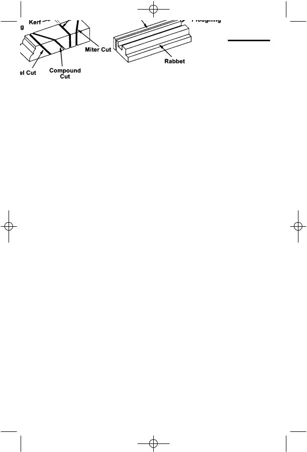
Bevel Cut
An angle cutting operation made through the face of the workpiece.
Compound Cut
A simultaneous bevel and miter crosscutting operation.
Crosscut
A cutting operation made across the width of the workpiece.
9
.SP6498 Belt Drive Saw 05/03 7/15/03 7:04 AM Page 10
Glossary of Terms for Woodworking (continued)
Dado
A non thru cut which produces a square sided notch or trough in the workpiece.
Featherboard
A device which can help guide workpieces during rip type operation.
Freehand
Performing a cut without the use of fence (guide), miter gauge, fixture, hold down or other proper device to prevent the work-piece from twisting during the cutting operation. Twisting of the workpiece can cause it to be thrown.
Gum
A sticky, sap based residue from wood products.
Heel
Misalignment of the sawblade such that the blade is not parallel to the miter gauge groove.
Kerf
The amount of material removed by the blade in a through cut or the slot produced by the blade in a nonthrough or partial cut.
Kickback
An uncontrolled grabbing and throwing of the workpiece back toward the front of the saw.
Leading End
The end of the workpiece which, during a rip type operation, is pushed into the cutting tool first.
Miter Cut
An angle cutting operation made across the width of the workpiece.
Molding
A non through cut which produces a special shape in the workpiece used for joining or decoration.
Ploughing
Grooving with the grain the length of the workpiece, using the fence. (A type of non-through cut.)
Push Stick
A device used to feed the workpiece through the saw during narrow ripping type operations which helps keep the OPERATORS hands well away from the blade.
Push Block
A device used for ripping type operations too narrow to allow use of a push stick.
Rabbet
A notch in the edge of a workpiece. (A type of non-through cut).
Resin
A sticky, sap based substance that has hardened.
Revolutions Per Minute (RPM)
The number of turns completed by a spinning object in one minute.
Rip Cut
A cutting operation along the length of the workpiece.
10
.SP6498 Belt Drive Saw 05/03 7/15/03 7:04 AM Page 11
Sawblade Path
The area of the workpiece or table top directly in line with either the travel of the blade or the part of the workpiece which will be, or has been, cut by the blade.
Set
The distance that the tip of the sawblade tooth is bent (or set) outward from the face of the blade.
Throw-Back
Throwing of pieces in a manner similar to a kickback.
Thru-Sawing
Any cutting operation where the blade extends completely through the thickness of the workpiece.
Trailing End
The workpiece end last cut by the blade in a ripping operation.
Workpiece
The item on which the cutting operation is being performed. The surfaces of a work-piece are commonly referred to as faces, ends, and edges.
Motor Specifications and Electrical Requirements
Power Supply and Motor
Specifications
WARNING: To reduce the risk of electrical hazards, fire hazards or damage to the tool, use proper circuit protection. Your tool is wired at the factory for operation using the voltage shown. Connect tool to a power line with the appropriate voltage and a 15-amp branch circuit. Use a 15-amp time delay type fuse or circuit breaker. To reduce the risk of shock or fire, if power cord is worn or cut, or damaged in any way, have it replaced immediately.
The A-C motor used on this tool is a totally enclosed fan cooled (TEFC) capacitor start, capacitor run non-reversible type, having the following specifications. It is wired at the factory for operation on 110-120v AC, 60 Hz. service.
13 6.5
General Electrical Connections
WARNING: To reduce the risk of electrocution:
1.Use only identical replacement parts when servicing. Servicing should be performed by a qualified service technician.
2.Do not use in rain or where floor is wet.
This tool is intended for indoor residential use only.
WARNING: Do not permit fingers to touch the terminals of plug when installing or removing the plug to or from the outlet.
11
.SP6498 Belt Drive Saw 05/03 7/15/03 7:04 AM Page 12
Motor Specifications and Electrical Requirements (continued)
110-120 Volt, 60 Hz. Tool Information
The plug supplied on your tool may not fit into the outlet you are planning to use. Your local electrical code may require slightly different power cord plug connections. If these differences exist refer to and make the proper adjustments per your local code before your tool is plugged in and turned on.
In the event of a malfunction or breakdown, grounding provides a path of least resistance for electric current to reduce the risk of electric shock. This tool is equipped with an electric cord having an equipment-grounding conductor and a grounding plug, as shown. The plug must be plugged into a matching outlet that is properly installed and grounded in accordance with all local codes and ordinances.
Do not modify the plug provided. If it will not fit the outlet, have the proper outlet installed by a qualified electrician.
Improper connection of the equipmentgrounding conductor can result in a risk of electric shock. The conductor with insulation having an outer surface that is green with or without yellow stripes is the equipment-grounding conductor. If repair or replacement of the electric cord or plug is necessary, do not connect the equipment-grounding conductor to a live terminal.
If the grounding instructions are not completely understood, or if you are in doubt as to whether the tool is properly grounded check with a qualified electrician or service personnel.
WARNING: If not properly grounded, this tool can cause an electrical shock, particularly when used in damp locations, in proximity to plumbing, or out of doors. If an electrical shock occurs there is the potential of a secondary hazard, such as your hands contacting the sawblade.
12

.SP6498 Belt Drive Saw 05/03 7/15/03 7:04 AM Page 13
Changing Motor Voltage
WARNING: Electric shock can kill. To reduce the risk of shock, never connect plug to power source outlet until all assembly steps are completed. Unplug saw before making or changing any connections.
NOTE: The saw is prewired at the factory for 120V operation. Use the following procedure to change motor voltage from 120V to 240V.
1.Unplug the saw.
2.Open the motor junction box cover located on the side of the motor.
3.Remove and discard the electrical tape from the wire connectors. Remove wire connectors.
4.Reconnect the leads as shown in the “Wiring Diagram” section on page 71 of this manual.
5.Reinstall the wire connectors and wrap with two layers of new U.L. listed electrical tape per wire connector.
6.Recheck your wiring to the wiring diagrams. Do this so you can be sure that the wiring is correct.
7.Reinstall the junction box cover.
8.Cut off the 120 volt power cord plug and replace it with a (3 blade) 240 volt, 15 amp U.L. listed plug. (See illustration of 240V plug & receptacle.) Connect the power cord white and black leads, respectively, to the “hot” plug blade terminals and connect the power cord green grounding wire to the plug ground prong terminal.
9.Plug your saw into a 220-240V, 15 amp, 3 blade receptacle.
10.Make certain the receptacle is connected to a 240V A.C. power supply through a 240V branch circuit having at least a 15 amp capacity and protected by a 15 amp time-delay fuse of circuit breaker.
Junction
Box Cover
13
.SP6498 Belt Drive Saw 05/03 7/15/03 7:04 AM Page 14
Motor Specifications and Electrical Requirements (continued)
Motor Thermal Overload Protector
CAUTION: To reduce the risk of motor damage, this motor should be blown out or vacuumed frequently to prevent sawdust buildup which will interfere with normal motor ventilation.
Your saw is equipped with a manual-reset thermal-overload protector designed to open the power line circuit when the motor temperature exceeds a safe level, when motor is overloaded or when a low voltage condition exists.
WARNING: To reduce the risk of thrown objects or blade contact from unexpected starting. If the protector stops the saw motor, immediately turn the saw switch “OFF”, remove the key and allow motor time to cool.
1.After cooling to a safe operating temperature, the overload protector can be reset by pushing the red button on the junction box of the motor. If the red button will not click into place immediately, the motor is still too hot and must be allowed to cool for a while longer.
The time required for the motor to cool may be equal to the length of time the saw was used before the thermal overload protector opened. NOTE: An audible click will indicate the protector is reset, push hard to hear the click.
2.As soon as the red button is reset, the saw may be started and operated normally.
3.Frequent “blowing” of fuses or tripping of circuit breakers may result if:
a.Motor is overloaded - Overloading can occur if you feed too rapidly or if saw is misaligned.
b.Motor circuit is fused differently from recommendations - Always follow instructions for the proper fuse/ breaker. Do not use a fuse/breaker of greater capacity without consulting a qualified electrician.
Manual Reset
Button
c.Low voltage - Although the motor is designed for operation on the voltage and frequency specified on motor nameplate, normal loads will be handled safely on voltage not more than 10% above or below the nameplate voltage. Heavy loads, however, require that voltage at motor terminals equals the voltage specified on nameplate.
4.Most motor troubles may be traced to loose or incorrect connections, overloading, reduced input voltage (such as small size wire in the supply circuit) or to overly long supply circuit wire. Always check the connections, the load and the supply circuit whenever motor fails to perform satisfactorily. Check wire sizes and length with the Wire Size Chart below.
Wire Sizes
NOTE: Make sure the proper extension cord is used and is in good condition. The use of any extension cord will cause some loss of power. To keep this to a minimum and to prevent overheating and motor burn-out, use the table shown to determine the minimum wire size (A.W.G.) extension cord.
Use only 3-wire extension cords which have 3-prong grounding type plugs and 3-prong receptacles which accept the tool’s plug.
14 |
16 |
12 |
14 |
14
.SP6498 Belt Drive Saw 05/03 7/15/03 7:04 AM Page 15
Unpacking and Checking Contents
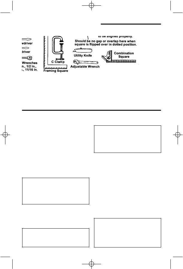
Tools Needed
10mm, 11mm, 12mm, 14mm, 17mm, 1/2 in., 11/16 in.
Unpacking
The TS3650 comes with two cartons labeld 1 of 2 and 2 of 2. Make sure you have both cartons before beginning assembly.
1.Separate saw and all parts from packing materials and check each one with the illustration and the “List of Loose Parts” to make certain all items are accounted for, before discarding any packing material. Call 1-866-539-1710 or E-mail us at info@ridgidwoodworking.com if any parts are damaged or missing.
WARNING: If any parts are missing, do not attempt to assemble the table saw, plug in the power cord or turn the switch on until the missing parts are obtained and are installed correctly.
2.Remove the protective oil that is applied to the table top and edges of the table and table extensions. Use any ordinary household type grease and spot remover.
WARNING: To reduce the risk of fire or health hazard, never use gasoline, naphtha, or similar highly volatile solvents.
3.Apply coat of paste wax to the table and table extensions.
WARNING: The saw is heavy. To reduce the risk of back injury, get help to lift the saw. Hold the saw close to your body. Bend your knees so you can lift with your legs, not your back.
NOTE: Before beginning assembly:
•Check that all parts are included. If you are missing any part, do not assemble the saw.
•Sometimes small parts can get lost in packaging material. Do not throw away any packaging until saw is put together. Check packaging for missing parts before contacting RIDGID.
•A complete parts list (Repair Parts) is at the end of the manual. Use this list to identify the part number of the missing part.
WARNING: For your own safety, never connect plug to power source outlet until all assembly steps are complete, and you have read and understand the safety and operating instructions.
15

.SP6498 Belt Drive Saw 05/03 7/15/03 7:04 AM Page 16
Unpacking and Checking Contents (continued)
List of Loose Parts |
|
|
|
|
|
Item |
Part Name |
Qty. |
Item |
Part Name |
Qty. |
A |
Miter Gauge........................... |
1 |
L |
Rip Fence .............................. |
1 |
B |
Table Extension ..................... |
2 |
M |
Motor/Switch Assembly ......... |
1 |
C |
Blade Guard .......................... |
1 |
N |
Leg......................................... |
4 |
D |
Belt Guard ............................. |
1 |
P |
Leg Brace ............................. |
2 |
E |
Storage Hook Bag ................. |
1 |
Q |
Side Stringer.......................... |
2 |
F |
Drive Belt............................... |
1 |
R |
Blister Pack - Hardware........... |
1 |
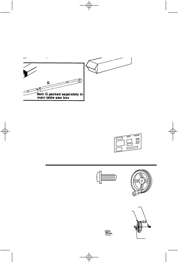
G |
Blade Wrench........................ |
2 |
S |
Rod Support .......................... |
1 |
H |
Wire Tie ................................. |
3 |
T |
Operators Manuals |
|
J |
Handwheel............................. |
2 |
Fence Guide Bar Carton Containing: |
||
K |
Foot Stiffener ............................. |
4 |
U |
Front Fence Guide Bar.......... |
1 |
|
|
|
V |
Rear Fence Guide Bar .......... |
1 |
|
|
|
W |
Bag Loose Parts.................... |
1 |
|
R |
A |
B |
|
Fence Guide Bar Carton |
U
V
W
|
Blade Guard |
|
Rip Fence |
|
|
|
|
L |
|
|
|
S |
|
|
|
|
|
|
|
|
|
C |
|
|
|
F |
|
|
Motor |
|
|
|
|
|
D |
G |
|
|
M |
|
|
|
|
|
|
|
N |
P |
Q |
|
|
|
||
|
|
|
|
|
|
H |
|
|
|
E J
T
K
16
.SP6498 Belt Drive Saw 05/03 7/15/03 7:04 AM Page 17
Herc-U-Lift™ Caster Carton |
|
Item |
Description |
Qty. |
|
Item |
Description |
Qty. |
|||
A |
Channel Rear ....................... |
1 |
E |
Tube Front 13-7/8" Long |
.......2 |
B |
Tube U-Bolt 19-5/8" Long...... |
1 |
F |
Caster Swivel 3" .................... |
4 |
C |
Tube Support 17-1/4" Long ...1 |
G |
Tube Rear 27" Long .............. |
2 |
|
D |
Plate Assembly...................... |
1 |
H |
Blister Pack - Hardware ........ |
1 |
Loose Parts
G
H
Assembly
Installing Bevel Handwheel
1. Locate the following hardware:
1 Pan Head Screw with Lockwasher, 1/4-20 x 5/8" long
1 Lockwashers, 1/4 External Type From among the loose parts, find the following:
2Handwheels
2.Line up flat spots on shaft and hand-wheel, push handwheel onto shaft. Install screw and lockwasher to lock handwheel on shaft. Repeat for the other handwheel.
1/4-20 x 5/8
Pan Head Screw with Lockwasher
Handwheel
Pan Head Screw with Lockwasher
Bevel Handwheel
Shaft
17
.SP6498 Belt Drive Saw 05/03 7/15/03 7:04 AM Page 18
Assembly (continued)
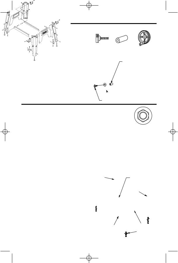
Installing Elevation Handwheel
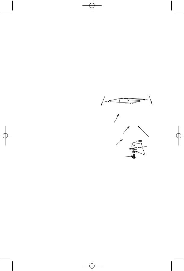
1.Locate the following hardware:
1Handwheel
1Elevation Lock Knob
1Elevation Lock Tube
2.Slide elevation lock tube onto elevation shaft.
3.Line up flat spots on shaft and handwheel, push handwheel onto shaft.
4.Screw elevation lock knob onto shaft. Do not tighten at this time.
Elevation Elevation Handwheel
Lock Knob Lock Tube
Elevation
Lock Tube
 Elevation Handwheel
Elevation Lock Knob
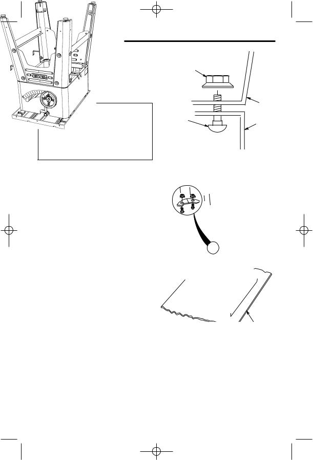
Assembling Leg Stand
1.Locate the leg stand.
Remove all parts from packing material.
2.Locate the following hardware:
23Truss Head Screws, 5/16-18 x 5/8” long
23Serrated Flange Hex Nuts, 5/16-18
4Leveling Feet
83/8-16 Hex Nut
3.Locate the following:
4Legs
2 End Panels
2 Leg Braces
1Miter Gauge Storage Hook
2Rip Fence Storage Hooks
4Foot Stiffeners
5/16-18 x 1/2 In. |
5/16-18 Serrated |
|
Head Screw |
||
Flange Hex Nut |
3/8-16 |
Leveling |
|
Foot |
Rip Fence |
|
Hex Nut |
|
|
|
Storage Hooks |
|
|
|
Leg |
Leg |
|
Braces |
Rip Fence
Storage
Hook
Miter Gauge |
End Panel |
Storage Hook |
Foot |
|
|
|
Stiffener |
18
.SP6498 Belt Drive Saw 05/03 7/15/03 7:04 AM Page 19
4.Assemble the legs as shown. Insert the screws through the holes in the legs, then through the holes in the end panels. Attach miter gauge and rip fence storage hooks as shown.
Legs must be assembled on top of panels.
5.Screw on the serrated flange hex nuts hand tight.
6.Insert the screws through the holes in the legs, then through the holes in the leg braces.
7.Screw on the serrated flange hex nuts but do not tighten until completely assembled.
8.Install leveling feet through holes in foot stiffeners and bottom of legs as shown. Adjust feet all the way up to bottom of leg.
9.Once you have completed the entire assembly process, move saw to desired location and adjust
the four leveling feet to support the tool as follows:
a.With 9/16" wrench loosen bottom nut.
b.Back off top nut by hand.
c.Raise or lower foot by adjusting bottom nut using 9/16" wrench.
d.Snug top nut against inside of leg by hand.
e.Tighten all four bottom nuts using 9/16" wrench.
Miter Gauge |
Rip Fence |
Storage Hook |
Storage Hook |
End |
|
Panel |
|
Screw Head |
Leg |
|
|
|
Brace |
Herc-U-Lift |
Foot |
|
Systems Will |
||
Stiffener |
||
Be Installed Here |
||
3/8-16 |
||
Leveling Foot |
||
Hex Nuts |
||
|
19
.SP6498 Belt Drive Saw 05/03 7/15/03 7:04 AM Page 20
Assembly (continued)
Mounting Your Saw
1.Place the saw upside down onto a smooth piece of cardboard or heavy paper, on the floor, so the saw is resting on the table top.
WARNING: The saw is heavy. To reduce the risk of back injury, get help to lift the saw. Hold the saw close to your body. Bend your knees so you can lift with your legs, not your back.
2.Place legs on saw so that holes in saw base and leg set line up and trim label is facing front.
3.Install screws and serrated flange hex nuts as shown.
4.Tighten all leg assembly and mounting hardware at this time.
Serrated
Flange
Hex Nut
|
Leg |
Screw |
Base |
|
Typical On
Each Leg
20
.SP6498 Belt Drive Saw 05/03 7/15/03 7:04 AM Page 21
Assembling Table Extensions
1.From the blister pack locate the following hardware: (Quantity indicated is for two extensions)
8Hex Head Screws, 5/16-18 x 3/4" Long with washers
NOTE: Assemble with saw upside down.
WARNING: Stock table extensions must be installed. They help support the fence guide bars. An unsupported guide bar can twist. Twisted guide bars can misalign fence. A misaligned fence can cause binding or kickback. You could be hit or cut.
2.Insert four (4) 5/16-18 x 3/4 in. long screws with washers through the holes in each extension and screw into the table. Do not tighten.
3.Repeat step 2 to install the other extension.
4.Stand saw upright on legs. Roll saw over onto front then up onto feet.
WARNING: The saw is heavy. To reduce the risk of back injury, get help to lift the saw. Hold the saw close to your body. Bend your knees so you can lift with your legs, not your back.
5.Line up the front edge of extension with the front edge of the table. At the spots marked “X” in the drawing, tighten a “C” Clamp over the edge of table and extension. Use a combination square to check the alignment of the front and top edges nearest the “X”’s. Tighten the two corner nuts only with a 1/2" wrench.
NOTE: This assembly may also be done without the use of a “C” Clamp.
5/16-18 x 3/4 In.
Hex Head Screw
With Washers
Hex
Screw
With
Washers
"C" Clamps
 Align Front Edges
21
.SP6498 Belt Drive Saw 05/03 7/15/03 7:04 AM Page 22
Assembly (continued)
WARNING: Table extensions must be installed. Front edge of table and extensions must be lined up. An uneven front edge can twist the fence guide bar. Twisted guide bars can misalign fence. A misaligned fence can cause binding or kickback. You could be hit or cut.
6.Tighten a “C” clamp over the edge of table and extension at the center until the extension is even with the table surface as shown. Tighten the two center nuts with a 1/2" wrench.
7.Repeat steps 5 and 6 to align the other extension.
"C" Clamp
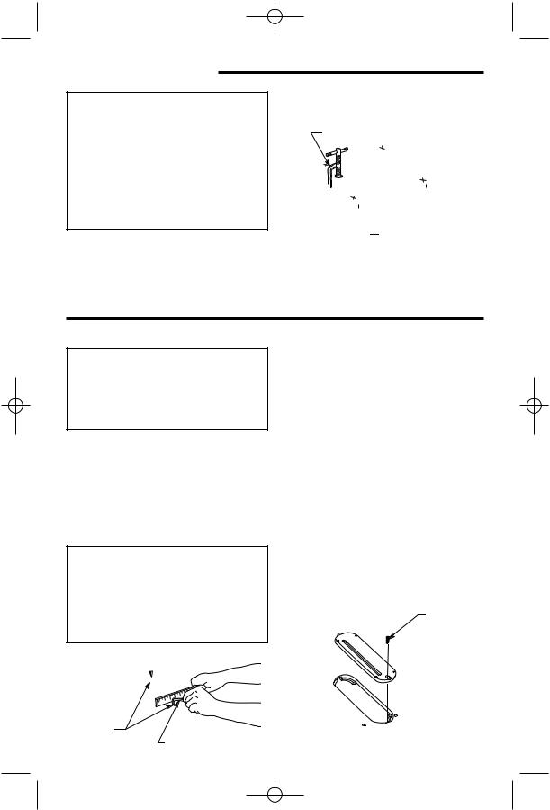
Checking Table Insert
WARNING: To reduce the risk of injury from accidental start, make sure switch is “OFF” and plug is not connected to power source outlet.
1.Insert should be flush with table top. Check as shown. Loosen flat head screw that holds insert and adjust the four set screws as necessary. Tighten flat head screw. Do not tighten screw to the point where it bends the insert.
CAUTION: Insert must be even with the table surface. Inserts too high or low can let the workpiece “snag” or catch on uneven edges. Workpiece could twist and kickback.
 Table Insert
Set
Screws
3/32" Hex
"L" Wrench
2. To remove insert.
a.Make sure saw is off and unplugged.
b.Loosen flat head screw.
c.Lift insert from front end, and pull toward front of saw.
d.To replace insert.
e.Make sure saw is off and unplugged.
f.Place insert into insert opening in table and push toward rear of saw to engage spring clip and until keyslot in insert will drop over flat head screw. Tighten screw.
g.Do not tighten screw to the point where it bends the insert.
Flat Head
Screw
22
.SP6498 Belt Drive Saw 05/03 7/15/03 7:04 AM Page 23
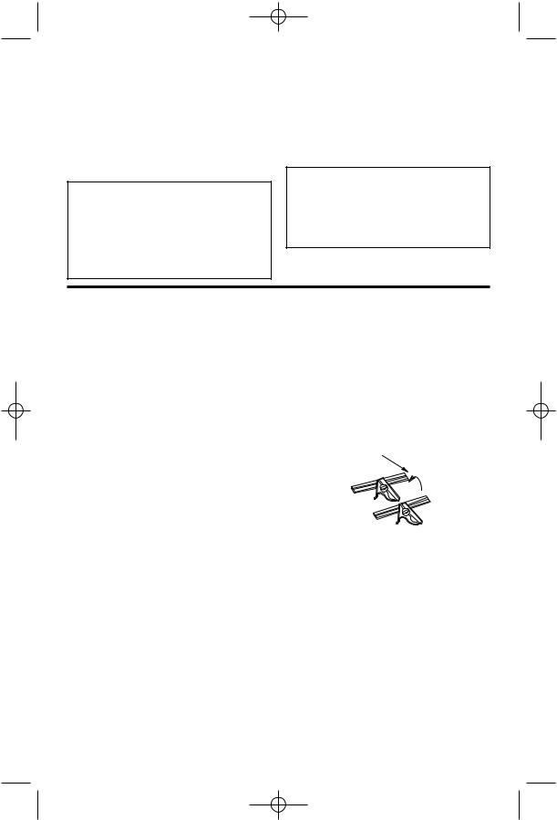
Checking Heeling Adjustment or Parallelism of Sawblade to Miter Gauge Groove
While cutting, the material must move in a straight line parallel to the sawblade. Therefore, both the miter gauge groove and the rip fence must be parallel to the sawblade.
WARNING: The blade must be parallel to the miter gauge groove. Misaligned blades could bind on workpiece. Workpiece could suddenly kickback. You could be cut or hit.
If the sawblade is not parallel to the miter gauge groove, the blade will bind at one end of the cut. This is known as “Heeling”.
WARNING: To reduce the risk of injury from accidental start, make sure switch is “OFF” and plug is not connected to power source outlet.
To check for parallelism:
1.Raise blade to approximately 3" depth of cut.
2.Mark an “X” on one tooth.
3.Place the head of a combination square in the left miter gauge groove. Rotate the blade so that the tooth marked with an “X” is at the front and adjust the blade of the square so that it just touches the tip of the marked tooth. Lock the square at this setting.
NOTE: Hold the head of the combination square firmly against the edge of the miter gauge groove during all measurements.
4.Move the square to the rear of the blade. Rotate the blade so the marked tooth is at the rear and see if the marked tooth again touches the blade of the square.
5.If the marked tooth touches the square at the front and at the rear of the sawblade, the blade is parallel to miter gauge slot. The parallelism is correct. Proceed to the “Checking Blade Tilt, or Squareness of Blade to Table”.
6.If square does not touch the marked tooth at the rear and front equally (gap is greater that 0.015 inch–thickness of 4 pages from Owners Manual) or tooth interferes with square, the mechanism underneath must be adjusted to make the blade parallel to the miter gauge groove.
Sawblade
Combination
Square 

Miter Gauge 
Groove
23
 Loading...