


Hardware Guide
1Guide to the Printer
2Installing Options
3Connecting the Printer
4Configuration
5Paper and Other Media
6Replacing Consumables and Maintenance Kit
7Cleaning the Printer
8Adjusting the Printer
9Troubleshooting
10Removing Misfed Paper
11Appendix
Read this manual carefully before you use this machine and keep it handy for future reference. For safe and correct use, be sure to read the Safety Information before using the machine.
Trademarks
Microsoft, Windows and Windows NT are registered trademarks of Microsoft Corporation in the United States and/or other countries.
Adobe®, PostScript®, Acrobat®, PageMaker® and Adobe Type Manager are registered trademarks of Adobe Systems Incorporated.
PCL® is a registered trademark of Hewlett-Packard Company.
Apple, AppleTalk, EtherTalk, Macintosh, Mac OS, and True Type are trademarks of Apple Computer, Inc., registered in the U.S. and other countries.
IPS-PRINT Printer Language Emulation Copyright© 1999-2000 Oak Technology, Inc., All rights reserved.
The Bluetooth® word mark and logos are owned by the Bluetooth SIG, Inc. and any use of such marks by Ricoh Company, Ltd. is under license.
NetWare is a registered trademark of Novell, Inc.
PictBridge is a trademark.
Other product names used herein are for identification purposes only and might be trademarks of their respective companies. We disclaim any and all rights to those marks.
The proper names of the Windows operating systems are as follows:
•Microsoft® Windows® 95 operating system
•Microsoft® Windows® 98 operating system
•Microsoft® Windows® Millennium Edition (Windows Me)
•The product names of Windows® 2000 are as follows: Microsoft® Windows® 2000 Advanced Server Microsoft® Windows® 2000 Server
Microsoft® Windows® 2000 Professional
•The product names of Windows® XP are as follows: Microsoft® Windows® XP Professional
Microsoft® Windows® XP Home Edition
•The product names of Windows ServerTM 2003 are as follows: Microsoft® Windows ServerTM 2003 Standard Edition Microsoft® Windows ServerTM 2003 Enterprise Edition Microsoft® Windows ServerTM 2003 Web Edition
•The product names of Windows NT® 4.0 are as follows: Microsoft® Windows NT® Server 4.0
Microsoft® Windows NT® Workstation 4.0
i

Positions of RWARNING and RCAUTION labels
This machine has labels for RWARNING and RCAUTION at the positions shown below. For safety, please follow the instructions and handle the machine as indicated.
AQC0
High temperature parts. Turn off the main power and be careful when replacing fusing unit/removing misfed paper.
The inside of this printer becomes very hot. Do not touch parts labelled “v” (indicating a hot surface). Touching these parts will result in burns.
ii

Do not incinerate used toner or toner containers. Toner dust might ignite when exposed to an open flame.
Do not incinerate spilled toner or used toner. Toner dust is flammable and might ignite when exposed to an open flame.
Disposal should take place at an authorized dealer or an appropriate collection site.
If you dispose of the used toner containers yourself, dispose of them according to local regulations.
iii
Manuals for This Printer
For particular functions, see the relevant parts of the manual.
Safety Information
Provides information on safe usage of this machine.
To avoid injury and prevent damage to the machine, be sure to read this.
Quick Installation Guide
Contains procedures for removing the printer from its box, connecting it to a computer, and installing its driver.
Hardware Guide
Contains information about paper and procedures such as installing options, replacing consumables, responding to error messages, and resolving jams.
Software Guide
Contain procedures for using this machine in a network environment, utilizing the software, and using security functions.
Security Guide
This manual is for administrators of the machine. It explains security functions that the administrators can use to protect data from being tampered, or prevent the machine from unauthorized use. Also refer to this manual for the procedures for registering administrators, as well as setting user and administrator authentication.
iv

How to Read This Manual
Symbols
This manual uses the following symbols:
Indicates important safety notes.
Ignoring these notes could result in serious injury or death. Be sure to read these notes. They can be found in the Safety Information.
Indicates important safety notes.
Ignoring these notes could result in moderate or minor injury, or damage to the machine or to property. Be sure to read these notes. They can be found in the Safety Information.
Indicates points to pay attention to when using the machine, and explanations of likely causes of paper misfeeds, damage to originals, or loss of data. Be sure to read these explanations.
Indicates supplementary explanations of the machine’s functions, and instructions on resolving user errors.
This symbol is located at the end of sections. It indicates where you can find further relevant information.
[ ]
Indicates the names of keys that appear on the machine’s display panel.
{}
Indicates the names of keys on the machine’s control panel.
v
Description for the Specified Model
In this manual, the following items explain about the printer for the specified models:
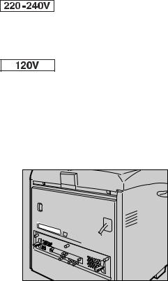
This explains about the 220–240 V model printer. You can identify the model by checking the label on the rear of the printer.
Read if you purchase this model.
This explains about the 120 V model printer. You can identify the model by checking the label on the rear of the printer.
Read if you purchase this model.

 Note
Note
You can identify the printer's model by checking the label on the rear of the printer as shown.
AQC065S |
vi
Installing the Operating Instructions
The CD-ROM “Manuals” provided with the printer contains an HTML Operating Instructions Manual in HTML version. Follow this instructions to install it.
 Important
System Requirements :
•Windows 95/98/Me, Windows 2000/XP, Windows Server 2003 or Windows NT4.0.
•800 × 600 or higher monitor resolution.
Web Browsers :
•Microsoft Internet Explorer 5.5 SP2 or higher
•Firefox 1.0 or higher
A B
Quit all applications currently running.
Insert the CD-ROM “Manuals” into the CD-ROM drive.
The installer starts.
Auto Run may not work under certain operating system setting. If this is the case, launch “Setup.exe” on the CD-ROM root directory.
C D E F G
Select an interface language, and then click [OK].
Click [Install manuals].
Follow the instructions on the screen to complete the installation.
Click [Finish] when the installation is completed.
Click [Exit].

 Note
Note
Auto Run may not work under certain operating system setting. If this is the case, copy all data on the CD-ROM root directory to your hard disk drive, and then launch “Setup.exe” to start the installation.
To uninstall the Operating Instructions Manual, select [Programs] in the [Start] menu, select your printer driver, and then click [uninstall]. You can uninstall each Manual Guide separately.
If you are using an incompatible Web browser and the simpler version of the Operating Instructions Manual does not display correctly, open the folder “MANUALLANG (language) \ (manual name) unv” on the CDROM “Manuals”, and then double-click on “index.htm”.
vii

TABLE OF CONTENTS |
|
Trademarks.............................................................................................................. |
i |
Positions of RWARNING and RCAUTION labels .............................................. |
ii |
Manuals for This Printer....................................................................................... |
iv |
How to Read This Manual ..................................................................................... |
v |
Symbols ..................................................................................................................... |
v |
Description for the Specified Model.................................................................... |
vi |
Installing the Operating Instructions ................................................................. |
vii |
1. Guide to the Printer |
|
Exterior: Front View............................................................................................... |
1 |
Exterior: Rear View ................................................................................................ |
3 |
Inside....................................................................................................................... |
4 |
Control Panel.......................................................................................................... |
5 |
Display Panel.......................................................................................................... |
7 |
Reading the Display and Using Keys......................................................................... |
7 |
2. Installing Options |
|
Available Options................................................................................................... |
9 |
Option List .................................................................................................................. |
9 |
Option Installation Flow Chart .................................................................................. |
10 |
Installing Options...................................................................................................... |
11 |
Caution when re-installing the controller board........................................................ |
13 |
Attaching Paper Feed Unit Type 4000................................................................ |
14 |
Attaching Memory Unit Type D 128MB, Memory Unit Type E 256MB (SDRAM |
|
Module) ............................................................................................................... |
17 |
Attaching User Account Enhance Unit Type E ................................................. |
22 |
Attaching Hard Disk Drive Type 4000 ................................................................ |
27 |
Attaching IEEE 802.11b Interface Unit ............................................................... |
33 |
Attaching Bluetooth Interface Unit Type 3245 .................................................. |
36 |
Attaching IEEE 1284 Interface Board Type A.................................................... |
39 |
Attaching the USB Host Interface Board Type A .............................................. |
41 |
Attaching Gigabit Ethernet Board Type A ......................................................... |
43 |
Attaching Data Overwrite Security Unit Type E ................................................ |
46 |
Attaching the Camera Direct Print Card ............................................................ |
48 |
Attaching VM Card Type D.................................................................................. |
50 |
Attaching Data Storage Card Type A ................................................................. |
52 |
3. Connecting the Printer |
|
Network Connection ............................................................................................ |
55 |
Reading the LED Lamps .......................................................................................... |
57 |
USB Connection................................................................................................... |
58 |
Connecting a digital camera ............................................................................... |
59 |
Parallel Connection ............................................................................................. |
61 |
viii
4. Configuration |
|
Ethernet Configuration........................................................................................ |
63 |
Using DHCP - Detecting the Network Address Automatically.................................. |
67 |
Making Network Settings for Using Netware............................................................ |
69 |
IEEE 802.11b (Wireless LAN) Configuration ..................................................... |
71 |
5. Paper and Other Media |
|
Paper and Other Media Supported by This Printer........................................... |
77 |
Paper Recommendations.................................................................................... |
81 |
Loading Paper.......................................................................................................... |
81 |
Storing Paper ........................................................................................................... |
81 |
Types of Paper and Other Media ............................................................................. |
82 |
Paper not supported by this printer .......................................................................... |
87 |
Print Area ................................................................................................................. |
88 |
Loading Paper ...................................................................................................... |
89 |
Loading Paper in Tray 1 and the optional paper feed unit ....................................... |
89 |
Loading Paper in the Bypass Tray ........................................................................... |
97 |
Switching between Paper Trays............................................................................. |
104 |
6. Replacing Consumables and Maintenance Kit |
|
Replacing the Toner Cartridge ......................................................................... |
105 |
Replacing the Photo Conductor Unit ............................................................... |
109 |
Replacing the Intermediate Transfer Unit........................................................ |
115 |
Replacing the Waste Toner Bottle.................................................................... |
120 |
Replacing the Maintenance Kit......................................................................... |
123 |
Before Replacing.................................................................................................... |
123 |
Replacing the Friction Pad ..................................................................................... |
124 |
Replacing the Paper Feed Roller ........................................................................... |
126 |
Replacing the Transfer Roller ................................................................................ |
128 |
Replacing the Fusing Unit ...................................................................................... |
130 |
Replacing the Dustproof Filter................................................................................ |
132 |
7. Cleaning the Printer |
|
Cautions to Take When Cleaning ..................................................................... |
135 |
Cleaning the Friction Pad.................................................................................. |
136 |
Cleaning the Paper Feed Roller........................................................................ |
138 |
Cleaning the Registration Roller ...................................................................... |
141 |
8. Adjusting the Printer |
|
Adjusting the Color Registration...................................................................... |
143 |
Correcting the Color Gradation ........................................................................ |
145 |
Set the Gradation Correction Value ....................................................................... |
146 |
Viewing the Color Calibration Sample Sheet and Gradation Correction Sheet ..... |
149 |
Resetting the gradation correction value to the initial value................................... |
151 |
Adjusting Tray Registration.............................................................................. |
152 |
ix

9. Troubleshooting |
|
Error & Status Messages on the Control Panel .............................................. |
155 |
Panel Tone.......................................................................................................... |
157 |
Printer Does Not Print ....................................................................................... |
158 |
Checking the port connection................................................................................. |
160 |
Other Printing Problems ................................................................................... |
162 |
Additional Troubleshooting .............................................................................. |
168 |
10.Removing Misfed Paper |
|
Removing Misfed Paper .................................................................................... |
171 |
When the Paper Misfeed Message Appears (Cover A)................................... |
172 |
When the Paper Misfeed Message Appears (Cover Z) ................................... |
175 |
11.Appendix |
|
Moving and Transporting the Printer............................................................... |
177 |
Moving the Printer .................................................................................................. |
178 |
Consumables ..................................................................................................... |
179 |
Toner Cartridge ...................................................................................................... |
179 |
Waste Toner Bottle ................................................................................................ |
180 |
Photo Conductor Unit............................................................................................. |
180 |
Intermediate Transfer Unit (Transfer Unit) ............................................................. |
181 |
Maintenance Kit ..................................................................................................... |
181 |
Specifications..................................................................................................... |
182 |
Mainframe .............................................................................................................. |
182 |
Options................................................................................................................... |
185 |
INDEX....................................................................................................... |
189 |
x
1. Guide to the Printer
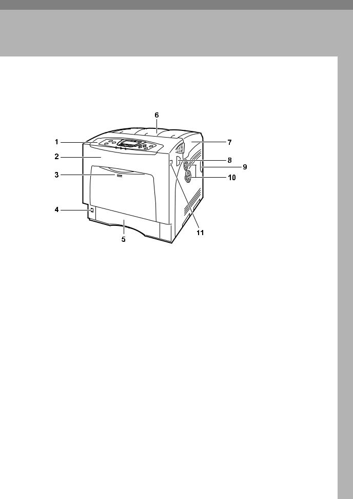
Exterior: Front View
|
AQC021S |
1. Control Panel |
4. Power Switch |
Contains keys for printer control and a display that shows the printer status.
2. Front Cover
Open the front cover to replace the fusing unit or transfer roller, or to remove jammed paper.
The front cover can be opened in two ways:
To replace the fusing unit or roller, pull the levers marked “A” on either side of the printer. To remove jammed paper, press the button marked “Z” on the right side of the printer.
3. Bypass Tray
Up to 100 sheets of plain paper can be loaded.
Use this switch to turn the power on and off.
5. Tray 1
Up to 550 sheets of plain paper can be loaded.
6. Standard Tray
Output is stacked here with the print side down.
7. Top Cover
Open this cover when replacing the toner cartridge.
8.Front Cover (A) Open Levers
9.Intake Port
1
Guide to the Printer
10. Ventilator
Releases heat from internal components to prevent overheating. Malfunctions occur if the vent is blocked or obstructed.
1 |
The dustproof filter needs to be replaced |
|
regularly for proper maintenance. |
||
|
11. Front Cover (Z) Open Button

 Note
Note
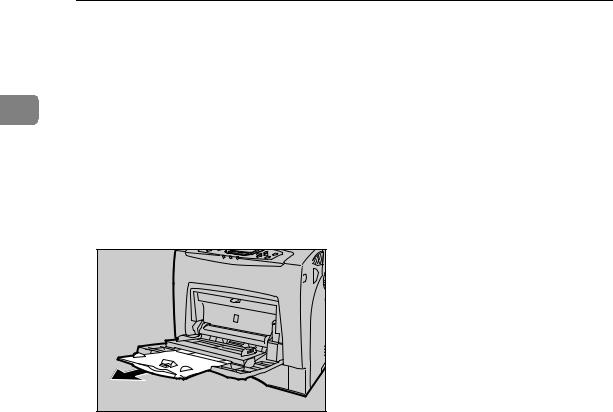
When setting paper larger than A5 K, pull out the paper extender as shown. For details about the sizes and types of paper that can be used, see p.77 “Paper and Other Media Supported by This Printer”.
AQC022S |
2
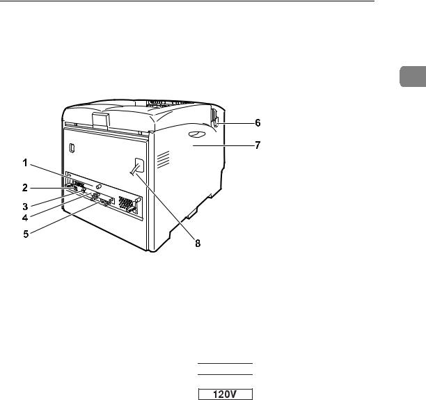
Exterior: Rear View
Exterior: Rear View
1
1. Controller Board
Slide this out to install options such as the memory unit, user account enhance unit or printer hard disk. Plug cables such as the USB cable and Ethernet cable into their connectors.
2. Ethernet Port
Use a network interface cable to connect the printer to the network.
3. USB Port
Use a USB cable to connect the printer to the host computer.
4. Optional Interface Board Slots
AQC200S
6.Front Cover (A) Open Levers
7.Left Cover
Open this cover when replacing the photo conductor unit (PCU), intermediate transfer unit or waste toner cartridge.
8. Power Cable


 The power cable is separated. Connect the power cable to the printer.
The power cable is fixed to the back side.
Insert an optional IEEE 802.11b interface unit, wireless interface board, or 1284 interface board in this slot. Up to two interface board can be inserted at a time.
5. Expansion Card Slots
Install expansion cards in these slots. There are three slots.
When you use the expansion card, use the center slot.
3
Guide to the Printer
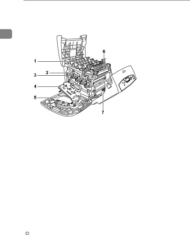
Inside
1
AQC023S
1. Toner Cartridge |
4. Inner Cover |
Loads from the printer rear, in the order of yellow (Y), cyan (C), magenta (M), and black (K).
If the message which prompts you to replace toner appears on the screen, replace the indicated color of the toner cartridge.
2. Intermediate Transfer Unit (Transfer Unit)
If the message which prompts you to replace it appears on the display, replace the transfer unit .
3. Photo Conductor Unit
If the message which prompts you to replace it appears on the display, replace the photo conductor unit.

 Reference
Open this when replacing the photo conductor units or intermediate transfer unit.
5. Waste Toner Bottle
Collects toner that is wasted during printing.
If the message which prompts you to replace it appears on the display, replace the waste toner bottle.
6. Fusing Unit
If the message which prompts you to replace it appears on the display, replace the fusing unit.
7. Transfer Roller
If the message which prompts you to replace it appears on the display, replace the transfer roller.
For details about the messages which appear on the screen to prompt you to replace the units, see p.155 “Error & Status Messages on the Control Panel”.
4

Control Panel
Control Panel
1
AQC024S
1. Display |
5. {Menu} key |
Displays current printer status and error messages.
For details about error messages, see p.155 “Error & Status Messages on the Control Panel”.
2. Selection keys
Press this key to make and check the current printer settings.
For details, See “Making Printer Settings Using the Control Panel”, Software Guide.
6. Power indicator
Correspond to the function items at the bottom line on the display.
Example: In the initial screen, when the instruction “press [Option]” appears in this manual, press the left selection key.
3. {Online} key
Indicates whether the printer is online or offline. Press this to switch between online and offline.
When the lamp is lit, the printer is online, enabling data reception from the host computer.
When the lamp is unlit, the printer is offline, disabling data reception from the host computer.
Press to return to the ready condition.
4. {Job Reset} key
When the printer is online, press this key to cancel an ongoing print job.
This indicator remains lit while the power is on. It is unlit when the power is off or while the printer is in the Energy Saver mode.
7. Alert indicator
Lights up whenever a printer error occurs. A red light indicates an error has occurred that makes printing impossible; the yellow light indicates a potential error during printing.
If the red light is on, follow the instructions that appear on the display.
8. Data In indicator
Blinks when the printer is receiving data from a computer. The Data In indicator is lit if there is data to be printed.
9. Scroll keys
Press to move the cursor in each direction, step by step.
When the {U}, {T}, {V}, or {W} key appears in this manual, press the scroll key of the same direction.
5

Guide to the Printer
10. {OK} key
Press this key to execute menu items selected on the display.
11. {Escape} key
1Press this key to return to the previous condition on the display.
6

Display Panel
Display Panel
This section describes configuration using the display panel on the initial screen.
1
1. Operational status or messages
Displays current machine status, such as “Ready”, “Offline”, and “Printing...”.
2. [Option]
Press to display the status of options installed in the printer.
AQC060S
3. [Prt.Jobs]
Press to display print jobs sent from a computer.
For details, see Software Guide.
4. [Supplies]
Press to display the menu of supplies fir the printer.
Reading the Display and Using Keys
This section explains how to read the display and using the selection key for the initial display.
1 |
2 |
43
|
AQC061S |
1. {Escape} key |
4. Selection keys |
Press to cancel an operation or return to the previous display.
2. {OK} key
Press to set a selected item or entered numeric value.
3. Scroll keys
Press to move the cursor in each direction, step by step.
When the {U}, {T}, {V}, or {W} key appears in this manual, press the scroll key of the same direction.
Correspond to the function items at the bottom line on the display.
Example: In the initial screen, when the instruction “press [Option]” appears in this manual, press the left selection key.
7

Guide to the Printer
1
8
2. Installing Options
Available Options
This section describes how to install options.
By installing options, you can improve the printer performance and have an expanded variety of features to use. For the specifications of each option, see p.182 “Specifications”.
RCAUTION:
•Before installing options, the machine should be turned off and unplugged for at least an hour. Components inside the machine become very hot, and can cause a burn if touched.
•Before moving the machine, unplug the power cable from the outlet. If the cable is unplugged abruptly, it could become damaged. Damaged plugs or cables can cause an electrical or fire hazard.
•When lifting the machine, use the grips on both sides. The machine could break or cause an injury if dropped.
 Important
The voltage rating of the connector for options is 24 V DC or less.
Option List
The following is a list of options for this printer.
|
The 25 ppm model printer |
The 30 ppm model printer |
|
|
|
Paper Feed Unit Type 4000 |
Available |
Available |
|
|
|
Hard Disk Drive Type 4000 |
Available |
Available |
|
|
|
Memory Unit Type D 128MB |
Available |
Available |
|
|
|
Memory Unit Type E 256MB |
Available |
Available |
|
|
|
IEEE 802.11b Interface Unit |
Available |
Available |
|
|
|
IEEE 1284 Interface Board Type A |
Available |
Available |
|
|
|
BluetoothInterfaceUnitType3245 |
Available |
Available |
|
|
|
UserAccountEnhanceUnitTypeE |
Available |
Available |
|
|
|
USB Host Interface Board Type A |
Available |
Available |
|
|
|
Gigabit Ethernet Board Type A |
Available |
Available |
|
|
|
Camera Direct Print Card Type B |
Available |
Available |
|
|
|
DataOverwriteSecurityUnitTypeE |
Available |
Available |
|
|
|
VM Card Type D |
Available |
Available |
|
|
|
Data Storage Card Type A |
Available |
Available |
9

Installing Options
Option Installation Flow Chart
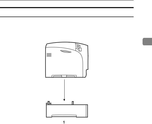
Installing multiple options in the following order is recommended:
A Attach the paper feed unit (Paper Feed Unit Type 4000).
Attach the paper feed units to the bottom of the printer.
2 |
You can attach up to two paper feed units. Up to 1750 sheets of paper can be |
loaded in total. |
B Install the SDRAM module (Memory Unit Type D 128MB, Memory Unit Type E 256MB).
Install the module to the SDRAM module slot on the controller board. There are two types of memory unit: 128 MB and 256 MB.
C Install User Account Enhance Unit (User Account Enhance Unit Type E).
Install the module to the User Account Enhance Unit slot of the controller board.
D E
Install the hard disk drive (Hard Disk Drive Type 4000).
Install the hard disk drive to the controller board.
Install the IEEE 1284 interface board, IEEE 802.11b interface unit, Bluetooth interface unit, USB host interface board, or Gigabit Ethernet board.
Install the IEEE 1284 interface board, IEEE 802.11b interface unit, Bluetooth interface unit, USB host interface board, or Gigabit Ethernet board on the controller board.
Up to two of the followings can be installed:
•IEEE 1284 Interface Board Type A
•IEEE 802.11b Interface Unit
•Bluetooth Interface Unit Type 3245
•USB Host Interface Board Type A
•Gigabit Ethernet Board Type A
F Install the security unit (Data Overwrite Security Unit Type E, Data Storage Card Type A), the Camera Direct Print card (Camera Direct Print Card Type B), or the VM card (VM Card Type D).
Insert these units into the SD card slot on the controller board.
10
Available Options
Installing Options
Install options in the positions shown in the illustration.
Exterior
2
AET061S
1. Paper Feed Unit Type 4000
Loads up to 550 sheets of paper.
Up to two paper feed units, can be installed on the printer. Installed tray units are identified as “Tray 2” and “Tray 3”.
See p.14 “Attaching Paper Feed Unit Type 4000”.
11

Installing Options
Interior
2
AQC040S
1. Memory Unit Type D 128MB/Memory Unit Type E 256MB (SDRAM module)
Install 128 MB or 256 MB SDRAM module into the controller board slot. See p.17 “Attaching Memory Unit Type D 128MB, Memory Unit Type E 256MB (SDRAM Module)”.
2.Optional boards
See p.33 “Attaching IEEE 802.11b Interface Unit”.
See p.36 “Attaching Bluetooth Interface Unit Type 3245”.
See p.39 “Attaching IEEE 1284 Interface Board Type A”.
See p.41 “Attaching the USB Host Interface Board Type A”.
See p.43 “Attaching Gigabit Ethernet Board Type A”.

 Note
Note
3.Optional units
See p.46 “Attaching Data Overwrite Security Unit Type E”.
See p.48 “Attaching the Camera Direct Print Card”.
See p.50 “Attaching VM Card Type D”.
See p.52 “Attaching Data Storage Card Type A”.
4.Hard Disk Drive Type 4000
See p.27 “Attaching Hard Disk Drive Type 4000”.
5.User Account Enhance Unit Type E
See p.22 “Attaching User Account Enhance Unit Type E”.
You can have two of the following types of extension board installed at the same time: IEEE 802.11b Interface Unit, Bluetooth Interface Unit Type 3245, IEEE 1284 Interface Board Type A, USB Host Interface Board Type A, and Gigabit Ethernet Board Type A.
Some printer models come with the Expansion Hard Disk Drive Unit and Data Overwrite Security Unit installed as default.

 Reference
For the specifications of each option, see p.182 “Specifications”.
12
Available Options
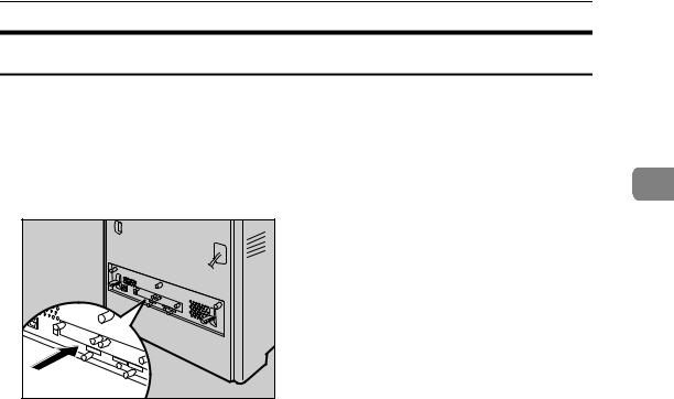
Caution when re-installing the controller board
This section describes handling the controller board when installing options.
If you slide out the controller board to install the SDRAM module, the user account enhance unit, or the printer hard disk, carefully follow the instruction below to re-install the controller board.
• Re-install the controller board into the printer by pushing the bottom center |
2 |
|
|
area of the board, as shown in the illustration. |
|
|
AQC004S |
 Important
The following may occur if the controller board is not properly installed:
•all control panel indicators are lit.
•no control panel indicators is lit.
•the “SC670” error message appears on the display.
13
Installing Options
Attaching Paper Feed Unit Type 4000
When installing multiple options, install the paper feed unit first.
RCAUTION:
•The printer weights approximately 50 kg (110.3 lb.). When moving the printer, use the inset grips on both sides, and lift slowly. The printer will break or
|
cause injury if dropped. |
2 |
RCAUTION:
• Lifting the paper feed unit carelessly or dropping it may cause injury.
 Important
Up to two paper feed units can be attached to the printer.
When two paper feed units are installed, they are detected as “Tray 2” and “Tray 3” starting from the upper unit.
Before using the new paper feed unit, you must make settings in the printer driver.
Check the printer nameplate to confirm the model code.
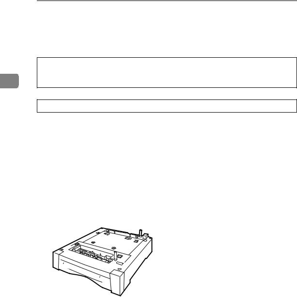
A Check the package contains the following:
Paper Feed Unit (including a paper tray)
AET108S
B C
Turn off the power, and then unplug the power cable.
Remove the orange fastening tapes from the paper feed unit.
14
Attaching Paper Feed Unit Type 4000
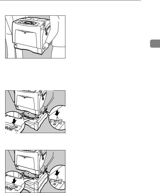
D Lift the printer using the inset grips on both sides of the printer.
2
AQC031S
 Important
The printer should always be lifted by at least two people.
E Align the printer with the two upright pins on the paper feed unit and then lower the printer slowly.
AET074S |
When installing two paper feed units, connect the two units first using the same procedure below before connecting the units to the printer.
AET075S |
15

|
|
Installing Options |
|
|
Note |
|
|
When moving the printer, remove the paper feed unit. |
|
|
After finishing installation, you can check whether the paper feed unit is |
|
|
properly installed: Print the configuration page from the [List/Test Print] |
|
|
menu. If it is installed properly, “Tray 2” or “Tray 2”, “Tray 3” will appear |
|
|
for “Connection Equipment” on the configuration page. |
|
|
If the paper feed unit is not installed properly, reinstall it following this |
2 |
|
|
|
procedure. If you cannot install it properly even after attempting reinstal- |
lation, contact your sales or service representative.

 Reference
For printing the configuration page, see “Test Printing”, Quick Installation
Guide.
For loading paper onto the paper tray, see p.89 “Loading Paper”.
When adjusting the printing position, see p.152 “Adjusting Tray Registration”.
16
Attaching Memory Unit Type D 128MB, Memory Unit Type E 256MB (SDRAM Module)
Attaching Memory Unit Type D 128MB, Memory Unit Type E 256MB (SDRAM Module)
RCAUTION: |
|
• Do not touch the inside of the controller board compartment. Doing so may |
|
cause a malfunction or a burn. |
2 |
|
 Important
Before touching the memory unit, ground yourself by touching something metal to discharge any static electricity. Static electricity can damage the memory unit.
Do not subject the memory unit to physical shocks.
Available memory varies depending on a model type.
Before using the new memory unit, Be sure to make settings in the printer driver.
A B
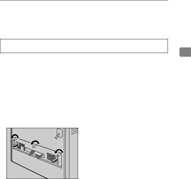
Turn off the power, and then unplug the power cable.
Loosen the three screws securing the controller board.
AQC630S |
The screws cannot be fully removed.
17
Installing Options
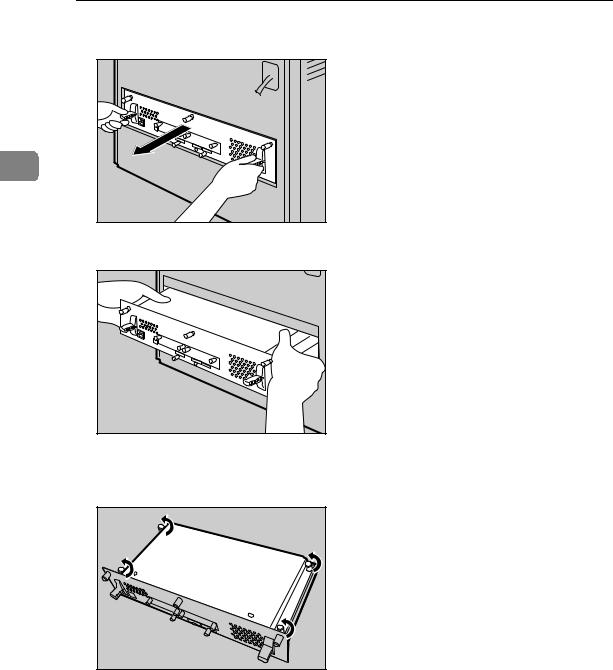
C Grasp the handles and carefully pull out the controller board.
2 |
AQC640S |
Using both hands, slide the controller board completely out.
AQC650S |
D Place the controller board on a flat surface, and then loosen the four screws to remove the cover.
AQC660S |
The screws cannot be fully removed.
18
 Loading...