


 Loading...
Ray218E & Ray55E
Marine VHF Radio
Owner’s Handbook
Document number: 81279-3
Date: April 2007
Trademarks and registered trademarks
Raymarine is a registered trademark of Raymarine plc.
All other product names are trademarks or registered trademarks of their respective owners.
Contents of this handbook © Raymarine 2007

|
|
3 |
Contents |
|
|
|
Trademarks and registered trademarks ............................................ |
2 |
About this Handbook ............................................................................................. |
9 |
|
Important Information ....................................................................................... |
10 |
|
|
Group MMSI ID .............................................................................. |
10 |
|
Antenna Mounting and EME Exposure ................................................ |
11 |
|
Safe Compass Distance ........................................................................ |
11 |
|
EMC Conformance ............................................................................... |
12 |
|
Duty Cycle ............................................................................................ |
12 |
Chapter 1: Introduction ..................................................................................... |
13 |
|
1.1 Ray218E and Ray55E Fixed Station VHF Radios ................................... |
13 |
|
1.2 |
Features ............................................................................................... |
13 |
|
Digital Selective Calling (DSC) .............................................................. |
14 |
Chapter 2: Installation ....................................................................................... |
15 |
|
2.1 |
Unpacking and Inspection .................................................................... |
15 |
|
Removing the Sun Cover ..................................................................... |
15 |
|
Equipment Supplied ............................................................................. |
16 |
2.2 |
Planning the Installation ...................................................................... |
17 |
2.3 |
Cable Connections ............................................................................. |
20 |
|
Power ................................................................................................ |
21 |
|
Hailer Horn (Ray218E only) .............................................................. |
22 |
|
External Speaker ............................................................................... |
22 |
|
Raymic / Mic Relocation ....................................................................... |
22 |
|
NMEA Data ........................................................................................ |
23 |
|
NMEA IN (from GPS) ...................................................................... |
24 |
|
NMEA OUT (to Chartplotter Display) .............................................. |
24 |
|
Antenna ............................................................................................... |
25 |
|
Grounding ............................................................................................ |
26 |
Chapter 3: General Operations ......................................................................... |
27 |
|
3.1 Keypad and Rotary Knobs .................................................................... |
27 |
|
|
Microphone Keys ................................................................................. |
28 |
|
1. PTT ......................................................................................... |
28 |
|
2. HILO / LOC DIST ......................................................................... |
28 |
|
3. 16/PLUS ............................................................................... |
28 |
|
4. UP/DOWN ............................................................................... |
28 |
|
5. SCAN / SAVE ............................................................................ |
28 |
|
Transceiver Controls ............................................................................. |
28 |
|
6. CH/OK ....................................................................................... |
28 |
|
7. PWR/VOL ................................................................................... |
28 |
|
8. SQ .............................................................................................. |
28 |

4 |
Ray218E and Ray55E Marine VHF Radios |
|
|
9. Soft Keys .................................................................................... |
29 |
|
Transceiver Push Keys ........................................................................... |
29 |
|
10. HAILER / INTCM (Ray218E only) ............................................. |
29 |
|
11. MENU/DSC ............................................................................. |
29 |
|
12. CLEAR .................................................................................... |
29 |
|
13. 16/PLUS .................................................................................. |
29 |
|
14. DISTRESS ................................................................................ |
29 |
|
Optional Raymic Second Station ........................................................... |
30 |
|
A. PTT ......................................................................................... |
30 |
|
B. VOL/SQ ..................................................................................... |
30 |
|
C. CLEAR ...................................................................................... |
31 |
|
D. 16/PLUS .................................................................................... |
31 |
|
E. Soft Keys ................................................................................... |
31 |
|
F. MENU / DSC .............................................................................. |
31 |
|
G. CH ............................................................................................ |
31 |
|
H. OK / INTCM .............................................................................. |
31 |
3.2 |
Transceiver LCD .................................................................................. |
32 |
|
1. (RX) Receiving ................................................................................ |
32 |
|
2. (TX) Transmitting ............................................................................ |
32 |
|
3. (HI/LO) TX Power ............................................................................ |
32 |
|
4. ATIS Active ..................................................................................... |
32 |
|
5. (SAVED) Memory Mode .................................................................. |
32 |
|
6. (LOCAL) Local/Distant Mode .......................................................... |
33 |
|
7. (FAV123) Favorite Channel ............................................................. |
33 |
|
8. Automatic Channel Changing Blocked ........................................... |
33 |
|
9. GPS ................................................................................................. |
33 |
|
10. DSC Call ....................................................................................... |
33 |
|
11. Weather Alert ............................................................................... |
33 |
|
12. Dot Matrix Display .......................................................................... |
33 |
|
13. (MAN) Manual Position Data .......................................................... |
33 |
|
14. Channel Status ............................................................................... |
34 |
|
15. Soft Key Labels ................................................................................ |
34 |
|
16. Channel Name ................................................................................ |
34 |
|
17. Channel Number ............................................................................ |
34 |
|
18. Channel Set .................................................................................... |
34 |
|
19. Signal Strength ............................................................................... |
34 |
|
Display Mode ....................................................................................... |
34 |

|
|
5 |
3.3 |
Alert Messages .................................................................................... |
35 |
3.4 |
Turning the Power ON and OFF .......................................................... |
35 |
3.5 |
Setting the Volume ............................................................................. |
36 |
3.6 |
Setting the Squelch ............................................................................ |
36 |
3.7 |
Tuning the Channel ............................................................................ |
36 |
3.8 |
Selecting a Weather Channel (If Licensed) ......................................... |
37 |
|
Weather Alert Operation (If Available) ......................................... |
37 |
3.9 |
Selecting the Priority Channel .............................................................. |
38 |
3.10 |
Selecting the Secondary Priority (PLUS) Channel .................................. |
38 |
|
Reprograming the Secondary Priority (PLUS) Channel ......................... |
39 |
3.11 |
Transmitting ....................................................................................... |
39 |
3.12 |
Menu Mode Operation ......................................................................... |
40 |
3.13 |
DSC Call Operation .............................................................................. |
40 |
Chapter 4: Menu Settings .................................................................................. |
41 |
|
4.1 |
Menu Function ................................................................................... |
41 |
|
Making Menu and Programming Selections ........................................ |
41 |
4.2 |
VHF Operations .................................................................................... |
44 |
|
Scan Mode ......................................................................................... |
44 |
|
All Scan ........................................................................................ |
45 |
|
Priority All Scan ............................................................................ |
46 |
|
Saved (Memory) Scan .................................................................. |
46 |
|
Priority Saved Scan ...................................................................... |
47 |
|
Display Mode ....................................................................................... |
47 |
|
Setting the Power Output (HI/LO) ........................................................ |
48 |
|
Saving Channels to Memory .............................................................. |
49 |
|
Using the Watch Modes ....................................................................... |
50 |
|
Dual Watch .................................................................................... |
50 |
|
Tri Watch ........................................................................................ |
50 |
|
Frequency Band ................................................................................... |
51 |
|
Channel Name ................................................................................... |
52 |
|
Favorite Channel ................................................................................ |
53 |
|
Sensitivity .......................................................................................... |
55 |
4.3 |
Hailer/Fog Horn/Intercom ..................................................................... |
55 |
|
Hailer (Ray218E only) ........................................................................... |
55 |
|
Fog Horn (Ray218E only) ...................................................................... |
56 |
|
Intercom ............................................................................................... |
57 |
4.4 |
GPS/Time Setup .................................................................................. |
58 |
|
Manual Position ................................................................................... |
58 |
|
Settings .............................................................................................. |
60 |
|
Latitude/Longitude Display .......................................................... |
60 |
|
Time Display ................................................................................ |
60 |
|
Time Offset .................................................................................. |
60 |

6 |
Ray218E and Ray55E Marine VHF Radios |
|
|
Time Format ................................................................................. |
60 |
|
COG/SOG Display ......................................................................... |
61 |
|
NMEA Output ..................................................................................... |
61 |
4.5 |
ATIS Operation ................................................................................. |
63 |
|
My ATIS ID .......................................................................................... |
63 |
|
ATIS Function ..................................................................................... |
65 |
4.6 |
System Configuration ........................................................................ |
66 |
|
Backlight Adjustment ......................................................................... |
66 |
|
Contrast Adjustment .......................................................................... |
66 |
|
Key Beep ............................................................................................. |
67 |
|
Signal Bar ........................................................................................... |
67 |
|
Bearing Mode ..................................................................................... |
67 |
|
Speed Unit .......................................................................................... |
68 |
|
System Test ......................................................................................... |
68 |
|
Version Number ................................................................................. |
69 |
|
Reset .................................................................................................. |
69 |
|
VHF OPS ......................................................................................... |
69 |
|
GPS SETUP ..................................................................................... |
69 |
|
SYSTEM CONFIG ............................................................................ |
70 |
|
DSC MENU ..................................................................................... |
70 |
Chapter 5: Digital Selective Calling (DSC) ...................................................... |
71 |
|
5.1 |
DSC Call Menu ................................................................................... |
71 |
|
Making DSC Menu and Programming Selections ................................. |
72 |
5.2 |
Distress Calls ...................................................................................... |
74 |
|
Sending a Distress Call ....................................................................... |
74 |
|
Undesignated (Quick) Distress Call ................................................ |
74 |
|
Designated Distress Call ............................................................... |
75 |
|
Transmitting ................................................................................... |
76 |
|
Receiving Acknowledgement ......................................................... |
76 |
|
Cancelling a Distress Call Made in Error ............................................... |
76 |
|
Receiving a Distress Call ..................................................................... |
77 |
|
Receiving a Distress Relay Sent by Another Station .............................. |
78 |
5.3 |
DSC Phonebook .................................................................................. |
78 |
|
Adding a new Entry ............................................................................ |
79 |
|
Editing an Existing Entry ..................................................................... |
80 |
|
Deleting an Existing Entry ................................................................... |
81 |
5.4 |
Individual Calls ................................................................................... |
81 |
|
Making DSC Calls to Coast Stations ...................................................... |
81 |
|
Transmitting an Individual Call ........................................................... |
81 |
|
Receiving Individual Calls ................................................................... |
83 |
5.5 |
Group Calls ......................................................................................... |
85 |
|
Group MMSI Setup ............................................................................. |
85 |

|
|
7 |
|
Adding a New Group ..................................................................... |
85 |
|
Transmitting a Group Call .................................................................. |
86 |
|
Receiving Group Calls ........................................................................ |
87 |
5.6 |
All Ships Calls ..................................................................................... |
89 |
|
Transmitting an All Ships Call ............................................................. |
89 |
|
Receiving an All Ships Call ................................................................. |
90 |
5.7 |
Position Request ................................................................................ |
91 |
|
Specifying the Target Vessel ............................................................... |
92 |
|
Retrieving the Last Received Position Data ........................................ |
93 |
|
Receiving a Position Request From Another Station ............................. |
93 |
5.8 |
Received Calls (Logs) ......................................................................... |
94 |
|
Log Entry Options ............................................................................... |
95 |
5.9 |
DSC Setup .......................................................................................... |
96 |
|
My MMSI ID ......................................................................................... |
96 |
|
Automatic Channel Changing for Incoming Calls ............................... |
98 |
|
Position Reply .................................................................................... |
99 |
Chapter 6: Customer Service .......................................................................... |
101 |
|
6.1 How to Contact Raymarine ................................................................ |
101 |
|
|
On the Internet ................................................................................... |
101 |
|
Customer Support ........................................................................ |
101 |
|
Product Repair and Service ................................................................. |
101 |
|
Technical Support ......................................................................... |
102 |
|
Accessories and Parts ................................................................... |
102 |
|
Worldwide Support ............................................................................ |
102 |
Appendix A: Specifications .............................................................................. |
103 |
|
|
General .............................................................................................. |
103 |
|
Transmitter ........................................................................................ |
104 |
|
Receiver ............................................................................................. |
104 |
Appendix B: Radio Controls ............................................................................. |
105 |
|
|
Microphone Keys ............................................................................... |
106 |
|
Transceiver Controls ........................................................................... |
106 |
|
Transceiver Push Keys ......................................................................... |
106 |
|
Optional Raymic Handset ................................................................... |
107 |
|
Raymic Keys ................................................................................. |
108 |
Appendix C: Menu Structure ............................................................................ |
109 |
|
Appendix D: Channel List ................................................................................ |
111 |
|
|
International Marine VHF Channels & Frequencies............................ |
111 |
|
U.S. Marine VHF Channels and Frequencies ....................................... |
114 |
|
Canadian Marine VHF Channels and Frequencies.............................. |
117 |
|
European Private Channels and Frequencies ...................................... |
122 |
8 |
Ray218E and Ray55E Marine VHF Radios |
Appendix E: Glossary |
........................................................................................123 |
Index ............................................................................................. |
125 |

9
About this Handbook
Intended Use
This handbook describes the Ray218E and Ray55E fixed VHF marine radios. The Ray218E and Ray55E provide two-way communications on all International marine channels, pre-set private channels, and (if programmed) all US and Canadian and marine channels. The Ray218E and Ray55E include equipment for Class “D” Digital Selective Calling (DSC).
Conventions Used
Throughout this handbook, the dedicated (labelled) keys are shown in bold capitals (for example: MENU/DSC). The LCD indicators and functions are shown in normal capitals (for example: TX).
Technical Accuracy
To the best of our knowledge, the information in this handbook was correct as it went to press. However, our policy of continuous product improvement and updating may change specifications without prior notice. As a result, unavoidable differences between the product and handbook may occur from time to time. Raymarine cannot accept liability for inaccuracies or omissions it may contain.
For the latest handbook revisions and product information visit our web site:
www.raymarine.com
Warranty
To register your new Raymarine product, please take a few minutes to fill out the warranty registration card found at the end of this handbook. It is very important that you complete the owner information and return the card to the factory in order to receive full warranty benefits.

10 |
Ray218E and Ray55E Marine VHF Radios |
Important Information
Licensing
Prior to using your Ray218E or Ray55E, please check your national requirements for both operators and equipment licensing.
Maritime Mobile Service Identity (MMSI)
The Ray218E and Ray55E include equipment for Class “D” Digital Selective Calling (DSC). A nine-digit Maritime Mobile Service Identity (MMSI) number is required to operate the DSC equipment. In some areas, a radio operator license is required before an MMSI number will be issued.
Note: You can request an MMSI number from the same agency that issues radio or Ship Radio licenses in your area. Once obtained, you can program the MMSI number into your Ray218E/Ray55E as described in this handbook.
Group MMSI ID
A Group ID MMSI number can also be entered for vessels that are part of a group, such as a flotilla or racing fleet, enabling DSC communications within the group.
Automatic Transmitter Identification System (ATIS)
If you purchased your Ray218E/Ray55E to include use on the inland waterways of the contracting governments of the “Regional Arrangement Concerning the Radiotelephone Service on Inland Waterways”— also known as the Basel Agreement1— your Ray218E/Ray55E will be programmed by your dealer to include Automatic Transmitter Identification System (ATIS) functionality. ATIS includes data at the end of radio transmission that identifies your station. ATIS operation can be turned on or off as needed via the radio’s Menu mode.
Your ATIS ID number is derived from your vessel’s call sign. If your call sign is suitable, your authorized Raymarine dealer can assist you in decoding your ATIS ID number, which you can then program into your Ray218E/Ray55E using the operation described on page 63.
1.The Basel Agreement includes Germany, Austria, Belgium, Bulgaria, Croatia, France, Hungary, Luxembourg, Moldova, the Netherlands, Poland, Romania, Russian Federation, the Slovak Republic, Switzerland, the Czech Republic, Ukraine and the Federal Republic of Yugoslavia.
Important Information |
11 |
Note: When ATIS is enabled, certain programming steps have been implemented to protect the integrity of the Basel Agreement, including the blocking of DSC functions when ATIS is active. See “ATIS Function“ on page 65.
Safety Notices
Your Raymarine VHF radio generates and radiates radio frequency (RF) electromagnetic energy (EME). This equipment must be installed and operated in accordance with the instructions contained in this handbook. Failure to do so can result in personal injury and/or product malfunction.
Antenna Mounting and EME Exposure
For optimal radio performance and minimal human exposure to radio frequency electromagnetic energy, make sure the antenna is:
•located at least 1.5 meters (5 feet) from the radio
•connected to the radio before transmitting
This system has a Maximum Permissible Exposure (MPE) Radius of 1.5 meters, assuming the maximum power of the radio and antennas with a maximum gain of 3dBi. Accounting for the height of an average adult (2 meters) the minimum height of the antenna above the deck to meet RF exposure compliance requirements is 3.5 meters. Antennas with more gain require a greater MPE radius. Do not transmit when anyone is within the MPE radius of the antenna, unless shielded from the antenna field by a grounded metallic barrier.
WARNING: Maximum Permissible Exposure
Failure to observe these guidelines may expose those within the maximum permissible exposure (MPE) radius to RF radiation absorption that exceeds this limit. It is the operator’s responsibility to ensure that no one comes within this radius.
WARNING: Microwave Radiation
Operators with cardiac pacemakers, electric-medical equipment and life support machines should not be exposed to microwave radiation.
CAUTION: Antenna Connection
Never operate the radio unless it is connected to the antenna.
Safe Compass Distance
Safe Compass Distance is 1 meter for a common compass. To be sure, you should locate the radio as far as possible from the compass. Test your compass to verify proper operation while the radio is also operating.

12 |
Ray218E and Ray55E Marine VHF Radios |
EMC Conformance
All Raymarine equipment and accessories are designed to the best industry standards for use in the recreational marine environment. Their design and manufacture conform to the appropriate Electromagnetic Compatibility (EMC) standards but correct installation and use is required to ensure that performance is not compromised.
Duty Cycle
The normal duty cycle of the Ray 218E / Ray55E is 5% transmit, 5% receive, and 90% standby.
Product Disposal
Waste Electrical and Electronic Equipment (WEEE) Directive
The WEEE Directive requires the recycling of waste electrical and electronic equipment. While the WEEE Directive does not apply to some of Raymarine’s products, we support its requirements as part of our environmental policy and we ask you to be aware of how you should dispose of this product.
The wheelie bin symbol found on our products signifies that it should not be disposed of in general waste or landfill. Please contact your local dealer, national distributor or Raymarine Technical Services for information on product disposal.
Declaration of Conformity
Raymarine plc declare that the Ray218E and Ray55E fixed VHF marine radios are in compliance with the essential requirements of R&TTE directive 1995/5/EC.
The original Declaration of Conformity certificate can be viewed on the relevant product page at www.raymarine.com.
13
Chapter 1: Introduction
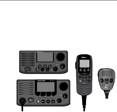
1.1 Ray218E and Ray55E Fixed Station VHF Radios
The Ray218E and Ray55E marine VHF radiotelephones are microprocessorcontrolled transceivers that provide reliable simplex (single frequency) and semiduplex (two frequency) communications. This handbook describes the physical and functional characteristics of these radios.
Ray55E |
Raymic |
|
(optional) |
Microphone
(standard)
Ray218E
 D9349-2
The Ray218E and Ray55E provide two-way communications on all International marine channels, pre-set private channels, and (if programmed) all US and Canadian marine and weather channels. Refer to the Frequency Tables in Appendix D, which list all marine VHF channels available in your radio. You should familiarize yourself with these tables to ensure proper channel usage.
1.2 Features
The Ray218E and Ray55E are designed and manufactured to provide ease of operation with excellent reliability. The Ray218E and Ray55E have many enhanced features, including:
•Waterproof to IPX-7 standard
•Anti-glare 1.9"(48mm) x 1.3" (32mm) LCD full dot matrix display
•3 soft keys for easy programming and menu selection
14 |
Ray218E and Ray55E Marine VHF Radios |
•Dedicated key for switching to Priority Channel 16
•Programmable Secondary Priority (PLUS) Channel key
•ATIS operation, if required
•Private Channels (if so licensed)
•All Scan, Memory Scan and 2 Priority Scan functions
•Dual/Tri Watch Monitor modes
•Enhanced GPS Position Data gives Latitude and Longitude to 1/10,000 of a minute plus Time, SOG and COG data from any NMEA input
•Automatically distinguishes between calls made to Ship or Coast Stations
•Low and High Voltage detection with alert
•Editable Channel Name
•10 Brightness and Contrast settings
•Optional Raymic Second Station Handset
•Optional external speakers for both transceiver and Raymic stations
Digital Selective Calling (DSC)
The Ray218E and Ray55E include equipment for Class “D” Digital Selective Calling (DSC). DSC protocol is a globally applied system used to send and receive digital calls. DSC uses a unique Maritime Mobile Service Identity (MMSI) number to direct DSC calls directly to your radio, much like a telephone number. Most importantly, DSC enables digital distress calls that automatically notify other ships and shore stations where you are and that you are in a distress situation.
Note: An MMSI ID number is required to operate the DSC equipment in this radio. You can request an MMSI number from the same agency that issues radio or Ship Radio licences in your area. Once obtained, you can program the MMSI number yourself one time only using the menu operation described in “My MMSI ID“ on page 96.
The Ray218E and Ray55E include the following DSC features:
•Separate receiver dedicated to handling DSC Calls on channel 70
•Position Request function sends GPS position data to or receives position data from other stations
•Phonebook for automatically making DSC calls
•Quick Call feature sends Individual Calls or Group Calls directly from the phonebook, just like the redial function on a telephone
•Five Group IDs for making DSC Calls only to stations in your group, such as a flotilla or fishing fleet
DSC functions are fully described in Chapter 5.
15
Chapter 2: Installation
2.1 Unpacking and Inspection
Use care when unpacking the unit from the shipping carton to prevent damage to the contents. It is also good practice to save the carton and the interior packing material in the event you must return the unit to the factory.
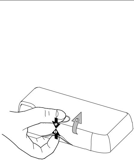
Removing the Sun Cover
The Sun Cover was designed to remain attached to the radio, even in rough seas.
To remove the Sun Cover:
1.Place your thumb in the dimple and push downward.
2.At the same time, pull up the lift tab with your index finger.
3.Pinch your fingers towards each other as you lift up.
D10233-1

16 |
Ray218E and Ray55E Marine VHF Radios |
Equipment Supplied
The following is a list of materials supplied with the Ray218E and Ray55E:
Part No |
Description |
E43033 |
Ray218E VHF Radio with removable microphone |
R49163 |
Sun Cover |
R49164 |
Mounting Bracket |
R49165 |
Bracket Knob for Ray218E/Ray55E/Ray49E |
R49172 |
Microphone |
R49166 |
Microphone Hanger for Ray218E/Ray55E/Ray49E |
R49241 |
Power Cord for Ray218E/Ray55E/Ray49E |
R49168 |
NMEA/Speaker/Hailer Cable |
81279 |
Handbook for Ray218E/Ray55E |
|
Screws (x5) for Mounting Bracket/Microphone Hanger |
|
Screw/Lock Washer (x1) for Grounding |
E43037 |
Ray55E VHF Radio with integral microphone |
R49170 |
Sun Cover |
R49169 |
Mounting Bracket |
R49165 |
Bracket Knob for Ray218E/Ray55E/Ray49E |
R49166 |
Microphone Hanger for Ray218E/Ray55E |
R49167 |
Power Cord for Ray218E/Ray55E/Ray49E |
81279 |
Handbook for Ray218E/Ray55E |
|
Screws (x5) for Mounting Bracket/Microphone Hanger |
|
Screw/Lock Washer (x1) for Grounding |
|
|
The following is a list of optional equipment:
Part No Description
A46052 Raymic Second Station for Ray218E/Ray55E
A46055 Raymic Extension Cable, 5m*
A46056 Raymic Extension Cable, 10m*
A46054 Microphone Relocation Kit for Ray218E/Ray55E
A46053 Rear Flush Mount Kit for Ray218E/Ray55E
A46060 Front Flush Mount Kit for Ray218E
E46006 10W External Speaker
M95435 Hailer Horn Speaker
* Maximum total Raymic extension cable length must not exceed 20 meters
Chapter 2: Installation |
17 |
2.2 Planning the Installation
Mount the transceiver to allow easy access from the location where the boat is normally navigated. Select a location that is non-metallic, dry, protected, wellventilated, and free from high operating temperatures and excessive vibration. Provide sufficient space behind the transceiver to allow for proper cable connections to the rear panel connectors. Locate the transceiver as near as possible to the power source yet as far apart as possible from any devices that may cause interference such as motors, generators, and other on board electronics. The radio should be protected from prolonged direct exposure to rain and salt spray.
The Ray218E/Ray55E is not designed to be mounted in engine compartments. Do not install the radio in a location where there may be flammable vapors (such as in an engine room or compartment, or in a fuel tank bay), water splash or spray from bilges or hatches, where it is at risk from physical damage from heavy items (such as hatch covers, tool boxes, etc.), or where it might be covered by other equipment. Locate the radio at least 1.5 meters from the antenna.
Safe Compass Distance is 1 meter for a common compass. To be sure, you should locate the radio as far as possible from the compass. Test your compass to verify proper operation while the radio is also operating.
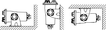
The Ray218E/Ray55E can be conveniently mounted on a chart table, bulkhead, overhead, or any other desired location. Refer to the following figure for typical mounting methods.
D9306-1 |
Table top mount |
Bulkhead mount |
Overhead mount |
The Ray218E/Ray55E may also be flush mounted using the optional A46053 Rear Flush Mount Kit, available from your Raymarine dealer. A Front Mount Kit (part number A 46060) is also available for the Ray218E. Instructions for installing the radio using the Flush Mount Kit are included with the kit.
18 |
Ray218E and Ray55E Marine VHF Radios |
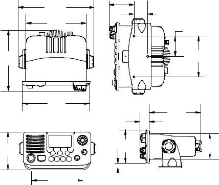
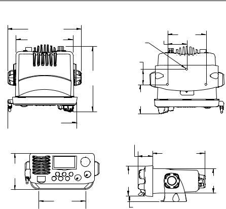
Ray218E Dimensions
222.5mm
(8.76")
176mm
(6.93")
179.3mm |
|
(7.06") |
top |
198mm
(7.79")
112.5mm
(4.43")
73mm |
|
(2.87") |
|
|
40mm |
|
(1.57") |
|
60mm |
|
(2.36") |
|
120mm |
bottom |
(4.72") |
|
|
151mm |
28.3mm |
(5.94") |
(1.12") |
|
97.5mm |
74mm |
(3.84") |
(2.91") |
150mm |
|
|
|
|
15mm |
|
|
|
|
|
|
|
|||
(5.91") |
|
|
|
|
|
(0.59") |
D9345-2 |
|
|
|
|
|
|||
|
|||||||
Chapter 2: Installation |
|
|
19 |
|
Ray55E Dimensions |
|
|
191mm (7.52") |
|
50mm |
100mm |
|
|
(3.94") |
|
148mm (5.83") |
|
(1.97") |
|
|
|
||
R2.6 |
|
|
|
|
|
|
|
|
40mm |
|
|
|
(1.57") |
|
|
|
174mm |
|
|
top |
(6.85") |
|
bottom |
|
|
||
|
75.3mm |
|
|
|
(2.96") |
|
|
 180mm (7.09")
|
38mm (1.50") |
|
|
136mm (5.35") |
|
93.8mm |
|
|
(3.69") |
80mm |
63.7mm |
|
||
|
(3.15") |
(2.51") |
122mm |
|
|
(4.80") |
13.8mm (0.54") |
D9344-2 |
|
20 |
Ray218E and Ray55E Marine VHF Radios |
2.3 Cable Connections
The radio has bullet connectors for power and cable connectors for attaching the optional Raymic or Microphone Relocation Kit. The remaining wires are for attaching NMEA, an optional external speaker, and an optional a hailer horn (Ray218E only). The Ray218E has a single cable with mating connectors for this purpose; the Ray55E has individual wire pairs. In either case, connect the wires as shown in the following table. Other connections are discussed in the ensuing sections.
Color |
Signal |
Connects to |
|
|
|
Gray |
NMEA IN + |
GPS |
Purple |
NMEA IN – |
|
|
|
|
Blue |
NMEA OUT + Chartplotter display unit (E Series, C Series, etc.) |
|
Brown |
NMEA OUT – |
|
|
|
|
Yellow |
SPEAKER + |
Optional remote speaker, Raymarine part no. E46006 |
Green |
SPEAKER – |
|
|
|
|
White |
HAILER + |
Optional horn speaker, Raymarine part no. M95435 |
Black |
HAILER – |
(Ray218E only) |
|
|
|
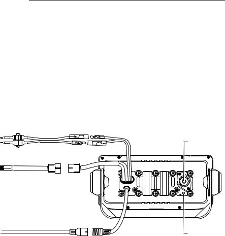
Make cable connections as shown in the following figures.
Ray218E Rear Connections
fuses |
Power |
|
|
|
Antenna |
|
NMEA/Speaker/Hailer |
D10332-2
RayMic /
Mic Relocation
Ground
Chapter 2: Installation |
21 |
|
Ray55E Rear Connections |
fuses |
Power |
|
|
|
Antenna |
NMEA / Speaker |
|
D10333-2
RayMic /
Mic Relocation
Ground
The ends of all wires are clipped at the factory so that no bare metal is exposed. You must strip back the insulation before installation. If you are not connecting a wire or set of wires (SPEAKER, for example), leave them insulated. If you have stripped back a wire that you will not be connecting, clip the bare wire down to the insulation.
Power
The red and black Power Cord provides connection to DC power. Slide the bullet connectors on the cord into their mates (with the same colored wire) on the rear of the radio. Connect the stripped wires on the Power Cord to the nearest primary source of the boat's DC power. A suitable source would be a circuit breaker on the power panel or a fuse block near the unit, rated at 10 amps. Connect the red wire to the positive terminal of the power source and the black wire to the negative (ground) of the power source. The red and black wires each contain an in-line fuse rated at 10A, 250V, slow-blow. If the fuses ever need to be replaced, be sure to use the same type and rating.
The power cord must be long enough to reach the DC power source. If additional wire length is required, the cable can be extended by adding more cable as necessary. However, for power cable runs longer than 15 feet, larger wire diameter size should be used to prevent voltage line loss. To ensure adequate current draw to the equipment, Raymarine recommends that you use lugs to connect the power cable to the DC supply and that the lug connections be both crimped and soldered.

22 |
Ray218E and Ray55E Marine VHF Radios |
The Ray218E/Ray55E is designed for a 12 volt (nominal) system. If battery voltage drops below 10.5 VDC, the  LOW icon appears on the LCD. Discontinue using the radio if a low voltage condition occurs as performance would be unreliable. If voltage increases to 15.8 VDC,
  HIGH appears. If voltage exceeds 18.5 VDC, the unit automatically shuts down to prevent damage.
Hailer Horn (Ray218E only)
Connect the white (+) wire and black (–) wire to the hailer horn observing polarity as it is marked on the speaker.
The HAILER – wire is the same color as the POWER – wire (black). Ensure that black HAILER – wire is NOT connected to ground or to the negative terminal of the boat’s battery.
Note: To avoid feedback, mount the horn so that it is facing away from the microphone and is located at least 3 meters (10 feet) from the microphone.
External Speaker
Connect the yellow (+) wire and green (–) wire from the radio to the same colored wires on the E46006 External Speaker. Be sure to insulate exposed bare ends.
Note: You can connect separate external speakers to the transceiver and to the optional Raymic second station.
Raymic / Mic Relocation
The radio has cable connectors for attaching either the optional A4605Raymic or the A46054 Microphone Relocation Kit for mounting the microphone in a remote location. Align the arrows on both connector ends and mate.
Raymic Extension cables are available from your Raymarine dealer in 5 meter (part no. A46055) and 10 meter (part no. A46056) lengths. Maximum total Raymic extension cable length must not exceed 20 meters.
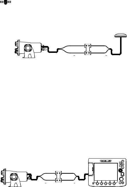
You can also install an optional E46006 external speaker to the Raymic. Connect the yellow (+) wire and green (–) wire from the E46006 External Speaker to the same colored wires emanating from the pigtail at the Raymic end of the extension cable. See the following figure.
Note: You can connect separate external speakers to the transceiver and to the optional Raymic second station.

Chapter 2: Installation |
23 |
||||||||||||||
|
Raymic |
External Speaker |
|||||||||||||
|
|
|
|
|
|
|
|
|
|
|
|
|
|
|
|
|
|
|
|
|
|
|
|
|
|
|
|
|
|
|
|
|
|
|
|
|
|
|
|
|
|
|
|
|
|
|
|
|
|
|
|
|
|
|
|
|
|
|
|
|
|
|
|
|
|
|
|
|
|
|
|
|
|
|
|
|
|
|
|
 D10325-2
Radio (rear)
Extension Cable
Raymic and External Speaker Connections
NMEA Data
The Ray218E/Ray55E accepts NMEA 0183 (V3.01) data from a position determining device (GPS) to provide the Latitude and Longitude position information. This information appears on the radio’s LCD display and is also transmitted during a DSC Distress Call. When a valid NMEA signal is detected, the GPS satellite indicator appears solid on the LCD. When no NMEA signal is detected, the GPS satellite indicator blinks.
When Distress Call and Position (lat/lon) information is received from other stations, your Ray218E/Ray55E also has the capability of outputting the vessel’s position to your chartplotter display unit (C Series, E Series, etc.) over the NMEA port so that it can be displayed on the screen. See “NMEA Output“ on page 61.
24 |
Ray218E and Ray55E Marine VHF Radios |
NMEA IN (from GPS)
Connect the NMEA OUT + and NMEA OUT – signals from the positioning device to the NMEA IN + (gray) and NMEA IN – (purple) wires, respectively, from the radio. An example of how to make the connections using a suitable connector block is shown in the following drawing. For specific instructions how to connect your particular GPS, please refer to the handbook that came with that device.
to Radio: |
from GPS: |
|
NMEA IN + (gray) |
NMEA OUT + |
|
NMEA IN (purple) |
NMEA OUT |
D9308-2 |
NMEA Alarm
When no valid position data is available, the NMEA alarm sounds (provided that the MMSI number has been programmed): the GPS satellite icon flashes and NO POS DATA is displayed on the dot matrix display. The alert tone sounds for 5 seconds or until you acknowledge it by pressing any key. The alarm repeats every four hours, as long as the condition exists.
If desired, you can manually enter time and position data using the GPS/Time Setup feature, as described on page 58. The alert repeats every four hours as long as no position information has been entered manually. If position data is entered manually but has not been updated during the previous 23.5 hours, all the position (lat/lon) fields are set to all 9’s, time field is set to all 8’s, and the display reverts to NO POS DATA.
NMEA OUT (to Chartplotter Display)
Connect the NMEA IN + and NMEA IN – signals from the chartplotter display to the NMEA OUT + (blue) and NMEA OUT – (brown) wires, respectively, from the radio. An example of how to make the connections using a suitable connector block is shown in the following drawing. For specific instructions how to connect your particular display, please refer to the handbook that came with that device.
from Radio: |
to Display: |
|
NMEA OUT + (blue) |
NMEA IN + |
|
NMEA OUT (brown) |
NMEA IN |
D9775-1 |
|
Chapter 2: Installation |
25 |
Antenna
Raymarine recommends that you install a VHF Marine band antenna with a minimum height of 8 ft. and gain of at least 6 dB.
The coaxial VHF antenna cable connects to the Ray218E/Ray55E antenna jack on the rear panel using a PL-259 VHF type connector. The antenna cable length can be critical to performance. If you are uncertain, contact a professional installer or call Raymarine Product Support. If a longer cable length is required, RG-8x (50 ohm) marine coaxial cable or equivalent cable can be used for runs up to a maximum of 50 feet. If the distance required is even greater, Raymarine recommends using low loss RG-213 or equivalent cable for the entire run to avoid excessive losses in power output.
If the antenna RF connector is likely to be exposed to the marine environment, a protective coating of silicon grease (Dow Corning DC-4 or similar) can be applied to the connector before connecting it to the radio. Any other extensions or adapters in the cable run should also be protected by grease and then wrapped with a waterproofing tape.
Antenna Mounting Suggestions
Mounting the VHF antenna properly is very important because it will directly affect the performance of your VHF radio. Use a VHF antenna designed for marine vessels. Since VHF transmission is essentially line-of-sight, mount the antenna at a location on the vessel that is free of obstruction to obtain maximum range.
If you must extend the length of the coaxial cable between the antenna and the radio, use a coaxial cable designed for the least amount of power loss over the entire cable length.
For optimal radio performance and minimal human exposure to radio frequency electromagnetic energy, make sure the antenna is:
•mounted as high as possible, but at least located at least 1.5 meters (5 feet) from the radio
•connected to the radio before transmitting
•located where it will be away from people
WARNING: Antenna Mounting and EME Exposure
Ensure that the antenna is mounted so that no one can enter the maximum permissible exposure radius for RF radiation. See the Safety Notice entitled “Antenna Mounting and EME Exposure“ on page 11.

26 |
Ray218E and Ray55E Marine VHF Radios |
Grounding
While special grounding is not required, it is good marine practice to properly ground all electronic equipment to the boat’s earth ground system. The Ray218E/ Ray55E can be connected to ground by installing the supplied screw and lock washer into the threaded hole labelled with the  icon, located on the transceiver’s rear panel, adjacent to the antenna jack. Then attach a #10 AWG wire from this screw to the nearest ship’s earth ground connection point.
CAUTION: Ground Connection
Do not connect this ground connection to the negative terminal of the battery.

27
Chapter 3: General Operations
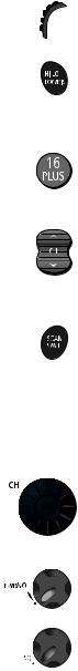
3.1 Keypad and Rotary Knobs
Several of the keys on the front panel of the transceiver serve multiple purposes. For the most part, the function indicated on the first line of the key is accessed by pressing that key for fewer than 3 seconds and then releasing it. The function indicated on the second line of the key is accessed by pressing and holding the key for greater than 3 seconds.
Ray218E
D9347-1
Ray55E
D9346-1
28 |
Ray218E and Ray55E Marine VHF Radios |
Microphone Keys
1. PTT
Press this Push-to-Talk key to transmit.
2. HILO / LOC DIST
Press and release to toggle the transmit power from HI to LO. Can also be used to select items in menu mode. Press and hold for to toggle between full receiver sensitivity (Distant mode) and attenuated receiver sensitivity (Local mode).
3. 16/PLUS
Use this key to switch to the priority channel or to change the value of the Secondary Priority (PLUS) Channel.
4. UP/DOWN
Use the arrow keys to change the active channel number. Press and hold for rapid channel changing. Can also be used to scroll through selections in menu and programming modes.
5. SCAN / SAVE
Press and release this key to access the Scan Mode menu, which is described on page 44. If Scan Mode is active, pressing this key terminates the scan. Press and hold for 3 seconds to enter a channel into the radio’s memory. This function is described in “Saving Channels to Memory“ on page 49.
Transceiver Controls
6. CH/OK
Rotate this knob to change the current channel number and to change values in Menu mode or during programming. Press in to enter values selected in Menu mode or during programming.
7. PWR/VOL
Use this knob to turn the radio ON and OFF and to set the volume.
8. SQ
Use this knob to set the squelch threshold, which cuts off the receiver when the signal is too weak for reception of anything but noise.

Chapter 3: General Operations |
29 |
9. Soft Keys
These multifunction keys change according to context, such as to navigate through menus or to make menu selections. Press to select the corresponding function as identified by the on-screen label.
Transceiver Push Keys
10. HAILER / INTCM (Ray218E only)
Press and release to access the hailer horn to make voice announcements or sound various fog horn tones. Press and hold for 3 seconds to use the intercom feature to communicate with a secondary station. Requires an optional Raymic second station.
This key is only available with the Ray218E.
11. MENU/DSC
Press and release this key to select Menu Mode, which is used to set up the radio. Menu operations are fully described in Chapter 4.
Press and hold for 3 seconds to enter DSC Call Mode, which is used for making DSC Calls and viewing the DSC Call Logs and the DSC Call Phonebook.
A Maritime Mobile Service Identity (MMSI) number is required to operate the DSC equipment in this radio. This number directs DSC calls directly to your radio, much like a telephone number. You can program the MMSI number yourself one time only using the operation described in “My MMSI ID“ on page 96. Otherwise, your Raymarine dealer can program or change the number for you.
Full details on DSC call operation are described in Chapter 5.
12. CLEAR
Press and release to terminate a function and return to the last-used channel. Press and hold for 3 seconds to select the Weather mode (if available).
13. 16/PLUS
Use this key to switch to the priority channel or to change the value of the Secondary Priority (PLUS) Channel.
14. DISTRESS
Push up the spring-loaded cover and press this key to make a DSC Distress Call. Instructions for making a Distress Call are described in Section 5.2.
30 |
Ray218E and Ray55E Marine VHF Radios |
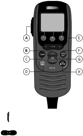
Optional Raymic Second Station
The optional Raymic Handset provides the Ray218E/Ray55E with a second station in a telephone handset design. The Raymic, which attaches to the handset connector on the rear of the radio, enables intercom capabilities with the transceiver from a remote portion of the vessel. Intercom functions are discussed on page 57.
 D9348-1
A. PTT
Press this Push-to-Talk key to transmit.
B. VOL/SQ
By default, these keys control earpiece speaker volume. Press the up arrow key to increase or the down arrow to decrease the volume.
Press and release the center key to activate the squelch threshold adjustment. Then, press up arrow key to increase or down arrow to decrease the squelch level.
Loading...