


 Loading...
ORDER NO.
CRT5389
MVH-X360BT/XINEW5
MVHRDS EDIA CENTER RECEIVER
-X360BT/XINEW5
MVH-X360BT/XINUC
MVH-X365BT/XINCS
MVH-X365BT/XINGS
PIONEER CORPORATION 1-1, Shin-ogura, Saiwai-ku, Kawasaki-shi, Kanagawa 212-0031, Japan PIONEER ELECTRONICS (USA) INC. P.O. Box 1760, Long Beach, CA 90801-1760, U.S.A.
PIONEER EUROPE NV Haven 1087, Keetberglaan 1, 9120 Melsele, Belgium
PIONEER ELECTRONICS ASIACENTRE PTE. LTD. 253 Alexandra Road, #04-01, Singapore 159936
 PIONEER CORPORATION 2013
K-ZZZ AUG. 2013 Printed in Japan

|
1 |
|
2 |
|
3 |
|
4 |
|
|
|
|
|
|
SAFETY INFORMATION
A CAUTION
This service manual is intended for qualified service technicians; it is not meant for the casual do-it-yourselfer. Qualified technicians have the necessary test equipment and tools, and have been trained to properly and safely repair complex products such as those covered by this manual.
Improperly performed repairs can adversely affect the safety and reliability of the product and may void the warranty. If you are not qualified to perform the repair of this product properly and safely, you should not risk trying to do so and refer the repair to a qualified service technician.
WARNING
This product may contain a chemical known to the State of California to cause cancer, or birth defects or other reproductive harm.
B Health & Safety Code Section 25249.6 - Proposition 65
Where in a manufacturer’s service documentation, for example in circuit diagrams or lists
of components, a symbol is used to indicate that a specific component shall be replaced only by the component specified in that documentation for safety reasons, the following symbol shall be used:
C
CAUTION
Danger of explosion if battery is incorrectly replaced.
Replaced only with the same or equivalent type recommended by the manufacturer.
Discord used batteries according to the manufacturer's instructions.
D
E
F
2 |
|
|
|
MVH-X360BT/XINEW5 |
|
|
|
|
|||
|
|
1 |
|
2 |
|
|
|
3 |
|
4 |
|
|
|
|
|
|
|
|
|
||||

|
5 |
|
|
6 |
|
7 |
|
8 |
|
|
|
|
|||||
|
CONTENTS |
|
|
|
|
|
||
|
SAFETY INFORMATION ..................................................................................................................................... |
|
|
|
2 |
|||
|
1. SERVICE PRECAUTIONS................................................................................................................................ |
|
|
|
4 |
|||
|
1.1 SERVICE PRECAUTIONS ......................................................................................................................... |
|
|
|
4 |
|||
|
1.2 NOTES ON SOLDERING........................................................................................................................... |
|
|
|
4 |
|||
|
2. SPECIFICATIONS............................................................................................................................................. |
|
|
|
5 |
|||
|
2.1 SPECIFICATIONS ...................................................................................................................................... |
|
|
|
5 |
|||
|
2.2 DISC/CONTENT FORMAT......................................................................................................................... |
|
|
|
8 |
|||
|
3. BASIC ITEMS FOR SERVICE .......................................................................................................................... |
|
|
|
9 |
|||
|
3.1 CHECK POINTS AFTER SERVICING ....................................................................................................... |
|
|
|
9 |
|||
|
3.2 PCB LOCATIONS....................................................................................................................................... |
|
|
|
9 |
|||
|
4. BLOCK DIAGRAM .......................................................................................................................................... |
|
|
|
10 |
|||
|
5. DIAGNOSIS .................................................................................................................................................... |
|
|
|
12 |
|||
|
5.1 OPERATIONAL FLOWCHART................................................................................................................. |
|
|
|
12 |
|||
|
5.2 ERROR CODE LIST................................................................................................................................. |
|
|
|
13 |
|||
|
5.3 CONNECTOR FUNCTION DESCRIPTION ............................................................................................. |
|
|
14 |
||||
|
6. SERVICE MODE............................................................................................................................................. |
|
|
|
15 |
|||
|
6.1 DISPLAY TEST MODE 1.......................................................................................................................... |
|
|
|
15 |
|||
|
6.2 DISPLAY TEST MODE 2.......................................................................................................................... |
|
|
|
16 |
|||
|
6.3 SOFTWARE VERSION UP METHOD...................................................................................................... |
|
|
|
17 |
|||
|
7. DISASSEMBLY ............................................................................................................................................... |
|
|
|
18 |
|||
|
8. EACH SETTING AND ADJUSTMENT............................................................................................................ |
|
|
|
21 |
|||
|
8.1 PCL OUTPUT CONFIRMATION .............................................................................................................. |
|
|
|
21 |
|||
|
9. EXPLODED VIEWS AND PARTS LIST .......................................................................................................... |
|
|
|
22 |
|||
|
9.1 PACKING.................................................................................................................................................. |
|
|
|
22 |
|||
|
9.2 EXTERIOR ............................................................................................................................................... |
|
|
|
24 |
|||
|
10. SCHEMATIC DIAGRAM................................................................................................................................ |
|
|
|
26 |
|||
|
10.1 TUNER AMP UNIT (GUIDE PAGE)........................................................................................................ |
|
|
|
26 |
|||
|
10.2 KEYBOARD UNIT .................................................................................................................................. |
|
|
|
32 |
|||
|
10.3 BT UNIT.................................................................................................................................................. |
|
|
|
34 |
|||
|
11. PCB CONNECTION DIAGRAM .................................................................................................................... |
|
|
|
36 |
|||
|
11.1 TUNER AMP UNIT ................................................................................................................................. |
|
|
|
36 |
|||
|
11.2 KEYBOARD UNIT................................................................................................................................... |
|
|
|
40 |
|||
|
11.3 BT UNIT .................................................................................................................................................. |
|
|
|
41 |
|||
|
12. ELECTRICAL PARTS LIST........................................................................................................................... |
|
|
|
42 |
|||
A
B
C
D
E
F
|
|
|
|
MVH-X360BT/XINEW5 |
|
|
|
3 |
|
||
|
5 |
|
6 |
|
|
7 |
|
8 |
|
|
|
|
|
|
|
|
|
||||||

|
1 |
|
2 |
|
3 |
|
4 |
|
|
|
|
|
|
1. SERVICE PRECAUTIONS
1.1 SERVICE PRECAUTIONS
A
1.You should conform to the regulations governing the product (safety, radio and noise, and other regulations), and should keep the safety during servicing by following the safety instructions described in this manual.
2.Before disassembling the unit, be sure to turn off the power. Unplugging and plugging the connectors during power-on mode may damage the ICs inside the unit.
3.Be careful in handling ICs. Some ICs such as MOS type are so fragile that they can be damaged by electrostatic induction.
4.Notes about installation and pin number description of Power IC (IC301: PA2032A) The Power IC, PA2032A used on tha Tuner Amp Unit is a 25 pin IC.
The same PCB of the Tuner Amp Unit is used for other models that use a 27 pin IC, too.
BSo, the PCB has lands for a 27 pin IC.
When you replace the Power IC, install the Power IC onto 25 pins (2- 26 pin) located in the center of 27 pins for IC301.
Therefore, when you check the Power IC on the block diagram, the schematic diagram and the PCB connection diagram, you have to pay attention as follows.
|
BLOCK DIAGRAM |
SCHEMATIC DIAGRAM |
|
|
12 (11) |
|
13 (12) |
|
10 (9) |
|
8 (7) |
|
6 (5) |
C |
4 (3) |
|
23 (22) |
|
26 (25) |
|
H-SW |
|
2 (1) |
|
OFF.DET |
The pin number is a number on the PCB (silk printing).
The number in parentheses means the pin number of IC itself.
D
No connection
1
2
3
4
5
6
7
8
9
10
11
12
13
14
15
16
17
18
19
20
21
22
23
24
25
No connection
The pin number of left side is a number on the PCB (silk printing).
The pin number of right side (in the IC frame) means the pin number of IC itself.
|
1.2 NOTES ON SOLDERING |
|
|
|
For environmental protection, lead-free solder is used on the printed circuit boards mounted in this unit. |
|
Be sure to use lead-free solder and a soldering iron that can meet specifications for use with lead-free solders for repairs |
|
accompanied by reworking of soldering. |
E |
Compared with conventional eutectic solders, lead-free solders have higher melting points, by approximately 40 C. |
|
Therefore, for lead-free soldering, the tip temperature of a soldering iron must be set to around 373 C in general, although |
|
the temperature depends on the heat capacity of the PC board on which reworking is required and the weight of the tip of |
|
the soldering iron. |
|
Compared with eutectic solders, lead-free solders have higher bond strengths but slower wetting times and higher melting |
|
temperatures (hard to melt/easy to harden). |
|
|
|
The following lead-free solders are available as service parts: |
|
Parts numbers of lead-free solder: |
|
GYP1006 1.0 in dia. |
|
GYP1007 0.6 in dia. |
F |
GYP1008 0.3 in dia. |
|
4 |
|
|
|
MVH-X360BT/XINEW5 |
|
|
|
|
|||
|
|
1 |
|
2 |
|
|
|
3 |
|
4 |
|
|
|
|
|
|
|
|
|
||||

|
5 |
|
6 |
|
|
|
|
2. SPECIFICATIONS
2.1 SPECIFICATIONS
 MVH-X360BT/XINEW5
General
Power source ................... |
14.4 V DC (10.8 V to 15.1 V al- |
|
lowable) |
Grounding system ............ |
Negative type |
Maximum current consumption |
|
................................... |
10.0 A |
Backup current.................. |
4.0 mA or less |
Dimensions (W × H × D): |
|
DIN |
|
Chassis ............................ |
178 mm × 50 mm × 165 mm |
Nose ................................ |
188 mm × 58 mm × 15 mm |
D |
|
Chassis ............................ |
178 mm × 50 mm × 165 mm |
Nose ................................ |
170 mm × 46 mm × 16 mm |
Weight ............................. |
0.7 kg |
Audio
Maximum power output ... |
50 W × 4 |
|
70 W × 1/2 Ω (for subwoofer) |
Continuous power output |
|
................................... |
22 W × 4 (50 Hz to 15 000 Hz, |
|
5 % THD, 4 Ωl oad, both chan- |
|
nels driven) |
Load impedance .............. |
4 Ω (4 Ω to 8 Ω allowable) |
Preout maximum output level |
|
................................... |
2.0 V |
Loudness contour ............ |
+10 dB (100 Hz), +6.5 dB |
|
(10 kHz) (volume:–30 dB) |
Equalizer (5-Band Graphic Equalizer): |
|
Frequency ........................ |
80 Hz/250 Hz/800 Hz/2.5 kHz/ |
|
8 kHz |
Equalization range ........... |
±12 dB (2 dB step) |
Subwoofer (mono): |
|
Frequency ........................ |
50 Hz/63 Hz/80 Hz/100 Hz/ |
|
125 Hz/160 Hz/200 Hz |
Slope ............................... |
–12 dB/oct,–24 dB/oct |
Gain ................................ |
+6 dB to –24 dB |
Phase .............................. |
Normal/Reverse |
7 |
|
8 |
|
WMA decoding format ..... |
Ver. 7, 7.1, 8, 9, 10, 11, 12 (2 ch |
|
audio) |
|
(Windows Media Player) |
WAV signal format ........... |
Linear PCM & MS ADPCM |
|
(Non-compressed) |
FM tuner
Frequency range .............. |
87.5 MHz to 108.0 MHz |
Usable sensitivity ............. |
9 dBf (0.8 µV/75 Ω, mono, S/N: |
|
30 dB) |
Signal-to-noise ratio ......... |
72 dB (IEC-A network) |
MW tuner
Frequency range .............. |
531 kHz to 1 602 kHz |
Usable sensitivity ............. |
25 µV (S/N: 20 dB) |
Signal-to-noise ratio ......... |
62 dB (IEC-A network) |
LW tuner
Frequency range .............. |
153 kHz to 281 kHz |
Usable sensitivity ............. |
28 µV (S/N: 20 dB) |
Signal-to-noise ratio ......... |
62 dB (IEC-A network) |
Bluetooth
Version ............................ |
Bluetooth 3.0 certified |
Output power ................... |
+4 dBm Maximum |
|
(Power class 2) |
Note
Specifications and the design are subject to modifications without notice.
A
B
C
D
USB
USB standard specification |
|
|
................................... |
USB 2.0 full speed |
|
Maximum current supply |
|
|
................................... |
1 A |
|
|
|
|
USB Class |
MSC (Mass Storage Class) |
|
|
||
File system....................... |
FAT12, FAT16, FAT32 |
|
MP3 decoding format ...... |
MPEG-1 & 2 Audio Layer 3 |
|
E
F
|
|
|
|
MVH-X360BT/XINEW5 |
|
|
|
5 |
|
||
|
5 |
|
6 |
|
|
7 |
|
8 |
|
|
|
|
|
|
|
|
|
||||||

|
1 |
|
2 |
|
|
|
|
A  MVH-X360BT/XINUC
General
|
Power source ................... |
14.4 V DC (10.8 V to 15.1 V al- |
|
|
|
lowable) |
|
|
Grounding system ............ |
Negative type |
|
|
Maximum current consumption |
||
|
|||
|
................................... |
10.0 A |
|
|
Backup current.................. |
4.0 mA or less |
|
|
Dimensions (W × H × D): |
|
|
|
DIN |
|
|
|
Chassis ............................ |
178 mm × 50 mm × 165 mm |
|
B |
|
(7 in. × 2 in. × 6-1/2 in.) |
|
Nose |
188 mm × 58 mm × 16 mm |
||
|
|||
|
|
(7-3/8 in.× 2-1/4 in.× 5/8 in.) |
|
|
D |
|
|
|
Chassis ............................ |
178 mm × 50 mm × 165 mm |
|
|
|
(7 in.× 2 in.× 6-1/2 in.) |
|
|
Nose ................................ |
170 mm × 46 mm × 16 mm |
|
|
|
(6-3/4 in.× 1-3/4 in.× 5/8 in.) |
|
|
|
||
|
.............................Weight |
0.7 kg (1.5 lbs) |
|
Audio
|
|
Maximum power output ... |
50 W × 4 |
|
|
|
|
70 W × 1/2 Ω (for subwoofer) |
|
C |
Continuous power output |
|
||
|
|
................................... |
22 W × 4 (50 Hz to 15 000 Hz, |
|
|
|
|
5 % THD, 4 Ω load, both chan- |
|
|
|
|
nels driven) |
|
|
|
Load impedance .............. |
4 Ω (4 Ω to 8 Ω allowable) |
|
|
|
Preout maximum output level |
||
|
|
................................... |
2.0 V |
|
|
|
Loudness contour |
+10 dB (100 Hz), +6.5 dB |
|
|
|
|||
|
|
|
(10 kHz) (volume:–30 dB) |
|
|
|
Equalizer (5-Band Graphic Equalizer): |
||
|
|
Frequency ........................ |
80 Hz/250 Hz/800 Hz/2.5 kHz/ |
|
|
|
|
8 kHz |
|
|
|
Equalization range ........... |
±12 dB (2 dB step) |
|
D |
Subwoofer (mono): |
|
||
Frequency |
50 Hz/63 Hz/80 Hz/100 Hz/ |
|||
|
|
|||
|
|
|
125 Hz/160 Hz/200 Hz |
|
|
|
Slope ............................... |
–12 dB/oct, –24 dB/oct |
|
|
|
Gain ................................ |
+6 dB to –24 dB |
|
|
|
Phase .............................. |
Normal/Reverse |
|
|
|
|
|
|
|
|
|
|
|
USB
USB standard specification
................................... USB 2.0 full speed
E
F
3 |
|
4 |
|
|
|
Maximum current supply |
|
................................... |
1 A |
USB Class ....................... |
MSC (Mass Storage Class) |
File system....................... |
FAT12, FAT16, FAT32 |
MP3 decoding format ...... |
MPEG-1 & 2 Audio Layer 3 |
WMA decoding format ..... |
Ver. 7, 7.1, 8, 9, 10, 11, 12 (2 ch |
|
audio) |
|
(Windows Media Player) |
WAV signal format ........... |
Linear PCM & MS ADPCM |
|
(Non-compressed) |
FM tuner
Frequency range .............. |
87.9 MHz to 107.9 MHz |
Usable sensitivity ............. |
9 dBf (0.8 µV/75 Ω , mono, S/N: |
|
30 dB) |
Signal-to-noise ratio ......... |
72 dB (IHF-A network) |
AM tuner
Frequency range .............. |
530 kHz to 1 710 kHz |
Usable sensitivity ............. |
25 µV (S/N: 20 dB) |
Signal-to-noise ratio ......... |
62 dB (IHF-A network) |
Bluetooth
Version ............................ |
Bluetooth 3.0 certified |
Output power ................... |
+4 dBm Maximum |
|
(Power class 2) |
CEA2006 Specifications
Power output |
................... 14 W RMS × 4 Channels (4 Ω |
|
and 1 % THD+N) |
S/N ratio .......................... |
91 dBA (reference: 1 W into |
|
4 Ω) |
Note
Specifications and the design are subject to modifications without notice.
6 |
|
|
|
MVH-X360BT/XINEW5 |
|
|
|
|
|||
|
|
1 |
|
2 |
|
|
|
3 |
|
4 |
|
|
|
|
|
|
|
|
|
||||

|
5 |
|
6 |
|
|
|
|
 MVH-X365BT/XINCS
General
Rated power source ......... |
14.4 V DC |
|
(allowable voltage range: |
|
12.0 V to 14.4 V DC) |
Grounding system ............ |
Negative type |
Maximum current consumption |
|
................................... |
10.0 A |
Backup current.................. |
4.0 mA or less |
Dimensions (W × H × D): |
|
DIN |
|
Chassis ............................ |
178 mm × 50 mm × 165 mm |
Nose ................................ |
188 mm × 58 mm × 15 mm |
D |
|
Chassis ............................ |
178 mm × 50 mm × 165 mm |
Nose ................................ |
170 mm × 46 mm × 16 mm |
Weight ............................. |
0.7 kg |
Audio
Maximum power output ... |
50 W × 4 |
|
70 W × 1/2 Ω (for subwoofer) |
Continuous power output |
|
................................... |
22 W × 4 (50 Hz to 15 000 Hz, |
|
5 % THD, 4 Ω load, both chan- |
|
nels driven) |
Load impedance .............. |
4 Ω(4 Ω to 8 Ω allowable) |
Preout maximum output level |
|
................................... |
2.0 V |
Loudness contour ............ |
+10 dB(100 Hz), +6.5 dB |
|
(10 kHz) (volume:–30 dB) |
Equalizer (5-Band Graphic Equalizer): |
|
Frequency ........................ |
80 Hz/250 Hz/800 Hz/2.5 kHz/ |
|
8 kHz |
Equalization range ........... |
±12 dB (2 dBstep) |
Subwoofer (mono): |
|
Frequency ........................ |
50 Hz/63 Hz/80 Hz/100 Hz/ |
|
125 Hz/160 Hz/200 Hz |
Slope ............................... |
–12 dB/oct, –24 dB/oct |
Gain ................................ |
+6 dB to –24 dB |
Phase .............................. |
Normal/Reverse |
7 |
|
8 |
|
MP3 decoding format ...... |
MPEG-1 & 2 Audio Layer 3 |
WMA decoding format ..... |
Ver. 7, 7.1, 8, 9, 10, 11, 12 (2 ch |
|
audio) |
|
(Windows Media Player) |
WAV signal format ........... |
Linear PCM & MS ADPCM |
|
(Non-compressed) |
FM tuner
Frequency range .............. |
87.5 MHz to 108.0 MHz |
Usable sensitivity ............. |
9 dBf(0.8 µV/75 Ω, mono, S/N: |
|
30 dB) |
Signal-to-noise ratio ......... |
72 dB (IEC-A network) |
AM tuner
Frequency range .............. |
531 kHz to 1 602 kHz (9 kHz) |
|
530 kHz to 1 640 kHz (10 kHz) |
Usable sensitivity ............. |
25 µV (S/N: 20 dB) |
Signal-to-noise ratio ......... |
62 dB (IEC-A network) |
Bluetooth
Version ............................ |
Bluetooth 3.0 certified |
Output power ................... |
+4 dBm Maximum |
|
(Power class 2) |
Note
Specifications and the design are subject to modifications without notice.
A
B
C
D
USB
USB standard specification |
|
|
Maximum...................................current supply |
USB 2.0 full speed |
|
|
||
1 A |
|
|
|
||
................................... |
|
|
USB Class ....................... |
MSC(Mass Storage Class) |
|
File system....................... |
FAT12, FAT16, FAT32 |
|
E
F
|
|
|
|
MVH-X360BT/XINEW5 |
|
|
|
7 |
|
||
|
5 |
|
6 |
|
|
7 |
|
8 |
|
|
|
|
|
|
|
|
|
||||||

1  2
2
 MVH-X365BT/XINGS
General
A |
Rated power source ......... |
14.4 V DC |
|
|
(allowable voltage range: |
||
|
|
||
|
|
12.0 V to 14.4 V DC) |
|
|
Grounding system ............ |
Negative type |
|
|
Maximum current consumption |
||
|
................................... |
10.0 A |
|
|
Backup current.................. |
4.0 mA or less |
|
|
Dimensions (W × H × D): |
|
|
|
|
||
|
DIN |
|
|
|
Chassis ............................ |
178 mm × 50 mm × 165 mm |
|
|
Nose ................................ |
188 mm × 58 mm × 15 mm |
|
|
D |
|
|
|
Chassis ............................ |
178 mm × 50 mm × 165 mm |
|
B |
Nose ................................ |
170 mm × 46 mm × 16 mm |
|
Weight |
0.7 kg |
||
|
|||
Audio
|
|
Maximum power output ... |
50 W × 4 |
|
|
|
70 W × 1/2 Ω (for subwoofer) |
|
|
Continuous power output |
22 W × 4 (50 Hz to 15 000 Hz, |
|
|
|
|
|
|
................................... |
|
|
|
|
5 % THD, 4 Ω load, both chan- |
|
|
|
nels driven) |
|
|
Load impedance .............. |
4 Ω (4 Ω to 8 Ω allowable) |
|
|
Preout maximum output level |
|
|
|
................................... |
2.0 V |
C |
Loudness contour ............ |
+10 dB (100 Hz), +6.5 dB |
|
|
|
|
(10 kHz) (volume:–30 dB) |
|
|
Equalizer (5-Band Graphic Equalizer): |
|
|
|
Frequency ........................ |
80 Hz/250 Hz/800 Hz/2.5 kHz/ |
|
|
|
8 kHz |
|
|
Equalization range ........... |
±12 dB (2 dB step) |
|
|
Subwoofer (mono): |
|
|
|
........................Frequency |
50 Hz/63 Hz/80 Hz/100 Hz/ |
|
|
||
|
|
|
125 Hz/160 Hz/200 Hz |
|
|
Slope ............................... |
–12 dB/oct, –24 dB/oct |
|
|
Gain ................................ |
+6 dB to –24 dB |
|
|
Phase .............................. |
Normal/Reverse |
D |
USB |
|
|
|
|
|
|
|
|
USB standard specification |
|
|
|
................................... |
USB 2.0 full speed |
|
|
Maximum current supply |
|
|
|
................................... |
1 A |
|
|
USB Class ....................... |
MSC (Mass Storage Class) |
|
|
File system |
FAT12, FAT16, FAT32 |
|
|
||
E 2.2 DISC/CONTENT FORMAT
|
3 |
|
4 |
|
|
|
|
MP3 decoding format ...... |
MPEG-1 & 2 Audio Layer 3 |
WMA decoding format ..... |
Ver. 7, 7.1, 8, 9, 10, 11, 12 (2 ch |
|
audio) |
|
(Windows Media Player) |
WAV signal format ........... |
Linear PCM & MS ADPCM |
|
(Non-compressed) |
FM tuner
Frequency range .............. |
87.5 MHz to 108.0 MHz |
Usable sensitivity ............. |
9 dBf (0.8 µV/75 Ω , mono, S/N: |
|
30 dB) |
Signal-to-noise ratio ......... |
72 dB (IEC-A network) |
MW tuner/AM tuner
Frequency range .............. |
531 kHz to 1 602 kHz (9 kHz) |
|
530 kHz to 1 640 kHz (10 kHz) |
Usable sensitivity ............. |
25 µV (S/N: 20 dB) |
Signal-to-noise ratio ......... |
62 dB (IEC-A network) |
SW tuner
Frequency range .............. |
2 300 kHz to 7 735 kHz |
|
(2 300 kHz to 2 495 kHz, |
|
2 940 kHz to 4 215 kHz, |
|
4 540 kHz to 5 175 kHz, |
|
5 820 kHz to 6 455 kHz, |
|
7 100 kHz to 7 735 kHz) |
|
9 500 kHz to 21 975 kHz |
|
(9 500 kHz to 10 135 kHz, |
|
11 580 kHz to 12 215 kHz, |
|
13 570 kHz to 13 870 kHz, |
|
15 100 kHz to 15 735 kHz, |
|
17 500 kHz to 17 985 kHz, |
|
18 015 kHz to 18 135 kHz, |
|
21 340 kHz to 21 975 kHz) |
Usable sensitivity ............. |
28 µV (S/N: 20 dB) |
Signal-to-noise ratio ......... |
62 dB (IEC-A network) |
Bluetooth
Version ............................ |
Bluetooth 3.0 certified |
Output power ................... |
+4 dBm Maximum |
|
(Power class 2) |
Note
Specifications and the design are subject to modifications without notice.
The Bluetooth word mark and logos are registered trademarks owned by Bluetooth SIG, Inc. and any use of such marks by PIONEER CORPORATION is under license.
Other trademarks and trade names are those of their respective owners.
F
8 |
|
|
|
MVH-X360BT/XINEW5 |
|
|
|
|
|||
|
|
1 |
|
2 |
|
|
|
3 |
|
4 |
|
|
|
|
|
|
|
|
|
||||
|
5 |
|
6 |
|
7 |
|
8 |
|
|
|
|
3. BASIC ITEMS FOR SERVICE
3.1 CHECK POINTS AFTER SERVICING
To keep the product quality after servicing, please confirm following check points.
No. |
|
Procedures |
Item to be confirmed |
1 |
|
Confirm whether the customer complain has |
The customer complain must not be |
|
|
been solved. |
reappeared. |
|
|
If the customer complain occurs with the |
Display, audio and operations must be |
|
|
specific media, use it for the operation check. |
normal. |
|
|
|
|
2 |
FM/AM tuner |
Check FM/AM tuner action. |
Display, audio and operations must be |
|
|
(Seek, Preset) |
normal. |
|
|
Switch band to check both FM and AM. |
|
|
|
|
|
3 |
|
Appearance check |
No scratches or dirt on its appearance after |
|
|
|
receiving it for service. |
See the table below for the items to be checked regarding audio:
Item to be checked regarding audio
Distortion
Noise
Volume too low
Volume too high
Volume fluctuating
Sound interrupted
A
B
C
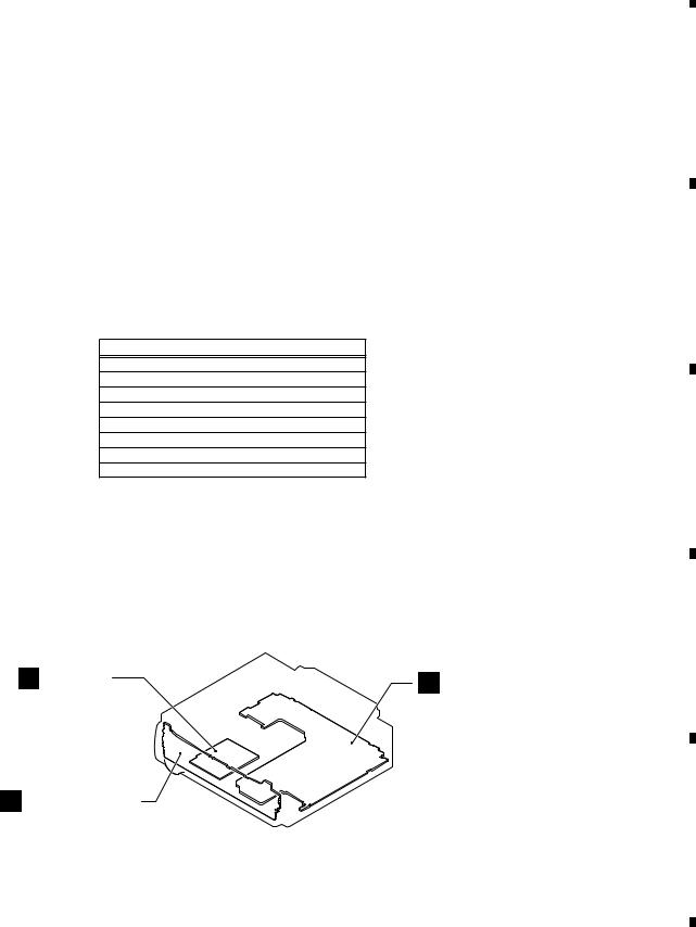
3.2 PCB LOCATIONS
C BT Unit
B Keyboard Unit
A Tuner Amp Unit
A:MVH-X360BT/XINEW5 B:MVH-X360BT/XINUC C:MVH-X365BT/XINCS D:MVH-X365BT/XINGS
Unit Number |
: QWM3665(A) |
Unit Number |
: QWM3664(B) |
Unit Number |
: QWM3666(C) |
Unit Number |
: QWM3667(D) |
Unit Name |
: Tuner Amp Unit |
Unit Number |
: (A) |
Unit Number |
: (B,C,D) |
Unit Name |
: Keyboard Unit |
Unit Number |
: QWM3750 |
Unit Name |
: BT Unit |
D
E
F
|
|
|
|
MVH-X360BT/XINEW5 |
|
|
|
9 |
|
||
|
5 |
|
6 |
|
|
7 |
|
8 |
|
|
|
|
|
|
|
|
|
||||||

1 |
|
|
|
2 |
|
|
|
3 |
|
|
|
|
|
4 |
|
4. BLOCK DIAGRAM |
|
|
|
|
|
|
|
|
|
|
|
|
|||
A |
|
A TUNER AMP UNIT |
|
|
|
|
|
|
|
|
|
|
|||
|
ANTENNA |
|
|
|
|
|
|
|
|
|
|
||||
|
|
JA401 |
|
|
|
|
|
|
|
|
|
|
|
|
|
|
FM/AM |
|
|
|
|
|
|
|
|
|
|
|
|
|
|
|
|
1 |
5 |
FMMIXIN1 |
|
|
|
|
|
|
|
|
|
|
|
|
|
|
|
|
|
|
|
|
|
|
|
|
|||
|
|
2,3 |
16 |
PINDIN |
|
|
|
|
|
|
|
|
|
|
|
|
|
|
|
18 |
LNAIN |
DACOUTL |
57 |
|
|
|
|
|
|
|
|
|
|
|
|
|
FM/AM TUNER |
|
|
|
|
|
|
|
|
|
|
|
|
|
|
|
IC401 |
|
|
|
|
|
|
|
|
|
|
|
|
|
|
|
TDA7706 |
|
|
|
|
|
|
|
RESET |
|
|
|
|
|
|
|
|
|
|
|
|
|
|
|
IC671 |
|
|
|
|
|
|
|
|
|
|
|
|
|
|
S-80827CNMC-B8M |
|
||
|
|
|
|
|
|
I2CSCL |
34 |
93 |
TUN_SCL |
RES |
39 |
1 |
OUT |
VDD 2 |
VDD3.3V |
|
|
|
|
|
|
I2CSDA |
33 |
94 |
TUN_SDA |
|
|
|
|
|
|
|
|
|
|
|
|
31 |
88 |
|
|
|
|
|
|
||
B |
|
|
|
|
|
RSTN |
TUNRES |
|
|
|
|
|
|
||
|
|
|
|
|
|
|
|
|
|
|
|
|
|
|
|
|
|
JA892 |
|
|
|
|
|
|
|
|
|
|
FLASH ROM |
|
|
WIRED REMOTE |
|
3 |
KEYD |
|
|
|
|
105 |
|
|
|
|
|
|
|
|
|
|
|
|
KEYD |
|
|
|
|
IC681 |
|
||||
|
2 |
KEYAD |
|
|
|
|
56 |
|
|
|
|
A |
B :PEB102A8 |
||
|
|
|
|
|
|
KEYAD |
|
|
|
C D :PEB096A8 |
|||||
|
|
1 GND |
|
|
|
|
|
|
|
|
|
|
|
|
|
RMIC |
|
6 |
|
|
|
|
|
|
SYSTEM MICRO |
|
|
|
|
|
|
|
4 |
MIC1N |
|
|
|
|
|
|
|
|
|
|
|||
|
|
|
|
|
|
IC601 |
|
|
|
|
|
|
|||
|
|
5 |
MIC1P |
|
|
|
|
|
COMPUTER |
|
|
|
|
|
|
|
|
|
|
|
|
|
|
|
(1/2) |
|
|
|
|
|
|
|
|
|
|
|
|
|
|
|
R5S726A0D216FP |
|
|
|
|
|
|
|
|
|
|
|
|
|
|
|
|
|
|
|
|
|
|
|
|
|
|
|
|
|
|
|
|
|
|
|
|
|
|
8 |
|
Q531 |
|
|
|
|
|
|
|
|
|
|
|
|
|
|
A :MVH-X360BT/XINEW5 |
|
|
|
|
|||||||||||||||||||||||||||
|
|
|
|
|
|
|
|
|
|
|
|
|
|
|
|
|
|
|
|
|
|
|
|
|
|
|
|
|
|
|
VCC |
|
|
|
|
|
|
|
VDD3.3V |
|
|
|
|
|
|
|
|
|
|
|
|
|
|
|
|
|
|
|||||||||||||||||||||||
|
|
|
|
|
|
|
|
|
|
|
|
|
|
|
|
|
|
|
|
|
|
|
|
|
|
|
|
|
|
|
|
|
|
|
|
|
|
|
|
|
|
|
|
|
|
|
|
|
|
|
|
|
|
|
|
|
||||||||||||||||||||||||
|
|
|
|
|
|
|
|
|
|
|
|
|
|
|
|
|
|
|
|
|
|
|
|
|
|
|
|
|
|
|
iPod CP |
|
|
|
|
|
|
|
|
|
|
|
|
|
|
|
|
|
|
|
|
|
|
|
|
|
B :MVH-X360BT/XINUC |
|
|
|
|
|||||||||||||||||||
C |
|
|
|
|
|
|
|
|
|
|
|
|
|
|
|
|
|
|
|
|
|
|
|
|
|
|
|
|
|
|
|
|
|
|
|
|
|
|
|
|
25 |
|
|
|
|
|
|
|
|
|
|
|
|
|
C :MVH-X365BT/XINCS |
|
|
|
|
|||||||||||||||||||||
|
|
|
|
|
|
|
|
|
|
|
|
|
|
|
|
|
|
|
|
|
|
|
|
|
|
|
|
|
IC531 |
|
|
|
|
|
|
|
|
|
|
|
|
|
CPPWR |
|
|
|
|
|
|
|
|
|
|
|
||||||||||||||||||||||||||
|
|
|
|
|
|
|
|
|
|
|
|
|
|
|
|
|
|
|
|
|
|
|
|
|
|
|
|
|
|
|
337S3959 |
|
|
|
|
|
|
|
|
|
|
|
|
|
|
|
|
|
|
|
|
|
|
|
|
|
D :MVH-X365BT/XINGS |
|
|
|
|
|||||||||||||||||||
|
|
|
|
|
|
|
|
|
|
|
|
|
|
|
|
|
|
|
|
|
|
|
|
|
|
|
|
|
|
|
|
6 |
|
|
|
|
|
|
|
|
|
|
91 |
|
|
|
|
|
|
|
|
|
|
|
|
|
|
|
|
|
||||||||||||||||||||
|
|
|
|
|
|
|
|
|
|
|
|
|
|
|
|
|
|
|
|
|
|
|
|
|
|
|
|
|
|
|
SCL |
|
|
|
|
|
|
|
|
|
|
|
|
CP_SCL |
|
|
|
|
|
|
|
|
|
|
|
|
|
|
|
|
|
|
|
|
|
|
|
|
|
|
|
|
|
|
||||||
|
|
|
|
|
|
|
|
|
|
|
|
|
|
|
|
|
|
|
|
|
|
|
|
|
|
|
|
|
2 |
|
|
|
|
|
|
|
|
|
|
92 |
|
|
|
|
|
|
|
|
|
|
|
|
|
|
|
|
|
|
|
|
|
|
|
|
|
|
|
|
|
|
|
|||||||||
|
|
|
|
|
|
|
|
|
|
|
|
|
|
|
|
|
|
|
|
|
|
|
|
|
|
|
|
|
|
|
SDA |
|
|
|
|
|
|
|
|
|
|
|
|
CP_SDA |
|
|
|
|
|
|
|
|
|
|
|
|
|
|
|
|
|
|
|
|
|
|
|
|
|
|
|
|
|
|
||||||
|
|
|
|
C |
BT UNIT |
|
|
|
|
|
|
|
|
|
|
|
|
|
|
|
|
|
|
|
RST |
7 |
|
|
|
|
|
|
|
|
|
|
24 |
|
|
|
CPRST |
|
|
|
|
|
|
|
|
|
|
|
|
|
|
|
|
|
|
|
|
|
|
|
|
|
|
|
|
|
|
|
|
|||||||
|
|
|
|
|
|
|
|
|
|
|
|
|
|
|
|
|
|
|
|
|
|
|
|
|
|
|
|
|
|
|
|
|
|
|
|
|
|
|
|
|
|
|
|
|
|
|
|
|
|
|
|
|
|
|
|
|
|
|
|
|
|
|
|
|||||||||||||||||
|
|
|
|
|
|
|
|
|
|
|
|
|
|
|
|
|
|
|
|
|
|
|
|
|
|
|
|
|
|
|
|
|
|
|
|
|
|
|
|
|
|
|
|
|
|
|
|
|
|
|
|
|
|
|
|
|
|
|
|
|
|
|
|
|
|
|
|
|
|
|
|
|
||||||||
|
|
|
|
|
|
|
|
|
|
|
|
|
|
|
|
|
|
|
|
|
|
|
|
|
|
|
|
|
|
|
|
|
|
|
|
|
|
|
|
|
|
|
|
|
|
|
|
|
|
|
|
|
|
|
|
|
|
|
|
|
|
|
|
|
|
|
|
|
|
|
|
|
|
|
|
|
|
|
|
|
|
|
|
|
|
CN21 |
|
|
|
|
|
|
|
|
CN23 |
|
|
|
|
|
|
|
|
|
|
CN971 |
|
|
|
|
|
|
|
|
|
|
|
|
|
|
|
|
|
|
|
|
|
|
|
|
|
|
|
|
|
|
|
|
|
|
|
|
|
|
|
|
|
|
|
|
|
|
|
|
|
||||||
|
|
20 |
|
|
MIC1N |
|
|
|
|
|
|
|
|
MIC1N |
15 |
|
|
2 |
|
|
|
MIC1N |
|
|
|
|
|
|
|
|
|
|
|
|
|
|
|
|
|
|
|
|
|
|
|
|
|
|
|
|
|
|
|
|
|
ILMPW |
|
SYSTEM M |
||||||||||||||||||||||
|
|
|
|
MIC1P |
|
|
|
|
|
|
|
|
|
|
|
|
|
|
MIC1P |
|
|
|
|
|
|
|
|
|
|
|
|
|
|
|
|
|
|
|
|
|
|
|
|
|
|
|
|
|
|
|
|
|
|
|
COMPUT |
|||||||||||||||||||||||||
|
|
|
|
|
|
|
|
|
|
|
|
|
|
|
MIC1P 13 |
|
|
|
|
|
|
|
|
|
|
|
|
|
|
|
|
|
|
|
|
|
|
|
|
|
|
|
|
|
|
|
|
|
|
|
|
|
|
|
|
|
||||||||||||||||||||||||
|
|
21 |
|
|
|
|
|
|
|
|
|
|
|
4 |
|
|
|
|
|
|
|
|
|
|
|
|
|
|
|
|
|
|
|
|
|
|
|
|
|
|
|
|
|
|
|
|
|
|
|
|
|
|
|
|
Q873 |
|
|
|
IC601 |
|||||||||||||||||||||
|
|
|
|
|
|
|
|
|
|
|
|
|
|
|
|
|
|
|
|
|
|
|
|
|
|
|
|
|
|
|
|
|
|
|
|
|
|
|
|
|
|
|
|
|
|
|
|
|
|
|||||||||||||||||||||||||||||||
|
|
22 |
|
|
MIC-BIAS |
|
|
|
|
|
|
|
|
|
|
|
|
|
|
|
|
|
|
|
|
|
|
|
|
|
|
|
|
|
|
|
|
|
|
|
|
|
|
|
|
|
|
|
|
|
|
|
B.UP |
|
|
|
|
|
|
|
|
|
|
|
|
|
|
|
|
|
ILM+B |
(2/2) |
||||||||
|
|
7 RESET |
|
|
|
|
|
|
|
NRST_CPU |
9 |
|
|
8 |
|
|
|
NRST_CPU |
|
|
|
|
|
|
|
|
|
|
|
2 |
|
BTRST |
|
ILMPW |
|
19 |
|
|
|
Q874 |
|
|
|
|
|
|
|
|
|
R5S726A0D |
||||||||||||||||||||||||||||||
|
|
|
|
|
|
|
|
|
|
|
|
|
|
|
|
|
|
|
|
|
|
|
|
|
|
|
|
|
|
|
|
|
|
|
|
|
|
|
|
|
|
|
||||||||||||||||||||||||||||||||||||||
|
|
|
|
|
|
|
|
|
|
|
|
|
|
|
|
|
|
|
|
|
|
|
|
|
|
|
|
|
|
|
|
|
|
|
|
|
|
|
|
|
|
|
|
|
|
|
|
|
|
|
||||||||||||||||||||||||||||||
|
|
|
|
|
|
|
|
|
|
|
|
|
|
|
|
|
|
|
|
|
|
|
|
|
|
|
|
|
|
|
|
|
|
|
|
|
|
|
|
|
|
|
|
|
|
|
|
|
|
|
||||||||||||||||||||||||||||||
|
|
|
|
|
|
|
|
|
|
|
|
|
|
|
|
|
|
|
|
|
|
|
|
|
|
|
|
|
|
|
|
|
|
|
|
|
|
|
|
|
|
|
|
|
|
|
|
|
|
|
||||||||||||||||||||||||||||||
|
|
11 BTTOSYS |
|
|
|
|
|
|
|
BTTOSYS 11 |
|
6 |
|
|
|
BTTOSYS |
|
|
|
|
|
|
|
|
|
|
|
13 |
|
BTRX |
|
|
|
|
|
|
|
|
|
|
|
|
|
|
|
|
|
|
|
|
Q875 |
|
|
|
|
|||||||||||||||||||||||||
|
|
|
|
|
|
|
|
|
|
|
SYSTOBT |
|
|
|
|
|
|
|
|
|
|
|
|
|
|
|
|
|
|
|
|
|
|
|
|
|
|
|
|
|
|
|
|
|
|
|
|
|
||||||||||||||||||||||||||||||||
D |
12 SYSTOBT |
|
|
|
|
|
|
|
SYSTOBT 10 |
7 |
|
|
|
|
|
|
|
|
|
|
|
|
|
|
14 |
|
BTTX |
|
|
|
|
|
|
|
|
|
|
|
|
|
|
|
|
|
|
|
|
|
|
|
|
|||||||||||||||||||||||||||||
13 |
|
|
BTDATA |
|
|
|
|
|
|
|
BTDATA |
5 |
|
|
12 |
|
|
|
BTDATA |
|
|
|
|
|
|
|
|
|
|
|
7 |
|
BTDATA |
|
|
|
|
|
|
|
|
|
|
|
|
|
|
|
|
|
|
|
|
|
|
|
|
21 |
|
RGBDT/DIMMER |
||||||||||||||||||||
|
|
15 |
|
|
BTSCK |
|
|
|
|
|
|
|
|
BTSCK |
6 |
|
|
|
|
11 |
BTBCK |
|
|
|
|
|
|
|
|
|
|
|
4 |
|
BT_BCK |
|
|
|
|
|
|
|
|
|
|
|
|
|
|
|
|
|
|
|
|
|
|
|
|
|
|
|
|
|
|
|||||||||||||||
|
|
|
|
|
|
|
|
|
|
|
|
|
|
|
|
|
|
|
|
|
|
|
|
|
|
|
|
|
|
|
|
|
|
|
|
|
|
|
|
|
|
|
|
|
|
|
|
|
|
|
|
|
|
|
|
|
|
|
|
|
||||||||||||||||||||
|
|
16 |
|
|
BTLRCK |
|
|
|
|
|
|
|
BTRLCK |
|
7 |
|
|
|
10 |
BTLRCK |
|
|
|
|
|
|
|
|
|
|
|
6 |
|
BT_LRCK |
|
|
|
|
|
|
|
|
|
|
|
|
|
|
|
|
|
|
|
|
|
|
|
|
|
|
|
|
|
|
||||||||||||||||
|
|
|
|
|
|
|
|
|
|
|
|
|
|
|
|
|
|
|
|
|
|
|
|
|
|
|
|
|
|
|
|
|
|
|
|
|
|
|
|
|
|
|
|
|
|
|
|
|
|
|
|
|
||||||||||||||||||||||||||||
|
|
|
|
|
|
|
|
|
|
|
|
|
|
|
|
|
|
|
|
|
|
|
|
|
|
|
|
|
|
|
|
|
|
|
|
|
|
|
|
|
|
|
|
|
|
|
|
|
|
|
|
|
|
|
|
|
|
|
|
|
|
|
||||||||||||||||||
|
|
|
|
|
|
|
|
|
|
|
|
|
|
|
|
|
|
|
|
|
|
|
|
|
|
|
|
|
|
|
|
|
|
|
|
|
|
|
|
|
|
|
|
|
|
|
|
|
|
|
|
|
|
|
|
|
|
|
|
|
|
|
|
|
|
|
|
|
|
|
|
|
|
|
|
|
||||
|
|
|
|
|
|
|
|
|
|
|
|
|
|
|
|
|
|
|
|
|
|
|
|
|
|
|
|
|
|
|
|
|
|
|
|
|
|
|
|
|
|
|
|
|
|
|
|
REGULATOR IC |
|
|
|
|
|
|
|
|
|
|
|
|
|
|
|
|
|
|
|
|
|
|
|
|
|
|
||||||
|
|
|
|
|
|
|
|
|
|
|
|
|
|
|
|
|
|
|
|
|
|
|
|
|
|
|
|
|
|
|
|
|
|
|
|
|
|
|
|
|
|
|
|
|
|
|
|
|
|
|
IC911 |
|
|
|
|
|
|
|
|
|
|
|
|
|
|
|
|
|
|
|
|
|
|
|
|
|
|
|
|
|
|
|
|
|
|
|
|
|
|
|
|
|
|
|
|
|
|
|
|
|
|
|
|
|
|
|
|
|
|
|
|
|
|
|
|
|
|
|
|
|
|
|
|
|
|
|
|
|
BA49183-V12 |
|
|
|
|
|
|
|
|
|
|
|
|
|
|
|
|
|
|
|
|
|
|
|
|
|
|
|
|
||||
|
|
|
|
|
|
|
|
|
|
|
|
|
|
|
|
|
|
|
|
|
|
|
|
|
|
|
|
|
|
|
|
|
|
|
|
|
|
|
|
|
|
|
|
6 |
|
|
|
|
VDDCONT |
|
11 |
|
|
113 |
SWVDD |
|||||||||||||||||||||||||
|
|
|
|
|
|
|
|
|
|
|
|
|
|
|
|
|
|
|
|
|
|
|
|
|
|
|
|
|
|
|
|
|
|
SW5V |
|
|
|
|
SW5V |
|
|
1 |
|
|
|
|
90 |
|||||||||||||||||||||||||||||||||
|
|
|
|
|
|
|
|
|
|
|
|
|
|
|
|
|
|
|
|
|
|
|
|
|
|
|
|
|
|
|
|
|
|
|
|
|
|
|
|
|
|
|
|
|
|
|||||||||||||||||||||||||||||||||||
|
|
|
|
|
|
|
|
|
|
|
|
|
|
|
|
|
|
|
|
|
|
|
|
|
|
|
|
|
|
|
|
|
|
|
|
|
|
|
|
|
BSENS |
|
|
|
|
|
|
|
|
|
||||||||||||||||||||||||||||||
|
|
|
|
|
|
|
|
|
|
|
|
|
|
|
|
|
|
|
|
|
|
|
|
|
|
|
|
|
|
|
|
|
|
SWVDD |
|
|
|
|
9 |
SWVDD |
|
|
|
|
|
|
|
BSENS |
|
|||||||||||||||||||||||||||||||
|
|
|
|
|
|
|
|
|
|
|
|
|
|
|
|
|
|
|
|
|
|
|
|
|
|
|
|
|
|
|
|
|
|
|
|
|
|
|
2 |
|
|
|
|
8 |
||||||||||||||||||||||||||||||||||||
|
|
MODULE |
|
|
|
|
|
|
|
|
|
|
|
|
|
|
|
|
|
|
|
|
|
|
|
|
|
|
|
|
|
|
|
7 |
|
SYSPW |
|
|
|
|
|
SYSPW |
||||||||||||||||||||||||||||||||||||||
|
|
|
|
|
|
|
|
|
|
|
|
|
|
|
|
|
|
|
|
|
|
|
|
|
|
|
|
|
|
VDD3.3V |
|
|
8 |
VDD |
|
SW5VCNT |
|
3 |
|
|
|
|
|
|
|
|
|
|
|
|
|
|
|
|
|
|
|
|
|
|
|
|
|
|||||||||||||||||
|
|
|
|
|
|
|
|
|
|
|
|
|
|
|
|
|
|
|
|
|
|
|
|
|
|
|
|
|
|
VDD1.2V |
|
|
|
|
VDD12 |
|
10 |
|
|
|
|
|
|
|
|
|
|
|
|
|
|
|
|
|
|
|
|
|
|
|
||||||||||||||||||||
|
|
|
|
|
|
|
|
|
|
|
|
|
|
|
|
|
|
|
|
|
|
|
|
|
|
|
|
|
|
|
|
|
|
|
+BUP |
|
|
|
|
|
|
|
|
|
|
|
|
|
|
|
|
|
|
|
|
|
|
|
|
|||||||||||||||||||||
|
|
|
|
|
|
|
|
|
|
|
|
|
|
|
|
|
|
|
|
|
|
|
|
|
|
|
|
|
|
|
|
|
|
|
5 |
|
|
+B |
|
4 |
|
|
|
|
|
B.UP |
|
|
|
|
||||||||||||||||||||||||||||||
|
|
|
|
|
|
|
|
|
|
|
|
|
|
|
|
|
|
|
|
|
|
|
|
|
|
|
|
|
|
|
|
|
|
SYS+B |
|
|
SYS+B |
|
|
|
|
|
|
|
|
|
|
|
|
|||||||||||||||||||||||||||||||
|
|
BT |
|
|
|
|
|
|
|
|
|
|
|
|
|
|
|
|
|
|
|
|
|
|
|
|
|
|
|
|
|
|
|
|
|
|
|
|
|
|
|
|
|
|
|
|
|
|
|
|
|
|
|
|
|
|
|
|
|
|
|
|
|
|
|
|
|
|
|
|
|
|
|
|
|
|
|
|
||
|
|
|
|
|
|
|
|
|
|
|
|
|
|
|
|
|
|
|
|
|
|
|
|
|
|
|
|
|
|
|
|
|
|
|
|
|
|
|
|
|
|
|
|
|
|
|
|
|
|
|
|
|
|
|
|
|
|
|
|
|
|
|
|
|
|
|
|
|
|
|
|
|
|
|
|
|
|
|||
E |
|
|
|
|
|
|
|
|
|
|
|
|
|
|
|
|
|
|
|
|
|
|
|
|
|
|
|
|
|
|
|
|
|
|
|
|
|
|
|
|
|
|
|
|
|
|
|
|
|
|
|
|
|
|
|
|
|
|
|
|
|
|
|
|
|
|
|
|
|
|
|
|
|
|
|
|
|
|
|
|
|
|
|
|
|
|
|
|
|
|
|
|
|
|
|
|
|
|
|
|
|
|
|
|
|
|
|
|
|
|
|
|
|
|
|
|
|
|
|
|
|
|
|
|
|
|
|
|
|
|
|
|
|
|
|
|
|
|
|
|
|
|
|
|
|
|
|
|
|
|
|
|
|
|
|
|
|
|
|
||
|
|
|
|
|
|
|
|
|
|
|
|
|
|
|
|
|
|
|
|
|
|
|
|
|
|
|
|
|
|
|
|
|
|
|
|
|
|
|
|
|
|
|
USB5V REGULATOR |
|
IC551 |
|
|
|
|
|
|
|
|
|
|
|
|
|
|
|
|
|
|
|
|
|
||||||||||||||
|
|
|
|
|
|
|
|
|
|
|
|
|
|
|
|
|
|
|
|
|
|
|
|
|
|
|
|
|
|
|
|
|
|
|
|
|
|
|
|
|
|
|
|
|
|
|
|
|
|
|
|
|
|
|
|
|
|
|
|
|
|
|
|
|
|
|
|
|
|
|
|
|
|
|
||||||
|
|
|
|
|
|
|
|
|
|
|
|
|
|
|
|
|
|
|
|
|
|
|
|
|
|
|
|
|
|
|
|
|
|
|
|
|
|
|
|
|
|
|
|
|
|
|
|
|
|
|
|
|
BD9876EFJ |
|
|
|
|
|
|
|
|
|
|
|
|
|
|
|
|
|
|
|
|
|
||||||
|
|
|
|
|
|
|
|
|
|
|
|
|
|
|
|
|
|
|
|
|
|
|
|
|
|
|
|
|
|
|
|
|
|
|
|
|
|
|
|
|
|
|
|
|
|
|
|
B.UP |
|
8 |
VCC |
|
|
|
|
|
|
|
|
|
|
|
|
|
|
|
|
|
|
|
|
|
|
|
||||||
|
|
|
|
|
|
|
|
|
|
|
|
|
BT3.3V REG. |
|
|
|
|
|
|
|
|
|
|
|
|
|
|
|
|
|
|
|
|
|
|
|
|
|
|
|
|
|
|
|
|
|
|
|
|
|
|
|
|
|
|
|
|
|
|
|
|
|
|
|
|
|
|
|
|
|||||||||||
|
|
|
|
|
|
|
|
|
|
|
|
|
|
|
|
|
|
|
|
|
|
|
|
|
|
|
|
|
|
|
|
|
|
|
|
|
|
|
|
|
|
|
|
|
|
|
|
|
|
|
|
|
|
|
|
|
|
|
|
|
|
|
|
|
|
|
|
|
|
|
|
|
|
|
|
|
||||
|
|
|
|
|
|
|
|
|
|
|
|
|
|
IC22 |
|
|
|
|
|
|
|
|
|
|
|
|
|
|
|
|
|
|
|
|
|
|
|
|
|
|
|
|
|
|
|
|
|
|
|
|
|
|
|
|
|
|
|
|
|
|
|
|
|
|
|
|
|
|
|
|
|
|
|
|
|
|
|
|
|
|
|
|
|
|
|
|
|
BT3.3V |
|
|
|
S-1206B33-U3 |
|
VCC |
|
|
|
|
|
|
|
|
|
|
|
VCC |
|
|
|
|
|
|
|
|
|
|
|
|
|
|
|
|
|
|
|
|
|
|
|
|
|
|
|
|
|
|
|
|
|
|
|
|
|
|
|
|
|
|
|
|
|
|
|
|
|
||||||
|
|
8 |
|
|
|
|
|
3 |
|
VOUT |
VIN |
2 |
|
|
|
1 |
|
|
|
16 |
|
|
|
|
|
|
|
|
|
|
|
|
|
|
|
|
|
|
|
|
|
|
|
|
|
|
|
|
SYNC |
5 |
|
118 |
SYNC |
|||||||||||||||||||||||||||
|
|
|
|
|
|
|
|
|
|
|
|
|
|
|
|
|
|
|
|
|
|
2 |
|
|
|
15 |
|
|
|
|
|
|
|
|
|
|
|
|
|
|
|
|
|
|
|
|
|
|
|
|
|
|
|
|
|
|
|
|
|
|
|
|
|
|
|
Q601 |
|
|
|
|
||||||||||
|
|
|
|
|
|
|
|
|
|
|
|
|
|
|
|
|
|
|
|
|
|
|
|
|
|
|
|
|
|
|
|
|
|
|
IC552 |
|
|
|
|
|
|
|
|
|
|
|
|
|
|
EN |
6 |
|
|
|
|
|
|
|
|
|
98 |
DDON |
||||||||||||||||||
|
|
|
|
|
|
|
|
|
|
|
BT1.8V REG. |
|
|
|
|
|
|
|
|
|
|
|
|
|
|
|
|
|
|
|
|
|
|
|
|
|
BD2232G-G |
|
|
|
|
|
|
|
|
|
|
|
|
|
|
|
|
|
|
|
|
|
|
|
|
|
|
|
|
|
|
|
|
|||||||||||
|
|
|
|
|
|
|
|
|
|
|
|
|
|
|
|
|
|
|
|
|
|
|
|
|
|
|
|
|
|
|
|
|
|
|
|
|
|
|
|
|
|
|
|
|
|
|
|
|
|
|
|
|
|
|
|
|
|
|
|
|
|
|
|
|
|
|
|
|
|
|
|
|
||||||||
|
|
|
|
|
|
|
|
|
|
|
IC21 |
|
|
|
|
|
|
|
|
|
|
|
|
|
|
|
|
|
|
|
|
|
|
5 |
|
|
|
1 |
|
|
|
|
|
|
|
1 |
|
|
|
|
|
|
|
|
|
|
|
|
|
|
|
|
|
|
|
|
|
|
|
|
|
|
|
|
||||||
|
|
|
|
|
|
|
|
|
|
|
S-1172B18-E6 |
|
|
|
|
|
|
|
|
|
|
|
|
|
|
|
|
USB5V |
|
VOUT VIN |
|
|
|
|
|
|
|
LX |
|
|
|
|
|
|
|
|
|
|
|
|
|
|
|
|
|
|
|
|
|
|
|
|
|
|
||||||||||||||||
|
|
|
|
|
|
|
|
|
|
|
|
|
|
|
|
|
|
|
|
|
|
|
|
|
|
|
|
|
|
|
|
|
|
|
|
|
|
|
|
|
|
|
|
|
|
|
|
|
|
|
|
|
|
|
|
|
|
|
|
|
|
|
|
|
|
|
|
|||||||||||||
|
|
5 |
|
|
BT1.8V |
1 |
VOUT |
VIN |
6 |
|
|
|
|
|
|
|
|
|
|
|
|
|
|
|
|
|
|
|
|
|
|
|
|
|
|
|
|
|
|
|
|
|
|
|
|
4 |
FB |
|
|
|
|
|
|
|
|
|
|
|
|
|
|
|
|
|
|
|
|
|
|
|
|
|
|
|||||||
|
|
6 |
|
|
|
|
|
|
|
|
|
|
|
|
|
|
|
|
|
|
|
|
|
|
|
|
|
|
|
|
|
|
|
|
|
|
|
|
|
|
|
|
|
|
|
|
|
|
7 |
BST |
|
|
|
|
|
|
|
|
|
|
|
|
|
|
|
|
|
|
|
|
|
|
|
|||||||
|
|
|
|
BT18ON |
3 |
|
|
|
|
|
|
|
|
|
|
|
|
|
|
|
|
|
|
|
|
|
|
|
|
|
|
|
|
|
|
|
|
|
|
|
|
|
|
|
|
|
|
|
|
|
|
|
|
|
|
|
|
|
|
|
|
|
|
|
|
|
|
|
||||||||||||
|
|
|
|
|
|
|
|
|
|
|
|
|
|
|
|
|
|
|
|
|
|
|
|
|
|
|
|
|
|
|
|
|
|
|
|
|
|
|
|
|
|
|
|
|
|
|
|
|
|
|
|
|
|
|
|
|
|
|
|
|
|
|
|
|
|
|
|
|
|
|
|
|||||||||
F |
|
4 |
ON/OFF |
|
|
|
|
|
|
|
|
|
|
|
|
|
|
|
|
|
|
|
|
|
|
|
|
|
|
|
|
|
EN |
3 |
|
|
|
|
|
|
|
|
|
|
|
|
|
|
|
|
119 |
USBCTL |
||||||||||||||||||||||||||||
|
|
|
|
|
|
|
|
|
|
|
|
|
|
|
|
|
|
|
|
|
|
|
|
|
|
|
|
|
|
|
|
|
|
|
|
|
|
|
|
|
|
|
|
|
|
|
|
|||||||||||||||||||||||||||||||||
|
|
|
|
|
|
|
|
|
|
|
|
|
|
|
|
|
|
|
|
|
|
|
|
|
|
|
|
|
|
|
|
|
|
|
|
|
|
|
|
|
|
|
|
|
|
|
|
|
|
|
|
|
|
|
||||||||||||||||||||||||||
|
|
|
|
|
|
|
|
|
|
|
|
|
|
|
|
|
|
|
|
|
|
|
|
|
|
|
|
|
|
|
|
|
|
|
|
|
|
|
4 |
|
|
|
|
|
|
|
|
|
|
|
|
|
|
|
|
120 |
||||||||||||||||||||||||
|
|
|
|
|
|
|
|
|
|
|
|
|
|
|
|
|
|
|
|
|
|
|
|
|
|
|
|
|
|
|
|
|
|
|
|
|
|
|
|
|
|
|
|
|
|
|
|
|
|
|
|
|
|
|
|
|
|
|
|
|
||||||||||||||||||||
|
|
|
|
|
|
|
|
|
|
|
|
|
|
|
|
|
|
|
|
|
|
|
|
|
|
|
|
|
|
|
|
|
|
|
|
|
|
|
OC |
|
|
|
|
|
|
|
|
|
|
|
|
|
|
|
|
|
|
USBFLG |
|
|||||||||||||||||||||
|
|
|
|
|
|
|
|
|
|
|
|
|
|
|
|
|
|
|
|
|
|
|
|
|
|
|
|
|
|
|
|
|
|
|
|
|
|
|
|
|
|
|
|
|
|
|
|
|
|
|
|
|
|
|
|
|
|
|
|
|
|
|
|
|
|
|
|
|
|
|
|
|||||||||
|
|
|
|
|
|
|
|
|
|
|
|
|
|
|
|
|
|
|
|
|
|
|
|
|
|
|
|
|
|
|
|
|
|
|
|
|
|
|
|
|
|
|
|
|
|
|
|
|
|
|
|
|
|
|
|
|
|
|
|
|
|
|
|
|
|
|
|
|
|
|
|
|
|
|
|
|
|
|
|
|
|
|
|
|
|
|
|
|
|
|
|
|
|
|
|
|
|
|
|
|
|
|
|
|
|
|
|
|
|
|
|
|
|
|
|
|
|
|
|
|
|
|
|
|
|
|
|
|
|
|
|
|
|
|
|
|
|
|
|
|
|
|
|
|
|
|
|
|
|
|
|
|
|
|
|
|
|
|
|
|
|
10 |
|
|
|
MVH-X360BT/XINEW5 |
|
|
|
|
|||
|
|
1 |
|
2 |
|
|
|
3 |
|
4 |
|
|
|
|
|
|
|
|
|
||||

|
5 |
|
6 |
|
7 |
|
8 |
|
|
|
|
|
|
A
|
ELECTRONIC VOLUME/ |
|
|
|
|
|
SOURCE SELECTOR |
|
|
|
|
|
IC201 |
|
|
|
|
|
PM9013A |
PL |
|
JA251 |
|
|
OUTPL 35 |
|
PL 2 |
PREOUT |
|
TUNL |
40 INAN1L |
|
|
|
|
|
|
|
|
||
|
|
|
Q252 |
|
|
|
|
|
|
P251 |
|
B C D
.3V |
|
|
|
|
|
|
|
|
|
|
|
|
|
|
|
|
|
|
|
|
|
|
|
|
|
|
|
|
|
|
|
|
|
|
|
|
|
|
|
|
|
|
|
|
|
|
|
|
|
|
|
|
|
|
|
|
|
|
|
|
|
|
|
|
|
81 |
|
|
|
|
|
|
|
|
|
|
|
|
|
|
|
|
|
19 |
|
MCLK |
|
|
|
|
|
|
|
|
|
|
|
FL |
|
|
|||||||||||
|
|
|
|
|
EVOL_MCK |
|
|
|
|
|
|
|
|
|
|
|
|
|
|
|
|
|
|
|
|
|
|
|
|
|
|
|
|
|
|
|
|
|
|
|
|
|
|||||||||||||
|
|
|
|
|
104 |
|
|
|
|
|
|
|
|
|
|
|
|
|
|
|
|
|
20 |
|
LRCLK |
|
|
|
|
|
|
|
|
|
|
|
|
|
|
|
|
|
|
|
|||||||||||
|
|
|
|
|
EVOL_LRCK |
|
|
|
|
|
|
|
|
|
|
|
|
|
|
|
|
|
|
|
|
|
|
|
|
|
|
|
|
|
|
|
|
|
|
|
|
|
|||||||||||||
|
|
|
|
|
103 |
|
|
|
|
|
|
|
|
|
|
|
|
|
|
|
|
|
21 |
|
|
|
|
|
|
|
|
|
|
|
|
|
|
|
|
|
|
|
|
||||||||||||
|
|
|
|
|
EVOL_BCK |
|
|
|
|
|
|
|
|
|
|
|
|
|
|
|
|
|
|
BCLK |
|
|
|
|
|
|
|
|
|
|
|
|
|
|
|
|
|
|
|
||||||||||||
|
|
|
|
|
106 |
|
|
|
|
|
|
|
|
|
|
|
|
|
|
|
|
|
22 |
|
|
|
|
|
|
|
|
|
|
|
|
|
|
|
|
|
|
|
|
||||||||||||
|
|
|
|
|
EVOL_DATA |
|
|
|
|
|
|
|
|
|
|
|
|
|
|
|
|
|
|
DIN |
|
|
|
|
|
|
|
|
|
|
|
|
|
|
|
|
|
|
|
||||||||||||
|
|
|
|
|
110 |
|
|
|
|
|
|
|
|
|
|
|
|
|
|
|
|
|
23 |
|
|
|
|
|
|
|
33 |
|
|
|
|
|
|
|
|
|
|
|
|||||||||||||
|
|
|
|
|
EVOL_DT |
|
|
|
|
|
|
|
|
|
|
|
|
|
|
|
|
|
|
DATA |
|
|
OUTFL |
|
|
|
|
|
|
|
|
|
|
|
|
||||||||||||||||
|
|
|
|
|
108 |
|
|
|
|
|
|
|
|
|
|
|
|
|
|
|
|
|
24 |
|
|
|
|
|
|
|
|
|
|
|
|
||||||||||||||||||||
|
|
|
|
|
EVOL_CK |
|
|
|
|
|
|
|
|
|
|
|
|
|
|
|
|
|
|
CLK |
|
|
|
34 |
|
|
|
|
|
|
|
|
|
|
|
||||||||||||||||
|
|
|
|
|
|
|
|
|
|
|
|
|
|
|
|
|
|
|
|
|
|
|
|
|
|
|
|
|
|
|
|
|
|
|
|
|
|
|
|
||||||||||||||||
|
|
|
|
|
111 |
|
|
|
|
|
|
|
|
|
|
|
|
|
|
|
|
|
25 |
|
|
|
OUTRL |
|
|
|
|
|
|
|
|
|
|||||||||||||||||||
|
|
|
|
|
EVOL_CS |
|
|
|
|
|
|
|
|
|
|
|
|
|
|
|
|
|
|
STB |
|
|
|
|
|
|
|
|
|
|
|
|
|
|
|
|
|||||||||||||||
|
|
|
|
|
|
|
|
|
|
|
|
|
|
|
|
|
|
|
|
|
|
|
|
|
|
|
|
|
|
|
|
|
|
|
|
|
|
|
|
|
|
||||||||||||||
|
|
|
|
|
87 |
|
|
|
|
|
|
|
|
|
|
|
|
|
|
|
|
|
26 |
|
|
|
|
|
|
|
|
|
|
|
|
MUTE |
|
|
|||||||||||||||||
|
|
|
|
|
EVOL_RST |
|
|
|
|
|
|
|
|
|
|
|
|
|
|
|
|
|
|
RESETB |
|
|
|
|
|
|
|
|
|
|
|
|
|
||||||||||||||||||
|
|
|
|
|
|
|
|
|
|
|
|
|
|
AUXL |
|
|
|
|
|
|
37 |
|
|
|
|
|
|
|
|
|
|
|
|
Q301 |
|
|
|||||||||||||||||||
|
|
|
|
|
|
|
|
|
|
|
|
|
|
|
|
|
|
|
|
|
|
|
|
|
|
INBP4L |
|
|
|
|
|
|
|
|
|
|
|
|
|
||||||||||||||||
|
|
|
|
|
|
|
|
|
|
|
|
|
|
|
|
|
|
|
|
|
|
|
|
|
|
|
|
|
|
|
|
|
|
|
|
|
(1/2) |
|
|
|
|||||||||||||||
|
|
|
|
|
|
|
|
|
|
|
|
|
|
|
|
|
|
|
|
|
|
|
|
|
|
|
|
|
|
|
|
|
|
|
|
|
|
|
|
|
|
|
|
|
|
|
|
|
|
|
|
|
|
|
|
|
|
|
|
|
|
|
|
|
|
|
|
|
|
|
|
|
|
|
|
|
|
|
|
|
|
|
|
|
|
|
|
|
|
|
|
|
|
|
|
|
|
|
|
|
|
|
|
|
|
|
|
|
|
||
W5 |
|
|
|
|
|
|
|
|
|
|
|
|
|
|
|
|
|
|
|
|
|
|
|
|
|
|
|
|
|
|
|
|
|
|
|
|
|
|
|
|
|
|
|
|
|
|
|
Q301 |
|
|
|||||
|
|
|
|
|
|
|
|
|
|
|
|
|
|
|
|
|
|
|
|
|
|
|
|
|
|
|
|
|
|
|
|
|
|
|
|
|
|
|
|
|
|
|
|
|
|
|
(2/2) |
|
|
|
|||||
|
|
|
|
|
|
|
|
|
117 |
|
|
|
|
|
|
|
|
|
|
|
|
|
|
|
|
|
|
|
|
|
|
|
|
|
|
|
|
|
|
|
|
|
|
|
|
|
|
|
|
|
|
|
|
|
|
C |
|
|
|
|
|
|
MUTE |
|
|
|
|
|
|
|
|
|
|
|
|
|
|
|
|
|
|
|
|
|
|
|
|
|
|
|
|
|
|
|
|
|
|
|
|
|
|
|
|
|
|
|
|
|
|
||
|
|
|
|
|
|
|
|
|
|
|
|
|
|
|
|
|
|
|
|
|
|
|
|
|
|
|
|
|
|
|
|
|
|
|
|
|
|
|
|
|
|
|
|
|
|
|
|
|
|
|
|
|
|
|
|
S |
|
|
|
|
ANTPW |
17 |
|
|
|
|
|
|
|
|
|
|
|
|
|
|
|
|
|
|
|
|
|
|
|
|
|
|
|
|
|
|
|
|
|
|
|
|
|
|
|
|
|
|
|
|
|
||||
S |
|
|
|
|
|
|
|
|
|
|
|
|
|
|
|
|
|
|
|
|
|
|
|
|
|
|
|
|
|
|
|
|
|
|
|
|
|
|
|
|
|
|
|
|
|
|
|
|
|
|
|||||
|
|
|
|
|
|
|
|
|
|
|
|
|
|
|
|
|
|
|
|
|
|
|
|
|
|
|
|
|
|
|
|
|
|
|
|
|
|
|
|
|
|
|
|
|
|
|
|
|
|
|
|
|
|
|
|
|
|
|
|
|
|
|
|
|
|
|
|
|
|
|
|
|
|
|
|
|
|
|
|
|
|
|
|
|
|
|
|
|
|
|
|
|
|
|
|
|
|
|
|
|
|
|
|
ASENS |
|
|
|||||
|
|
|
|
|
|
|
|
|
|
|
|
|
|
|
|
|
|
|
|
|
|
|
|
|
|
|
|
|
|
|
|
|
|
|
|
|
|
|
|
|
|
|
|
|
|||||||||||
|
|
|
|
|
|
|
|
|
|
|
|
|
|
|
|
|
|
|
|
|
|
|
|
|
|
|
|
|
|
|
|
|
|
|
|
|
|
|
|
|
|
|
|
|
|
|
|
Q941 |
|
|
|||||
|
|
|
|
|
|
|
|
|
|
89 |
|
|
|
|
|
|
|
|
|
|
|
|
|
|
|
|
|
|
|
|
|
|
|
|
|
|
|
|
|
|
|
|
|
|
|
|
|
|
|
|
|
|
|
|
|
|
|
|
|
|
ASENS |
|
|
|
|
|
|
|
|
|
|
|
|
|
|
|
|
|
|
|
|
|
|
|
|
|
|
|
|
|
|
|
|
|
|
|
|
|
|
|
|
|
|
|
|
|
|
||||
|
|
|
|
|
|
|
|
|
|
|
|
|
|
|
|
|
|
|
|
|
|
|
|
|
|
|
|
|
|
|
|
|
|
|
|
|
|
|
|
|
|
|
|
|
|
|
|
|
|
|
|
|
|
|
|
|
|
|
|
|
|
|
|
|
|
|
|
|
|
|
|
|
|
|
|
|
|
|
|
|
|
|
|
|
|
|
|
|
|
|
|
|
|
|
|
|
|
|
|
|
|
|
|
|
|
|
|
|
|
|
|
|
|
|
|
|
|
|
|
|
|
|
|
|
|
|
|
|
|
|
|
|
|
|
|
|
|
|
|
|
|
|
|
|
|
|
|
|
|
|
|
|
|
|
|
|
|
|
|||||||||
|
|
SYSTEM MICRO |
|
|
|
|
|
|
|
|
|
|
|
|
|
|
|
B |
KEYBOARD UNIT |
|
|
|
|
|
|
|
|
||||||||||||||||||||||||||||
|
|
|
COMPUTER |
|
|
|
|
|
|
|
|
|
|
|
|
|
|
|
|
|
|
|
|
|
|
|
|
|
|
|
|
|
|
|
|
|
|
|
|
|
|
|
|
|
|
|
|
|
|
||||||
|
|
|
|
IC601 |
|
|
|
|
|
|
|
CN801 |
|
|
|
|
|
|
|
|
|
|
CN1931 |
|
|
|
|
|
|
|
|
|
|
|
|
|
|
|
|
|
|
|
|||||||||||||
ILM+B |
(2/2) |
|
|
|
|
|
|
|
|
|
|
|
|
|
|
|
|
|
|
|
|
|
|
|
|
|
|
|
|
|
|
|
|
|
|
|
|
|
|
|
|
|
|||||||||||||
|
R5S726A0D216FP |
|
|
|
|
|
|
|
AUXL |
|
|
|
|
|
|
|
|
|
|
|
AUXL |
|
|
|
|
|
|
|
|
|
|
|
|
|
|
|
|
|
|
|
|||||||||||||||
|
|
|
|
|
|
|
|
|
|
|
|
|
|
|
|
|
|
|
|
|
|
|
|
|
|
|
|
|
|
|
|
|
|
|
|
|
|
|
|||||||||||||||||
|
|
|
|
|
|
|
|
|
|
|
|
|
|
|
|
|
|
19 |
|
|
19 |
|
|
|
|
|
|
|
|
|
|
|
|
|
|
|
|
|
|
|
|
|
|
||||||||||||
|
|
|
|
|
|
|
|
|
35 |
|
|
|
|
|
|
SOURCE |
|
|
|
|
|
|
|
|
SOURCE |
|
|
|
|
|
|
|
|
|
|
|
|
|
|
|
|
|
|
|
|||||||||||
|
|
|
|
|
SSENS |
|
|
|
|
|
|
18 |
|
|
|
|
18 |
|
|
|
|
MULTI-CONTROL |
|
|
|||||||||||||||||||||||||||||||
|
|
|
|
|
|
|
|
|
|
|
|
|
|
|
|
|
|
||||||||||||||||||||||||||||||||||||||
|
|
|
|
|
|
|
|
|
|
|
|
|
|
|
|
|
|
|
|
|
|
|
|
|
|
|
|
|
|
|
|
|
|
|
|
|
|
|
|
|
|||||||||||||||
|
|
|
|
|
|
|
|
|
|
|
|
|
|
|
|
|
|
|
|
|
|
|
|
|
|
|
|
|
|
|
|
|
|
|
|
|
|
|
|
|
|
|
S1839 |
|
|
|
|
|
|
|
|
||||
|
|
|
|
|
|
|
ROT0 |
53 |
|
|
|
|
|
|
ROT0 |
6 |
|
6 |
|
|
|
ROT0 |
2 |
|
|
|
|
|
|
|
5 |
|
|
|
|
KDT2 |
|
|
|||||||||||||||||
|
|
|
|
|
|
|
|
|
|
|
|
|
|
|
|
|
|
|
|
|
|
|
|
|
|||||||||||||||||||||||||||||||
21 |
|
|
|
|
|
|
54 |
|
|
|
|
|
|
ROT1 |
|
|
|
|
ROT1 |
1 |
|
|
|
|
|
|
|
4 |
|
|
|
|
KST1 |
|
|
||||||||||||||||||||
|
RGBDT/DIMMER |
|
|
ROT1 |
|
|
|
|
|
|
4 |
|
4 |
|
|
|
|
|
|
|
|
|
|
|
|
|
|
|
|
||||||||||||||||||||||||||
|
|
|
|
|
|
|
|
|
|
|
|
|
|
|
|
|
|
|
|
|
|||||||||||||||||||||||||||||||||||
|
|
|
|
|
|
|
|
|
|
|
|
|
|
|
|
|
|
|
|
|
|
|
|
|
|
|
|
|
|
|
|
|
|
|
|
|
|
|
|
|
|
|
|
||||||||||||
|
|
|
|
|
|
|
|
|
|
|
|
|
|
|
|
|
|
|
|
|
|
|
|
|
|
|
|
|
|
|
|
|
|
|
|
|
|
|
|
|
|
|
|
|
|
|
|
|
|
|
|
|
|
|
|
|
|
|
|
|
|
|
|
|
|
|
SWVDD |
|
|
|
|
3 |
|
3 |
|
|
|
|
|
|
|
|
|
|
|
SWVDD |
3 |
|
|
2 |
|
|
|||||||||||||||||||
|
|
|
|
|
|
|
|
|
|
|
|
|
|
|
|
|
|
|
|
|
|
|
|
|
|
|
|
|
|||||||||||||||||||||||||||
|
|
|
|
|
|
|
|
|
|
|
|
|
|
|
|
|
|
|
|
|
|
|
|
|
|
|
|
|
|
|
|
|
|
||||||||||||||||||||||
|
|
|
|
|
|
|
|
|
|
|
|
|
|
|
|
|
|
|
|
|
|
|
|
|
|
|
|
|
|
|
|
|
|
||||||||||||||||||||||
|
|
|
|
|
|
|
|
|
|
22 |
|
|
KYDT |
|
|
|
KYDT |
|
|
|
|
|
KYDT |
||||||||||||||||||||||||||||||||
|
|
|
|
|
|
|
KYDT |
|
|
|
|
|
|
|
8 |
|
8 |
|
|
|
|
|
|
|
|
|
|
|
|
|
|
||||||||||||||||||||||||
|
|
|
|
|
|
|
|
|
|
|
|
|
|
|
|
|
|
|
|
|
|
|
|
||||||||||||||||||||||||||||||||
113 |
|
SWVDD |
|
|
|
|
|
|
IC801 |
|
|
|
|
|
|
|
|
|
|
|
|
|
|
|
|
|
|
|
|
|
|
|
|
|
|
|
|
|
|
|
|
|
|
|
|
|
|
|
|
|
|||||
|
|
|
|
|
|
|
|
TC7SET08FUS1 |
|
|
|
|
|
|
|
|
|
|
|
|
|
|
|
|
|
|
|
|
|
|
|
|
|
|
|
|
|
|
|
|
|
|
|
|
|
||||||||||
90 |
|
|
|
|
|
|
|
|
|
|
|
|
|
|
|
|
DPDT |
|
|
|
|
|
|
|
|
|
|
|
4 |
|
|
||||||||||||||||||||||||
|
BSENS |
|
|
|
DPDT |
23 |
2 |
|
|
|
4 DPDT |
|
10 |
|
|
|
10 |
|
|
|
|
|
|
|
|
|
|
|
|
|
|
DPDT |
|||||||||||||||||||||||
8 |
|
|
|
|
|
|
|
|
|
|
|
|
|
|
|
|
|
|
|
|
|
|
|
||||||||||||||||||||||||||||||||
|
SYSPW |
|
|
|
|
|
|
|
|
|
|
|
|
|
|
|
|
|
|
|
|
|
|
|
|
|
|
|
|
|
|
|
|
|
|
|
|
|
|
|
|
|
|||||||||||||
|
|
|
|
|
|
|
|
|
|
|
|
|
|
|
|
|
|
|
|
|
|
|
|
|
|
|
|
|
|
|
|
|
|
|
|
|
|
|
|
|
|
|
|
|
|
|
|
|
|
|
|
||||
|
|
|
|
|
|
|
|
34 |
|
|
|
|
|
|
DSENS |
|
20 |
|
|
20 |
|
|
|
DSENS |
|
|
|
|
|
|
|
|
|
|
|
|
|
|
|
|
|
|
|
|
|
|
|
||||||||
|
|
|
|
|
DSENS |
|
|
|
|
|
|
|
|
|
|
|
|
|
|
|
|
|
|
|
|
|
9 |
BTPW |
|||||||||||||||||||||||||||
|
|
|
|
|
|
|
|
|
|
|
|
|
|
|
|
|
|
|
|
|
|
|
|
|
|
|
|
|
|
|
|
|
|
|
|
|
|
|
|
|
|
|
|
|
|
|
|
||||||||
|
|
|
|
|
|
|
|
|
|
|
ILM+B |
|
|
|
|
5 |
|
|
|
5 |
|
|
|
ILM+B |
|
|
|
|
|
|
|
|
|
|
|
|
|
|
|
|
|
|
|
||||||||||||
|
|
|
|
|
|
|
|
|
|
|
|
|
|
|
|
|
|
|
|
|
|
|
|
|
|
|
|
|
|
|
|
|
|
|
|
|
|
|
|
||||||||||||||||
|
|
|
|
|
|
|
|
|
|
|
|
|
|
|
|
|
|
|
|
|
|
|
|
|
|
|
|
|
|
|
|
|
|
|
|
|
|
|
|
||||||||||||||||
|
|
|
|
|
|
|
|
|
|
|
|
|
|
|
|
|
|
|
|
|
|
|
|
|
|
|
|
|
|
|
|
|
|
|
|
|
|
|
|
|
|
|
|
|
|
|
|
|
|
|
D1969,D1970, |
||||
|
|
|
|
|
|
|
|
|
|
|
|
|
|
|
|
|
|
|
|
|
|
|
|
|
|
|
|
|
|
|
|
|
|
|
|
|
|
|
|
|
|
|
|
|
|
|
|
|
|
|
D1971,D1972, |
||||
|
|
|
|
|
|
|
|
|
|
|
|
|
|
|
|
|
|
|
|
|
|
|
|
|
|
|
|
|
|
|
|
|
|
|
|
|
|
|
|
|
|
|
|
|
|
|
|
|
|
|
D1973,D1974, |
||||
|
|
|
|
|
|
|
|
|
|
|
|
|
|
|
|
|
|
|
|
|
|
|
|
|
|
|
|
|
|
|
|
|
|
|
|
|
|
|
|
|
|
|
|
|
|
|
|
|
|
|
D1975,D1976, |
||||
|
|
|
|
|
|
|
|
|
|
|
|
|
|
|
|
|
|
|
|
|
|
|
|
|
|
|
|
|
|
|
|
|
|
|
|
|
|
|
|
|
|
|
|
|
|
|
|
|
|
|
D1977,D1978, |
||||
|
|
|
|
|
|
|
|
|
|
|
|
|
|
|
|
|
|
|
|
|
|
|
|
|
|
|
|
|
|
|
|
|
|
|
|
|
|
|
D1951 |
|
|
|
|
|
|
|
|
D1979,D1980, |
|||||||
118 |
|
|
|
|
|
|
|
|
|
|
|
|
|
|
|
|
|
|
|
|
|
|
|
|
|
|
|
|
|
|
|
|
|
|
|
|
|
|
|
|
|
|
|
|
|
|
|
|
|
|
D1981 |
|
|
||
SYNC |
|
|
|
|
|
|
|
|
|
|
|
|
|
|
|
|
|
|
|
|
|
|
|
|
|
|
|
|
|
|
|
|
|
|
|
|
|
|
|
|
|
|
|
|
|
|
|
|
|
|
|
||||
98 |
|
|
|
|
|
|
|
|
|
|
|
|
|
|
|
|
|
|
|
|
|
|
|
|
|
|
|
|
|
|
|
|
|
|
|
|
|
|
|
|
|
|
|
|
|
|
|
|
|
|
|
||||
DDON |
|
|
|
|
|
|
|
|
|
|
|
|
|
|
|
|
|
|
|
|
|
|
|
|
|
|
|
|
|
|
|
|
|
|
|
|
|
|
|
|
|
|
|
|
|
|
D1953,D1954 |
||||||||
|
|
|
|
|
|
|
|
|
|
|
|
|
|
|
|
|
|
|
|
|
|
|
|
|
|
|
|
|
|
|
|
|
|
|
|
|
|
|
|
|
|
|
|
|
|
|
|
|
|
|
|||||
|
|
|
|
|
|
|
|
|
|
|
|
|
|
|
|
|
|
|
|
|
|
|
|
|
|
|
|
|
|
|
|
|
|
|
|
|
|
|
|
|
|
|
|
|
|
|
|
|
|
|
D1955,D1956 |
||||
|
|
|
|
|
|
|
|
|
|
|
|
|
|
|
|
|
|
|
|
|
|
|
|
|
|
|
|
|
|
|
|
|
|
|
|
|
|
|
|
|
|
|
|
|
|
|
|
|
|
||||||
|
|
|
|
|
|
|
|
|
|
|
|
|
|
|
|
|
|
|
|
|
|
|
|
|
|
|
|
|
|
|
|
|
|
|
|
|
|
|
|
|
|
|
|
|
|
|
|
|
|
|
D1957,D1958 |
||||
|
|
|
|
|
|
|
|
|
|
|
|
|
|
|
|
|
|
|
|
|
|
|
|
|
|
|
|
|
|
|
|
|
|
|
|
|
|
|
|
|
|
|
|
|
|
|
|
|
|
|
D1959,D1960 |
||||
|
|
|
|
|
|
|
|
|
|
|
|
|
|
|
|
|
|
|
|
|
|
|
|
|
|
|
|
|
|
|
|
|
|
|
|
|
|
|
|
|
|
|
|
|
|
|
|
|
|
|
D1961,D1962 |
||||
|
|
|
|
|
|
|
|
|
|
|
|
|
|
|
|
|
|
|
|
|
|
|
|
|
|
|
|
|
|
|
|
|
|
|
|
|
|
|
|
|
|
|
|
|
|
|
|
|
|
|
D1963,D1964 |
||||
|
|
|
|
|
|
|
|
|
|
|
|
|
|
|
|
|
|
|
|
|
|
|
|
|
|
|
|
|
|
|
|
|
|
|
|
|
|
|
|
|
|
|
|
|
|
|
|
|
|
|
D1965 |
|
|
||
119 |
USBCTL |
|
|
|
|
|
|
|
|
|
|
|
|
|
|
|
|
|
|
|
|
|
|
|
|
|
|
|
|
|
|
|
|
|
|
|
|
|
|
|
|
|
|
|
|
|
|
|
|
|
|
|
|||
|
|
|
|
|
|
|
|
|
|
|
|
|
|
|
|
|
|
|
|
|
|
|
|
|
|
|
|
|
|
|
|
|
|
|
|
|
|
|
|
|
|
|
|
|
|
|
|
|
|
|
|||||
120 |
|
|
|
|
|
|
|
|
|
|
|
|
|
|
|
|
|
|
|
|
|
|
|
|
|
|
|
|
|
|
|
|
|
|
|
|
|
|
|
|
|
|
|
|
|
|
|
|
|
|
|
||||
|
|
|
|
|
|
|
|
|
|
|
|
|
|
|
|
|
|
|
|
|
|
|
|
|
|
|
|
|
|
|
|
|
|
|
|
|
|
|
|
|
|
|
|
|
|
|
|
|
|
|
|
|
|
|
|
USBFLG |
|
|
|
|
|
49 |
USB5V |
|
|
|
|
11 |
|
11 |
|
|
|
USB5V |
|
|
|
|
|
|
|
|
|
|
|
|
|
|
|
|
|
|
|
||||||||||||||||||
|
|
|
|
|
|
|
|
|
|
|
|
|
|
|
|
|
|
|
|
|
|
|
|
|
|
|
|
|
|
|
|
|
|||||||||||||||||||||||
|
|
|
|
|
|
|
|
|
|
|
|
|
|
|
|
|
|
|
|
|
|
|
|
|
|
|
|
|
|
|
|
|
|
|
|
|
|||||||||||||||||||
|
|
|
|
|
|
|
DM |
|
|
|
|
|
|
DM |
13 |
|
13 |
|
|
|
DM |
|
|
|
|
|
|
|
|
|
|
|
|
|
|
|
|
|
|
|
|
|
|
|
|
|
|
||||||||
|
|
|
|
|
50 |
|
|
|
|
|
|
DP |
|
|
DP |
|
|
|
|
|
|
|
|
|
|
|
|
|
|
|
|
|
|
|
|
|
|
|
|
|
|
||||||||||||||
|
|
|
|
|
|
|
DP |
|
|
|
|
|
|
15 |
|
15 |
|
|
|
|
|
|
|
|
|
|
|
|
|
|
|
|
|
|
|
|
|
|
|
|
|
|
|
|
|
||||||||||
|
|
|
|
|
|
|
|
|
|
|
|
|
|
|
|
|
|
|
|
|
|
|
|
|
|
|
|
|
|
|
|
|
|
|
|
|
|
|
|
|
|
|
|||||||||||||
|
|
|
|
|
|
|
|
|
|
|
|
|
|
|
|
|
|
|
|
|
|
|
|
|
|
|
|
|
|
|
|
|
|
|
|
|
|
|
|
|
|
|
|
|
|
|
|
|
|
|
|
|
|
|
|
|
|
|
|
|
|
|
|
|
|
|
|
|
|
|
|
|
|
|
|
|
|
|
|
|
|
|
|
|
|
|
|
|
|
|
|
|
|
|
|
|
|
|
|
|
|
|
|
|
|
|
|
|
|
|
|
JA251 |
|
PL 3 |
PREOUT |
RCAG 4 |
|
RCAG 1 |
|
FL 6
Q251 |
|
|
|
|
|
|
|
|
|
B |
|
|
|
|
|
|
|
|
|
|
|
|
|
|
|
|
|
P251 |
|
|
|
|
A |
|
|
|
|
|
|
|
|
|
A |
|
12(11) |
FLIn |
|
|
JA901 |
|
FUSE 10A |
|
||
|
|
|
|
|
18 |
|
||||
|
13(12) |
RLIn |
|
|
B.UP |
|
|
|||
|
|
|
|
17 |
|
|
||||
|
|
|
|
|
|
|
|
15 |
B.UP |
|
|
|
|
|
FL+ |
10(9) |
|
FL+ |
1 |
|
|
|
|
|
|
POWER AMP FL- |
8(7) |
|
FL- |
3 |
|
|
|
|
|
|
IC301 |
6(5) |
|
RL+ |
|
|
|
|
|
|
|
PA2032A RL+ |
|
5 |
|
|
||
|
|
|
|
RL- |
4(3) |
|
RL- |
7 |
SUPPLY |
|
|
23(22) |
|
H-SW |
26(25) |
|
BREM&A.ANT |
14 |
|
||
|
|
|
MUTE |
|
|
|
|
POWER |
|
|
|
|
2(1) |
OFF.DET |
|
|
|
|
C |
||
|
|
|
|
|
|
|
ACC |
13 |
|
|
|
|
|
|
|
|
|
JA1921 |
|
|
AUX |
|
|
|
|
|
|
|
AUXR 3 |
|
||
|
|
|
|
|
|
|
|
|
||
|
|
|
|
|
|
|
AUXL 2 |
|
FRONT |
|
|
|
|
|
|
|
SRC S1837 |
AUXGND 1 |
|
||
|
|
|
|
|
|
|
|
|||
|
|
|
|
|
|
S1838 |
|
|
|
|
|
|
|
|
|
|
|
|
|
|
D |
|
|
KDT0 |
21 |
|
|
|
|
|
|
|
|
|
KDT1 |
22 |
|
|
|
|
|
|
|
|
|
KDT2 |
23 |
|
|
|
|
|
|
|
|
|
KDT3 |
24 |
|
KEY MATRIX |
|
|
|
||
|
|
KST0 |
3 |
|
|
|
|
|||
LCD DRIVER/ |
|
KST1 |
5 |
|
|
|
|
|
|
|
|
KST2 |
7 |
|
|
|
|
|
|
||
KEY CONTROLLER |
KST3 |
15 |
|
|
|
|
|
|
||
IC1801 |
|
|
|
|
|
|
|
|
||
PD6583A8 |
|
|
|
|
|
|
|
|
|
|
|
|
|
|
|
|
LCD |
|
|
|
|
|
|
|
|
|
|
V1801 |
|
|
|
|
|
|
REM |
6 |
|
REMOTE CONTROL |
|
|
|
||
|
|
|
|
|
|
|
|
|
||
|
|
|
|
|
|
SENSOR |
|
|
|
|
|
|
|
|
|
1 |
IC1941 |
|
|
|
E |
|
|
|
|
|
|
SIR8440B5 |
|
|
|
|
|
|
|
|
|
|
|
|
|
|
|
D1968 |
|
|
|
A |
|
|
B C D |
|
|
|
|
|
|
|
|
|
|
|
|
||
Q1952 |
|
|
|
|
|
|
|
|
|
|
A
D1966
Q1951
B C D
CN1911 |
|
F |
|
USB5V |
2 |
USB |
|
DM |
3 |
||
|
|||
DP |
|
||
4 |
|
|
|
|
|
MVH-X360BT/XINEW5 |
|
|
|
11 |
|
||
|
5 |
|
6 |
|
|
7 |
|
8 |
|
|
|
|
|
|
|
|
|
||||||

|
|
1 |
|
|
|
|
|
2 |
|
|
3 |
|
4 |
|
|||||
|
|
|
|
|
|
||||||||||||||
|
|
5. DIAGNOSIS |
|
|
|
|
|||||||||||||
|
|
5.1 OPERATIONAL FLOWCHART |
|
|
|
|
|||||||||||||
A |
Power ON |
|
|
|
|
|
|
|
|
|
|
|
|||||||
|
|
|
|
|
|
|
|
|
|
|
|
|
|||||||
|
|
Vcc = 1.2 V |
|
|
|
|
Vcc : Pin 12, 20, 43, 78, 86, 109 |
|
|
|
|
||||||||
|
|
PVcc = 3.3 V |
|
|
|
|
PVcc : Pin 3, 16, 28, 36, 48, 69, 82,101, 112 |
|
|
|
|
||||||||
|
|
|
|
|
|
|
|
|
|
|
|
|
|
|
|
|
|
|
|
|
|
|
|
|
|
|
|
|
|
|
|
|
|
|
|
|
|
||
|
|
|
BSENS |
|
|
|
|
|
|
|
|
|
|
|
|
|
|
||
B |
|
|
|
Pin 90 |
|
|
|
|
|
|
|
|
|
|
|
||||
|
|
|
|
|
|
|
|
|
|
|
|
|
|
|
|||||
|
|
|
|
|
|
|
|
|
BSENS |
= L |
|
|
|
|
|||||
|
|
|
|
|
|
|
|
|
|
|
|
|
|
||||||
|
|
|
ASENS |
|
|
|
|
|
|
|
|
|
|
|
|
||||
|
|
|
|
|
Pin 89 |
|
|
|
|
|
|
|
|
|
|
|
|||
|
|
|
|
|
|
|
|
|
|
|
|
|
|
|
|
||||
|
|
|
|
|
|
|
|
|
|
|
|
|
|||||||
|
|
|
|
|
|
|
|
|
|
|
|
|
|
||||||
|
|
|
|
|
|
|
|
|
ASENS |
= L |
|
|
|
|
|||||
|
|
|
|
|
|
|
|
|
|
|
|
|
|
|
|||||
C |
|
|
DSENS |
|
|
|
|
|
|
|
|
|
|
|
|
||||
|
|
|
|
|
Pin 34 |
|
|
|
|
|
|
|
|
|
|
|
|||
|
|
|
|
|
|
|
|
|
|
|
|
|
|
|
|||||
|
|
|
|
|
|
|
|
|
DSENS = L |
|
|
|
|
||||||
|
|
|
|
|
|
|
|
|
|
|
|
|
|
|
|
|
|
|
|
|
|
|
|
|
|
|
|
|
|
|
|
|
|
|
|
|
|
|
|
Starts communication with Grille microcomputer.
D
|
|
SWVDD <- H |
|
|
|
300 ms |
|
|
|
|
|
|
|
|
|
|
|
|
|
|
|
|
|
|
|
||
|
|
Pin 113 |
|
|
|
|
300 ms |
|
|
|
|
|
|
|
|
|
|
|
|
|
|
|
|
|
|
||
|
|
|
|
|
|||||||||
|
|
|
|
|
In case of the above signal, the communication |
|
|||||||
|
|
|
|
|
|
||||||||
|
|
Source keys |
|
||||||||||
|
|
|
with Grille microcomputer may fail. |
|
|||||||||
|
|
operative |
|
|
|||||||||
|
|
|
If the time interval is not 300 msec, the oscillator |
|
|||||||||
|
|
|
|
|
|
||||||||
|
|
|
|
|
may be defective. |
|
|||||||
E |
|
|
|
|
|
|
|
|
|
|
|
||
|
|
Source |
ON |
|
|
|
|
|
|
|
|
|
|
|
|
|
|
|
|
|
|
|
|
|
|
|
|
SYSPW <- H
Pin 8
Completes power-on operation.
F |
|
(After that, proceed to each source operation) |
|
|
|
|
|||||
|
|
|
|
|
|
|
|
|
|
|
|
|
12 |
|
|
|
MVH-X360BT/XINEW5 |
|
|
|
|
||
|
|
1 |
|
2 |
|
|
|
3 |
|
4 |
|
|
|
|
|
|
|
|
|
||||

5
5.2 ERROR CODE LIST

 Common
AMP ERROR
This unit fails to operate or the speaker connection is incorrect; the protective circuit is activated.
Check the speaker connection. If the message fails to disappear even after the engine is switched off/on, contact your dealer or an authorized Pioneer Service Station for 
 assistance.

 USB storage device/iPod
FORMAT READ
Sometimes there is a delay between the start of playback and when you start to hear any sound.
Wait until the message disappears and you hear 
 sound.
NO AUDIO
There are no songs.
Transfer the audio files to the USB storage device and connect.
The connected USB storage device has security enabled.
Follow the USB storage device instructions to 
 disable the security.
SKIPPED
The connected USB storage device contains DRM protected files.

 The protected files are skipped.
PROTECT
All the files on the connected USB storage device are embedded with DRM.

 Replace the USB storage device.
N/A USB
The connected USB device is not supported by this unit.
!Connect a USB Mass Storage Class compliant device.
!Disconnect your device and replace it with a
compatible USB storage device.
CHECK USB
The USB connector or USB cable has shortcircuited.
Check that the USB connector or USB cable is 
 not caught in something or damaged.
CHECK USB
The connected USB storage device consumes more than maximum allowable current.
Disconnect the USB storage device and do not use it. Turn the ignition switch to OFF, then to ACC or ON and then connect only compliant 
 USB storage devices.
CHECK USB
The iPod operates correctly but does not charge. Make sure the connection cable for the iPod has not shorted out (e.g., not caught in metal objects). After checking, turn the ignition switch OFF and back ON, or disconnect the iPod and 
 reconnect.
6 |
|
7 |
|
ERROR-19
Communication failed.
Perform one of the following operations. –Turn the ignition switch OFF and back ON. –Disconnect the USB storage device. –Change to a different source.
Then, return to the USB source.
iPod failure.
Disconnect the cable from the iPod. Once the iPod’s main menu is displayed, reconnect the 
 iPod and reset it.
ERROR-23
USB storage device was not formatted with FAT12, FAT16 or FAT32.
USB storage device should be formatted with 
 FAT12, FAT16 or FAT32.
ERROR-16
The iPod firmware version is old.
Update the iPod version.
iPod failure.
Disconnect the cable from the iPod. Once the iPod’s main menu is displayed, reconnect the 
 iPod and reset it.
STOP
There are no songs in the current list.

 Select a list that contains songs.
NOT FOUND
No related songs.

 Transfer songs to the iPod.

 Bluetooth device
ERROR-10
The power failed for the Bluetooth module of this unit.
Turn the ignition switch OFF and then to ACC or ON.
If the error message is still displayed after performing the above action, please contact your 
 dealer or an authorized Pioneer Service Station.

 Application
NO BT DEVICE GO TO BT MENU TO REGISTER
No Bluetooth device found.
Follow the instructions that appear on the 
 screen.
CONN. FAILED PRESS BAND KEY TO RETRAY
Bluetooth connection failed.
Follow the instructions that appear on the 
 screen.
DISCONNECTED PRESS BAND KEY TO RETRAY
Bluetooth connection failed.
Follow the instructions that appear on the 
 screen.
CHECK APP
Connection to the application failed.
Follow the instructions that appear on the 
 screen.
START UP APP
The application has not started running yet. Follow the instructions that appear on the 
 screen.
MVH-X360BT/XINEW5
|
5 |
|
6 |
|
|
|
7 |
|
|
|
|
|
|||
|
|
|
|
|
8
Pandora ( /GS, /UC) |
A |
|
ERROR-19 |
||
|
Communication failed.
Disconnect the cable from the device. Once the device’s main menu is displayed, reconnect the 
 device and reset it.
START UP APP
The Pandora application has not started running yet. 
 Start up the Pandora application.
INOPERABLE
The operation was disabled.

 Run the same command for another track.
TRY AGAIN
Unable to save thumb rating.
Unable to save BookMark. B Unable to add station.

 Try again later.
MAINTENANCE
Pandora system is undergoing maintenance.

 Try again later.
SKIP LIMIT
Skip limit reached.
!Do not exceed the skip limit.
!Due to music licensing restrictions, Pandora
limits the total number of skips per hour.
CHECK APP |
|
|
|
|||
This version of the Pandora application is not sup- |
|
|
|
|||
ported. |
|
|
|
|||
|
|
Connect a device that has a compatible version |
|
C |
||
|
|
of the Pandora application installed. |
|
|||
|
|
|
|
|
|
|
CHECK DEVICE |
|
|
|
|||
Device error message displayed in Pandora applica- |
|
|
|
|||
tion. |
|
|
|
|||
Unable to play music from Pandora. |
|
|
|
|||
|
|
Please check your connected device. |
|
|
|
|
|
|
|
|
|
|
|
NO STATION |
|
|
|
|||
No station found. |
|
|
|
|||
|
|
|
||||
|
Create a station in the Pandora application on |
|
|
|
||
|
|
your connected device. |
|
|
|
|
|
|
|
|
|
|
|
NO ACTIVE ST |
|
|
|
|||
No station selected. |
|
|
|
|||
|
|
Select a station. |
|
|
|
|
|
|
|
|
|
|
|
NO BT DEVICE GO TO BT MENU TO REGISTER |
|
D |
||||
No Bluetooth device found. |
|
|||||
|
|
|
||||
|
|
Follow the instructions that appear on the |
|
|
|
|
|
|
screen. |
|
|
|
|
|
|
|
|
|
|
|
CONN. FAILED PRESS BAND KEY TO RETRAY |
|
|
|
|||
Bluetooth connection failed. |
|
|
|
|||
|
Follow the instructions that appear on the |
|
|
|
||
|
|
screen. |
|
|
|
|
|
|
|
|
|
|
|
CHECK APP PRESS BAND KEY TO RETRAY |
|
|
|
|||
|
|
|
||||
Connection to the Pandora application failed. |
|
|
|
|||
|
|
Follow the instructions that appear on the |
|
|
|
|
|
screen. |
|
|
|
||
|
|
|
|
|
|
|
|
DISCONNECTED PRESS BAND KEY TO RETRAY |
|
|
|
||
|
Bluetooth connection lost. |
|
|
|
||
|
|
Follow the instructions that appear on the |
|
E |
||
|
|
|
screen. |
|
||
|
|
|
|
|
|
|
|
STATION FULL |
|
|
|
||
|
A new station cannot be added. |
|
|
|
||
|
|
Delete an old station to open a spot for a new |
|
|
|
|
|
|
|
one. |
|
|
|
|
|
|
|
|
|
|
|
CAN.T DELETE |
|
|
|
||
|
The station could not be deleted. |
|
|
|
||
|
|
|
||||
|
|
|
Run the same command for another station. |
|
|
|
|
|
|
||||
|
|
|
|
|
|
|
|
NO NETWORK |
|
|
|
||
|
The connected device is out of area. |
|
|
|
||
|
|
|
Connect the connected device to a network. |
|
|
|
|
|
|
|
|
|
|
|
NO SERVICE |
|
|
|
||
|
The connected device is out of area. |
|
|
|
||
|
|
|
Connect the connected device to a network. |
|
|
F |
|
|
|
|
|
|
|
|
CAN.T PLAY |
|
|
|
||
|
The operation was disabled. |
|
|
|
||
|
|
|
Run the same command for another station. |
|
|
|
|
|
|
|
|
|
|
|
8 |
13 |
|
|
|
|
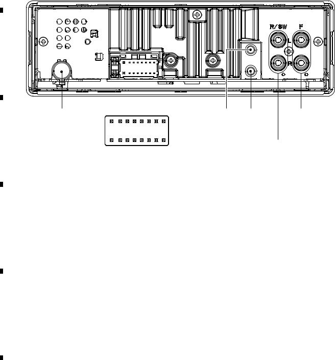
|
1 |
|
2 |
|
3 |
|
4 |
|
|
|
|
|
|
5.3 CONNECTOR FUNCTION DESCRIPTION
A
B |
|
|
|
|
|
|
|
|
|
ANTENNA INPUT |
|
|
|
|
|
|
MICROPHONE |
WIRED |
FRONT |
|
|
|
9 |
7 |
|
|
INPUT |
REMOTE |
OUTPUT |
|
15 |
13 11 |
5 |
3 |
1 |
CONTROL |
(EW5 Only) |
||
|
16 |
14 12 10 |
8 |
6 |
4 |
2 |
|
|
|
C |
|
|
|
|
|
|
|
REAR OUTPUT or |
|
|
|
|
|
|
|
|
|
||
1 |
FL+ |
|
|
9 |
NC |
SUBWOOFER OUTPUT |
|||
2 |
FR+ |
|
|
10 |
NC |
|
|
||
3 |
FL- |
|
|
11 |
NC |
|
|
||
4 |
FR- |
|
|
12 |
NC |
|
|
||
5 |
RL+ |
|
|
13 |
ACC |
|
|
||
6 |
RR+ |
|
|
14 |
B.REM |
|
|
||
7 |
RL- |
|
|
15 |
B.UP |
|
|
||
8 |
RR- |
|
|
16 |
GND |
|
|
||
D |
|
|
|
|
|
|
|
|
|
E
F
14 |
|
|
|
MVH-X360BT/XINEW5 |
|
|
|
|
|||
|
|
1 |
|
2 |
|
|
|
3 |
|
4 |
|
|
|
|
|
|
|
|
|
||||
Loading...