


PIONEER DEH-P645, DEH- P545, DEH-P645R, DEH-P545R, DEH-P544R Service Manual
...Service
Manual |
DEH-P645R |
|
ORDER NO. |
||
|
CRT2148
MULTI-CD CONTROL HIGH POWER CD PLAYER WITH RDS TUNER
DEH-P645R EW
DEH-P545R EW DEH-P544R EW
DEH-P443R EW
-See the separate manual CX-597(CRT1829) for the CD mechanism description, disassembly and circuit description.
-The CD mechanism employed in this model is one of S7 series.
CONTENTS
1. |
SAFETY INFORMATION ............................................ |
2 |
7. |
GENERAL INFORMATION ....................................... |
73 |
2. |
EXPLODED VIEWS AND PARTS LIST ....................... |
3 |
|
7.1 PARTS ................................................................. |
73 |
3. |
SCHEMATIC DIAGRAM ........................................... |
14 |
|
7.1.1 IC................................................................ |
73 |
4. |
PCB CONNECTION DIAGRAM ................................ |
40 |
|
7.1.2 DISPLAY .................................................... |
79 |
5. |
ELECTRICAL PARTS LIST ........................................ |
50 |
|
7.2 DIAGNOSIS ........................................................ |
80 |
6. |
ADJUSTMENT.......................................................... |
67 |
|
7.2.1 DISASSEMBLY ......................................... |
80 |
|
|
|
|
7.2.2 TEST MODE .............................................. |
81 |
|
|
|
|
7.3 BLOCK DIAGRAM .............................................. |
84 |
|
|
|
8. |
OPERATIONS AND SPECIFICATIONS..................... |
86 |
PIONEER ELECTRONIC CORPORATION 4-1, Meguro 1-Chome, Meguro-ku, Tokyo 153-8654, Japan PIONEER ELECTRONICS SERVICE INC. P.O.Box 1760, Long Beach, CA 90801-1760 U.S.A.
PIONEER ELECTRONIC [EUROPE] N.V. Haven 1087 Keetberglaan 1, 9120 Melsele, Belgium
PIONEER ELECTRONICS ASIACENTRE PTE.LTD. 501 Orchard Road, #10-00, Lane Wheelock Place, Singapore 23880
C PIONEER ELECTRONIC CORPORATION 1998
K-FEA. FEB. 1998 Printed in Japan

DEH-P645R,P545R,P544R,P443R
- CD Player Service Precautions
1.For pickup unit(CXX1230) handling, please refer to"Disassembly"(CX-597 Service Manual CRT1829). During replacement, handling precautions shall be taken to prevent an electrostatic discharge(protection by a short pin).
2.During disassembly, be sure to turn the power off since an internal IC might be destroyed when a connector is plugged or unplugged.
3.Please checking the grating after changing the service pickup unit(see page 71).
1. SAFETY INFORMATION
This service manual is intended for qualified service technicians; it is not meant for the casual do-it-yourselfer. Qualified technicians have the necessary test equipment and tools, and have been trained to properly and safely repair complex products such as those covered by this manual.
Improperly performed repairs can adversely affect the safety and reliability of the product and may void the warranty. If you are not qualified to perform the repair of this product properly and safely; you should not risk trying to do so and refer the repair to a qualified service technician.
1. Safety Precautions for those who Service this Unit.
•When checking or adjusting the emitting power of the laser diode exercise caution in order to get safe, reliable results.
Caution:
1.During repair or tests, minimum distance of 13cm from the focus lens must be kept.
2.During repair or tests, do not view laser beam for 10 seconds or longer.
2.A “CLASS 1 LASER PRODUCT” label is affixed to the rear of the player.
3.The triangular label is attached to the mechanism unit frame.
CLASS 1
LASER PRODUCT
4. Specifications of Laser Diode
Specifications of laser radiation fields to which human access is possible during service. Wavelength = 800 nanometers
2

DEH-P645R,P545R,P544R,P443R
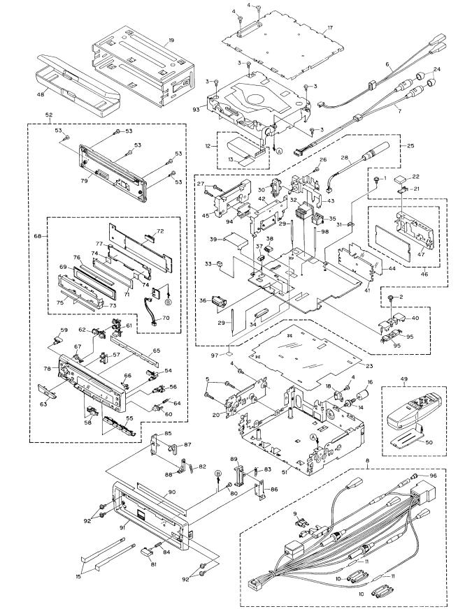
2. EXPLODED VIEWS AND PARTS LIST
2.1 PACKING
19
20
|
2 |
4 |
|
|
|
21 |
|
|
|
|
|
3 |
|
|
|
6 |
5 |
|
|
|
|
|
|
|
|
|
7 |
10 |
|
|
|
8 |
|
|
|
|
|
|
|
|
1 |
9 |
|
|
|
|
|
11 |
|
|
|
|
13 |
|
|
|
|
14 |
12 |
|
|
|
|
|
|
25 |
24 |
15 |
16 |
|
|
|||
26 |
|
|
|
|
27 |
23 |
17 |
|
|
|
|
|
||
|
|
|
|
|
|
|
18 |
|
|
22
Fig. 1
3
DEH-P645R,P545R,P544R,P443R
NOTE:
-Parts marked by "*"are generally unavailable because they are not in our Master Spare Parts List.
-Screws adjacent to mark on the product are used for disassembly.
-PACKING SECTION PARTS LIST
(1) PARTS LIST
Mark No. Description |
Part No. |
Mark No. Description |
Part No. |
||||
|
|
|
|
|
|
|
|
|
1 |
Cord Assy |
See Contrast table(2) |
18-4 |
Owner's Manual |
See Contrast table(2) |
|
|
2 |
Accessory Assy |
CEA1917 |
18-5 |
Owner's Manual |
See Contrast table(2) |
|
|
3 |
Screw |
CBA1284 |
18-6 |
Installation Manual |
See Contrast table(2) |
|
|
4 |
Handle |
CNC5395 |
18-7 |
Label |
See Contrast table(2) |
|
|
5 |
Bush |
CNV1009 |
18-8 |
Passport |
See Contrast table(2) |
|
* |
6 |
Polyethylene Bag |
E36-615 |
18-9 |
Warranty Card |
See Contrast table(2) |
|
|
7 |
Base Assy |
See Contrast table(2) |
18-10 |
Caution Card |
See Contrast table(2) |
|
* |
8 |
Sheet |
See Contrast table(2) |
19-1 |
Polyethylene Bag |
See Contrast table(2) |
|
|
9 |
Polyethylene Bag |
See Contrast table(2) |
19-2 |
Installation Manual |
See Contrast table(2) |
|
* |
10 |
Base |
See Contrast table(2) |
* 19-3 |
Label |
See Contrast table(2) |
|
|
11 |
Screw Assy |
See Contrast table(2) |
19-4 |
Passport |
See Contrast table(2) |
|
|
12 |
Screw |
See Contrast table(2) |
* 19-5 |
Warranty Card |
See Contrast table(2) |
|
|
13 |
Screw |
See Contrast table(2) |
20 |
Battery |
See Contrast table(2) |
|
* |
14 |
Polyethylene Bag |
See Contrast table(2) |
21 |
Carton |
See Contrast table(2) |
|
* |
15 |
Polyethylene Bag |
See Contrast table(2) |
22 |
Contain Box |
See Contrast table(2) |
|
|
16 |
Bracket |
See Contrast table(2) |
23 |
Protector |
CHP1766 |
|
|
17 |
Polyethylene Bag |
CEG-162 |
24 |
Protector |
CHP1767 |
|
|
18-1 |
Polyethylene Bag |
CEG1116 |
25 |
Spacer |
See Contrast table(2) |
|
|
18-2 |
Owner's Manual |
See Contrast table(2) |
26 |
Case Assy |
CXB1063 |
|
|
18-3 |
Owner's Manual |
See Contrast table(2) |
27 |
Remote Control Assy |
See Contrast table(2) |
|
- Owner’s Manual
Model |
Part No. |
Language |
DEH-P645R/EW |
CRD2557 |
English, Spanish |
|
CRD2558 |
German, French |
|
CRD2559 |
Italian, Dutch |
DEH-P545R/EW |
CRD2568 |
English, Spanish |
|
CRD2569 |
German, French |
|
CRD2570 |
Italian, Dutch |
DEH-P544R/EW |
CRD2631 |
English, Spanish, Italian |
DEH-P443R/EW |
CRD2633 |
German, French, Dutch |
- Installation Manual
Model |
Part No. |
Language |
DEH-P645R/EW |
CRD2560 |
English, Spanish, German, French, Italian, Dutch |
DEH-P545R/EW |
CRD2571 |
English, Spanish, German, French, Italian, Dutch |
DEH-P544R/EW |
CRD2632 |
English, Spanish, Italian |
DEH-P443R/EW |
CRD2634 |
German, French, Dutch |
4
DEH-P645R,P545R,P544R,P443R
(2) CONTRAST TABLE
DEH-P645R/EW, DEH-P545R/EW, DEH-P544R/EW and DEH-P443R/EW are constructed same except for the
following:
Mark No. Symbol and Description |
Part No. |
|||
DEH-P645R/EW |
DEH-P545R/EW |
|||
|
1 |
Cord Assy |
CDE5485 |
CDE5486 |
|
7 |
Base Assy |
CEA2344 |
Not used |
* |
8 |
Sheet |
CZA3371 |
Not used |
|
9 |
Polyethylene Bag |
CZE3188 |
Not used |
* |
10 |
Base |
CZN6466 |
Not used |
|
11 |
Screw Assy |
CZE3198 |
Not used |
|
12 |
Screw |
BNC40P120FZK |
Not used |
|
13 |
Screw |
BPZ30P100FZK |
Not used |
* |
14 |
Polyethylene Bag |
CEG-127 |
Not used |
* |
15 |
Polyethylene Bag |
CZE3201 |
Not used |
|
16 |
Bracket |
CZN6467 |
Not used |
|
18-2 |
Owner's Manual |
CRD2557 |
CRD2568 |
|
18-3 |
Owner's Manual |
CRD2558 |
CRD2569 |
|
18-4 |
Owner's Manual |
CRD2559 |
CRD2570 |
|
19-2 |
Installation Manual |
CRD2560 |
CRD2571 |
|
20 |
Battery |
CEX1006 |
Not used |
|
21 |
Carton |
CHG3436 |
CHG3440 |
|
22 |
Contain Box |
CHL3436 |
CHL3440 |
|
25 |
Spacer |
CHW1433 |
Not used |
|
27 |
Remote Control Assy |
CXB1160 |
Not used |
5
DEH-P645R,P545R,P544R,P443R
Mark No. Symbol and Description |
Part No. |
|||
DEH-P645R/EW |
DEH-P544R/EW |
|||
|
1 |
Cord Assy |
CDE5485 |
CDE5486 |
|
7 |
Base Assy |
CEA2344 |
Not used |
* |
8 |
Sheet |
CZA3371 |
Not used |
|
9 |
Polyethylene Bag |
CZE3188 |
Not used |
* |
10 |
Base |
CZN6466 |
Not used |
|
11 |
Screw Assy |
CZE3198 |
Not used |
|
12 |
Screw |
BNC40P120FZK |
Not used |
|
13 |
Screw |
BPZ30P100FZK |
Not used |
* |
14 |
Polyethylene Bag |
CEG-127 |
Not used |
* |
15 |
Polyethylene Bag |
CZE3201 |
Not used |
|
16 |
Bracket |
CZN6467 |
Not used |
|
18-2 |
Owner's Manual |
CRD2557 |
Not used |
|
18-3 |
Owner's Manual |
CRD2558 |
Not used |
|
18-4 |
Owner's Manual |
CRD2559 |
Not used |
|
18-5 |
Owner's Manual |
Not used |
CRD2631 |
|
18-6 |
Installation Manual |
Not used |
CRD2632 |
* 18-7 |
Label |
Not used |
CRW1343 |
|
* 18-9 |
Warranty Card |
Not used |
CRY1087 |
|
|
18-10 |
Caution Card |
CRP1182 |
Not used |
|
19-1 |
Polyethylene Bag |
CEG1116 |
Not used |
|
19-2 |
Installation Manual |
CRD2560 |
Not used |
* 19-3 |
Label |
CRW1343 |
Not used |
|
|
19-4 |
Passport |
CRY1013 |
Not used |
* 19-5 |
Warranty Card |
CRY1087 |
Not used |
|
|
20 |
Battery |
CEX1006 |
Not used |
|
21 |
Carton |
CHG3436 |
CHG3441 |
|
22 |
Contain Box |
CHL3436 |
CHL3441 |
|
25 |
Spacer |
CHW1433 |
Not used |
|
27 |
Remote Control Assy |
CXB1160 |
Not used |
6
DEH-P645R,P545R,P544R,P443R
Mark No. Symbol and Description |
Part No. |
|||
DEH-P645R/EW |
DEH-P443R/EW |
|||
|
1 |
Cord Assy |
CDE5485 |
CDE5627 |
|
7 |
Base Assy |
CEA2344 |
Not used |
* |
8 |
Sheet |
CZA3371 |
Not used |
|
9 |
Polyethylene Bag |
CZE3188 |
Not used |
* |
10 |
Base |
CZN6466 |
Not used |
|
11 |
Screw Assy |
CZE3198 |
Not used |
|
12 |
Screw |
BNC40P120FZK |
Not used |
|
13 |
Screw |
BPZ30P100FZK |
Not used |
* |
14 |
Polyethylene Bag |
CEG-127 |
Not used |
* |
15 |
Polyethylene Bag |
CZE3201 |
Not used |
|
16 |
Bracket |
CZN6467 |
Not used |
|
18-2 |
Owner's Manual |
CRD2557 |
Not used |
|
18-3 |
Owner's Manual |
CRD2558 |
Not used |
|
18-4 |
Owner's Manual |
CRD2559 |
Not used |
|
18-5 |
Owner's Manual |
Not used |
CRD2633 |
|
18-6 |
Installation Manual |
Not used |
CRD2634 |
* 18-7 |
Label |
Not used |
CRW1343 |
|
|
18-8 |
Passport |
Not used |
CRY1013 |
* 18-9 |
Warranty Card |
Not used |
CRY1087 |
|
|
18-10 |
Caution Card |
CRP1182 |
Not used |
|
19-1 |
Polyethylene Bag |
CEG1116 |
Not used |
|
19-2 |
Installation Manual |
CRD2560 |
Not used |
* 19-3 |
Label |
CRW1343 |
Not used |
|
|
19-4 |
Passport |
CRY1013 |
Not used |
* 19-5 |
Warranty Card |
CRY1087 |
Not used |
|
|
20 |
Battery |
CEX1006 |
Not used |
|
21 |
Carton |
CHG3436 |
CHG3442 |
|
22 |
Contain Box |
CHL3436 |
CHL3442 |
|
25 |
Spacer |
CHW1433 |
Not used |
|
27 |
Remote Control Assy |
CXB1160 |
Not used |
7
DEH-P645R,P545R,P544R,P443R
2.2 EXTERIOR
Fig. 2
8
DEH-P645R,P545R,P544R,P443R
- EXTERIOR SECTION PARTS LIST
(1) PARTS LIST
Mark No. Description |
Part No. |
|
Mark No. Description |
Part No. |
||
1 |
Screw |
ASZ26P055FUC |
46 |
FM/AM Tuner Unit |
See Contrast table(2) |
|
2 |
Screw |
ASZ26P080FMC |
47 |
Holder |
CNC6555 |
|
3 |
Screw |
BSZ26P050FMC |
48 |
Case Assy |
CXB1063 |
|
4 |
Screw |
BSZ30P060FMC |
49 |
Remote Control Assy |
See Contrast table(2) |
|
5 |
Screw |
BSZ30P180FMC |
50 |
Battery Cover |
See Contrast table(2) |
|
6 |
Cord Assy |
See Contrast table(2) |
51 |
Chassis Unit |
See Contrast table(2) |
|
7 |
Cord Assy |
See Contrast table(2) |
52 |
Detach Grille Assy |
See Contrast table(2) |
|
8 |
Cord Assy |
See Contrast table(2) |
53 |
Screw |
BPZ20P100FZK |
|
9 |
Fuse |
CEK1136 |
54 |
Button |
See Contrast table(2) |
|
10 |
Cap |
CNS1472 |
55 |
Button |
See Contrast table(2) |
|
11 |
Resistor |
RS1/2PMF102J |
56 |
Button |
CAC5399 |
|
12 |
Cable |
CDE5635 |
57 |
Button |
CAC5403 |
|
13 |
Insulator |
CNM5761 |
58 |
Button |
CAC5404 |
|
14 |
Screw |
CBA1284 |
59 |
Button |
See Contrast table(2) |
|
15 |
Handle |
CNC5395 |
60 |
Button |
See Contrast table(2) |
|
16 |
Bush |
CNV1009 |
61 |
Button |
See Contrast table(2) |
|
17 |
Case |
CNB2119 |
62 |
Button |
See Contrast table(2) |
|
18 |
Holder |
CNC4963 |
63 |
Button |
See Contrast table(2) |
|
19 |
Holder |
CNC6798 |
64 |
Spring |
CBH2103 |
|
20 |
Holder |
CNC6862 |
65 |
Cover |
CNM4704 |
|
21 |
Earth Terminal |
CNC7358 |
66 |
Lighting Conductor |
CNV5180 |
|
22 |
Spacer |
CNM4913 |
67 |
Lighting Conductor |
CNV5181 |
|
23 |
Insulator |
CNM5535 |
68 |
Keyboard Unit |
See Contrast table(2) |
|
24 |
Cap |
See Contrast table(2) |
69 |
LCD |
See Contrast table(2) |
|
25 |
Tuner Amp Unit |
See Contrast table(2) |
70 |
Cord |
CDE5665 |
|
26 |
Screw |
BPZ26P080FMC |
71 |
EL |
CEL1536 |
|
27 |
Screw |
BSZ26P140FMC |
72 |
Connector(CN1801) |
CKS3580 |
|
28 |
Antenna Cord |
CDH1234 |
73 |
Holder |
CNC7435 |
|
29 |
Clamper |
CEF1009 |
74 |
Film |
CNM4349 |
|
30 |
Pin Jack(CN253) |
CKB1028 |
75 |
Spacer |
CNM5449 |
|
31 |
Terminal(CN501) |
CKF1059 |
76 |
Connector |
CNV5182 |
|
32 |
Plug(CN901) |
CKM1278 |
77 |
Housing |
CNV5183 |
|
33 |
Plug(CN802) |
CKS-783 |
78 |
Grille Unit |
See Contrast table(2) |
|
34 |
Connector(CN651) |
CKS2228 |
79 |
Cover Unit |
See Contrast table(2) |
|
35 |
Connector(CN101) |
CKS3408 |
80 |
Screw |
BPZ20P060FMC |
|
36 |
Connector(CN801) |
CKS3581 |
81 |
Button |
CAC5180 |
|
37 |
Connector(CN851) |
See Contrast table(2) |
82 |
Spring |
CBH1834 |
|
38 |
Connector(CN254) |
See Contrast table(2) |
83 |
Spring |
CBH1835 |
|
39 |
Holder |
CNC5968 |
84 |
Spring |
CBH1996 |
|
40 |
Holder |
CNC6132 |
85 |
Bracket |
CNC6135 |
|
41 |
Holder |
CNC6356 |
86 |
Bracket |
CNC6791 |
|
42 |
Holder |
CNC7429 |
87 |
Arm |
CNV4692 |
|
43 |
Holder |
See Contrast table(2) |
88 |
Arm |
CNV4693 |
|
44 |
Insulator |
CNM4684 |
89 |
Arm |
CNV4951 |
|
45 |
Heat Sink |
CNR1458 |
90 |
Cover |
CNM4875 |
|
9
DEH-P645R,P545R,P544R,P443R
Mark No. Description |
Part No. |
|
91 |
Panel |
See Contrast table(2) |
92 |
Screw |
IMS20P030FZK |
93 |
CD Mechanism Module |
CXK5004 |
94 |
IC(IC201) |
See Contrast table(2) |
95 |
Transistor(Q951, 971) |
2SD2396 |
96 |
Terminal Cover |
CKX-003 |
97 |
Spacer |
CNM5875 |
98 |
Clamper |
See Contrast table(2) |
(2) CONTRAST TABLE
DEH-P645R/EW, DEH-P545R/EW, DEH-P544R/EW and DEH-P443R/EW are constructed same except for the
following:
Mark No. Symbol and Description |
Part No. |
||
DEH-P645R/EW |
DEH-P443R/EW |
||
6 |
Cord Assy |
CDE5185 |
Not used |
7 |
Cord Assy |
CDE5209 |
Not used |
8 |
Cord Assy |
CDE5485 |
CDE5627 |
24 |
Cap |
CNV2680 |
Not used |
25 |
Tuner Amp Unit |
CWM5619 |
CWM5621 |
37 |
Connector(CN851) |
CKS3597 |
Not used |
38 |
Connector(CN254) |
CKS3598 |
Not used |
43 |
Holder |
CNC7430 |
CNC7434 |
46 |
FM/AM Tuner Unit |
CWE1416 |
CWE1470 |
49 |
Remote Control Assy |
CXB1160 |
Not used |
50 |
Battery Cover |
CNS4406 |
Not used |
51 |
Chassis Unit |
CXB1981 |
CXB1990 |
52 |
Detach Grille Assy |
CXB1992 |
CXB2002 |
54 |
Button |
CAC5397 |
CAC5406 |
55 |
Button |
CAC5398 |
CAC5449 |
59 |
Button |
CAC5405 |
CAC5411 |
60 |
Button |
CAC5430 |
CAC5514 |
61 |
Button |
CAC5450 |
CAC5544 |
62 |
Button |
CAC5451 |
CAC5545 |
63 |
Button |
CAC5536 |
CAC5417 |
68 |
Keyboard Unit |
CWM5632 |
CWM5635 |
69 |
LCD |
CAW1458 |
CAW1464 |
78 |
Grille Unit |
CXB1965 |
CXB1967 |
79 |
Cover Unit |
CXB2480 |
CXB2481 |
91 |
Panel |
CNS4870 |
CNS4908 |
94 |
IC(IC201) |
TDA7386 |
TDA7384 |
98 |
Clamper |
CEF1009 |
Not used |
10
DEH-P645R,P545R,P544R,P443R
Mark No. Symbol and Description |
Part No. |
||
DEH-P645R/EW |
DEH-P545R/EW |
||
6 |
Cord Assy |
CDE5185 |
Not used |
7 |
Cord Assy |
CDE5209 |
Not used |
8 |
Cord Assy |
CDE5485 |
CDE5486 |
24 |
Cap |
CNV2680 |
Not used |
25 |
Tuner Amp Unit |
CWM5619 |
CWM5624 |
37 |
Connector(CN851) |
CKS3597 |
Not used |
38 |
Connector(CN254) |
CKS3598 |
Not used |
43 |
Holder |
CNC7430 |
CNC7434 |
49 |
Remote Control Assy |
CXB1160 |
Not used |
50 |
Battery Cover |
CNS4406 |
Not used |
51 |
Chassis Unit |
CXB1981 |
CXB1986 |
52 |
Detach Grille Assy |
CXB1992 |
CXB1998 |
68 |
Keyboard Unit |
CWM5632 |
CWM5638 |
69 |
LCD |
CAW1458 |
CAW1461 |
78 |
Grille Unit |
CXB1965 |
CXB1971 |
98 |
Clamper |
CEF1009 |
Not used |
Mark No. Symbol and Description |
Part No. |
||
DEH-P645R/EW |
DEH-P544R/EW |
||
6 |
Cord Assy |
CDE5185 |
Not used |
7 |
Cord Assy |
CDE5209 |
Not used |
8 |
Cord Assy |
CDE5485 |
CDE5486 |
24 |
Cap |
CNV2680 |
Not used |
25 |
Tuner Amp Unit |
CWM5619 |
CWM5624 |
37 |
Connector(CN851) |
CKS3597 |
Not used |
38 |
Connector(CN254) |
CKS3598 |
Not used |
43 |
Holder |
CNC7430 |
CNC7434 |
49 |
Remote Control Assy |
CXB1160 |
Not used |
50 |
Battery Cover |
CNS4406 |
Not used |
51 |
Chassis Unit |
CXB1981 |
CXB1987 |
52 |
Detach Grille Assy |
CXB1992 |
CXB1999 |
54 |
Button |
CAC5397 |
CAC5406 |
55 |
Button |
CAC5398 |
CAC5449 |
59 |
Button |
CAC5405 |
CAC5411 |
60 |
Button |
CAC5430 |
CAC5514 |
61 |
Button |
CAC5450 |
CAC5544 |
62 |
Button |
CAC5451 |
CAC5545 |
63 |
Button |
CAC5536 |
CAC5417 |
68 |
Keyboard Unit |
CWM5632 |
CWM5639 |
69 |
LCD |
CAW1458 |
CAW1464 |
78 |
Grille Unit |
CXB1965 |
CXB1972 |
79 |
Cover Unit |
CXB2480 |
CXB2481 |
91 |
Panel |
CNS4870 |
CNS4780 |
98 |
Clamper |
CEF1009 |
Not used |
11

DEH-P645R,P545R,P544R,P443R
2.3 CD MECHANISM MODULE
Fig. 3
12
DEH-P645R,P545R,P544R,P443R
- CD MECHANISM MODULE SECTION PARTS LIST
Mark No. Description |
Part No. |
|
Mark No. Description |
Part No. |
||
|
|
|
|
|
|
|
1 |
Control Unit |
CWX2224 |
46 |
Connector(CN701) |
CKS2774 |
|
2 |
Pickup Unit(Service) |
CXX1230 |
47 |
Connector(CN801) |
CKS2196 |
|
3 |
Screw |
IMS26P035FMC |
48 |
Spring |
CBH1832 |
|
4 |
Screw |
BMZ20P025FMC |
49 |
Spring |
CBH1833 |
|
5 |
Screw |
BMZ20P040FMC |
50 |
Roller |
CLA2627 |
|
6 |
Screw |
BSZ20P040FMC |
51 |
Arm |
CNV4136 |
|
7 |
Screw |
CBA1077 |
52 |
Arm Unit |
CXA8565 |
|
8 |
Screw |
CBA1250 |
53 |
Bracket |
CNC6056 |
|
9 |
Screw |
CBA1296 |
54 |
Load Motor Unit(S7) |
CXA8702 |
|
10 |
Screw |
CBA1362 |
55 |
Screw |
JFZ20P025FMC |
|
11 |
Spring |
CBH1724 |
56 |
Arm |
CNV4120 |
|
12 |
Spring |
CBH1729 |
57 |
Roller |
CNV4509 |
|
13 |
Spring |
CBH1730 |
58 |
Gear Unit(S7) |
CXA8701 |
|
14 |
Spring |
CBH1731 |
59 |
Screw |
CBA1296 |
|
15 |
Spring |
CBH1732 |
60 |
Frame |
CNC5797 |
|
16 |
Spring |
CBH1745 |
61 |
Damper |
CNV3974 |
|
17 |
Spring |
CBH1848 |
62 |
Spring |
CBH1736 |
|
18 |
Spring |
CBH1849 |
63 |
Spring |
CBH1863 |
|
19 |
Spring |
CBH1939 |
64 |
Spring |
CBH1945 |
|
20 |
Spring |
CBL1214 |
65 |
Spring |
CBL1269 |
|
21 |
Roller |
CLA2627 |
66 |
Arm |
CNC5799 |
|
22 |
Frame |
CNC5796 |
67 |
Lever |
CNC6054 |
|
23 |
Bracket |
CNC5871 |
68 |
Spacer |
CNM3315 |
|
* 24 |
Bracket |
CNC6376 |
69 |
Sheet |
CNM4849 |
|
25 |
Cushion |
CNM3917 |
70 |
Arm |
CNV5436 |
|
26 |
Sheet |
CNM4873 |
71 |
Arm |
CNV4123 |
|
27 |
••••• |
|
72 |
Arm |
CNV4124 |
|
28 |
PCB |
CNP4230 |
73 |
Arm |
CNV4125 |
|
29 |
Bearing |
CNR1415 |
74 |
Arm |
CNV4138 |
|
30 |
Belt |
CNT1071 |
75 |
Arm |
CNV4139 |
|
31 |
Damper |
CNV3974 |
76 |
Clamper |
CNV5308 |
|
32 |
Gear |
CNV4128 |
77 |
Screw |
CBA1250 |
|
33 |
Gear |
CNV4129 |
78 |
Connector(CN1) |
CDE4576 |
|
34 |
Gear |
CNV4130 |
79 |
Arm |
CNC7383 |
|
35 |
Gear |
CNV4131 |
|
* 80 Gathering PCB |
CNX2445 |
|
36 |
Holder |
CNV4663 |
81 |
Photo-transistor(Q1, 2) |
CPT-230S-X |
|
37 |
Holder |
CNV5071 |
82 |
ELBO Arm Assy(S7) |
CXA8889 |
|
38 |
Guide |
CNV4484 |
83 |
Load Motor Assy(S7) |
CXA8891 |
|
39 |
Screw Unit(S7) |
CXA8699 |
84 |
LO Arm Assy(S7) |
CXA8892 |
|
40 |
CRG Motor Unit(S7) |
CXA8986 |
85 |
Shaft |
CLA3133 |
|
41 |
Motor Unit |
CXA8912 |
86 |
Guide Arm Assy(S7) |
CXB1850 |
|
42 |
Lever Unit |
CXA9300 |
87 |
Ball |
CNR1189 |
|
43 |
Chassis Unit |
CXB2574 |
|
|
|
|
44 |
Screw |
JFZ20P025FMC |
|
|
|
|
45 |
Connector(CN101) |
CKS1953 |
|
|
|
|
13
|
1 |
|
2 |
|
3 |
|
4 |
|
|
|
|
|
|
DEH-P645R,P545R,P544R,P443R
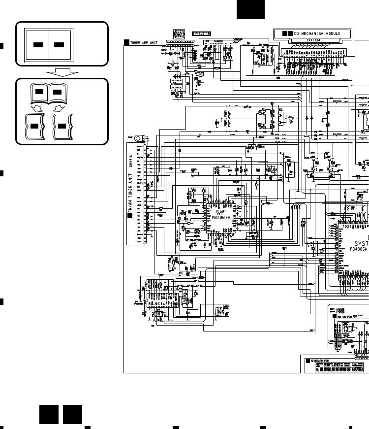
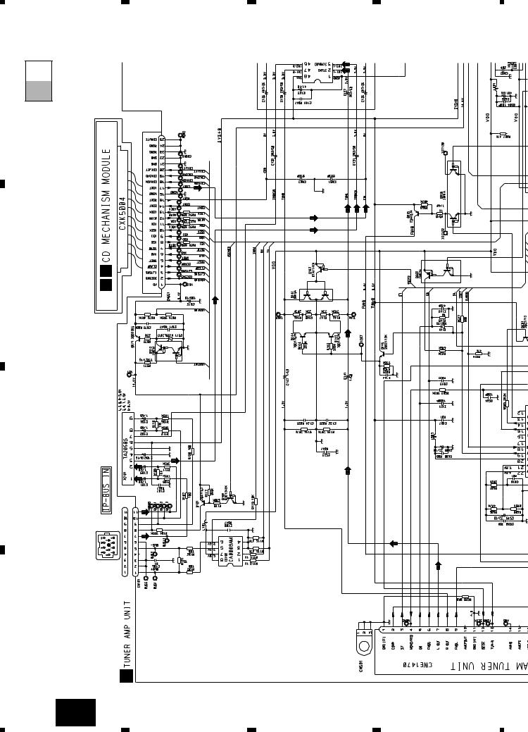
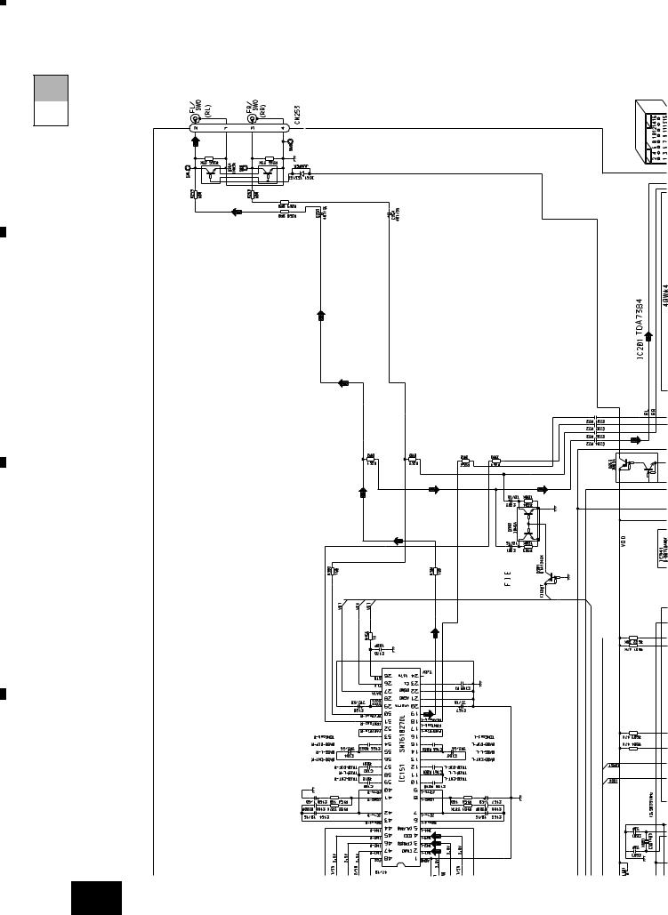
3. SCHEMATIC DIAGRAM
3.1 OVERALL CONNECTION DIAGRAM(GUIDE PAGE)
A
Note: When ordering service parts, be sure to refer to “EXPLODED VIEWS AND PARTS LIST” or “ELECTRICAL PARTS
|
LIST”. |
|
|
|
A-a |
|
- DEH-P645R/EW,DEH-P545R/EW,DEH-P544R/EW |
|
|||||
|
|
|
|
|
|
|
|
|
|
Large size |
|
|
D E |
|
|
|
|
|
|
|
|
A-a |
A-b |
SCH diagram |
A |
|
|
|
|
|
|
|
||
|
A-a |
A-b |
Guide page |
|
|
|
|
|
|
|
|
||
B |
|
|
|
|
|
|
|
A-a |
A-b |
Detailed page |
|
|
|
|
|
|
|
|
||
|
|
|
|
B |
|
|
C |
|
|
|
|
|
|
|
|
|
|
|
|
F |
D |
|
|
|
|
|
C |
|
|
|
|
|
|
|
14 |
A F |
|
|
|
||
|
1 |
|
|
2 |
3 |
4 |

|
5 |
|
6 |
|
7 |
|
8 |
|
|
|
|
|
|
DEH-P645R,P545R,P544R,P443R
A
A-b |
B
C
|
|
|
|
RRRR+ |
|
|
||
|
|
|
|
|
|
|
|
|
BUP |
|
FR- |
FR+ |
|
|
|||
|
|
|
|
|
|
|
|
|
ILL B.REMOTE |
|
FL- |
FL+ |
|
|
|||
|
|
|
|
|
|
|
|
|
GND ACC |
RL- |
RL+ |
|
|
||||
|
|
|
|
|
|
|
|
|
|
|
|
|
|
|
|
|
|
|
|
|
|
|
|
|
|
|
D
Fig. 4
A 15
|
5 |
|
6 |
|
7 |
|
8 |
|
|
|
|
|
|
||||
|
|
|
|
|

|
|
1 |
2 |
3 |
4 |
|
DEH-P645R,P545R,P544R,P443R |
|
|
||
|
A-b |
|
|
|
|
A |
A-a |
|
|
|
|
B |
|
E |
|
|
|
|
D |
|
|
|
|
|
|
|
|
|
|
C |
|
|
|
|
|
D |
|
|
|
|
|
|
|
A |
|
|
B |
|
|
|
|
|
|
|
16 |
A-a |
|
|
|
|
|
1 |
2 |
3 |
4 |

|
5 |
|
6 |
|
7 |
|
8 |
|
|
|
|
|
|
DEH-P645R,P545R,P544R,P443R
|
|
|
|
A-b |
|
|
|
|
A-a |
|
|
F |
|
|
|
|
C |
|
|
B |
|
|
|
|
|
|
|
|
Fig.5 |
|
|
A-a |
F |
17 |
|
|
|
|
|
5 |
6 |
7 |
8 |
|
A
B
C
D

|
|
1 |
2 |
3 |
4 |
|
DEH-P645R,P545R,P544R,P443R |
|
|
||
|
A-b |
|
|
|
|
A |
A-a |
|
|
|
|
B |
|
|
|
|
|
C |
|
|
|
|
|
D |
|
|
|
|
|
|
18 |
A-b |
2 |
3 |
4 |
|
|
1 |
|||

5 |
|
|
6 |
7 |
8 |
|
RR+ FR+ |
FL+ |
RL+ |
DEH-P645R,P545R,P544R,P443R |
|
||
RR- |
FR- |
FL- |
RL- |
|
||
|
|
|
||||
|
BUP |
ILL B.REMOTE |
GND ACC |
|
|
|
|
|
|
|
|
A-b |
|
|
|
|
|
|
A-a |
A |
|
|
|
|
|
|
B |
|
|
|
|
|
|
C |
|
|
|
|
|
|
D |
|
|
|
|
|
Fig. 6 |
|
A-b 19
|
5 |
|
6 |
|
7 |
|
8 |
|
|
|
|
|
|
||||
|
|
|
|
|

|
1 |
|
2 |
|
3 |
|
4 |
|
|
|
|
|
|
DEH-P645R,P545R,P544R,P443R
3.2 OVERALL CONNECTION DIAGRAM(GUIDE PAGE)
- DEH-P443R/EW
A
|
|
|
|
|
|
A-a |
|
|
|
Large size |
|
|
D E |
|
A-a |
A-b |
SCH diagram |
A |
|
|
|
|
|
|
|||
|
A-a |
A-b |
Guide page |
|
|
|
|
|
|
|
|
||
B |
|
|
|
|
|
|
|
A-a |
A-b |
Detailed page |
|
|
|
|
|
|
|
|
||
|
|
|
|
B |
|
|
C |
|
|
|
|
|
|
|
|
|
|
|
|
F |
D |
|
|
|
|
|
C |
20 |
A F |
|
|
|
||
|
1 |
|
|
2 |
3 |
4 |
|
5 |
|
6 |
|
7 |
|
8 |
|
|
|
|
|
|
DEH-P645R,P545R,P544R,P443R
A
A-b
B
C
|
|
|
RRRR+ |
|
|
|||
|
|
|
|
|
|
|
|
|
BUP |
|
FR- |
FR+ |
|
|
|||
|
|
|
|
|
|
|
|
|
ILL B.REMOTE |
|
FL- |
FL+ |
|
|
|||
|
|
|
|
|
|
|
|
|
GND ACC |
|
RL- |
RL+ |
|
|
|||
|
|
|
|
|
|
|
|
|
|
|
|
|
|
|
|
|
|
D
Fig. 7
A 21
|
5 |
|
6 |
|
7 |
|
8 |
|
|
|
|
|
|
||||
|
|
|
|
|
|
|
1 |
2 |
3 |
4 |
|
DEH-P645R,P545R,P544R,P443R |
|
|
||
|
A-b |
|
|
|
|
A |
A-a |
|
|
|
|
B |
|
|
E |
|
|
|
|
D |
|
|
|
|
|
|
|
|
|
C |
|
|
|
|
|
D |
|
|
|
|
|
|
|
|
A |
|
|
|
22 |
A-a |
|
|
|
|
|
1 |
2 |
3 |
4 |

5 |
6 |
7 |
8 |
|
|
|
|
DEH-P645R,P545R,P544R,P443R |
|
||
|
|
|
|
A-b |
|
|
|
|
|
A-a |
A |
|
|
F |
|
|
|
|
|
C |
|
|
|
|
|
|
|
|
B |
|
|
|
|
|
C |
|
|
|
|
|
D |
B |
|
|
|
|
|
|
|
|
|
Fig. 8 |
|
|
|
A-a |
F |
23 |
|
|
|
|
|
||
5 |
6 |
7 |
8 |
|
|
A
B
C
D
1 |
|
2 |
|
3 |
|
4 |
|
|
|
|
|
DEH-P645R,P545R,P544R,P443R
A-a A-b
24 A-b
|
1 |
|
2 |
|
3 |
|
4 |
|
|
|
|
|
|
||||
|
|
|
|
|

5 |
6 |
|
|
7 |
8 |
|
RR+ |
FR+ |
FL+ |
RL+ |
DEH-P645R,P545R,P544R,P443R |
|
|
RR- |
FR- |
FL- |
RL- |
|
|
|
|
BUP |
ILL B.REMOTE |
GND ACC |
|
|
|
|
|
|
|
|
A-b |
|
|
|
|
|
|
A-a |
A |
|
|
|
|
|
|
B |
|
|
|
|
|
|
C |
|
|
|
|
D |
|
|
|
|
Fig. 9 |
|
|
|
A-b |
25 |
5 |
6 |
7 |
8 |
|

|
1 |
|
2 |
|
3 |
|
4 |
|
|
|
|
|
|
DEH-P645R,P545R,P544R,P443R
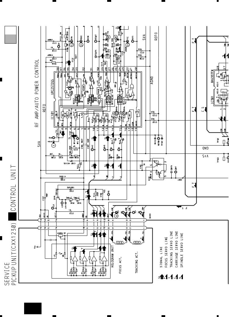
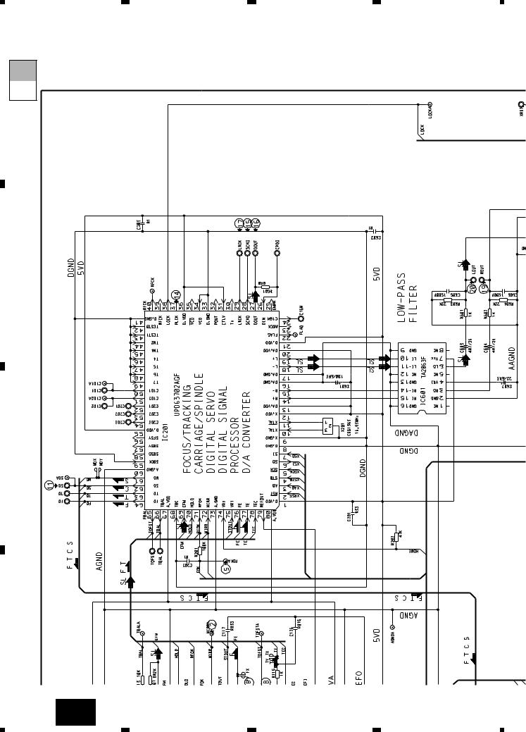
3.3 CD MECHANISM MODULE(GUIDE PAGE)
A
|
|
|
|
|
|
|
|
|
Large size |
|
|
|
|
|
|
|
|
|
SCH diagram |
|
|
|
A-a |
|
|
A-b |
|
||
|
|
|
|
|
|
|
|
||
|
|
|
|
|
|
|
|
|
|
|
|
|
|
|
|
|
|
|
|
|
|
|
|
|
|
|
|
|
|
|
|
|
|
|
|
|
|
|
|
D-a
D
A-a |
A-b |
Guide page |
|
Detailed page
A-a A-b
B
C
22/6R3
E 


CXA8912
BA05SFP
CXA8986
CXA8702
D
26 D E
|
1 |
|
2 |
|
3 |
|
4 |
|
|
|
|
|
|
||||
|
|
|
|
|

|
5 |
|
6 |
|
7 |
|
8 |
|
|
|
|
|
|
DEH-P645R,P545R,P544R,P443R
A
D-b
B
C
D
Fig. 10
D 27
|
5 |
|
6 |
|
7 |
|
8 |
|
|
|
|
|
|
||||
|
|
|
|
|
|
|
1 |
2 |
3 |
4 |
|
DEH-P645R,P545R,P544R,P443R |
|
|
||
|
D-b |
|
|
|
|
A |
D-a |
|
|
|
|
B |
|
|
|
|
|
C |
|
|
|
|
|
|
D |
|
|
|
|
D |
|
|
|
|
|
|
28 |
D-a |
|
|
|
|
|
1 |
2 |
3 |
4 |

|
5 |
|
6 |
|
7 |
|
8 |
|
|
|
|
DEH-P645R,P545R,P544R,P443R
D-a D-b
22/6R3 |
BA05SFP |
A
B
C
CXA8912 |
CXA8986 |
CXA8702 |
 D E
D E
Fig. 11
D-a E 29
|
5 |
|
6 |
|
7 |
|
8 |
|
|
|
|
|
|
||||
|
|
|
|
|
|
|
1 |
2 |
3 |
4 |
|
DEH-P645R,P545R,P544R,P443R |
|
|
||
|
D-b |
|
|
|
|
A |
D-a |
|
|
|
|
B |
|
|
|
|
|
C |
|
|
|
|
|
D |
|
|
|
|
|
|
30 |
D-b |
|
|
|
|
|
1 |
2 |
3 |
4 |
 Loading...