


DEH-P6000UB
Table of contents
 Loading...
CD RDS RECEIVER
ORDER NO.
CRT4036
DEH-P6000UB/XN/EW5
DEH-P6000UB
This service manual should be used together with the following manual(s):
Model No. Order No. Mech.Module Remarks
CX-3240 CRT4050
S10.5COMP2-iPod/USB
CD Mech. Module : Circuit Descriptions, Mech. Descriptions, Disassembly
/XN/EW5
For details, refer to "Important Check Points for Good Servicing".
PIONEER CORPORATION 4-1, Meguro 1-chome, Meguro-ku, Tokyo 153-8654, Japan
PIONEER ELECTRONICS (USA) INC. P.O. Box 1760, Long Beach, CA 90801-1760, U.S.A.
PIONEER EUROPE NV Haven 1087, Keetberglaan 1, 9120 Melsele, Belgium
PIONEER ELECTRONICS ASIACENTRE PTE. LTD. 253 Alexandra Road, #04-01, Singapore 159936
PIONEER CORPORATION 2007
K-ZZW. OCT. 2007 Printed in Japan
1234
SAFETY INFORMATION
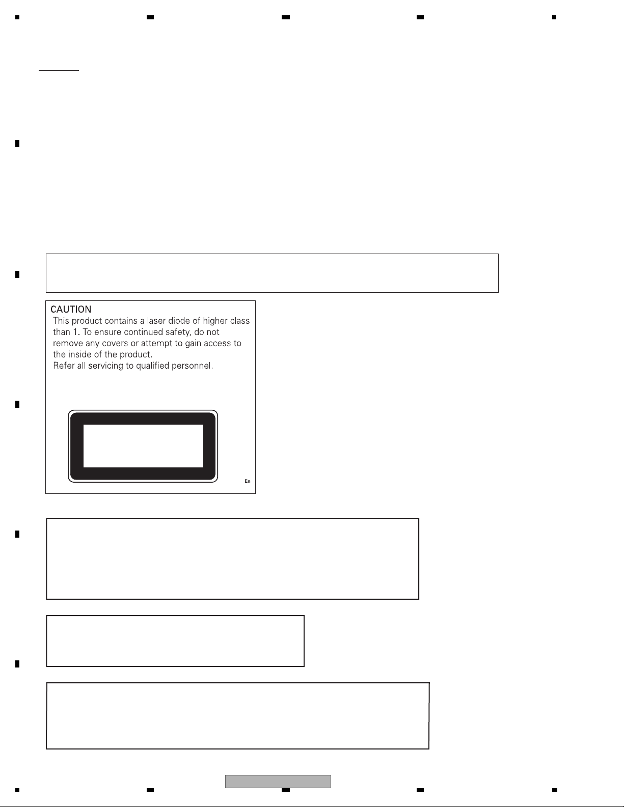
CAUTION
A
This service manual is intended for qualified service technicians; it is not meant for the casual do-it-yourselfe.
Qualified technicians have the necessary test equipment and tools, and have been trained to properly and safely repair
complex products such as those covered by this manual.
Improperly performed repairs can adversely affect the safety and reliability of the product and may void the warranty.
If you are not qualified to perform the repair of this product properly and safely, you should not risk trying to do so
and refer the repair to a qualified service technician.
- Safety Precautions for those who Service this Unit.
When checking or adjusting the emitting power of the laser diode exercise caution in order to get safe, reliable
results.
B
Caution:
1. During repair or tests, minimum distance of 13 cm from the focus lens must be kept.
2. During repair or tests, do not view laser beam for 10 seconds or longer.
CAUTION:
USE OF CONTROLS OR ADJUSTMENTS OR PERFORMANCE OF PROCEDURES OTHER THAN THOSE
SPECIFIED HEREIN MAY RESULT IN HAZARDOUS RADIATION EXPOSURE.
C
CLASS 1
LASER PRODUCT
D
WARNING!
The AEL (accessible emission level )of the laser power output is less than CLASS 1
but the laser component is capable of emitting radiation exceeding the limit for
CLASS 1.
A specially instructed person should do servicing operation of the apparatus.
E
Laser diode characteristics
Wave length : 785 nm to 814 nm
Maximum output : 1 190 W(Emitting period : unlimited)
Additional Laser Caution
Transistors Q101 in PCB drive the laser diodes.
When Q101 is shorted between their terminals, the laser diodes will radiate beam.
F
If the top cover is removed with no disc loaded while such short-circuit is continued,
the naked eyes may be exposed to the laser beam.
2
1234
DEH-P6000UB/XN/EW5
5 678
CAUTION
Danger of explosion if battery is incorrectly replaced.
Replaced only with the same or equivalent type recommended by the manufacture.
Discord used batteries according to the manufacture's instructions.
A
B
C
D
E
56
DEH-P6000UB/XN/EW5
F
7
8
3
1234
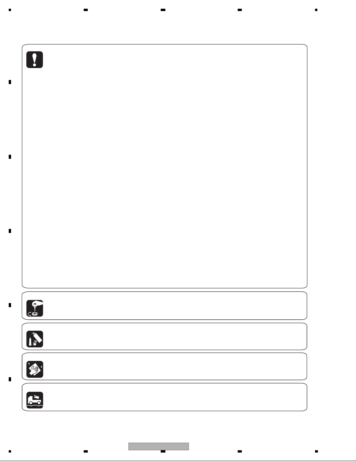
[Important Check Points for Good Servicing]
In this manual, procedures that must be performed during repairs are marked with the below symbol.
Please be sure to confirm and follow these procedures.
A
B
C
D
1. Product safety
Please conform to product regulations (such as safety and radiation regulations), and maintain a safe servicing environment by
following the safety instructions described in this manual.
1 Use specified parts for repair.
Use genuine parts. Be sure to use important parts for safety.
2 Do not perform modifications without proper instructions.
Please follow the specified safety methods when modification(addition/change of parts) is required due to interferences such as
radio/TV interference and foreign noise.
3 Make sure the soldering of repaired locations is properly performed.
When you solder while repairing, please be sure that there are no cold solder and other debris.
Soldering should be finished with the proper quantity. (Refer to the example)
4 Make sure the screws are tightly fastened.
Please be sure that all screws are fastened, and that there are no loose screws.
5 Make sure each connectors are correctly inserted.
Please be sure that all connectors are inserted, and that there are no imperfect insertion.
6 Make sure the wiring cables are set to their original state.
Please replace the wiring and cables to the original state after repairs.
In addition, be sure that there are no pinched wires, etc.
7 Make sure screws and soldering scraps do not remain inside the product.
Please check that neither solder debris nor screws remain inside the product.
8 There should be no semi-broken wires, scratches, melting, etc. on the coating of the power cord.
Damaged power cords may lead to fire accidents, so please be sure that there are no damages.
If you find a damaged power cord, please exchange it with a suitable one.
9 There should be no spark traces or similar marks on the power plug.
When spark traces or similar marks are found on the power supply plug, please check the connection and advise on secure
connections and suitable usage. Please exchange the power cord if necessary.
a Safe environment should be secured during servicing.
When you perform repairs, please pay attention to static electricity, furniture, household articles, etc. in order to prevent injuries.
Please pay attention to your surroundings and repair safely.
2. Adjustments
To keep the original performance of the products, optimum adjustments and confirmation of characteristics within specification.
Adjustments should be performed in accordance with the procedures/instructions described in this manual.
3. Lubricants, Glues, and Replacement parts
Use grease and adhesives that are equal to the specified substance.
E
Make sure the proper amount is applied.
4. Cleaning
For parts that require cleaning, such as optical pickups, tape deck heads, lenses and mirrors used in projection monitors, proper
cleaning should be performed to restore their performances.
5. Shipping mode and Shipping screws
To protect products from damages or failures during transit, the shipping mode should be set or the shipping screws should be
installed before shipment. Please be sure to follow this method especially if it is specified in this manual.
F
4
1234
DEH-P6000UB/XN/EW5

5 678
CONTENTS
SAFETY INFORMATION .....................................................................................................................................2
1. SERVICE PRECAUTIONS................................................................................................................................6
1.1 SERVICE PRECAUTIONS.........................................................................................................................6
1.2 NOTES ON SOLDERING...........................................................................................................................6
2. SPECIFICATIONS.............................................................................................................................................7
2.1 SPECIFICATIONS ......................................................................................................................................7
2.2 DISC/CONTENT FORMAT .........................................................................................................................8
2.3 PANEL FACILITIES ....................................................................................................................................9
2.4 CONNECTION DIAGRAM........................................................................................................................12
3. BASIC ITEMS FOR SERVICE........................................................................................................................13
3.1 CHECK POINTS AFTER SERVICING .....................................................................................................13
3.2 PCB LOCATION .......................................................................................................................................13
3.3 JIGS LIST .................................................................................................................................................14
4. BLOCK DIAGRAM ..........................................................................................................................................16
5. DIAGNOSIS ....................................................................................................................................................19
5.1 OPERATIONAL FLOWCHART.................................................................................................................19
5.2 ERROR CODE LIST.................................................................................................................................20
5.3 CONNECTOR FUNCTION DESCRIPTION .............................................................................................22
6. SERVICE MODE.............................................................................................................................................23
6.1 CD TEST MODE.......................................................................................................................................23
7. DISASSEMBLY...............................................................................................................................................25
8. EACH SETTING AND ADJUSTMENT............................................................................................................30
8.1 CD ADJUSTMENT ...................................................................................................................................30
8.2 CHECKING THE GRATING AFTER CHANGING THE PICKUP UNIT ....................................................31
8.3 PCL OUTPUT CONFIRMATION ..............................................................................................................33
9. EXPLODED VIEWS AND PARTS LIST ..........................................................................................................34
9.1 PACKING..................................................................................................................................................34
9.2 EXTERIOR(1)...........................................................................................................................................36
9.3 EXTERIOR(2)...........................................................................................................................................38
9.4 CD MECHANISM MODULE .....................................................................................................................40
10. SCHEMATIC DIAGRAM................................................................................................................................42
10.1 OVERALL CONNECTION DIAGRAM(GUIDE PAGE)............................................................................42
10.2 KEYBOARD UNIT ..................................................................................................................................48
10.3 CD MECHANISM MODULE(GUIDE PAGE)...........................................................................................50
10.4 WAVEFORMS.........................................................................................................................................56
11. PCB CONNECTION DIAGRAM ....................................................................................................................60
11.1 TUNER AMP UNIT .................................................................................................................................60
11.2 KEYBOARD UNIT...................................................................................................................................64
11.3 CD CORE UNIT(S10.5COMP2-iPod).....................................................................................................66
11.4 PANEL UNIT ...........................................................................................................................................68
12. ELECTRICAL PARTS LIST...........................................................................................................................69
A
B
C
D
56
DEH-P6000UB/XN/EW5
E
F
7
8
5

1234
1. SERVICE PRECAUTIONS
1.1 SERVICE PRECAUTIONS
A
1. You should conform to the regulations governing
the product (safety, radio and noise, and other
regulations), and should keep the safety during
servicing by following the safety instructions
described in this manual.
2. Before disassembling the unit, be sure to turn off
the power. Unplugging and plugging the connectors
during power-on mode may damage the ICs inside
the unit.
3. To protect the pickup unit from electrostatic discharge
B
during servicing, take an appropriate treatment
(shorting-solder) by referring to "the DISASSEMBLY".
4. After replacing the pickup unit, be sure to check the
grating.
5. Be careful in handling ICs. Some ICs such as MOS
type are so fragile that they can be damaged by
electrostatic induction.
C
1.2 NOTES ON SOLDERING
D
For environmental protection, lead-free solder is used on the printed circuit boards mounted in this unit.
Be sure to use lead-free solder and a soldering iron that can meet specifications for use with lead-free solders for repairs
accompanied by reworking of soldering.
Compared with conventional eutectic solders, lead-free solders have higher melting points, by approximately 40 C.
Therefore, for lead-free soldering, the tip temperature of a soldering iron must be set to around 373 C in general, although
the temperature depends on the heat capacity of the PC board on which reworking is required and the weight of the tip of
the soldering iron.
Compared with eutectic solders, lead-free solders have higher bond strengths but slower wetting times and higher melting
E
temperatures (hard to melt/easy to harden).
The following lead-free solders are available as service parts:
Parts numbers of lead-free solder:
GYP1006 1.0 in dia.
GYP1007 0.6 in dia.
GYP1008 0.3 in dia.
F
6
1234
DEH-P6000UB/XN/EW5

5 678
2. SPECIFICATIONS
2.1 SPECIFICATIONS
A
B
C
D
E
56
DEH-P6000UB/XN/EW5
F
7
8
7

1234
2.2 DISC/CONTENT FORMAT
A
B
C
D
E
F
8
1234
DEH-P6000UB/XN/EW5

5 678
2.3 PANEL FACILITIES
A
B
C
D
E
56
DEH-P6000UB/XN/EW5
F
7
8
9

1234
A
B
C
D
E
F
10
1234
DEH-P6000UB/XN/EW5
5 678
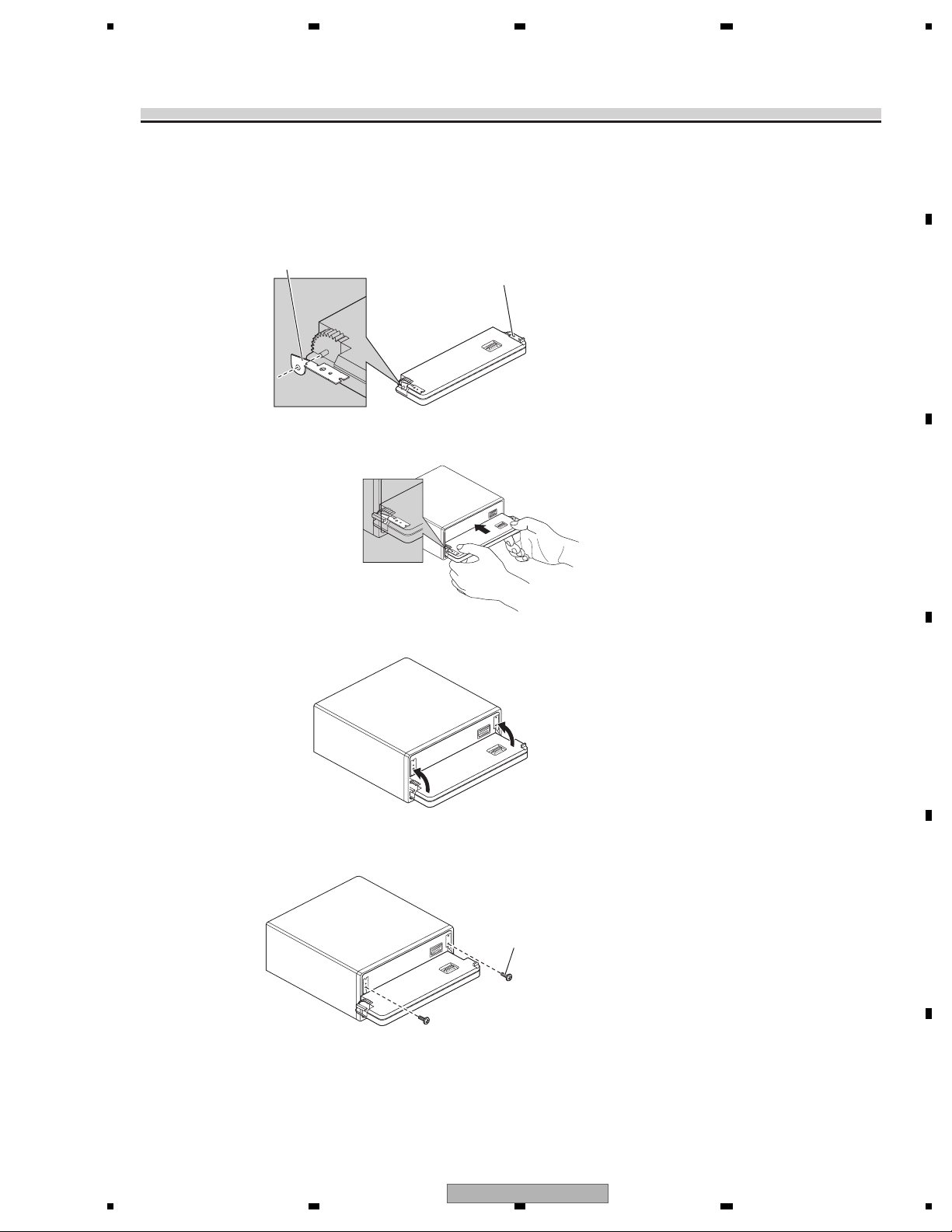
Fixing the front panel
If you do not operate the removing and attaching the front panel function, use the supplied
fixing screws and holders to fix the front panel to this unit.
1. Attach the holders to both sides of the front panel.
Holder
CND1249
2. Replace the front panel to the unit.
Holder
CND1250
A
B
C
3.
Flip the holders into upright positions.
4. Fix the front panel to the unit using fixing screws.
Fixing Screw
BPZ20P060FTB
D
E
56
DEH-P6000UB/XN/EW5
F
7
8
11

1234
2.4 CONNECTION DIAGRAM
A
B
C
D
E
F
12
1234
DEH-P6000UB/XN/EW5
5 678
3. BASIC ITEMS FOR SERVICE
3.1 CHECK POINTS AFTER SERVICING
To keep the product quality after servicing, please confirm following check points.
1 Confirm whether the customer complain has
been solved.
If the customer complain occurs with the
specific media, use it for the operation check.
2 CD Play back a CD.
(Track search)
3 FM/AM tuner Check FM/AM tuner action.
(Seek, Preset)
Switch band to check both FM and AM.
4 Check whether no disc is inside the product. The media used for the operating check must
See the table below for the items to be checked regarding audio:
Item to be checked regarding audio
Distortion
Noise
Volume too low
Volume too high
Volume fluctuating
Sound interrupted
demrifnocebotmetIserudecorP.oN
The customer complain must not be
reappeared.
Display, audio and operations must be
normal.
No malfunction on display, audio and
operation.
Display, audio and operations must be
normal.
be ejected.
receiving it for service.
A
B
retfaecnaraeppastinotridrosehctarcsoNkcehcecnaraeppA5
C
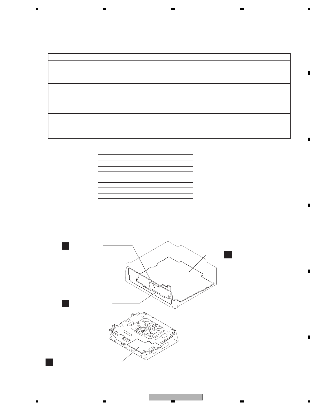
3.2 PCB LOCATION
Panel Unit
C
Keyboard Unit
B
CD Core Unit
D
(S10.5COMP2-iPod)
Tuner Amp Unit
A
Unit Number : QWM3010
Unit Name : Tuner Amp Unit
Unit Number :
Unit Name : Keyboard Unit
Unit Number : CWM8758
Unit Name : Panel Unit
Unit Number : CWX3526
Unit Name : CD Core Unit
(S10.5COMP2-iPod)
D
E
F
56
DEH-P6000UB/XN/EW5
7
8
13
1234
Name
Jig
e
3.3 JIGS LIST
- Jigs List
A
Name
Test Disc
L.P.F.
- Grease List
B
Name
m
Grease
Grease
Jig No.
No.
TCD-782
Grease No.
rease No.
GEM1024
GEM1045
emarks
Remarks
Checking the grating
Checking the grating (Two pieces)
emarks
Remarks
CD Mechanism Module
CD Mechanism Module
C
Before shipping out the product, be sure to clean the
following portions by using the prescribed cleaning
tools:
Portions to be cleaned Cleaning tools
CD pickup lenses
Cleaning liquid : GEM1004
Cleaning paper : GED-008
D
E
F
14
1234
DEH-P6000UB/XN/EW5

5 678
A
B
C
D
E
56
DEH-P6000UB/XN/EW5
F
7
8
15
1234
B
M
B
2
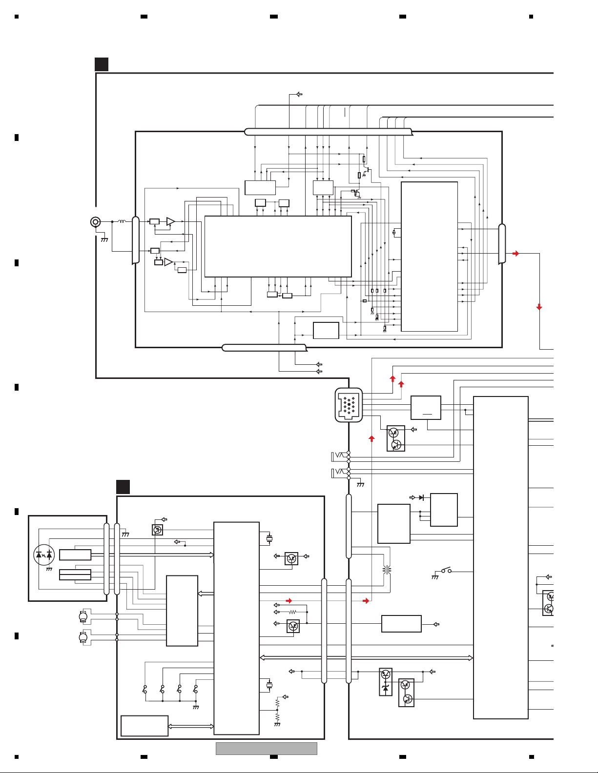
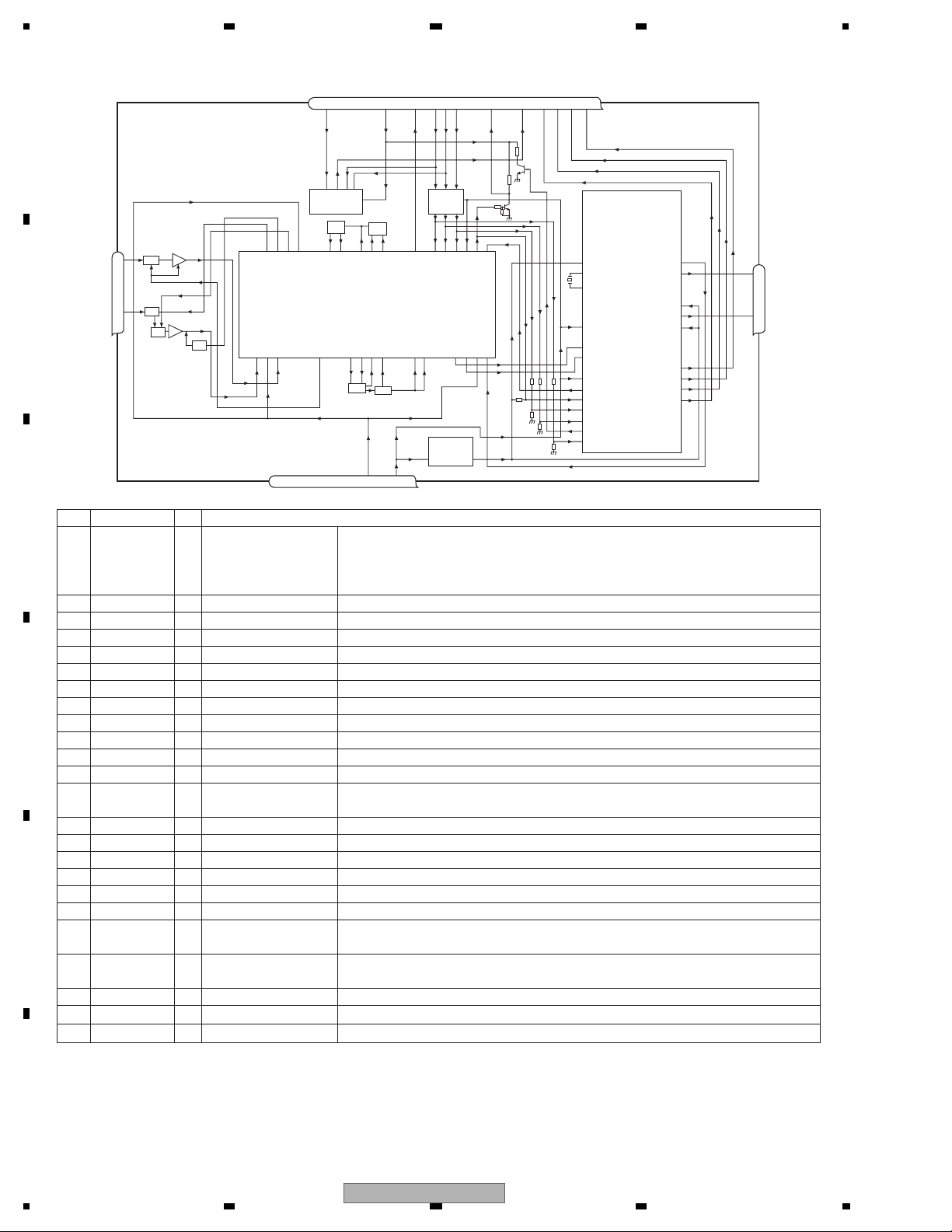
4. BLOCK DIAGRAM
A
A
TUNER AMP UNIT
FM/AM TUNER UNIT
VDD
LDET
LDET
TUNPDI
DO
RDS_CK
RDS_DATA
RDS_LOCK
TUNPCK
TUNPDO
76 13 5 1098 11 14 18192021
NC
CE2
ROM_VDD
DI
SL
CK
CE1
RDS_HSLK
B
C
D
PICKUP UNIT
(P10.5)(SERVICE)
LASER
DIODE
MONITOR
E
F
DIODE
LOAD/
ANTENNA
HOLOGRAM
UNIT
FOCUS ACT.
TRACKING ACT.
SPINDLE
MOTOR
CARRIAGE
MOTOR
VDD_3.3
5V t 3.3V
3.3V
IP-BUS
AUX
WIRE
REMOTE
VDD2
CN701
DP
DM
LOUT
VDD
/RESET
VD
IC 5
IC 4
3.3V t 2.5V
3.3V
16
17
13
9
8
2
1
CN151
USB
Rch
Lch
TX
RX
RX2
SYSTEM
CONTROLLER
IC 601(2/2)
IPPW
PEG402A8
ASENBO
KEYD
KEYAD
SYNC
USBCTL
FLG
DSENS
CDRST
VDCONT
24
23
TUNL
CDL
BUS+L
BUS-L
AUXL
AUXG
46
SYSPW
39
MUTE
48
OELPW
68
AMPPW
50
FLPILM
8
EJTIN
IL
Q8
49
ILMPW
36
DIM
VDD
47
SWVDD
33
DPDT
34
KYDT
91
CSENS
IC 2
2.5V
DET, FM MPX,
RDS DECODER
2.5V
BUSBUS+
Q101
BUP
VOUT
IC521
R5523N001B
IP-BUS DRIVER
IC101
HA12241FP
5
BUS-
6
BUS+ ROUT
STBY
BUP
4
VIN
1
EN
3
FLG
TX
1
DIN1
2
RX
8
8
IPPW
USB5V
REGULATOR
IC501
BD9781HFP
1
VIN
2
SW
5
FB
6
INV
DSENS
S801
28
27
19
52
38
32
92
7
26
EN
22
23
9
6
5
4
3
2
1
1
2
3
4
3
7
CN101
AUXL
AUXG
KEYD
KEYAD
CN521
VBUS
D-
D+
CN701
DP
DM
CDL
7
BUSL+
11
BUSL-
5
1
8
Q102
5
VDD 3.3V REGULATOR
CDVDD
CDRST
VD
3
NJM2885DL1-33
BRST,BRXEN,BSRQ,BDATA,BSCK
VD 7.5V REGULATOR
Q751
11
12
18
19
IC780
Q752
1
VDD
21
BUP
20
IC 3 EEPROM
5.0V
OSC
LPF
ANT401
1
2,3
LD-
15
MD
5
VREF
FOM
FOP
2
TOP
1
TOM
LD+
14
M
M
AM ANT
1
FM ANT
3
CD CORE UNIT(S10.5COMP2-iPod)
D
CN101
15
5
88
FOM
33
FOP
2
TOP
1
TOM
44
14
S904
12EJ
iPod CP
IC205
341S2094
Q101
ATT
ATT
ANT adj
S905
8EJ
FMRF
FMRF
RF adj
RF-AMP, CD DECODER,
MP3/WMA DECODER,
DIGITAL SERVO / DATA PROCESSOR CPU,
USB HOST CONTROLLER
CD
TD,FD
SD,MD
22
LOEJ
21
CLCONT
9
CONT
S901
HOME
CPRDY,CPRST
SDA,SCL
141
142
133
28
20
41
10
12
11
14
13
16
15
18
17
REFO
VDD2
FOM
FOP
TOP
TOM
SOP
SOM
LCOP
LCOM
AC,BD,E,F
DRIVER
IC301
BA5839FP
S903
DSCSNS
MIXER, IF AMP
RFGND
OSCGND
DGND
IC201
USBXTAL
/USBXTAL
/PUEN
LOUT
/ADENA
/RESET
XTAL
/XTAL
VDSENS
AUDIOGNDNCVCC
1
2
VCC
39
5
DP
4
DM
55
VDD
VDD2
VDD3
17
16
50
52
11
212 1522 16 4 17
LD
PD
REFOUT
PE5611B
LOEJ
CLCONT
CONT
8
12EJ
7
8EJ
DSCSNS
9
HOME
IC 1
3.3V
T51
CF52
X205
48MHz
Q102
BRST,BRXEN,BSRQ
BDATA,BSCK
VD
X201
16.93MHz
Q201
VD
16
1234
DEH-P6000UB/XN/EW5

5 678
A
Rch
24
Lch
23
SYSTEM
CONTROLLER
IC 601(2/2)
W
PEG402A8
ENBO
YD
YAD
NC
BCTL
NS
RST
CONT
SYSPW
MUTE
OELPW
AMPPW
FLPILM
EJTIN
ILMPW
SWVDD
DPDT
KYDT
CSENS
CN301
SWL
Q303
Q302
5
FL
6
CN981
BUP
16
ACC
14
ILL
12
TEL
9
GND
15
FL- FL2
7
FL+ FL1
5
RL- RL2
8
RL+ RL1
6
BEM
11
KEYBOARD UNIT
V1901
OEL UNIT
REGS
VAH
VDD
7
13
Q1902
16
6
RCA OUT
BACK
UP
ILM
GND
VKH
B.UP
B.REM
B.
REM
ACC
ACC
GND
B
ILL
TEL
C
FL-
FL+
RL-
RL+
RR
RR
+
FR
FR
+
FL
FL
+
-
D
RL
RL
+
-
E
F
ILM SENS
Q931
23
21
3
5
21
20
19
10
18
5.1V
SIRX
SCL
XCMD
XI
XRES
MUTE
B
3.3V
ILLUMI
3
1
SWL
MUTING
Q381
7
VCC
16
VREF
10
REM
12
DPDT
13
KYDT
3.3V REGULATOR
FL
VDD
MUTE
Q351
E-MUTE
Q391
IC431
NJM2885DL1-33
ROTARY COMMANDER
S1906
10
1
Phase_B
Phase_A
19
9
4
6
XIN
ROT1
ROT0
KEY/OEL CONTROLLER
PEG411A
13
X1901
10.000MHz
XOUT
IC1902
14
12
Q921
VDD REGULATOR
Q901
Q902
B SENS
A SENS
TEL MUTE
Q951
POWER AMP
IC 351
FLIN
PAL007C
RLIN
STBYMUTE
22 4
BUP
VCC
18
17
15
ADKEY2
ADKEY1
ADKEY0
6,20
VCC
B.REM
25
KEY MATRIX
S1901,S1902,S1904,
S1903,S1905,S1908,
2
DOUT
1
DCLK
20
XCMD
14
NCLK
11
XREST
BUP
BUP
FL-
FL+
RL-
RL+
S1907,S1909
S1910
BZ601
BUZZER
24
SYSTEM
IC 601(1/2)
PEG402A8
DALMON
BSENS
ASENS
1
4
1
PANEL UNIT
CN1801
ILM+
9
SWVDD
11
OPT IN
DPDT
3
KYDT
5
OEL+B
8
CSENS
10
PEE
13
XIN
X601
11
15.00MHz
XOUT
45
16
73
51
ISENS
40
TELIN
BUP
BUP
OEL14V
5.1V
IC1901
GP1UX51RK
REMOTE CONTROL
SENSOR
CE2
63
64
66
67
65
72
95
75
76
71
74
1
10
12
Pre/SW_L
10
Front_L
11
Rear_L
SYS +B REGULATOR
VCC
6,7
DC/DC CONVERTER
6
8
S1970
9
EJECT
7
2
11
14
CN1951
CN1950
TUNPCE2
TUNPCE1
TUNPDI
TUNPDO
TUNPCK
LDET
SL
RDSSDT
RDS57K
RCK
RDSSLK
RESET
2
NJM2388F84
IC561
NJM2360M
4
2
10
8
CONTROLLER
IC911
C
CE1
TUNPDI
TUNPDO
TUNPCK
LDET
SL
Q401
RDSDATA
RDSHSLK
Q402
RDSCK
RDSLOCK
RESET
2
VDD
TUNL
CDL
BUS+L
BUS-L
AUXL
AUXG
VST,VCK,VDT
46
39
48
68
BUP
50
8
ILM CONTROL
BUP
Q823
49
36
DIM
SWVDD
VDD
47
33
34
91
IC651
S-80835CNMC-B8U
ELECTRONIC VOLUME/
SOURCE SELECTOR
6
IN2_L
7
IN1_L
3
IN4+_L
IC201
4
IN4-_L
PML018A
2
IN5+_L
1
IN5-_L
Q562
CN801
FILM+
Q801
FILM-
EJSW
DGND
Q821
ILM+
Q822
SWVDD
Q891
Q892
DPDT
KYDT
OEL14V
CSENS
Q561
565
8
9
7
2
11
14
10 10 5
44 3
56
DEH-P6000UB/XN/EW5
7
8
17
1234
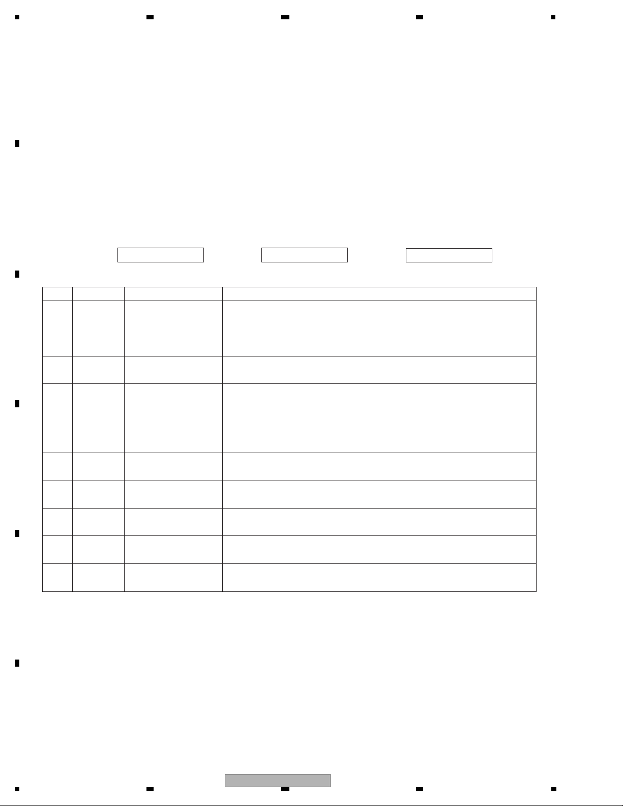
- FM/AM Tuner Unit
A
7 6 13 5 10 9 8 11 14 18 19 20 21
NC
CE2
ROM_VDD
DI
SL
CK
CE1
LDET
DO
RDS_CK
RDS_DATA
RDS_LOCK
RDS_HSLK
3.3V
IC 5
t
5V
3.3V
IC 4
t
3.3V 2.5V
2.5V
IC 2
2.5V
DET, FM MPX,
RDS DECODER
AM ANT
1
AT T
FM ANT
3
B
C
No. Symbol I/O Explain
AT T
ANT adj
FMRF
FMRF
RF adj
IC 3 EEPROM
5.0V
OSC
LPF
IC 1
3.3V
MIXER, IF AM P
T51
CF52
RFGND
OSCGND
DGND
212 1522 16 4 17
AUDIOGNDNCVCC
VDD_3.3
1 AMANT I AM antenna input AM antenna input high impedance AMANT pin is connected with
an all antenna by way of 4.7 µH. (LAU type inductor) A series circuit
including an inductor and a resistor is connected with RF ground for
the countermeasure against the hum of power transmission line.
2 RFGND RF ground Ground of antenna block
3 FMANT I FM antenna input Input of FM antenna 75 Surge absorber
(DSP-201M-S00B)is necessary.
4 VCC power supply The power supply for analog block. D.C 8.4 V ± 0.3 V
5 SL O signal level Output of FM/AM signals level
6 CE2 I chip enable-2 Chip enable for EEPROM ”Low” active
7 NC non connection Not used
D
8 CE1 I chip enable-1 Chip enable for AF•RF ”High” active
9 CK I clock Clock
10 DI I data in Data input
11 LDET O lock detector “Low” active
12 OSCGND osc ground Ground of oscillator block
13 ROM_VDD power supply Power supply for EEPROM pin 13 is connected with a power supply of
micro computer.
14 DO O data out Data output
15 DGND digital ground Ground of digital block
16 NC non connection Not used
17 VDD_3.3 power supply The power supply for digital block. 3.3 V ± 0.2 V
18 RDS_CK O RDS clock Output of RDS clock(2.5 V)
19 RDS_DATA O RDS data Output of RDS data(2.5 V)
E
20 RDS_LOCK O RDS lock Output unit “High” active(2.5 V) (RDS_LOCK turns over by the
external transistor . “Low” active)
21 RDS_HSLK O RDS high speed Output unit “High” active(2.5 V)(RDS_HSLK turns over by the
lock external transistor. “Low” active)
22 AUDIOGND audio ground Ground of audio block
23 L ch O L channel output FM stereo “L-ch” signal output or AM audio output
24 R ch O R channel output FM stereo “R-ch” signal output or AM audio output
Rch
24
Lch
23
F
18
1234
DEH-P6000UB/XN/EW5
5 678
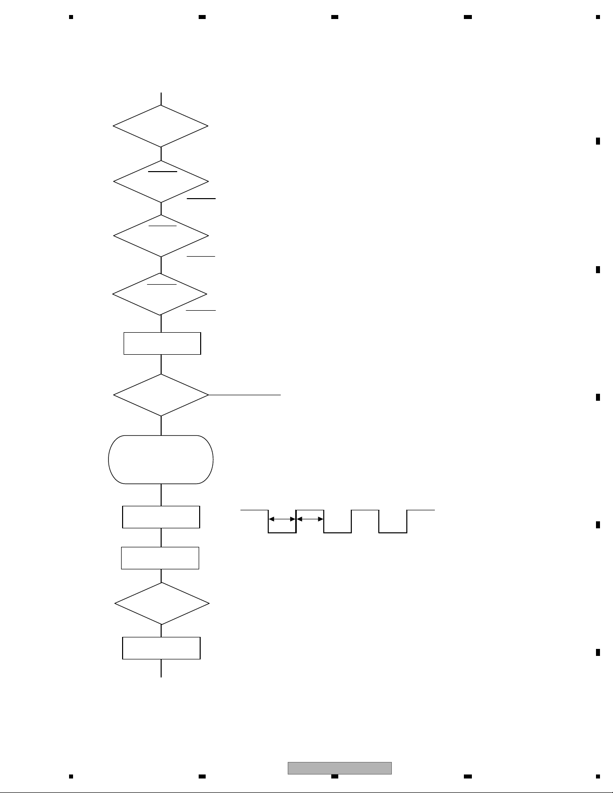
5. DIAGNOSIS
5.1 OPERATIONAL FLOWCHART
Power ON
Vcc = 5 V
Pin14
BSENS
Pin16
BSENS = L
ASENS
Pin73
ASENS = L
DSENS
Pin9
DSENS = L
A
B
ASENBO<-H
Pin38
CSENS
Pin91
2 V < CSENS < 3 V
Starts
communication
with Grille
microcomputer.
SWVDD<-H
Pin47
Source keys
operative
Source ON
C
- 2 V < CSENS < 3 V
Last source returns.
CD loading functions are available.
Keys except for EJECT key are not available.
D
300 ms
300 ms
In case of the above signal, the communication
with Grille microcomputer may fail.
If the time interval is not 300 msec, the oscillator
may be defective.
E
SYSPW<-H
Pin46
Completes power-on operation.
(After that, proceed to each source operation)
DEH-P6000UB/XN/EW5
56
F
7
8
19
1234
5.2 ERROR CODE LIST
- CD Error Messages
A
If a CD is not operative or stopped during operation due to an error, the error mode is turned on and cause(s) of
the error is indicated with a corresponding number. This arrangement is intended at reducing nonsense calls from
the users and also for facilitating trouble analysis and repair work in servicing.
(1) Basic Indication Method
1) When SERRORM is selected for the CSMOD (CD mode area for the system), error codes are written to DMIN
(minutes display area) and DSEC (seconds display area). The same data is written to DMIN and DSEC. DTNO
remains in blank as before.
B
Depending on display capability of LCD used, display will vary as shown below. xx contains the error number.
8-digit display 6-digit display 4-digit display
ERROR-xx ERR-xx E-xx
(2) Error Code List
2) Head unit display examples
Code
10
C
Class Displayed error code Description of the code and potential cause(s)
Electricity Carriage Home NG CRG can't be moved to inner diameter.
SERVO LSI Com-
CRG can't be moved from inner diameter.
munication Error → Failure on home switch or CRG move mechanism.
Communication error between microcomputer and SERVO LSI.
11 Electricity Focus Servo NG Focusing not available.
→ Stains on rear side of disc or excessive vibrations on REWRITABLE.
12 Electricity Spindle Lock NG Spindle not locked. Sub-code is strange (not readable).
Subcode NG → Failure on spindle, stains or damages on disc, or excessive vibrations.
A disc not containing CD-R data is found.
Turned over disc are found, though rarely.
CD signal error.
D
17 Electricity Setup NG AGC protection doesn't work. Focus can be easily lost.
→ Damages or stains on disc, or excessive vibrations on REWRITABLE.
30 Electricity Search Time Out Failed to reach target address.
→ CRG tracking error or damages on disc.
44 Electricity ALL Skip Skip setting for all track.
(CD-R/RW)
50
Mechanism
CD On Mech Error Mechanical error during CD ON.
→ Defective loading motor, mechanical lock and mechanical sensor.
A0 System Power Supply NG Power (VD) is ground faulted.
→ Failure on SW transistor or power supply (failure on connector).
E
Remarks: Mechanical errors are not displayed (because a CD is turned o in these errors).
Unreadable TOC does not constitute an error. An intended operation continues in this case.
Upper digits of an error code are subdivided as shown below:
1x: Setup relevant errors, 3x: Search relevant errors, Ax: Other errors.
F
20
1234
DEH-P6000UB/XN/EW5

5 678
iPod error
STOP
ERROR-11
ERROR-21
ERROR-A0
USB error
NO AUDIO
TRK SKIPPED
PROTECT
N/A USB
CHK USB
No songs in the current list
Communication failure
Old version of the iPod
iPod is not charged but operates
correctly.
No songs in the USB device
USB memory with security enabled is
connected
The connected USB device contains
WMA files that are protected by DRM
All the files in the USB device are
protected by DRM
The connected USB device is not
supported by this unit
The USB connector or the USB cable is
short-circuited
The connected USB device consumes
more than 500 mA
(max. allowable current)
Selected m3u playlist cannot be played
back
All the files on the selected m3u playlist
are protected by DRM
ActionCauseMessage
Transfer the songs to the iPod.No songs in the iPodNO SONGS
Select a list that contains the songs.
Disconnect the cable from the iPod. Once the iPod
main menu is displayed, connect the cable again.
Reset the iPod.
Update the iPod version.
Reset the iPod.iPod failureERROR-30
Check if the connection cable for the iPod shorted out.
After checking, switch the ignition key or disconnect the
iPod and connect again.
ActionCauseMessage
Transfer the songs to the USB device.
Follow the USB memory instructions to disable the
security.
Play an audio file not protected by DRM.
Transfer the songs not protected by DRM to the USB
device.
Connect a USB device that is compliant as a Mass
Storage Class.
Confirm the USB connector or the USB cable.
Confirm the USB device.
Select another playlist.N/A PLAYLIST
A
B
C
D
56
DEH-P6000UB/XN/EW5
E
F
7
8
21

1234
5.3 CONNECTOR FUNCTION DESCRIPTION
A
1. BUS+
2. GND
3. GND
IP-BUS INPUT
4. NC
5. BUS-
6. GND
7. BUS L+
111098
765
4321
8. ASENB
SUBWOOFER
OUTPUT
B
C
FRONT
OUTPUT
ANTENNA
9. BUS R+
10. BUS R-
11. BUS L-
USB
AUX IN
AUX IN
W/R
WIRED REMOTE INPUT
9
7
5
3
1
8
6
4
2
1 FR+
2 RR+
3 FR4 RR-
D
5 FL+
6 RL+
7 FL8 RL-
E
11
10
12
9 MUTE
10 NC
11 B.REM
12 ILM
13 NC
14 ACC
15 GND
16 B.UP
13 15
14 16
F
22
1234
DEH-P6000UB/XN/EW5
5 678
6. SERVICE MODE
6.1 CD TEST MODE
During pressing the "SOURCE" and "RPT" keys simultaneously, perform the reset-start, then turn ON
the CD to enter the CDS test mode.
• How to issue the 1 - 6 keys in the 08 model's slave test:
The specification of the 08 model does not include the 1 - 6 keys issuance function for H/U and the remote control unit.
Therefore, in order to issue commands in a slave test, use the direct FUNCTION keys alternatively to enable the equal
key command sending function to the existing models.
Outline) Use the direct FUNCTION keys to display, select, or issue the KEY 1 - 6.
<Direct FUNCTION keys and corresponding functions>
Direct FUNCTION key Normal mode Slave test mode
A Selecting a key command
B
C Switching a screen
S.Rtrv
RDM Issuing a key command
RPT
• For convenience, a name of each direct FUNCTION key is shown as "A", "B", and "C".
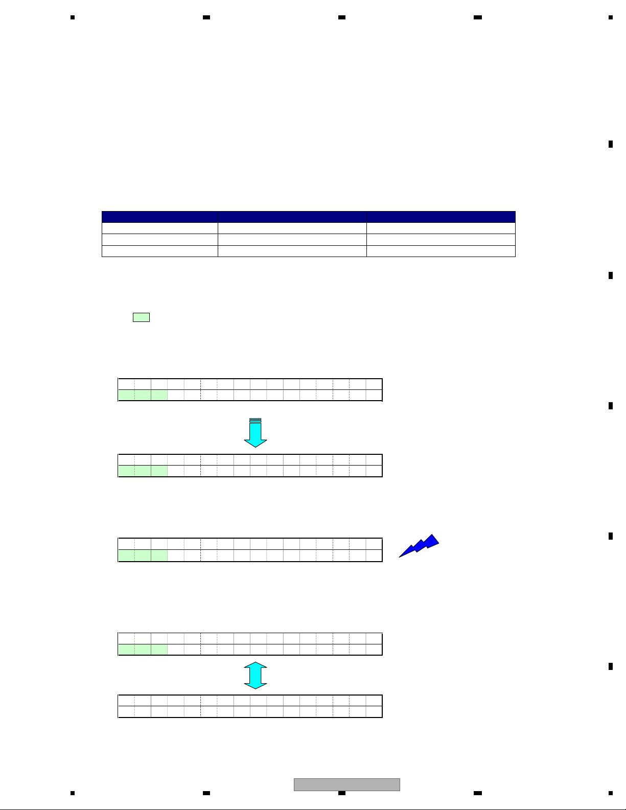
• How to issue the 1 - 6 keys for the CDS source:
(The areas below are overwritten and displayed on character strings for the normal mode display.)
1 During the slave test mode, the key name "K1" is shown at the left by default.
In this condition, press the A key to toggle K1 - K6, and select a command to be sent to the slave.
A
B
C
COMPACT D I S C
K1 ! T -!! !!!!
• The one-line model shows only the bottom
column.
DNOCESETUNIMKRTREDLOF
A key
COMPACT D I S C
K6 T
! -!! !!!!
2 During the K1 - K6 key names are displayed, press the B key and issue the selected command.
COMPACT D I S C
K1 T
! -!! !!!!
Send a key command selected
by pressing the KEY 1.
B key
3 Press the C key to change display/non-display of key names.
When the non-display mode is selected for the K1 - K6 key names, "A key" and "B key" are invalid.
COMPACT D I S C
K1 T
! -!! !!!!
C key
D
E
COMPACT D I S C
F -! T
! -!! !!!!
DEH-P6000UB/XN/EW5
56
• Pressing the A key or B key does not work.
7
8
F
23
Loading...