


DEHP-545
Pioneer DEHP-545, DEHP-56, DEHP-645, DEH-41, DEH-445 Service manual
...
MULTI-CD CONTROL HIGH POWER CD PLAYER WITH ID-LOGIC TUNER
DEH-P645 UC
Se
r
vic
e
M
a
nu
a
l
DEH-P56 UC
DEH-P545 UC
DEH-46 UC
DEH-445 UC
DEH-41 UC
DEH-P645/UC
PIONEER ELECTRONIC CORPORATION 4-1, Meguro 1-Chome, Meguro-ku, Tokyo 153-8654, Japan
PIONEER ELECTRONICS SERVICE INC. P.O.Box 1760, Long Beach, CA 90801-1760 U.S.A.
PIONEER ELECTRONIC [EUROPE] N.V. Haven 1087 Keetberglaan 1, 9120 Melsele, Belgium
PIONEER ELECTRONICS ASIACENTRE PTE.LTD. 501 Orchard Road, #10-00, Lane Wheelock Place, Singapore 23880
C PIONEER ELECTRONIC CORPORATION 1998
ORDER NO.
CRT2147
CONTENTS
1. SAFETY INFORMATION ............................................2
2. EXPLODED VIEWS AND PARTS LIST.......................3
3. SCHEMATIC DIAGRAM ...........................................12
4. PCB CONNECTION DIAGRAM ................................40
5. ELECTRICAL PARTS LIST ........................................50
6. ADJUSTMENT..........................................................75
7. GENERAL INFORMATION .......................................81
7.1 PARTS .................................................................81
7.1.1 IC................................................................81
7.1.2 DISPLAY....................................................88
7.2 DIAGNOSIS ........................................................89
7.2.1 DISASSEMBLY .........................................89
7.2.2 TEST MODE..............................................90
7.3 BLOCK DIAGRAM ..............................................92
8. OPERATIONS AND SPECIFICATIONS.....................94
- See the separate manual CX-597(CRT1829) for the CD mechanism description, disassembly and circuit
description.
- The CD mechanism employed in this model is one of S7 series.
K-FEA. FEB. 1998 Printed in Japan

2
DEH-P645,P56,P545,46,445,41
- CD Player Service Precautions
1. For pickup unit(CXX1230) handling, please refer
to"Disassembly"(CX-597 Service Manual CRT1829).
During replacement, handling precautions shall be
taken to prevent an electrostatic discharge(protection
by a short pin).
2. During disassembly, be sure to turn the power off
since an internal IC might be destroyed when a connector is plugged or unplugged.
3. Please checking the grating after changing the service pickup unit(see page 79).
CAUTION
This service manual is intended for qualified service technicians; it is not meant for the casual do-it-yourselfer.
Qualified technicians have the necessary test equipment and tools, and have been trained to properly and safely repair
complex products such as those covered by this manual.
Improperly performed repairs can adversely affect the safety and reliability of the product and may void the warranty.
If you are not qualified to perform the repair of this product properly and safely; you should not risk trying to do so and
refer the repair to a qualified service technician.
W
ARNING
Lead in solder used in this product is listed by the California Health and Welfare agency as a known reproductive toxicant which may cause birth defects or other reproductive harm (California Health and Safety Code, Section 25249.5).
When servicing or handling circuit boards and other components which contain lead in solder, avoid unprotected skin
contact with the solder. Also, when soldering do not inhale any smoke or fumes produced.
1. SAFETY INFORMATION
3
DEH-P645,P56,P545,46,445,41
5
9
15
4
14
16
21
20
22
19
17
18
23
13
12
1
2
11
8
6
7
10
3
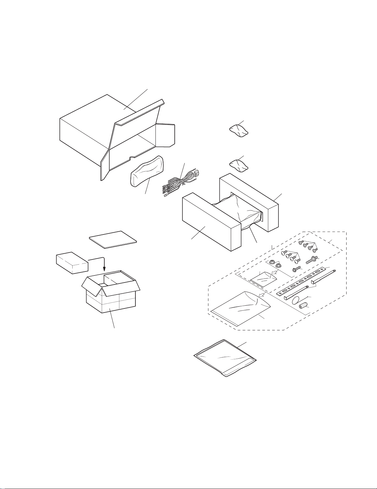
Fig. 1
2. EXPLODED VIEWS AND PARTS LIST
2.1 PACKING
4
DEH-P645,P56,P545,46,445,41
- PACKING SECTION PARTS LIST
(1) PARTS LIST
Mark No. Description Part No.
Mark No. Description Part No.
NOTE:
- Parts marked by "*"are generally unavailable because they are not in our Master Spare Parts List.
- Screws adjacent to
∇ mark on the product are used for disassembly.
* 1-1 Card
See Contrast table(2)
1-2 Polyethylene Bag CEG1116
1-3 Owner's Manual
See Contrast table(2)
1-4 Installation Manual See Contrast table(2)
* 1-5 Warranty Card See Contrast table(2)
1-6 Caution Card See Contrast table(2)
2 Cord Assy See Contrast table(2)
3 Accessory Assy CEA1918
4 Spring CBH-865
5 Screw Assy CEA1924
6 Screw CBA-102
7 Screw CBA1284
* 8 Polyethylene Bag CNM4338
9 Screw CRZ50P090FMC
10 Nut NF50FMC
11 Screw TRZ50P080FMC
* 12 Polyethylene Bag CEG-158
13 Handle CNC5395
14 Strap CNF-111
15 Bush CNV1009
16 Polyethylene Bag CEG1173
17 Battery
See Contrast table(2)
18 Carton See Contrast table(2)
19 Contain Box See Contrast table(2)
20 Protector CHP1766
21 Protector CHP1767
22 Case Assy CXB1063
23 Remote Control Unit
See Contrast table(2)
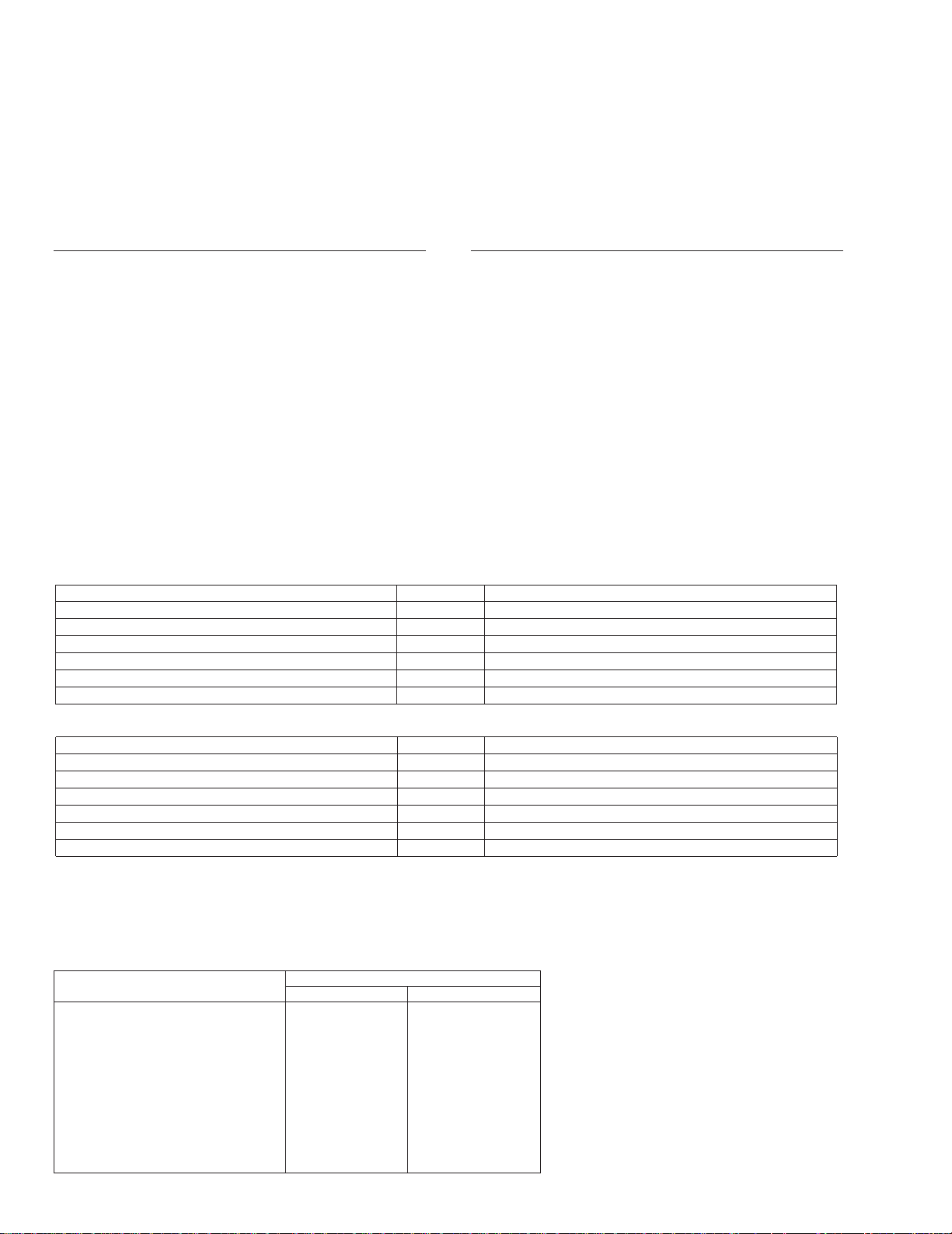
- Owner’s Manual
Model Part No. Language
DEH-P645/UC CRD2555 English, French
DEH-P56/UC CRD2564 English, French
DEH-P545/UC CRD2566 English, French, Spanish
DEH-46/UC CRD2572 English, French, Spanish
DEH-445/UC CRD2574 English, French, Spanish
DEH-41/UC CRD2576 English, French, Spanish
- Installation Manual
Model Part No. Language
DEH-P645/UC CRD2556 English, French
DEH-P56/UC CRD2565 English, French
DEH-P545/UC CRD2567 English, French, Spanish
DEH-46/UC CRD2573 English, French, Spanish
DEH-445/UC CRD2575 English, French, Spanish
DEH-41/UC CRD2577 English, French, Spanish
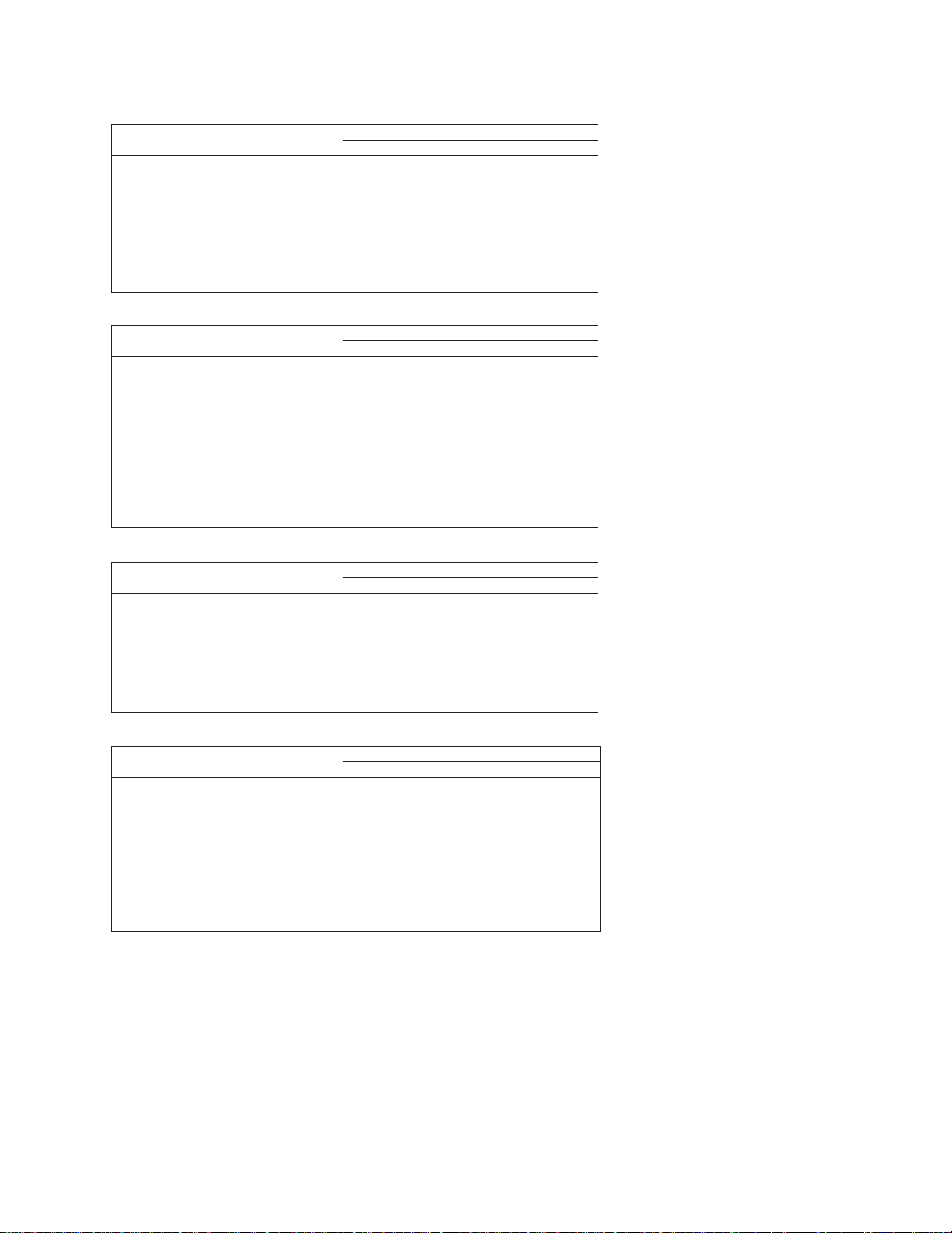
Part No.
Mark No. Symbol and Description DEH-P645/UC DEH-P56/UC
* 1-1 Card ARY1048 Not used
1-3 Owner's Manual CRD2555 CRD2564
1-4 Installation Manual CRD2556 CRD2565
* 1-5 Warranty Card Not used CRY1070
1-6 Caution Card CRP1182 Not used
17 Battery CEX1030 Not used
18 Carton CHG3435 CHG3439
19 Contain Box CHL3435 CHL3439
23 Remote Control Unit CXB1225 Not used
(2) CONTRAST TABLE
DEH-P645/UC, DEH-P56/UC, DEH-P545/UC, DEH-46/UC, DEH-445/UC and DEH-41/UC are constructed
same except for the following:
DEH-P645,P56,P545,46,445,41
Part No.
Mark No. Symbol and Description DEH-P645/UC DEH-P545/UC
1-3 Owner's Manual CRD2555 CRD2566
1-4 Installation Manual CRD2556 CRD2567
1-6 Caution Card CRP1182 Not used
17 Battery CEX1030 Not used
18 Carton CHG3435 CHG3438
19 Contain Box CHL3435 CHL3438
23 Remote Control Unit CXB1225 Not used
Part No.
Mark No. Symbol and Description DEH-P645/UC DEH-46/UC
* 1-1 Card ARY1048 Not used
1-3 Owner's Manual CRD2555 CRD2572
1-4 Installation Manual CRD2556 CRD2573
* 1-5 Warranty Card Not used CRY1070
1-6 Caution Card CRP1182 Not used
17 Battery CEX1030 Not used
18 Carton CHG3435 CHG3443
19 Contain Box CHL3435 CHL3443
23 Remote Control Unit CXB1225 Not used
Part No.
Mark No. Symbol and Description DEH-P645/UC DEH-445/UC
1-3 Owner's Manual CRD2555 CRD2574
1-4 Installation Manual CRD2556 CRD2575
17 Battery CEX1030 Not used
18 Carton CHG3435 CHG3444
19 Contain Box CHL3435 CHL3444
23 Remote Control Unit CXB1225 Not used
Part No.
Mark No. Symbol and Description DEH-P645/UC DEH-41/UC
1-3 Owner's Manual CRD2555 CRD2576
1-4 Installation Manual CRD2556 CRD2577
1-6 Caution Card CRP1182 Not used
2 Cord Assy CDE5483 CDE5484
17 Battery CEX1030 Not used
18 Carton CHG3435 CHG3445
19 Contain Box CHL3435 CHL3445
23 Remote Control Unit CXB1225 Not used
5
6
DEH-P645,P56,P545,46,445,41
Fig. 2
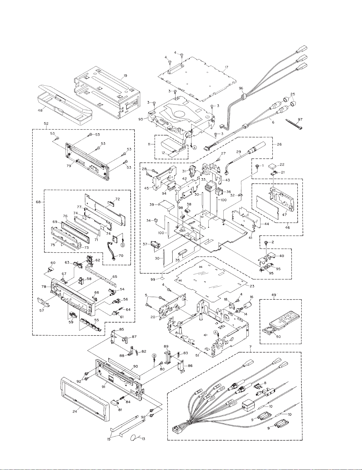
2.2 EXTERIOR

7
DEH-P645,P56,P545,46,445,41
1 Screw ASZ26P055FUC
2 Screw ASZ26P080FMC
3 Screw BSZ26P050FMC
4 Screw BSZ30P060FMC
5 Screw BSZ30P180FMC
6 Cord Assy
See Contrast table(2)
7 Cord Assy See Contrast table(2)
8 Fuse CEK1136
9 Cap CNS1472
10 Resistor RS1/2PMF102J
11 Cable CDE5635
12 Insulator CNM5761
13 Spring CBH-865
14 Screw CBA1284
15 Handle CNC5395
16 Bush CNV1009
17 Case CNB2119
18 Holder CNC4963
19 Holder CNC6798
20 Holder CNC6862
21 Earth Terminal CNC7358
22 Spacer CNM4913
23 Insulator CNM5535
24 Panel CNS4200
25 Cap
See Contrast table(2)
26 Tuner Amp Unit See Contrast table(2)
27 Screw BPZ26P080FMC
28 Screw BSZ26P140FMC
29 Antenna Cord CDH1234
30 Clamper CEF1009
31 Pin Jack(CN253) CKB1028
32 Terminal(CN501) CKF1059
33 Plug(CN901) CKM1278
34 Plug(CN802) CKS-783
35 Connector(CN651) CKS2228
36 Connector(CN101)
See Contrast table(2)
37 Connector(CN801) CKS3581
38 Connector(CN255)
See Contrast table(2)
39 Holder CNC5968
40 Holder CNC6132
41 Holder CNC6356
42 Holder CNC7429
43 Holder
See Contrast table(2)
44 Insulator CNM4684
45 Heat Sink CNR1458
46 FM/AM Tuner Unit CWE1417
47 Holder CNC6555
48 Case Assy CXB1063
49 Remote Control Unit
See Contrast table(2)
50 Cover See Contrast table(2)
51 Chassis Unit See Contrast table(2)
52 Detach Grille Assy See Contrast table(2)
53 Screw BPZ20P100FZK
54 Button CAC5397
55 Button CAC5398
56 Button CAC5399
57 Button CAC5402
58 Button CAC5403
59 Button CAC5404
60 Button CAC5405
61 Button CAC5430
62 Button CAC5450
63 Button CAC5451
64 Spring CBH2103
65 Cover CNM4704
66 Lighting Conductor CNV5180
67 Lighting Conductor CNV5181
68 Keyboard Unit
See Contrast table(2)
69 LCD See Contrast table(2)
70 Cord CDE5665
71 EL CEL1536
72 Connector(CN1801) CKS3580
73 Holder CNC7435
74 Film CNM4349
75 Spacer CNM5449
76 Connector CNV5182
77 Housing CNV5183
78 Grille Unit
See Contrast table(2)
79 Cover Unit CXB2480
80 Screw BPZ20P060FMC
81 Button CAC5180
82 Spring CBH1834
83 Spring CBH1835
84 Spring CBH1996
85 Bracket CNC6135
86 Bracket CNC6791
87 Arm CNV4692
88 Arm CNV4693
89 Arm CNV4951
90 Cover CNM4875
- EXTERIOR SECTION PARTS LIST
(1) PARTS LIST
Mark No. Description Part No.
Mark No. Description Part No.
8
DEH-P645,P56,P545,46,445,41
91 Panel See Contrast table(2)
92 Screw IMS20P030FZK
93 CD Mechanism Module CXK5004
94 IC(IC201)
See Contrast table(2)
95 Transistor(Q951, 971) 2SD2396
96 Cord Assy
See Contrast table(2)
97 Lock Tie See Contrast table(2)
98 Connector(CN851) See Contrast table(2)
99 Spacer CNM5875
100 Clamper
See Contrast table(2)
Mark No. Description Part No.
Part No.
Mark No. Symbol and Description DEH-P645/UC DEH-P56/UC
6 Cord Assy CDE5208 CDE5210
25 Cap CNV2680(×2) CNV2680(×4)
26 Tuner Amp Unit CWM5620 CWM5625
38 Connector CKS3598(CN255) CKS3602(CN251)
43 Holder CNC7432 CNC7431
49 Remote Control Unit CXB1225 Not used
50 Cover CNS4139 Not used
51 Chassis Unit CXB1983 CXB1982
52 Detach Grille Assy CXB1994 CXB2000
68 Keyboard Unit CWM5634 CWM5636
69 LCD CAW1479 CAW1459
78 Grille Unit CXB1968 CXB1973
96 Cord Assy Not used CDE5184
* 97 Lock Tie Not used CNV-754
98 Connector(CN851) Not used CKS3597
100 Clamper Not used CEF1009
Part No.
Mark No. Symbol and Description DEH-P645/UC DEH-P545/UC
26 Tuner Amp Unit CWM5620 CWM5626
49 Remote Control Unit CXB1225 Not used
50 Cover CNS4139 Not used
52 Detach Grille Assy CXB1994 CXB2001
68 Keyboard Unit CWM5634 CWM5636
69 LCD CAW1479 CAW1459
78 Grille Unit CXB1968 CXB1974
(2) CONTRAST TABLE
DEH-P645/UC, DEH-P56/UC, DEH-P545/UC, DEH-46/UC, DEH-445/UC and DEH-41/UC are constructed
same except for the following:
9
DEH-P645,P56,P545,46,445,41
Part No.
Mark No. Symbol and Description DEH-P645/UC DEH-46/UC
6 Cord Assy CDE5208 CDE5210
25 Cap CNV2680(×2) CNV2680(×4)
26 Tuner Amp Unit CWM5620 CWM5627
36 Connector(CN101) CKS3408 Not used
38 Connector CKS3598(CN255) CKS3602(CN251)
43 Holder CNC7432 CNC7431
49 Remote Control Unit CXB1225 Not used
50 Cover CNS4139 Not used
51 Chassis Unit CXB1983 CXB1988
52 Detach Grille Assy CXB1994 CXB2003
68 Keyboard Unit CWM5634 CWM5640
78 Grille Unit CXB1968 CXB1976
91 Panel CNS4451 CNS4450
94 IC(IC201) TDA7386 TDA7384
96 Cord Assy Not used CDE5184
* 97 Lock Tie Not used CNV-754
98 Connector(CN851) Not used CKS3597
100 Clamper Not used CEF1009
Part No.
Mark No. Symbol and Description DEH-P645/UC DEH-445/UC
26 Tuner Amp Unit CWM5620 CWM5628
36 Connector(CN101) CKS3408 Not used
49 Remote Control Unit CXB1225 Not used
50 Cover CNS4139 Not used
51 Chassis Unit CXB1983 CXB1989
52 Detach Grille Assy CXB1994 CXB2004
68 Keyboard Unit CWM5634 CWM5640
78 Grille Unit CXB1968 CXB1977
91 Panel CNS4451 CNS4450
94 IC(IC201) TDA7386 TDA7384
Part No.
Mark No. Symbol and Description DEH-P645/UC DEH-41/UC
6 Cord Assy CDE5208 Not used
7 Cord Assy CDE5483 CDE5484
25 Cap CNV2680 Not used
26 Tuner Amp Unit CWM5620 CWM5629
36 Connector(CN101) CKS3408 Not used
38 Connector(CN255) CKS3598 Not used
43 Holder CNC7432 CNC7434
49 Remote Control Unit CXB1225 Not used
50 Cover CNS4139 Not used
51 Chassis Unit CXB1983 CXB1989
52 Detach Grille Assy CXB1994 CXB2005
68 Keyboard Unit CWM5634 CWM5640
78 Grille Unit CXB1968 CXB1978
91 Panel CNS4451 CNS4869
94 IC(IC201) TDA7386 TDA7384
10
DEH-P645,P56,P545,46,445,41
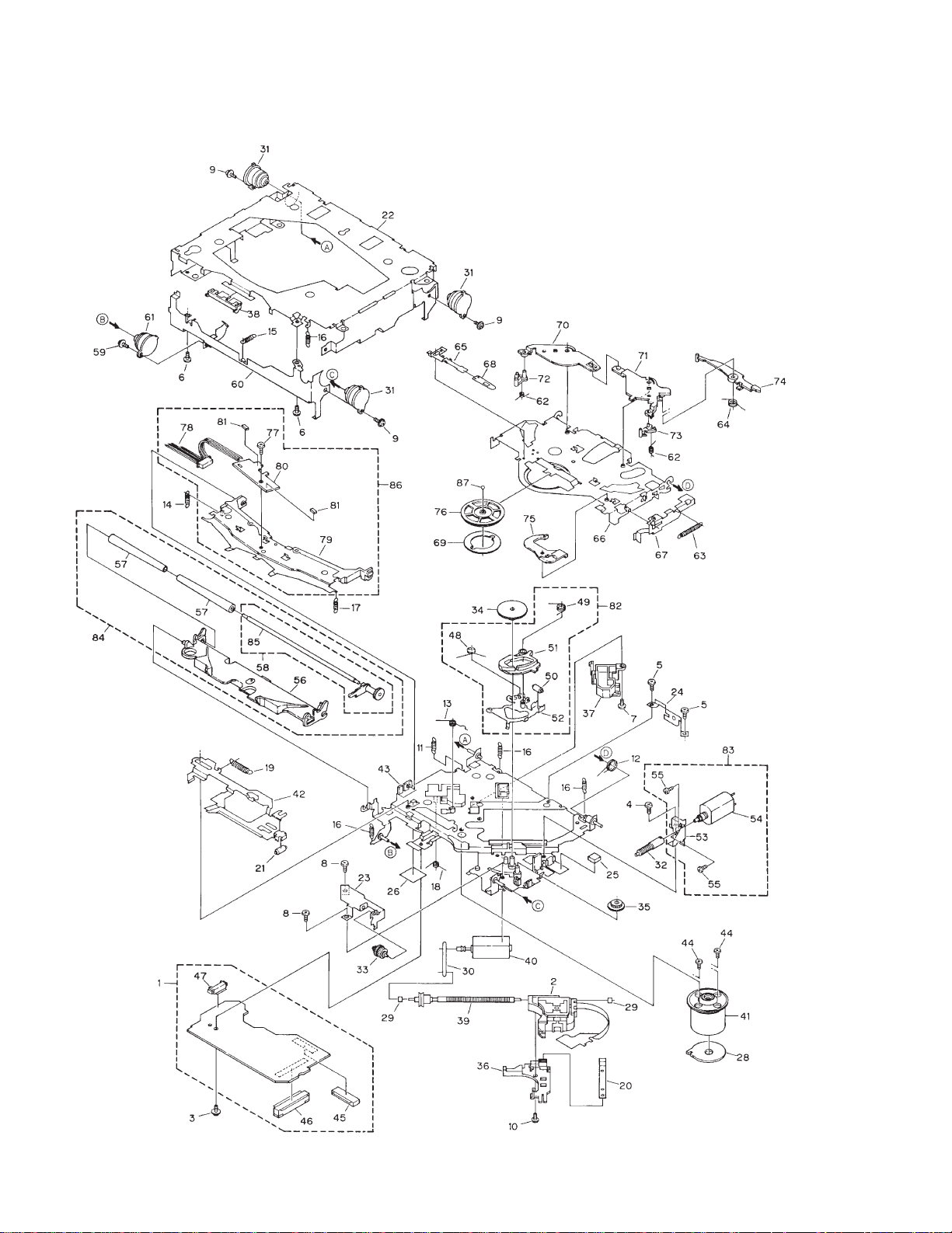
2.3 CD MECHANISM MODULE
Fig. 3

11
DEH-P645,P56,P545,46,445,41
- CD MECHANISM MODULE SECTION PARTS LIST
1 Control Unit CWX2224
2 Pickup Unit(Service) CXX1230
3 Screw IMS26P035FMC
4 Screw BMZ20P025FMC
5 Screw BMZ20P040FMC
6 Screw BSZ20P040FMC
7 Screw CBA1077
8 Screw CBA1250
9 Screw CBA1296
10 Screw CBA1362
11 Spring CBH1724
12 Spring CBH1729
13 Spring CBH1730
14 Spring CBH1731
15 Spring CBH1732
16 Spring CBH1745
17 Spring CBH1848
18 Spring CBH1849
19 Spring CBH1939
20 Spring CBL1214
21 Roller CLA2627
22 Frame CNC5796
23 Bracket CNC5871
* 24 Bracket CNC6376
25 Cushion CNM3917
26 Sheet CNM4873
27 •••••
28 PCB CNP4230
29 Bearing CNR1415
30 Belt CNT1071
31 Damper CNV3974
32 Gear CNV4128
33 Gear CNV4129
34 Gear CNV4130
35 Gear CNV4131
36 Holder CNV4663
37 Holder CNV5071
38 Guide CNV4484
39 Screw Unit(S7) CXA8699
40 CRG Motor Unit(S7) CXA8986
41 Motor Unit CXA8912
42 Lever Unit CXA9300
43 Chassis Unit CXB2574
44 Screw JFZ20P025FMC
45 Connector(CN101) CKS1953
46 Connector(CN701) CKS2774
47 Connector(CN801) CKS2196
48 Spring CBH1832
49 Spring CBH1833
50 Roller CLA2627
51 Arm CNV4136
52 Arm Unit CXA8565
53 Bracket CNC6056
54 Load Motor Unit(S7) CXA8702
55 Screw JFZ20P025FMC
56 Arm CNV4120
57 Roller CNV4509
58 Gear Unit(S7) CXA8701
59 Screw CBA1296
60 Frame CNC5797
61 Damper CNV3974
62 Spring CBH1736
63 Spring CBH1863
64 Spring CBH1945
65 Spring CBL1269
66 Arm CNC5799
67 Lever CNC6054
68 Spacer CNM3315
69 Sheet CNM4849
70 Arm CNV5436
71 Arm CNV4123
72 Arm CNV4124
73 Arm CNV4125
74 Arm CNV4138
75 Arm CNV4139
76 Clamper CNV5308
77 Screw CBA1250
78 Connector(CN1) CDE4576
79 Arm CNC7383
* 80 Gathering PCB CNX2445
81 Photo-transistor(Q1, 2) CPT-230S-X
82 ELBO Arm Assy(S7) CXA8889
83 Load Motor Assy(S7) CXA8891
84 LO Arm Assy(S7) CXA8892
85 Shaft CLA3133
86 Guide Arm Assy(S7) CXB1850
87 Ball CNR1189
Mark No. Description Part No. Mark No. Description Part No.
F
C
B
A
D E
12
DEH-P645,P56,P545,46,445,41
1
23
4
1234
D
C
B
A
A
A-a A-b
A-a
A-b
A-b
A-a
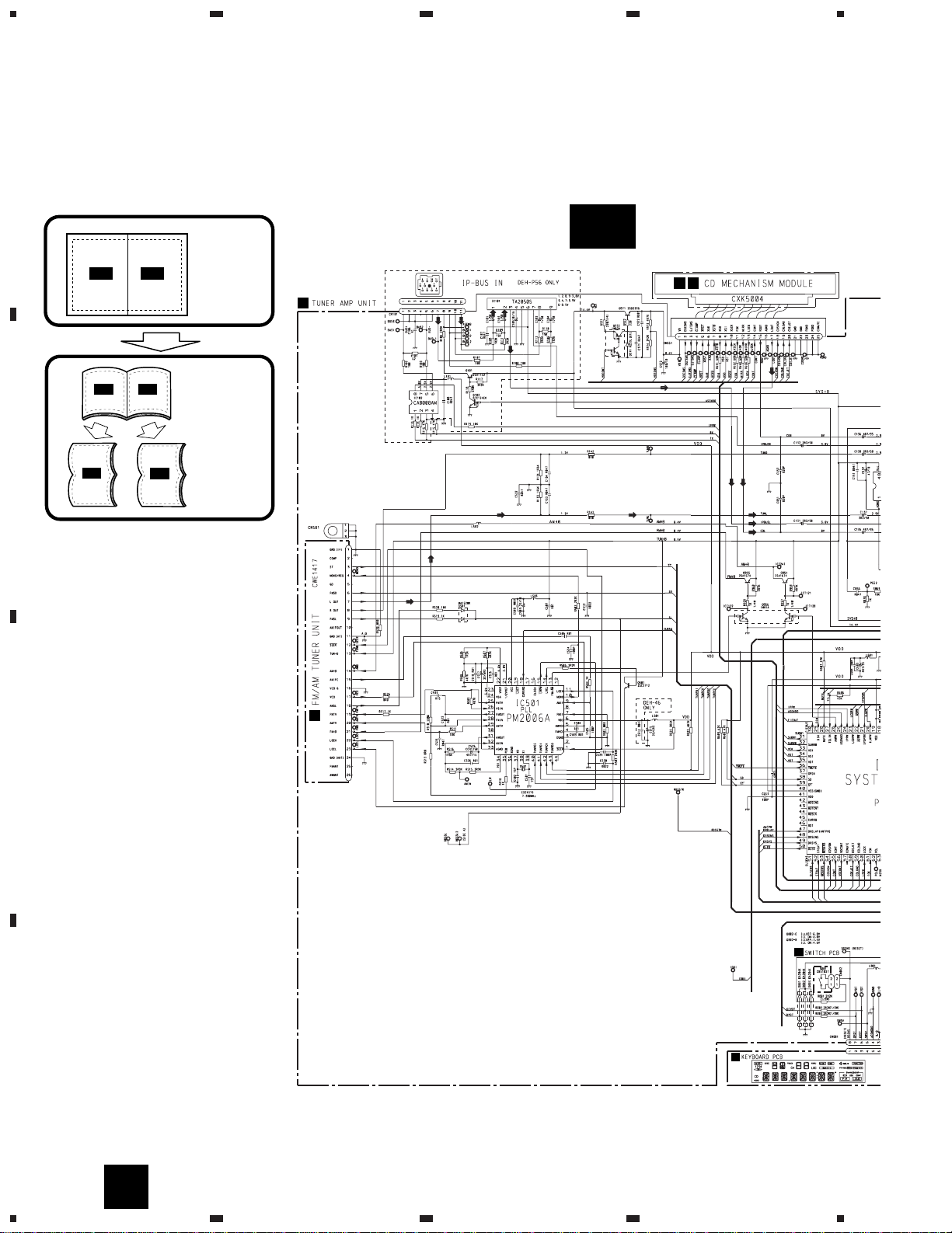
Large size
SCH diagram
Guide page
Detailed page
A-a
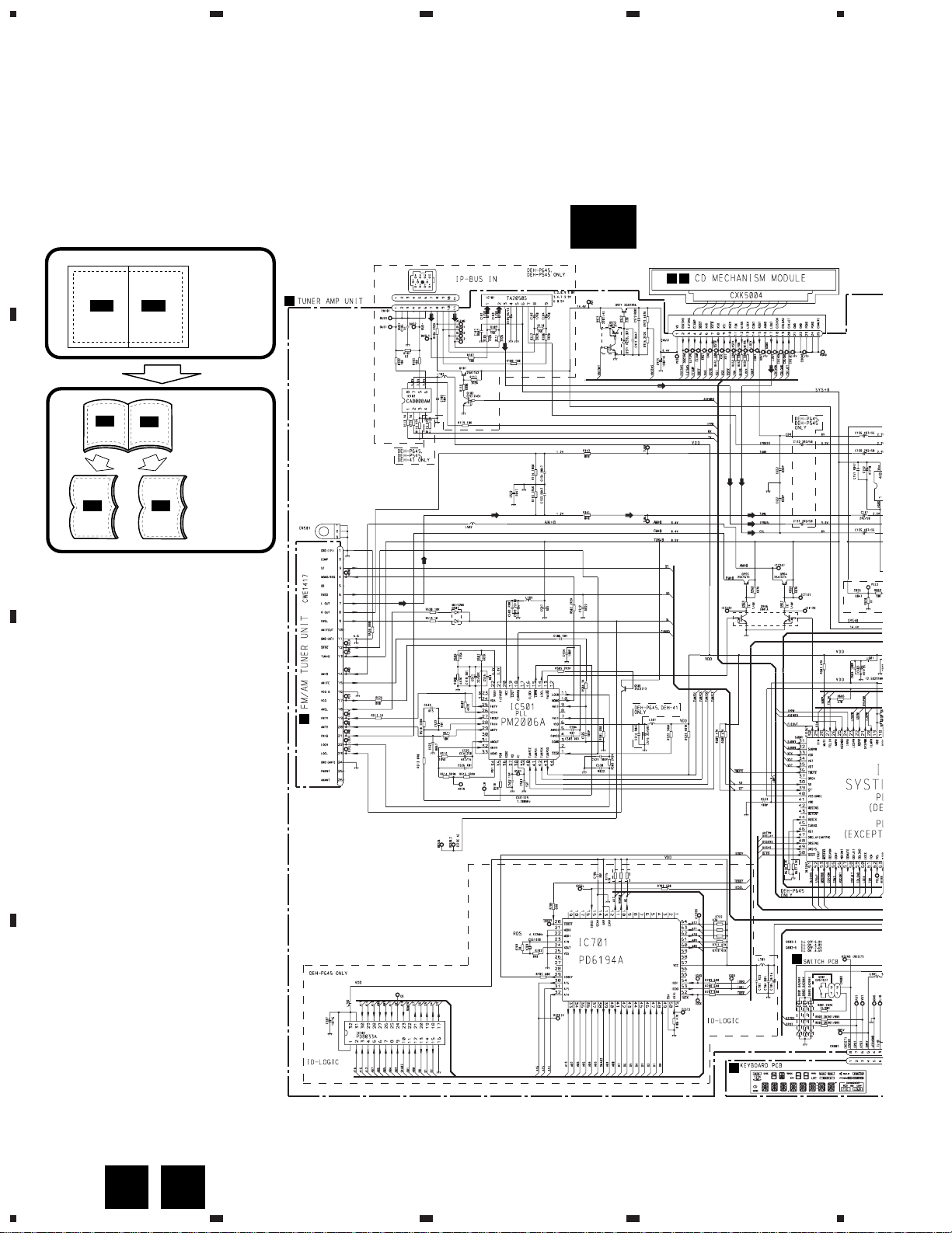
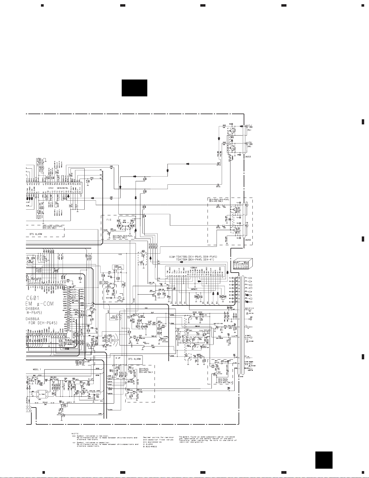
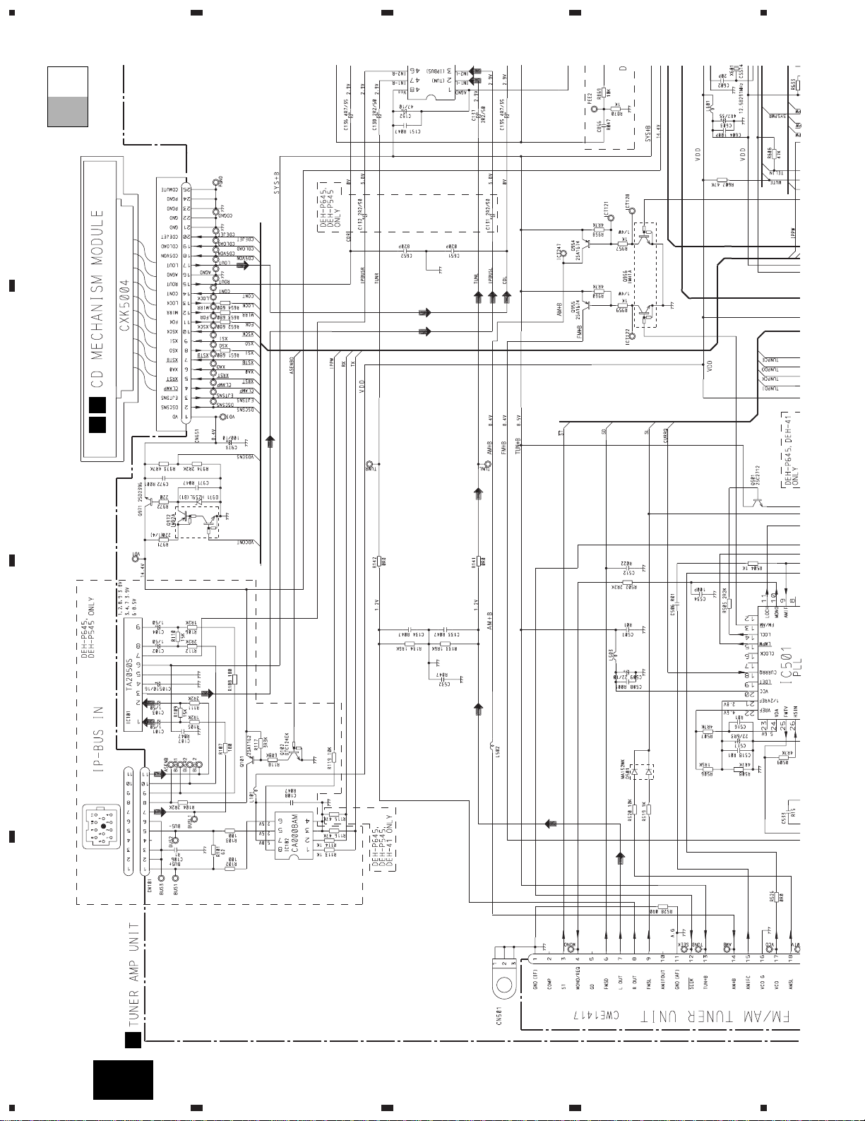
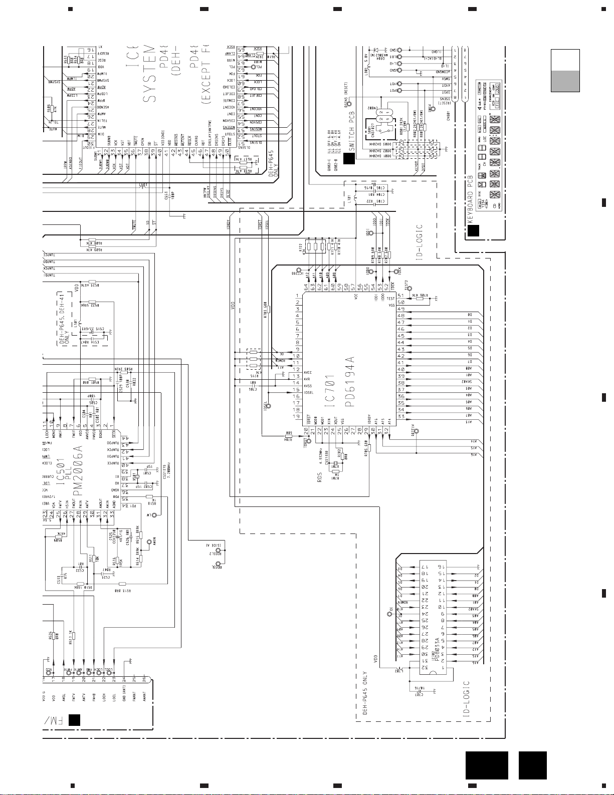
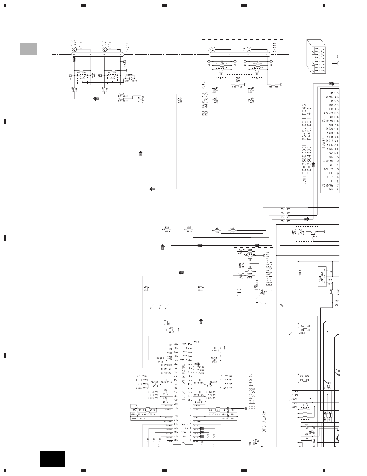
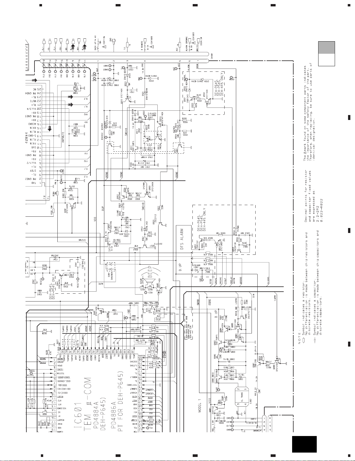
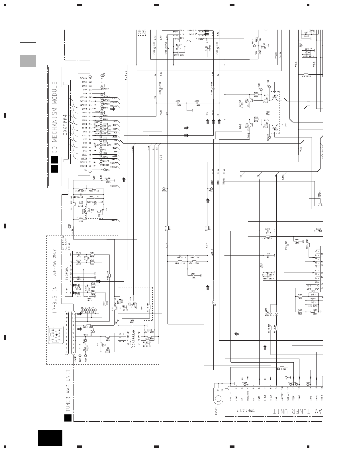
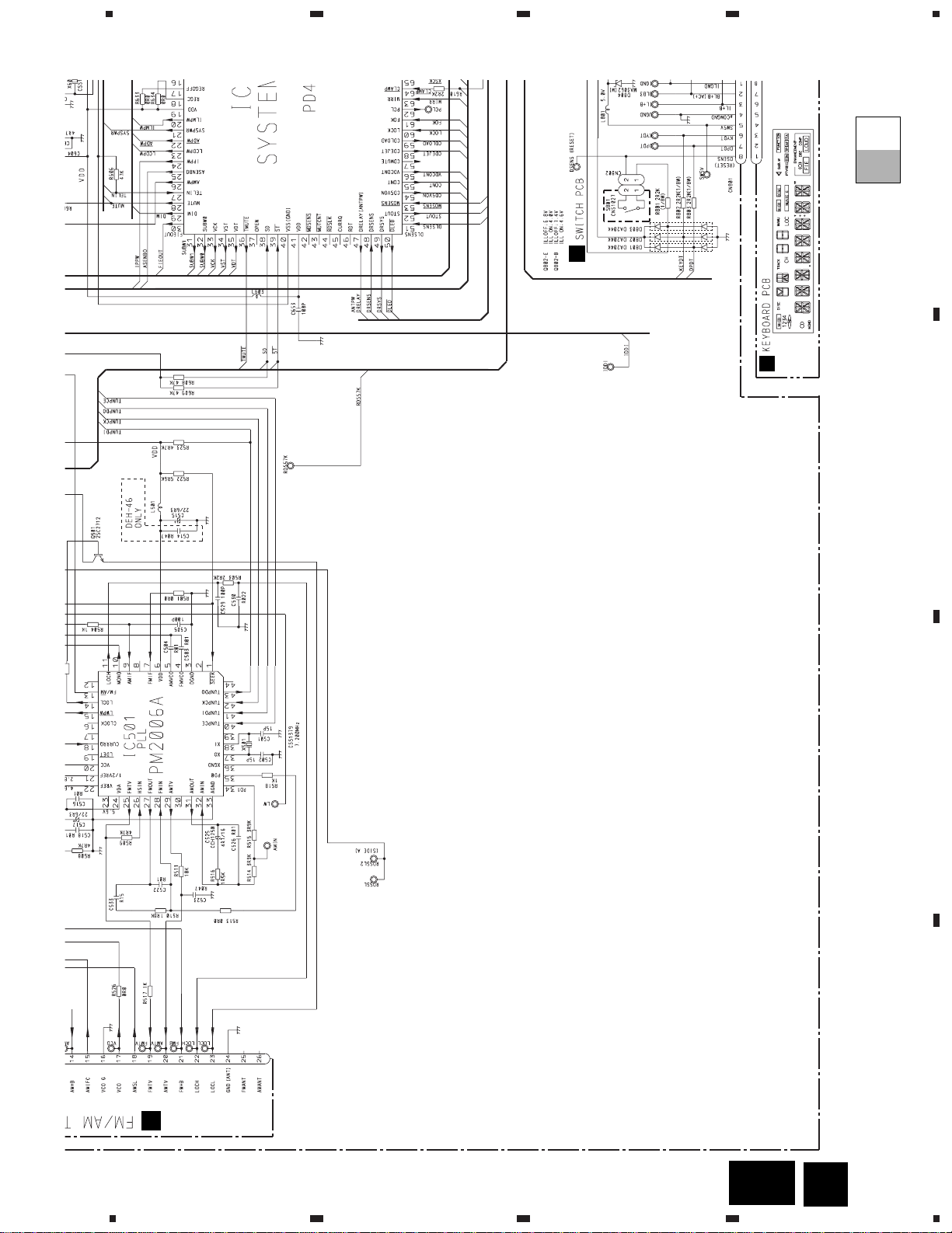
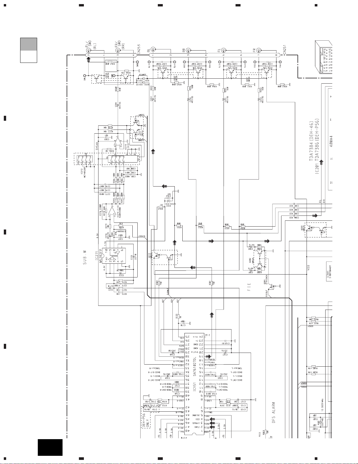
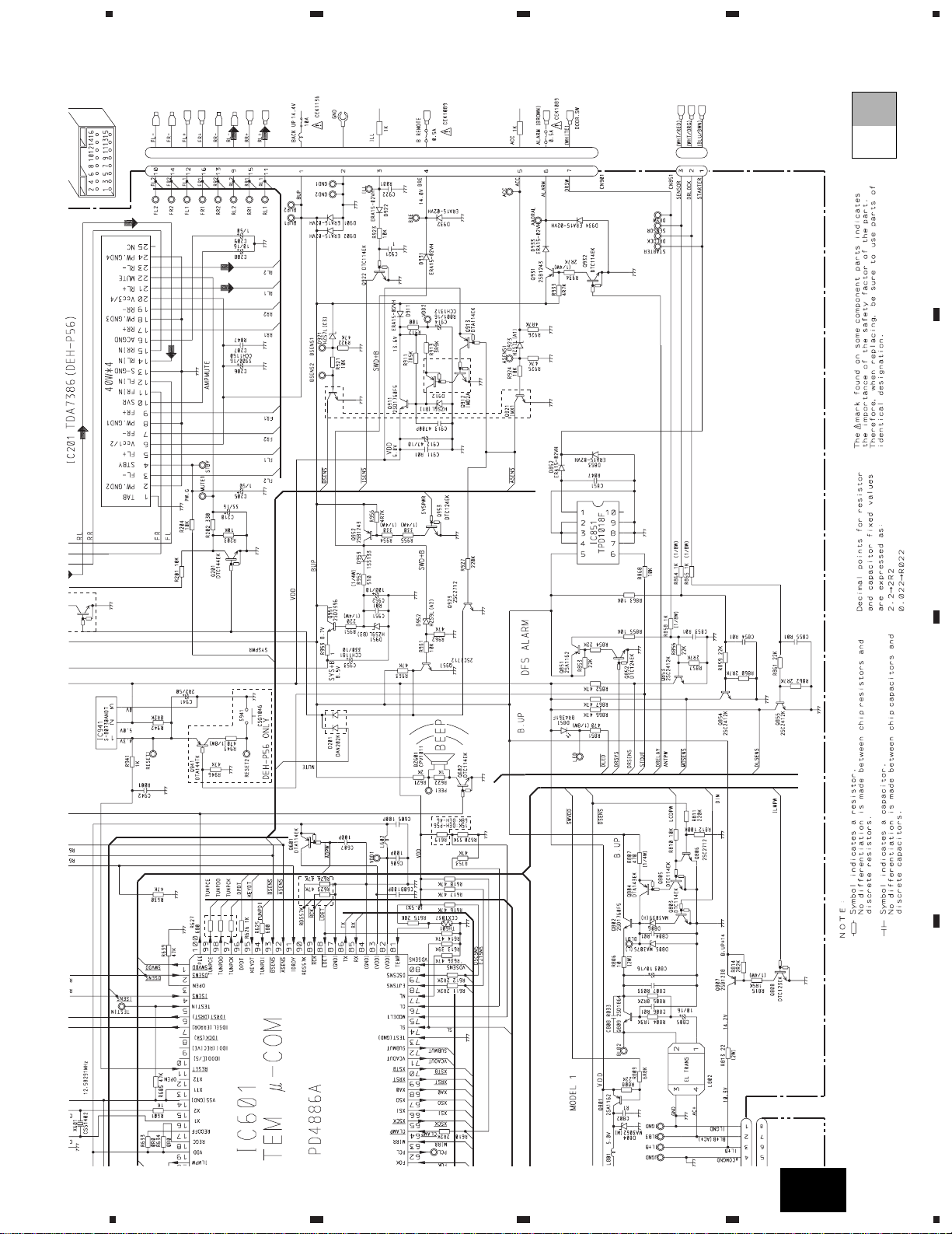
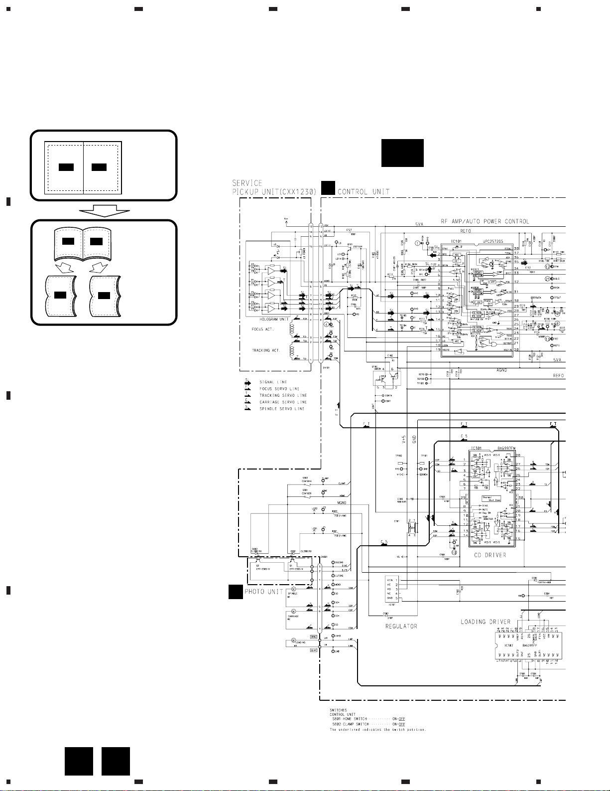
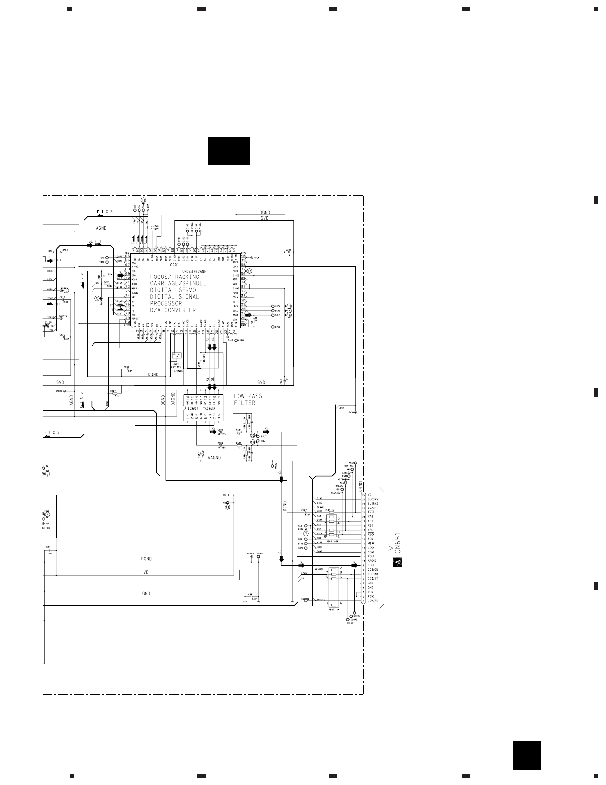
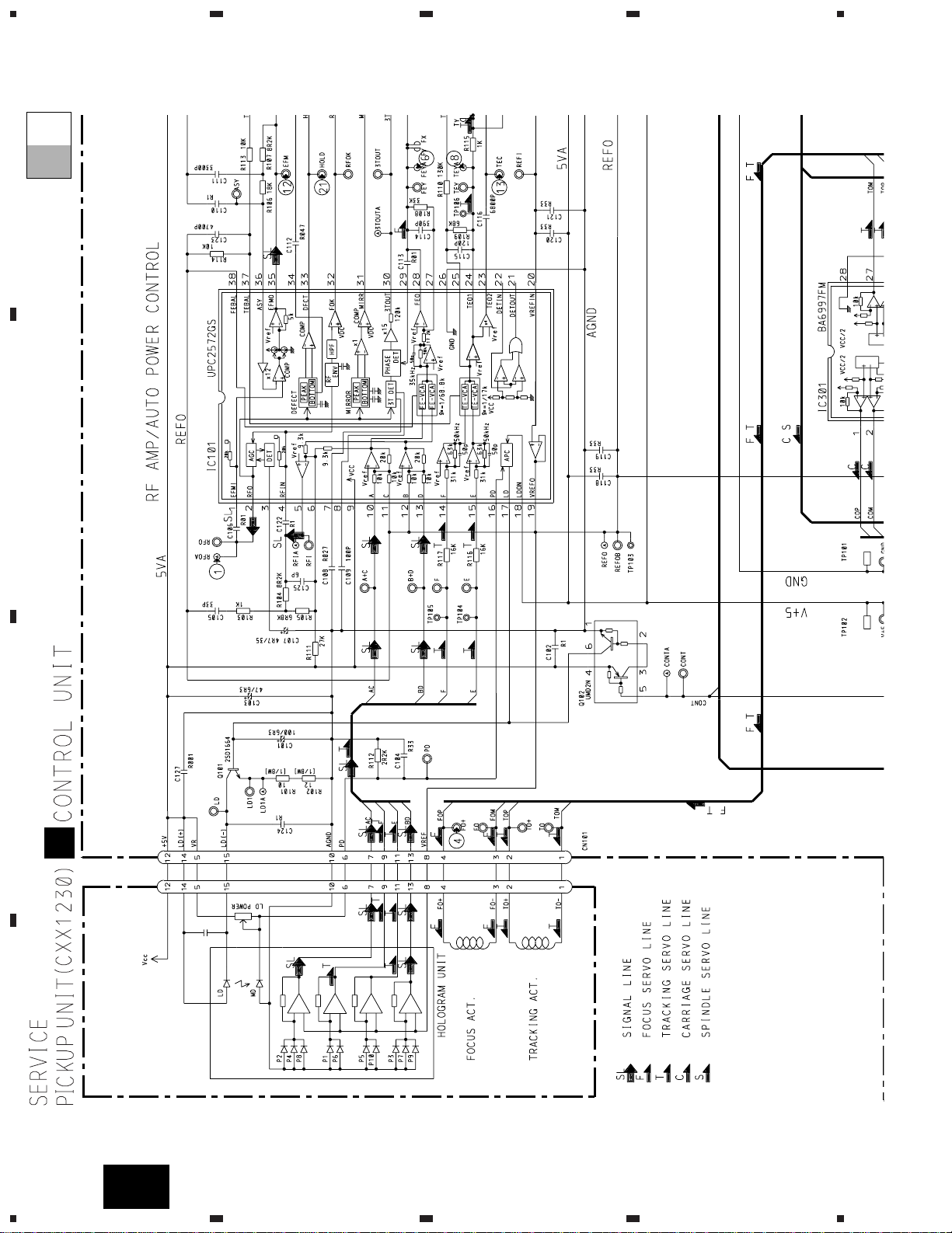
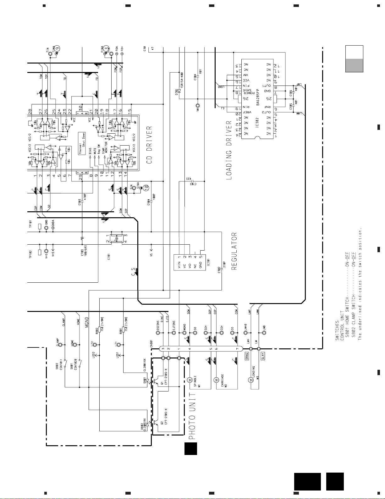
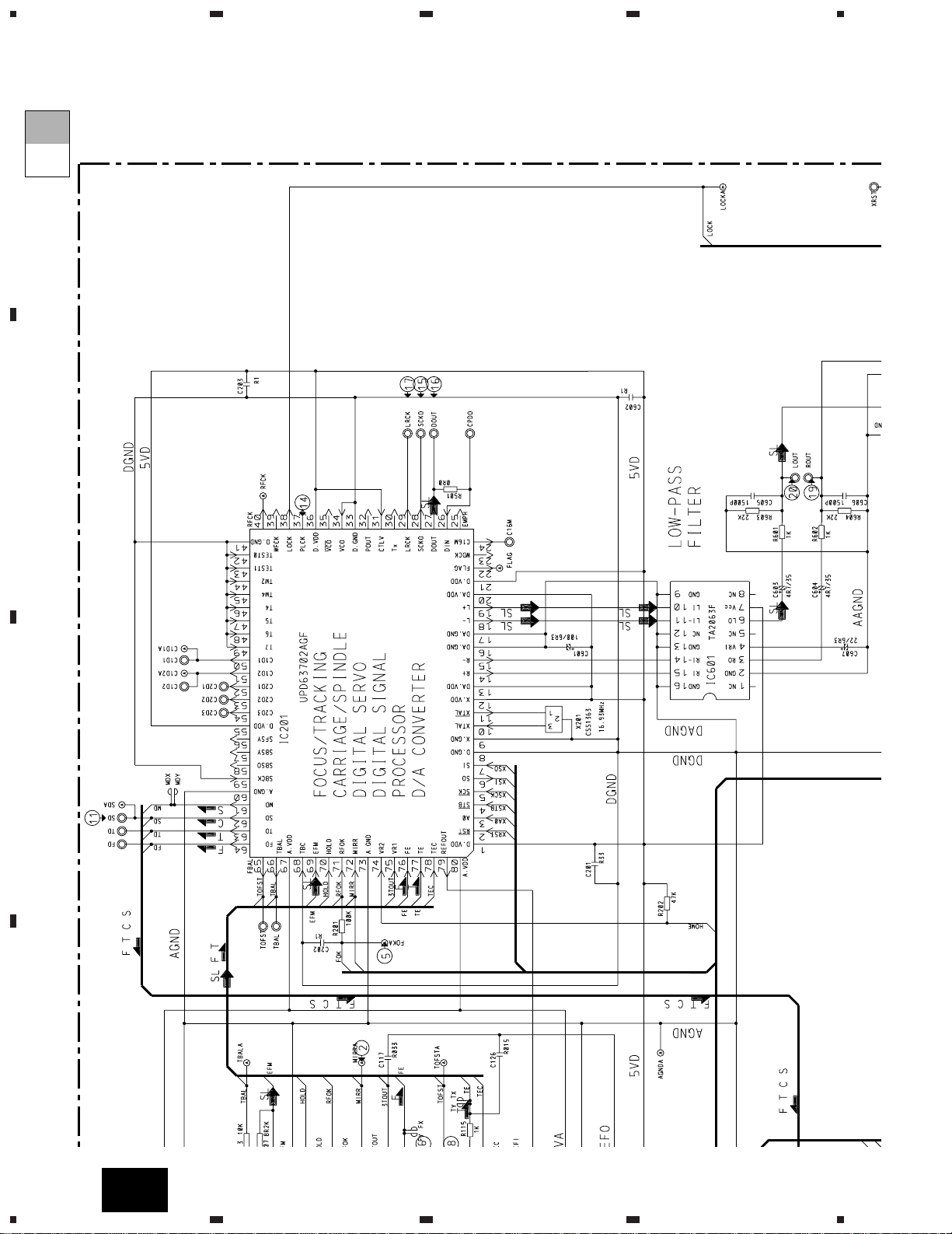
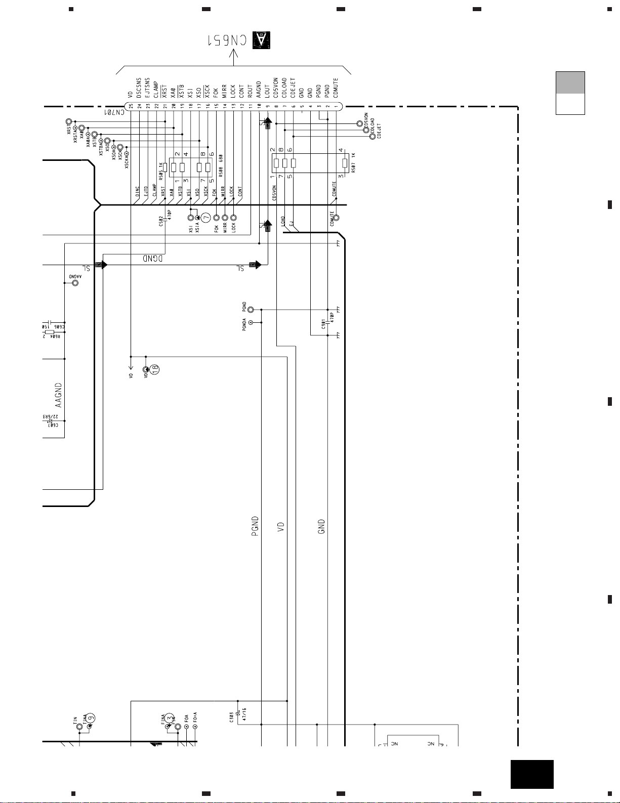
3. SCHEMATIC DIAGRAM
3.1 OVERALL CONNECTION DIAGRAM(GUIDE PAGE)
Note: When ordering service parts, be sure to refer to “EXPLODED VIEWS AND PARTS LIST” or “ELECTRICAL PARTS
LIST”.
- DEH-P645/UC,DEH-P545/UC,DEH-445/UC,DEH-41/UC
F
13
DEH-P645,P56,P545,46,445,41
5
6
78
5
6
78
D
C
B
A
A
A-b
Fig. 4
A
D E
14
DEH-P645,P56,P545,46,445,41
1
23
4
1234
D
C
B
A
A-a
A-b
A-a
F
C
B
15
DEH-P645,P56,P545,46,445,41
5
6
78
5
6
7
D
C
B
A
A-a
A-b
A-a
8
Fig. 5
F
16
DEH-P645,P56,P545,46,445,41
1
23
4
234
D
C
B
A
A-a
A-b
A-b
1
17
DEH-P645,P56,P545,46,445,41
5
6
78
5
6
7
D
C
B
A
A-a
A-b
A-b
8
Fig. 6
18
DEH-P645,P56,P545,46,445,41
1
23
4
1234
D
C
B
A
A
A-a A-b
A-a
A-b
A-b
A-a
Large size
SCH diagram
Guide page
Detailed page
A-a
A
EBD
F
C
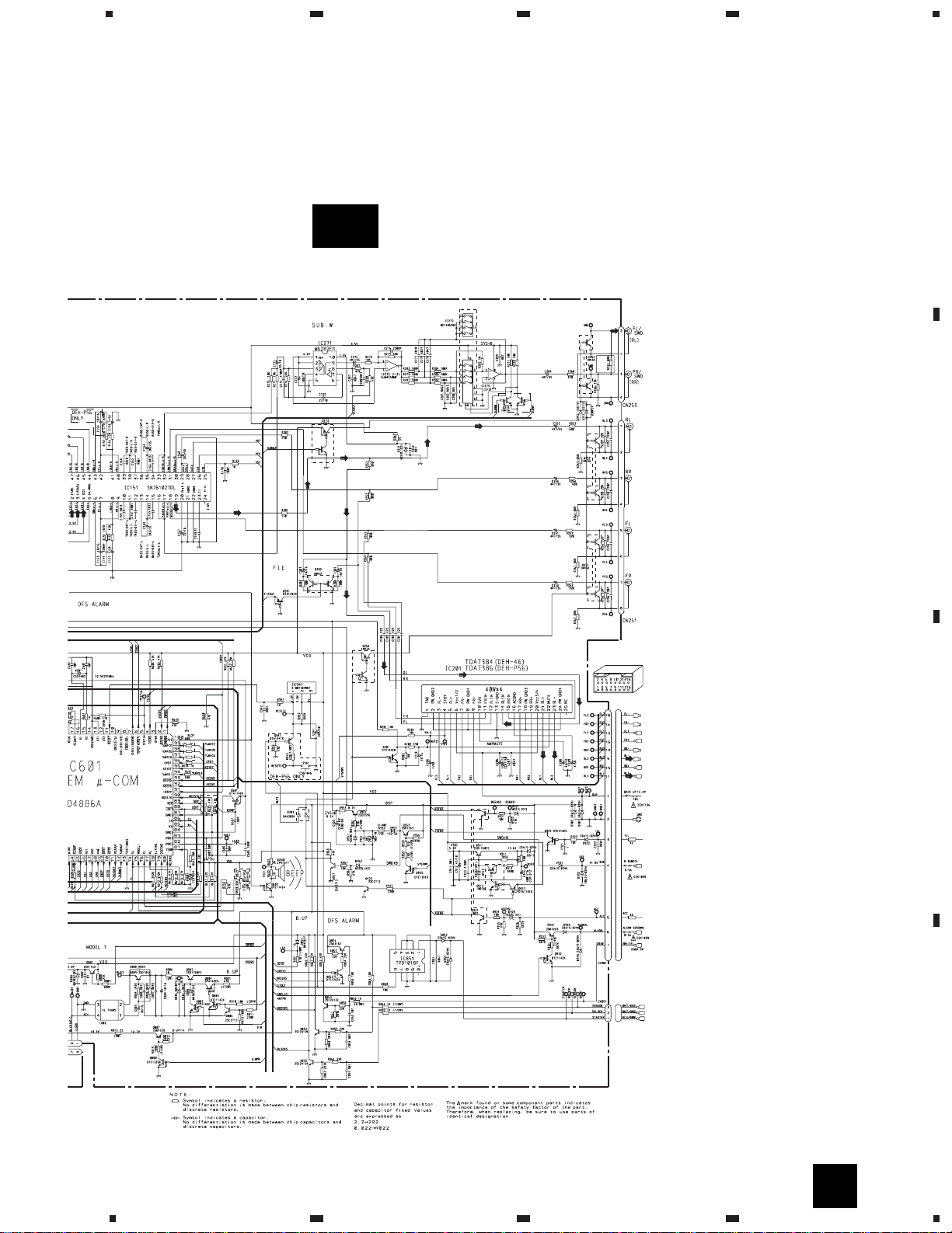
3.2 OVERALL CONNECTION DIAGRAM(GUIDE PAGE)
- DEH-P56/UC,DEH-46/UC
19
DEH-P645,P56,P545,46,445,41
5
6
78
5
6
78
D
C
B
A
A
A-b
Fig. 7
20
DEH-P645,P56,P545,46,445,41
1
23
4
1
234
D
C
B
A
A
ED
A-a
A-b
A-a
21
DEH-P645,P56,P545,46,445,41
5
6
78
5
6
78
D
C
B
A
B
C
F
A-a
A-b
A-a
Fig. 8
F
22
DEH-P645,P56,P545,46,445,41
1
23
4
234
D
C
B
A
A-a
A-b
A-b
1
23
DEH-P645,P56,P545,46,445,41
5
6
78
5
6
7
D
C
B
A
A-a
A-b
A-b
8
Fig. 9
24
DEH-P645,P56,P545,46,445,41
1
23
4
234
D
C
B
A
1
D
E
3.3 CD MECHANISM MODULE(GUIDE PAGE)
A-a A-b
A-a
A-b
A-b
A-a
Large size
SCH diagram
Guide page
Detailed page
D-a
E
D
22/6R3
BA05SFP
CXA8912
CXA8986
CXA8702
25
DEH-P645,P56,P545,46,445,41
5
6
78
5
6
7
D
C
B
A
8
D-b
D
Fig. 10
26
DEH-P645,P56,P545,46,445,41
1
23
4
234
D
C
B
A
1
D
D-a
D-a
D-b
27
DEH-P645,P56,P545,46,445,41
5
6
78
5
6
7
D
C
B
A
8
E
22/6R3
BA05SFP
CXA8912
CXA8986
CXA8702
D-a
E
D-a
D-b
Fig. 11
28
DEH-P645,P56,P545,46,445,41
1
23
4
234
D
C
B
A
D-b
D-a
D-b
1
29
DEH-P645,P56,P545,46,445,41
5
6
78
5
6
7
D
C
B
A
D-b
D-a
D-b
8
Fig. 12
30
DEH-P645,P56,P545,46,445,41
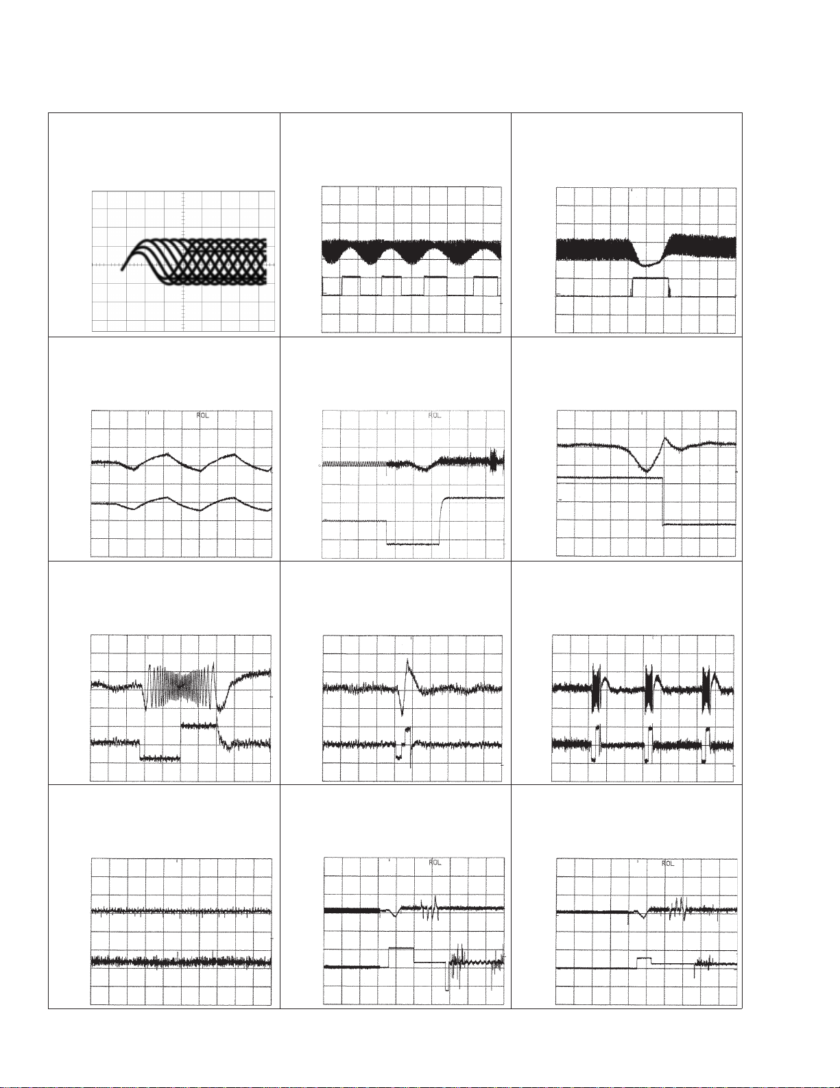
- Waveforms
1 RFO 0.5V/div. 0.5µs/div.
Normal mode: play
1 CH1: RFO 1V/div.
2 CH2: MIRR 5V/div.
Test mode: Tracking open
0.5ms/div.
1 CH1: RFO 1V/div.
2 CH2: MIRR 5V/div.
Normal mode: The defect part
passes 800µm
0.5ms/div.
3 CH1: FIN 0.5V/div.
4 CH2: FO+ 2V/div.
Test mode: No disc, Focus close
0.2s/div.
3 CH1: FIN 0.5V/div.
5 CH2: FOK 2V/div.
Normal mode: Focus close
0.2s/div.
6 CH1: FEY 0.5V/div.
7 CH2: XSI 2V/div.
Normal mode: Focus close
1ms/div.
REFO
→
8 CH1: TEY 0.5V/div.
9 CH2: TIN 0.5V/div.
Test mode: 32 tracks jump (FWD)
0.5ms/div.
8 CH1: TEY 0.5V/div.
9 CH2: TIN 0.5V/div.
Test mode: Single jump (FWD)
0.5ms/div.
8 CH1: TEY 0.5V/div.
9 CH2: TIN 0.5V/div.
Test mode: 100 tracks jump (FWD)
5ms/div.
6 CH1: FEY 0.1V/div.
3 CH2: FIN 0.2V/div.
Normal mode: Play
20ms/div.
3 CH1: FIN 0.5V/div.
0 CH2: SIN 1V/div.
Normal mode: Focus close (12cm)
0.5s/div.
3 CH1: FIN 0.5V/div.
0 CH2: SIN 1V/div.
Normal mode: Focus close (8cm)
0.5s/div.
GND
→
GND
→
REFO
→
REFO
→
REFO
→
REFO
→
GND
→
REFO
→
REFO
→
GND
→
REFO
→
REFO
→
REFO
→
REFO
→
REFO
→
REFO
→
REFO
→
REFO
→
REFO
→
REFO
→
REFO
→
REFO
→
Note:1. The encircled numbers denote measuring pointes in the circuit diagram.
2. Reference voltage
REFO:2.5V
 Loading...