


AVHP6600DVD

English
Español
Deutsch
Français
Italiano
Nederlands
AVH-P6600DVD
This product conforms to new cord colors.
Los colores de los cables de este producto se confor-
man con un nuevo código de colores.
Dieses Produkt entspricht den neuen Kabelfarben.
Le code de couleur des câbles utilisé pour ce produit est
nouveau.
Questo prodotto è conforme ai nuovi codici colori.
De kleuren van de snoeren van dit toestel zijn gewijzigd.
INSTALLATION MANUAL
MANUEL D’INSTALLATION
1
Contents
Connecting the Units ................................ 1
Connecting the power cord .............................. 3
When connecting to separately sold power
amp ............................................................ 5
When connecting with a rear view camera ...... 7
When connecting with a multi-channel
processor .................................................... 8
Connecting and installing the
optical cable connection box ...................... 9
When connecting the external video
component and the display ...................... 10
Installation ................................................ 11
Installing the remote control unit .................... 11
DIN Front/Rear-mount .................................... 12
DIN Front-mount ............................................ 12
DIN Rear-mount .............................................. 13
Fixing the front panel ...................................... 13
WARNING
• To avoid the risk of accident and the potential
violation of applicable laws, the front DVD or TV
(sold separately) feature should never be used
while the vehicle is being driven. Also, Rear
Displays should not be in a location where it is a
visible distraction to the driver.
• In some countries or states the viewing of
images on a display inside a vehicle even by
persons other than the driver may be illegal.
Where such regulations apply, they must be
obeyed and this unit’s DVD features should
not be used.
CAUTION:
• PIONEER does not recommend that
you install or service your display your-
self. Installing or servicing the product
may expose you to risk of electric shock
or other hazards. Refer all installation
and servicing of your display to autho-
rized Pioneer service personnel.
• Secure all wiring with cable clamps or
electrical tape. Do not allow any bare
wiring to remain exposed.
• Do not drill a hole into the engine com-
partment to connect the yellow lead of
the unit to the vehicle battery. Engine
vibration may eventually cause the insu-
lation to fail at the point where the wire
passes from the passenger compartment
into the engine compartment. Take
extra care in securing the wire at this
point.
• It is extremely dangerous to allow the
display lead to become wound around
the steering column or gearshift. Be sure
to install the display in such a way that
it will not obstruct driving.
• Make sure that wires will not interfere
with moving parts of the vehicle, such as
the gearshift, parking brake or seat slid-
ing mechanism.
• Do not shorten any leads. If you do, the
protection circuit may fail to work
properly.
WARNING
LIGHT GREEN LEAD AT POWER CONNEC-
TOR IS DESIGNED TO DETECT PARKED
STATUS AND MUST BE CONNECTED TO
THE POWER SUPPLY SIDE OF THE PARK-
ING BRAKE SWITCH. IMPROPER CONNEC-
TION OR USE OF THIS LEAD MAY VIO-
LATE APPLICABLE LAW AND MAY
RESULT IN SERIOUS INJURY OR DAMAGE.
Connecting the Units
English
Español
Deutsch
Français
Italiano
Nederlands
2
Note:
• This unit is for vehicles with a 12-volt battery and
negative grounding. Before installing it in a recre-
ational vehicle, truck, or bus, check the battery
voltage.
• To avoid shorts in the electrical system, be sure to
disconnect the ≠ battery cable before beginning
installation.
• Refer to the owner’s manual for details on
connecting the power amp and other units, then
make connections correctly.
• Secure the wiring with cable clamps or adhesive
tape. To protect the wiring, wrap adhesive tape
around them where they lie against metal parts.
• Route and secure all wiring so it cannot touch any
moving parts, such as the gear shift, handbrake
and seat rails. Do not route wiring in places that
get hot, such as near the heater outlet. If the insu-
lation of the wiring melts or gets torn, there is a
danger of the wiring short-circuiting to the vehicle
body.
• Don’t pass the yellow lead through a hole into the
engine compartment to connect to the battery.
This will damage the lead insulation and cause a
very dangerous short.
• Do not shorten any leads. If you do, the protection
circuit may fail to work when it should.
• Never feed power to other equipment by cutting
the insulation of the power supply lead of the unit
and tapping into the lead. The current capacity of
the lead will be exceeded, causing overheating.
• When replacing fuse, be sure to use only fuse of
the rating prescribed on the fuse holder.
• Since a unique BPTL circuit is employed, never
wire so the speaker leads are directly grounded or
the left and right ≠ speaker leads are common.
• If the RCA pin jack on the unit will not be used,
do not remove the caps attached to the end of the
connector.
• Speakers connected to this unit must be high-
power types with minimum rating of 50 W and
impedance of 4 to 8 ohms. Connecting speakers
with output and/or impedance values other than
those noted here may result in the speakers catch-
ing fire, emitting smoke, or becoming damaged.
• When this product’s source is switched ON, a
control signal is output through the blue/white
lead. Connect to an external power amp’s system
remote control or the car’s Auto-antenna relay
control terminal (max. 300 mA 12 V DC). If the
car features a glass antenna, connect to the anten-
na booster power supply terminal.
• When an external power amp is being used with
this system, be sure not to connect the blue/white
lead to the amp’s power terminal. Likewise, do
not connect the blue/white lead to the power ter-
minal of the auto-antenna. Such connection could
cause excessive current drain and malfunction.
• To avoid short-circuiting, cover the disconnected
lead with insulating tape. Especially, insulate the
unused speaker leads without fail. There is a pos-
sibility of short-circuiting if the leads are not insu-
lated.
• To prevent incorrect connection, the input side of
the IP-BUS connector is blue, and the output side
is black. Connect the connectors of the same col-
ors correctly.
• This unit cannot be installed in a vehicle that
does not have an ACC (accessory) position on
the ignition switch. (Fig. 1)
Fig. 1
• The black lead is ground. Please ground this lead
separately from the ground of high-current prod-
ucts such as power amps.
If you ground the products together and the
ground becomes detached, there is a risk of dam-
age to the products or fire.
No ACC positionACC position
O
N
S
T
A
R
T
O
F
F
A
C
C
O
N
S
T
A
R
T
O
F
F
• Cords for this product and those for other prod-
ucts may be different colors even if they have
the same function. When connecting this product
to another product, refer to the supplied manuals
of both products and connect cords that have the
same function.

3
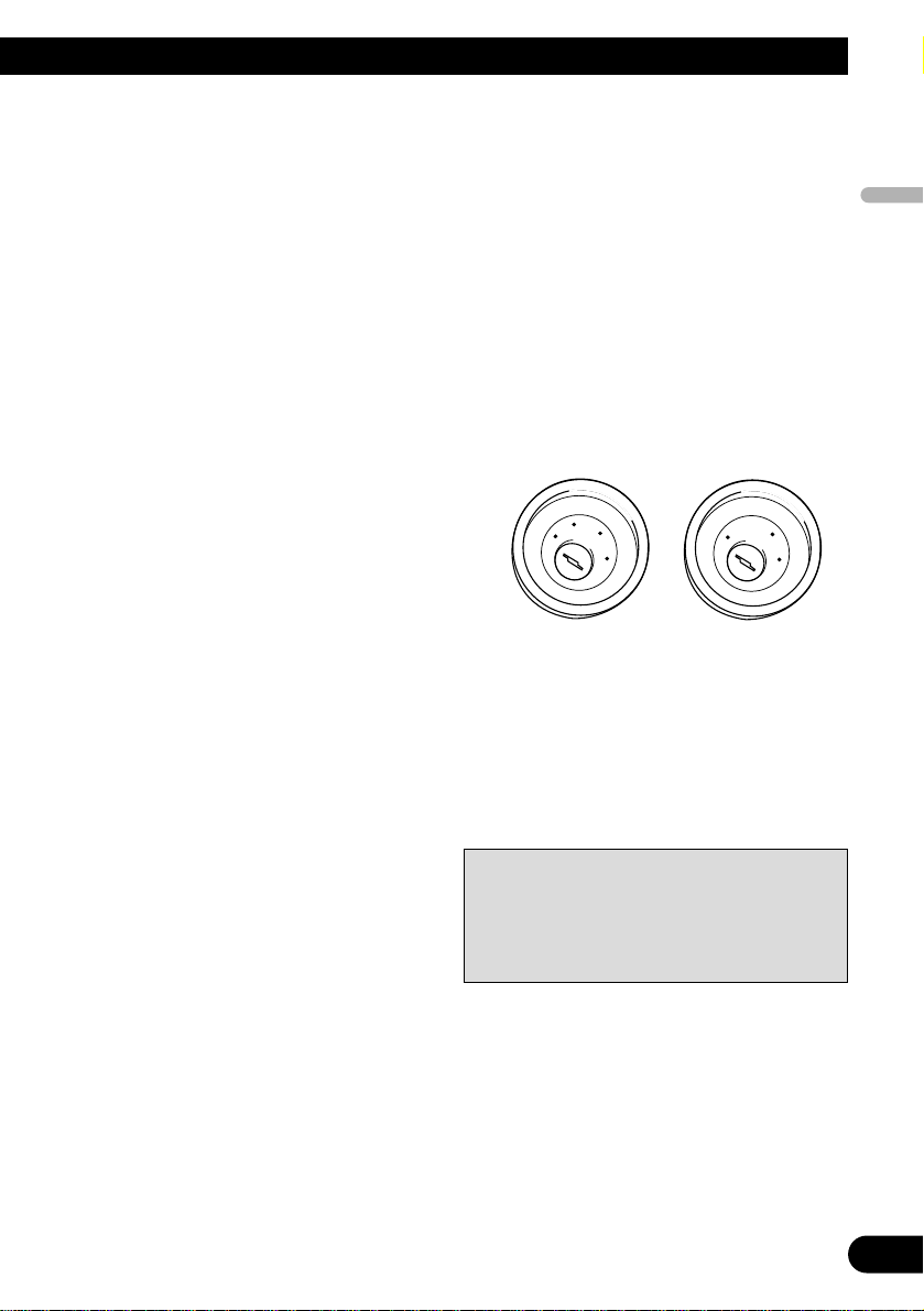
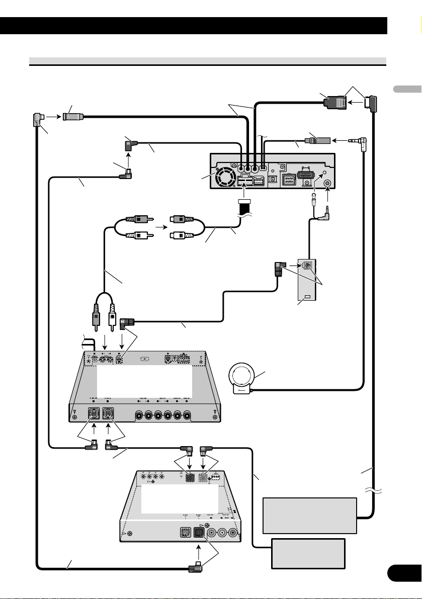
Connecting the Units
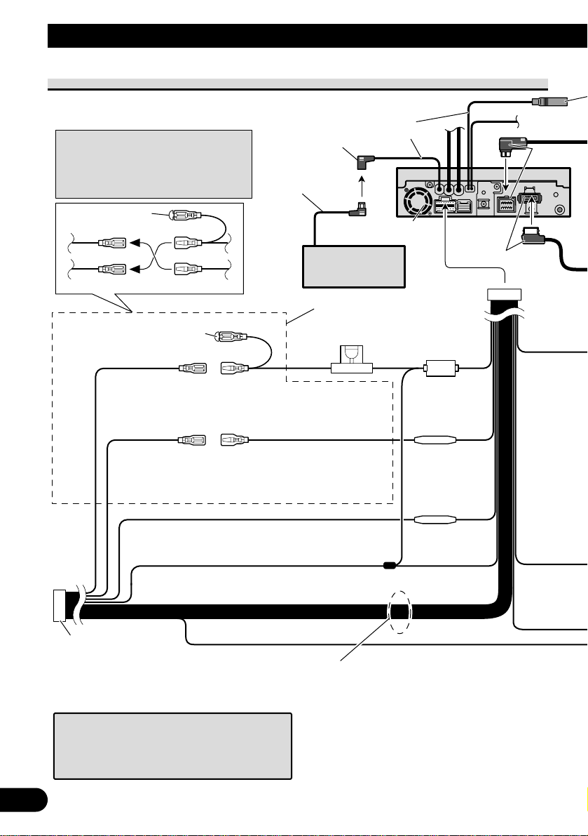
Connecting the power cord
Connect leads of the same
color to each other.
Cap (1*)
When not using this terminal,
do not remove the cap.
ISO connector
Fuse holder
1*
2*
4*
3*
5*
Yellow (2*)
To terminal always supplied
with power regardless of
ignition switch position.
Red (4*)
To electric terminal controlled
by ignition switch (12 V DC)
ON/OFF.
Yellow (3*)
Back-up
(or accessory)
Red (5*)
Accessory
(or back-up)
Black (ground)
To vehicle (metal) body.
Orange/white
To lighting switch terminal.
Note:
In some vehicles, the ISO connector
may be divided into two. In this case,
be sure to connect to both connectors.
Fuse resistor
Fuse resistor
Speaker leads
White: Front left +
White/black: Front left ≠
Gray: Front right +
Gray/black: Front right ≠
Green: Rear left + or Subwoofer +
Green/black: Rear left ≠ or Subwoofer ≠
Violet: Rear right + or Subwoofer +
Violet/black: Rear right ≠ or Subwoofer ≠
Black
Multi-CD player
(sold separately)
IP-BUS cable
Violet
15 cm
This product
IP-BUS input (Blue)
When you connect separately sold multi-channel
processor (DEQ-P6600) to this unit, do not
connect anything to the speaker leads and system
remote control (blue/white).
Note:
Depending on the kind of vehicle, the
function of 3* and 5* may be different.
In this case, be sure to connect 2* to 5*
and 4* to 3*.

English
Español
Deutsch
Français
Italiano
Nederlands
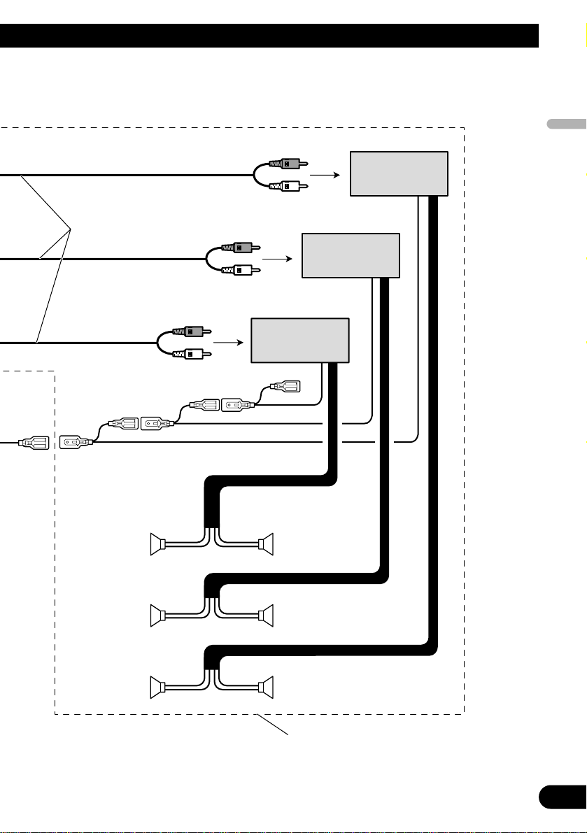
Fig. 2
4
Parking brake
switch
Power supply side
Ground side
Light green
Used to detect the ON/OFF status of the parking brake.
This lead must be connected to the power supply side of the parking
brake switch.
Yellow/black
If you use a cellular telephone, connect it via the
Audio Mute lead on the cellular telephone. If not,
keep the Audio Mute lead free of any connections.
Blue/white (7*)
To Auto-antenna relay control terminal
(max. 300 mA 12 V DC).
Blue/white (6*)
Blue/white
To system control terminal of the power amp
(max. 300 mA 12 V DC).
Antenna jack
Violet
Black
1.5 m
Antenna cable (supplied)
2m
26 pin cable (supplied)
21 pin cable (supplied)
Hide-away unit
The pin position of the ISO connector will differ
depending on the type of vehicle. Connect 6* and
7* when Pin 5 is an antenna control type. In
another type of vehicle, never connect 6* and 7*.
Note:
• The position of the parking brake switch depends
on the vehicle model. For details, consult the
vehicle Owner’s Manual or dealer.
Connection method
Clamp the lead.1. 2. Clamp firmly with
needle-nosed
pliers.
Jack for Wired Remote Control
Please see the Instruction Manual for the
Wired Remote Control (sold separately).

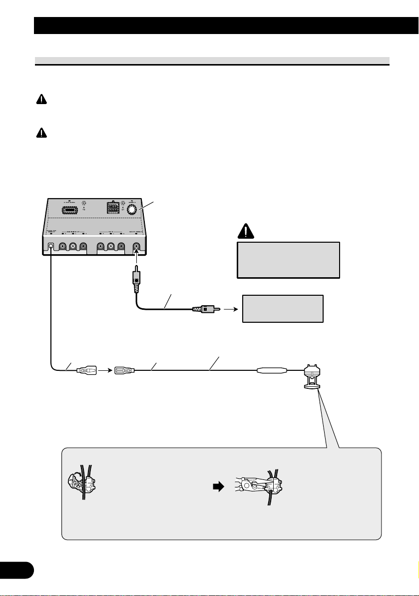
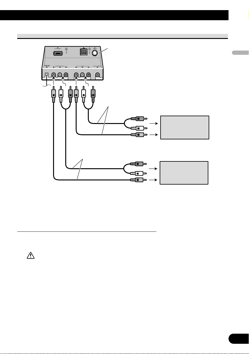
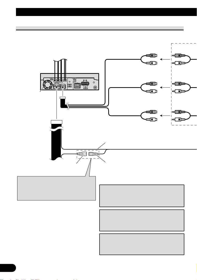
When connecting to separately sold power amp
5
Connecting the Units
When you connect separately sold
multi-channel processor (e.g. DEQ-P6600)
to this unit, do not connect anything to the
speaker leads and system remote control
(blue/white).
Note:
Change the initial setting of this product
(refer to the Operation Manual).
The subwoofer output of this unit is monaural.
Note:
When you connect multi-channel processor to
this unit, separately sold power amp must be
connected to multi-channel processor.
This product
Front output
(FRONT OUTPUT)
Subwoofer output
or non fading output
(SUBWOOFER OUTPUT or
NON-FADING OUTPUT)
Rear output
(REAR OUTPUT)
15 cm
23 cm
15 cm
Blue/white
To system control terminal of the power amp
(max. 300 mA 12 V DC).
Blue/white (7*)
To Auto-antenna relay control terminal
(max. 300 mA 12 V DC).
Blue/white (6*)
The pin position of the ISO connector will differ
depending on the type of vehicle. Connect 6* and
7* when Pin 5 is an antenna control type. In
another type of vehicle, never connect 6* and 7*.
English
Español
Deutsch
Français
Italiano
Nederlands
Fig. 3
6
Power amp
(sold separately)
Power amp
(sold separately)
Power amp
(sold separately)
+
≠
+
≠
+
≠
+
≠
+
≠
+
≠
System remote control
RCA cables
(sold separately)
Front speaker
Rear speaker
Subwoofer
Front speaker
Rear speaker
Subwoofer
Left Right
Perform these connections when using
the optional amplifier.
When connecting with a rear view camera
When using this product with a rear view camera, automatic switching to video from a
rear view camera when the gear shift is moved to REVERSE (R) position is possible.
WARNING
USE INPUT ONLY FOR REVERSE OR MIRROR IMAGE REAR VIEW CAMERA. OTHER USE MAY
RESULT IN INJURY OR DAMAGE.
CAUTION
•
The screen image may appear reversed.
• The rear view camera function is to use this product as an aid to keep an eye on trailers, or backing into a
tight parking spot. Do not use this function for entertainment purposes.
• The object in rear view may appear closer or more distant than in reality.
Fig. 4
7
Connecting the Units
Violet/white
Of the two lead wires connected to the back
lamp, connect the one in which the voltage
changes when the gear shift is in the REVERSE
(R) position. This connection enables the unit to
sense whether the car is moving forwards or
backwards.
You must use a camera
which outputs mirror
reversed images.
CAUTION
Note:
• It is necessary to set to BACK UP CAMERA in SETUP
when connecting the rear view camera.
Connection method
Clamp the lead.1. 2. Clamp firmly with
needle-nosed
pliers.
Hide-away unit
Fuse resistor
8m
Extension lead (supplied)
Rear view camera
RCA cable
(sold separately)
10 cm
To video output
English
Español
Deutsch
Français
Italiano
Nederlands
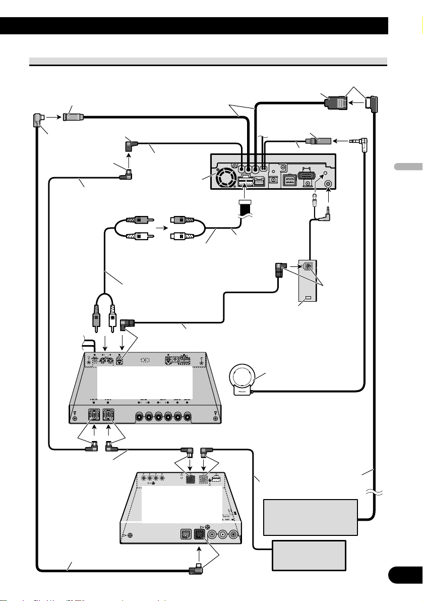
When connecting with a multi-channel processor
Fig. 5
8
Multi-channel processor
(DEQ-P6600)
(sold separately)
IP-BUS cable
15 cm
This product
IP-BUS input (Blue)
Hide-away TV tuner
(e.g. GEX-P6400TVP)
(sold separately)
AV-BUS input (Blue)
26 pin cable
Yellow
AV-BUS cable (supplied
with TV tuner)
IP-BUS cable
(supplied with TV tuner)
Subwoofer output
or non fading output
(SUBWOOFER OUTPUT or
NON-FADING OUTPUT)
23 cm
RCA cable (supplied with
multi-channel processor)
40 cm
Black
Blue
BlueBlack
Black Blue
Black
Blue
Blue
IP-BUS cable (supplied with
multi-channel processor)
Optical cable (supplied with
multi-channel processor)
Optical cable connection box
(supplied with multi-channel processor)
15 cm
Guide speaker output
(GUIDE SP OUTPUT)
Guide speaker
(e.g. CD-TS37GP)
(sold separatly)
If you use this unit with navigation unit
(e.g. AVIC-900DVD) and multi-channel
processor (e.g. DEQ-P6600), be sure to
connect a guide speaker to this unit’s
guide speaker output terminal.
26 pin cable input
Navigation unit
(e.g. AVIC-900DVD)
(sold separately)
Multi-CD player
(sold separately)

9
Connecting the Units
Connecting and installing the
optical cable connection box
WARNING
• Avoid installing this unit in such a location where
the operation of safety devices such as airbags is
prevented by this unit. Otherwise, there is a dan-
ger of a fatal accident.
• Avoid installing this unit in such a location where
the operation of the brake may be prevented.
Otherwise, it may result in a traffic accident.
• Fix this unit securely with the velcro tape or lock
tie. If this unit is loose, it disturbs driving stabili-
ty, which may result in a traffic accident.
CAUTION
• Install this unit using only the parts supplied with
this unit. If other parts are used, this unit may be
damaged or could dismount itself, which leads to
an accident or trouble.
• Do not install this unit near the doors where rain-
water is likely to be spilled on the unit. Incursion
of water into the unit may cause smoke or fire.
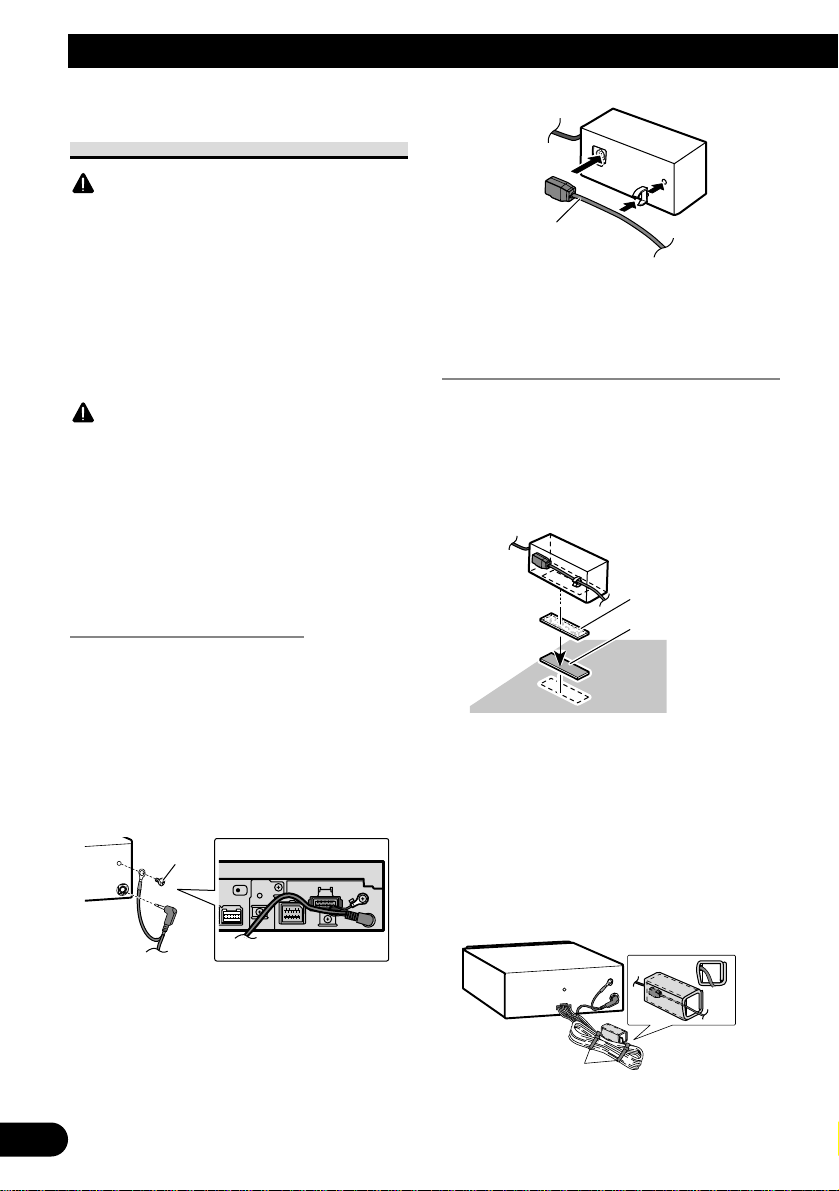
Connecting the optical cable
1. Connect the optical cable and
ground lead to the main unit.
(Fig. 6)
Connect the optical cable so that it
does not protrude from the unit, as
shown in the illustration. Fasten the
ground lead to the protrusion on the
back of the unit.
Fig. 6
2.
Connect the optical cable to the
optical cable connection box.
(Fig. 7)
Fig. 7
Installing the optical cable
connection box
• When
installing the optical cable
connection box with the velcro
tape. (Fig. 8)
Install the optical cable connection
box using the velcro tape in the ample
space of the console box.
Fig. 8
• When installing the optical cable
connection box with the lock tie.
(Fig. 9)
Wrap the optical cable and connection
box with the protection tape and fasten
with the power code using the lock tie.
Fig. 9
Fasten with the lock tie
Wrap with the protection tape
Velcro tape (hard)
Velcro tape (soft)
Optical cable
Screw
English
Español
Deutsch
Français
Italiano
Nederlands
10
When connecting the external video component and the display
Fig. 10
• It is necessary to set to AV INPUT in SET UP when connecting the external video
component.
When using a display connected to rear video output
This product’s rear video output is for connection of a display to enable passengers in the
rear seats to watch the DVD or Video CD.
WARNING:
• NEVER install the display in a location that enables the Driver to watch the DVD or Video CD
while Driving.
• NEVER connect rear audio output (REAR MONITOR OUT) to sold separately power amp.
Hide-away unit
External video
component
(sold separately)
RCA cables
(sold separately)
Display with
RCA input jacks
RCA cables
(sold separately)
To video input
To audio inputs
To video output
To audio outputs
11
Installation
Note:
• Before finally installing the unit, connect the
wiring temporarily, making sure it is all connect-
ed up properly, and the unit and the system work
properly.
• Use only the parts included with the unit to ensure
proper installation. The use of unauthorized parts
can cause malfunctions.
• Consult with your nearest dealer if installation
requires the drilling of holes or other modifica-
tions of the vehicle.
• Install the unit where it does not get in the dri-
ver’s way and cannot injure the passenger if there
is a sudden stop, like an emergency stop.
• Do not install the display where it may (i) obstruct
the driver's vision, (ii) impair the performance of
any of the vehicle's operating systems or safety
features, including air bags, hazard lamp buttons
or (iii) impair the driver's ability to safely operate
the vehicle.
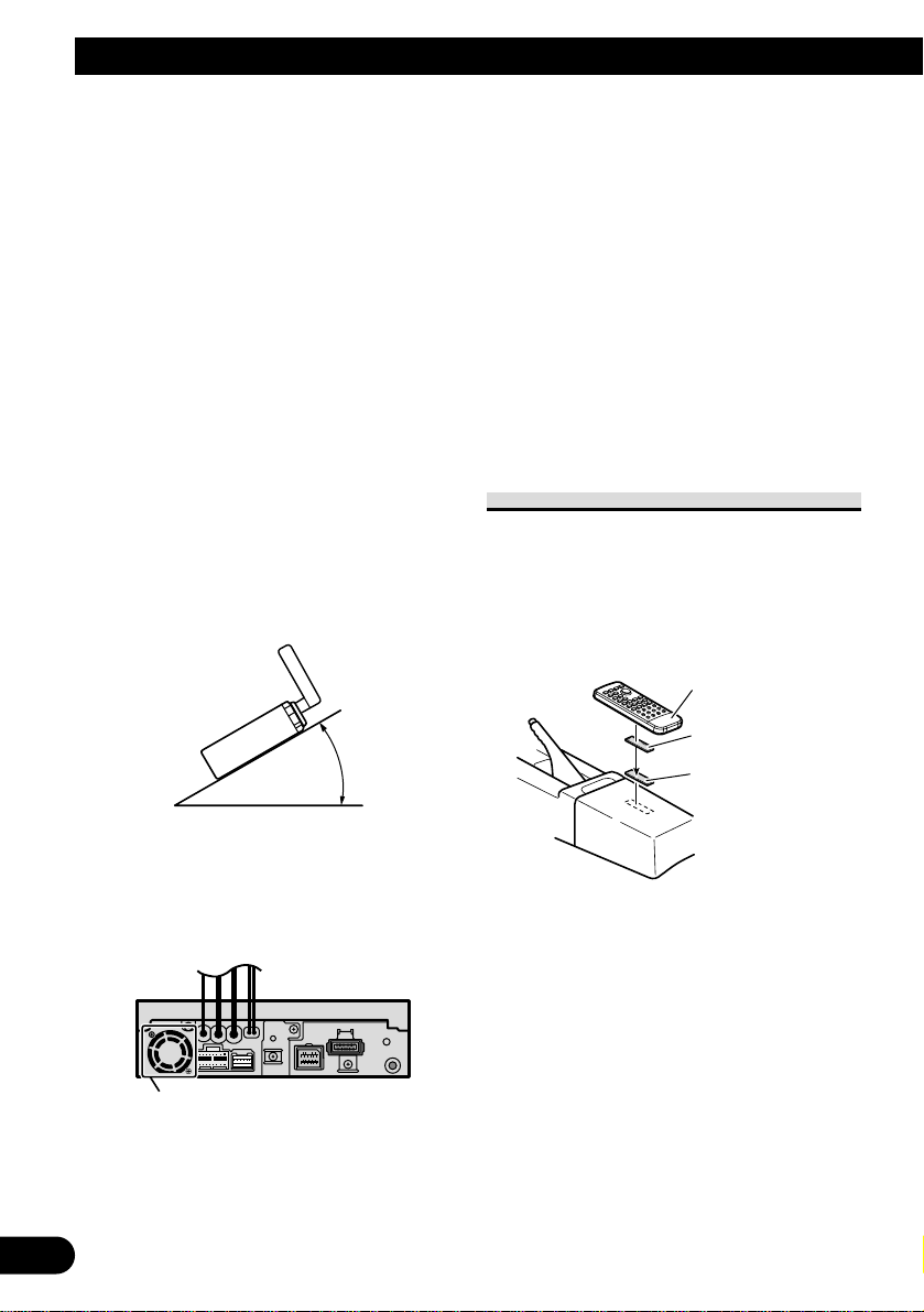
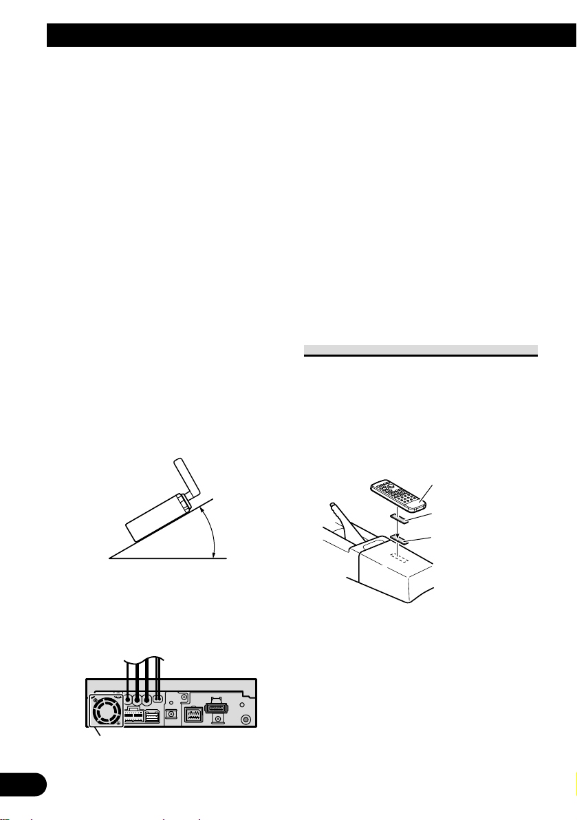
• The semiconductor laser will be damaged if it
overheats, so don’t install the unit anywhere hot
— for instance, near a heater outlet.
• If installation angle exceeds 30° from horizontal,
the unit might not give its optimum performance.
(Fig. 11)
Fig. 11
• The cords must not cover up the area shown in the
figure below. This is necessary to allow the
amplifires to radiate freely. (Fig. 12)
Fig. 12
• When mounting the hide-away unit, make sure
none of the leads are trapped between the hide-
away unit and the surrounding metalwork or fit-
tings.
• Do not mount the hide-away unit near the heater
outlet, where it would be affected by heat, or near
the doors, where rainwater might splash onto it.
• If the hide-away unit is installed in the passenger
compartment, anchor it securely so it does not
break free while the car is moving, and cause
injury or an accident.
• If the hide-away unit is installed under a front
seat, make sure it does not obstruct seat move-
ment. Route all leads and cords carefully around
the sliding mechanism so they do not get caught
or pinched in the mechanism and cause a short
circuit.
Installing the remote control unit
When not using the remote control
unit, secure it with velcro tape to pre-
vent it from moving.
• Thoroughly wipe off the surface
before affixing the velcro tape.
Fig.13
Velcro tape (small)
(hard)
Velcro tape (small)
(soft)
Remote control unit
Do not close this area.
30°

English
Español
Deutsch
Français
Italiano
Nederlands
12
DIN Front/Rear-mount
This unit can be properly installed
either from “Front” (conventional DIN
Front-mount) or “Rear” (DIN Rear-
mount installation, utilizing threaded
screw holes at the sides of unit chas-
sis). For details, refer to the following
illustrated installation methods.
Before installing the unit
• Remove the frame and the hold-
er. (Fig. 14)
Pull out to remove the frame and then
loosen the screws (2 × 3 mm) to
remove the holder. (When reattaching
the frame, point the side with a groove
downwards and attach it.)
Fig. 14
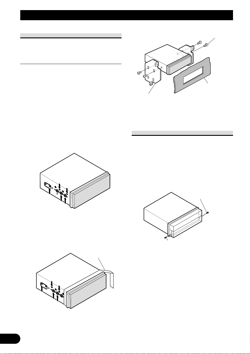
DIN Front-mount
Installation with the rubber bush
1. Decide the position of the side
brackets. (Fig. 15)
When installing in a shallow space,
change the position of side brackets. In
this case, stick conceal tape on parts
that protrude from the dashboard.
Fig. 15
2. Install the unit into the dash-
board. (Fig. 16)
After inserting the holder into the
dashboard, then select the appropriate
tabs according to the thickness of the
dashboard material and bend them.
(Install as firmly as possible using the
top and bottom tabs. To secure, bend
the tabs 90 degrees.)
• After installing the unit into the
dashboard, reattach the frame.
Fig. 16
Rubber bush
Screw
Dashboard
Side bracket
Screw (2 × 3 mm)
182
53
Holder
Conceal tape
Side bracket
Flush surface screw (5 × 6 mm)
Holder
Frame
Screw (2 × 3 mm)
13
Installation
DIN Rear-mount
Installation using the screw holes on
the side of the unit
• Fastening the unit to the factory
radio mounting bracket. (Fig.
17) (Fig. 18) (Fig. 19)
Select a position where the screw holes
of the bracket and the screw holes of
this product become aligned (are fit-
ted), and tighten the screws at 2 places
on each side. Use any of binding
screws (4 × 3 mm), binding screws (5
× 6 mm) or flush surface screws (5 × 6
mm), depending on the shape of the
screw holes in the bracket.
*1 Use binding screws (4 × 3 mm) only.
Fig. 17
• When installing in a shallow space,
use the following screw holes. In
this case, stick conceal tape on parts
that protrude from the dashboard.
Fig. 18
Fig. 19
Fixing the front panel
If you do not operate the removing and
attaching the front panel function, use
the supplied fixing screws to fix the
front panel to this unit.
• Fix the front panel to the unit
using fixing screws after remov-
ing the front panel. (Fig. 20)
Fig. 20
Fixing screw
Fixing screw
Screw
Dashboard or
Console
Factory radio mounting
bracket
*
1
*
1
Conceal tape
*
1
*
1

14
English
Español
Deutsch
Français
Italiano
Nederlands
1
Contenido
Conexión de las unidades ........................ 1
Conexión del cable de alimentación .................. 3
Cuando conecte a un amplificador de
potencia vendido separadamente ................ 5
Cuando conecte con una cámara de
vista trasera ................................................ 7
Cuando conecte con un procesador
multicanal .................................................. 8
Conexión e instalación de la caja de
conexión de cable óptico ............................ 9
Cuando conecte el componente externo
y la pantalla .............................................. 10
Instalación ................................................ 11
Instalación del control remoto ........................ 11
Montaje trasero/delantero DIN ........................ 12
Montaje delantero DIN .................................... 12
Montaje trasero DIN ........................................ 13
Fijación del panel delantero ............................ 13
ADVERTENCIA
• Para evitar el riesgo de accidentes e violación
potencial de las leyes aplicables, no se debe usar
nunca la función de DVD o TV frontal (vendido
separadamente) mientras el vehículo esté siendo
conducido. Igualmente, los monitores traseros no
deben quedarse en un sitio donde puedan causar
una distracción visible al conductor.
• En algunos países o estados, puede ser ilícita la
visualización de imágenes en un display dentro de
un vehículo, incluso por otras personas que no
sean el conductor. En los casos en que resulten
aplicables, estas normas deben respetarse y no
deben usarse las funciones de DVD de esta
unidad.
PRECAUCIÓN:
• PIONEER no recomienda que sea usted
mismo quien instale o revise su pantalla.
La instalación o revisión del producto
puede exponerle a descargas eléctricas u
otros peligros. Solicite que todos los
trabajos de instalación y revisión de su
pantalla los realice el personal de
servicio Pioneer autorizado.
• Asegure todo el cableado con
abrazaderas de cables o cinta para usos
eléctricos. No permita que el cableado
pelado permanezca expuesto.
• No taladre un agujero en el
compartimiento del motor para
conectar el cable amarillo de la unidad a
la batería del vehículo. La vibración del
motor podría estropear el aislamiento
en el punto por donde el cable pasa del
compartimiento de los pasajeros al
compartimiento del motor. Tenga
mucho cuidado para mantener el buen
estado del cable en lo relativo a este
punto.
• Es peligrosísimo dejar que el cable de la
pantalla se enrolle en la base del volante
o en la palanca de cambios. Asegúrese
de instalar la pantalla de forma que ésta
no sea un obstáculo para la conducción.
• Asegúrese de que los cables no
interfieran con partes móviles del
vehículo tales como la palanca de
cambio, el freno de mano o el
mecanismo de deslizamiento de los
asientos.
• No acorte ningún cable. Si lo hace, el
circuito de protección tal vez no
funcione correctamente.
ADVERTENCIA
EL CABLE VERDE CLARO DEL CONECTOR
DE ALIMENTACIÓN ESTÁ DISEÑADO PARA
DETECTAR SI EL VEHÍCULO ESTÁ
ESTACIONADO Y DEBE CONECTARSE CON
EL LADO DE LA FUENTE DE ALIMENTACIÓN
DEL INTERRUPTOR DEL FRENO DE MANO.
LA CONEXIÓN O EL USO INCORRECTO DE
ESTE CABLE PUEDE INFRINGIR LAS LEYES
PERTINENTES Y OCASIONAR LESIONES
FÍSICAS O DAÑOS GRAVES.
Conexión de las unidades

English
Español
Deutsch
Français
Italiano
Nederlands
2
Nota:
• Esta unidad es para vehículos con batería de 12
voltios y con conexión a tierra. Antes de instalar
la unidad en un vehículo recreativo, camioneta, o
autobús, revise el voltaje de la batería.
• Para evitar cortocircuitos en el sistema eléctrico,
asegúrese de desconectar el cable de la batería ≠
antes de comenzar con la instalación.
• Consulte con el manual del usuario para los
detalles sobre la conexión de la alimentación de
amperios y de otras unidades, luego haga las
conexiones correctamente.
• Asegure el cableado con abrazaderas de cables o
con cinta adhesiva. Para proteger el cableado,
envuélvalo con cinta adhesiva donde éstos se
apoyan sobre las piezas de metal.
• Coloque y asegure todo el cableado de tal manera
que no toque las piezas en movimiento, tal como
la palanca de cambio de velocidades, el freno de
mano, y los pasamanos de los asientos. No
coloque el cableado en lugares que se calientan,
tal como cerca de la salida de un calefactor. Si el
material aislante del cableado se derritiera o se
gastara, habrá el peligro de un cortocircuito del
cableado a la carrocería del vehículo.
• No pase el conductor amarillo a través de un orifi-
cio en el compartimiento del motor para conectar
a la batería. Esto dañará el material aislante del
conductor y causará un cortocircuito peligroso.
• No acorte ningún conductor. Si lo hiciera, la pro-
tección del circuito podría fallar al funcionar
cuando debería.
• Nunca alimente energía a otros equipos cortando
el aislamiento del conductor de alimentación pro-
vista de la unidad y haciendo un empalme con el
conductor. La capacidad de corriente del conduc-
tor se excederá, causando el recalentamiento.
• Cuando reemplace algún fusible, asegúrese de uti-
lizar solamente un fusible del ratio descrito en el
soporte de fusibles.
• Ya que se emplea un circuito único BPTL, nunca
coloque los cables de manera que los conductores
del altavoz estén directamente en conexión a tier-
ra o que el altavoz izquierdo y derecho ≠ sean
comunes.
• Si la toma de clavija RCA en la unidad no se usa,
retire las tapas fijadas al extremo del conector.
• Los altavoces conectados a esta unidad deberán
ser del tipo de alta potencia, teniendo un régimen
mínimo de 50 W y una impedancia de 4 a 8
ohmios. La conexión de altavoces con valores de
impedancia y/o de salida diferentes a los anotados
aquí podrían causar fuego, emisión de humo o
daños a los altavoces.
• Cuando se conecta la fuente de este producto, una
señal de control se emite a través del conductor
azul/blanco. Conecte al control remoto de sistema
de un amplificador de potencia externo o al termi-
nal de controle de relé de antena automática del
vehículo (máx. 300 mA 12 V CC). Si el vehículo
tiene una antena en vidrio, conecte al terminal de
suministro de energía de la antena.
• Cuando se está utilizando un amperio de potencia
externa con este sistema, asegúrese de no conectar
el conductor azul/blanco al terminal de potencia
de amperios. Asimismo, no conecte el conductor
azul/blanco al terminal de potencia de la auto-
antena. Tal conexión podría causar la fuga de cor-
riente excesiva y causar fallos de funcionamiento.
• Para evitar cortocircuitos, cubra el conductor
desconectado con cinta aislada. Especialmente,
aísle los conductores de altavoz no usados. Hay la
posibilidad de cortocircuito si no se aíslan los
conductores.
• Para evitar la conexión incorrecta, el lado de en-
trada del conector IP-BUS es azul, y el lado de
salida es negro. Conecte los conectores del mismo
color correctamente.
• Esta unidad no se puede instalar en un
vehículo que no dispone de la posición ACC
(accesorio) en el interruptor de encendido.
(Fig. 1)
Fig. 1
• El conductor negro es la masa. Conecte a masa
este conductor separadamente desde la masa de
los productos de alta corriente tal como los ampli-
ficadores de potencia.
Si conecta juntos a masa los productos y la masa
se desconecta, se crea el riesgo de daños a los pro-
ductos o de incendios.
No en la posición ACCPosición ACC
O
N
S
T
A
R
T
O
F
F
A
C
C
O
N
S
T
A
R
T
O
F
F
• Los cables para este producto y aquéllas para
otros productos pueden ser de colores diferentes
aun si tienen la misma función. Cuando se conec-
ta este producto a otro, refiérase a los manuales
de ambos productos y conecte los cables que
tienen la misma función.
3
Conexión de las unidades
Conexión del cable de alimentación
1*
2*
4*
3*
5*
15 cm
Conecte los conductores del
mismo color uno a otro.
Tapa (1*)
Cuando este terminal no se usa,
no retire la tapa.
Conector ISO
Portafusible
Amarillo (2*)
Al terminal con suministro constante
de electricidad, independientemente
de la posición del interruptor de
encendido.
Rojo (4*)
Al terminal de energía eléctrica
controlado por el interruptor de
encendido del vehículo (12 V de CC.)
ON/OFF.
Amarillo (3*)
Reserva
(o accesorio)
Rojo (5*)
Accesorio
(o reserva)
Negro (masa)
A la carrocería del veículo (parte
metálica).
Anaranjado/blanco
Al terminal de interruptor de
iluminación.
Nota:
En algunos vehículos, el conector ISO puede
estar dividido en dos partes. En este caso,
asegúrese de conectar a ambos conectores.
Resistencia
de fusible
Resistencia
de fusible
Nota:
Dependiendo del tipo del vehículo, la
función de 3* y 5* puede ser diferente.
En este caso, asegúrese de conectar 2* a
5* y 4* a 3*.
Cables de altavoz
Blanco :Izquierdo delantero +
Blanco/negro :Izquierdo delantero ≠
Gris :Derecho delantero +
Gris/negro :Derecho delantero ≠
Verde :Izquierdo trasero + o Altavoz secundario +
Verde/negro :Izquierdo trasero ≠ o Altavoz secundario ≠
Violeta :Derecho trasero + o Altavoz secundario +
Violeta/negro :Derecho trasero ≠ o Altavoz secundario ≠
Negro
Reproductor de
Multi-CD (vendido
separadamente)
Cable IP-BUS
Violeta
Este producto
Entrada IP-BUS (Azul)
Cuando conecte el procesador multicanal (DEQ-
P6600) vendido separadamente a esta unidad, no
conecte nada a los conductores de los altavoces y
al control remoto del sistema (azul/blanco).

English
Español
Deutsch
Français
Italiano
Nederlands
Fig. 2
4
1,5 m
2 m
Interruptor del
freno de mano
Lado de alimentación
Lado de masa
Verde claro
Se utiliza para detectar el estado ON/OFF del freno de mano.
Este cable debe conectarse al lado de alimentación del
interruptor del freno de mano.
Amarillo/negro
Si utiliza un teléfono celular, conéctelo por el cable de
enmudecimiento de audio del teléfono celular. Si no, mantenga
el enmudecimiento de audio libre de cualquier conexión.
Azul/blanco (7*)
Al terminal de control de relé de antena
automática (máx. 300 mA 12 V de CC).
Azul/blanco (6*)
Azul/blanco
Al terminal de control de sistema del amp. de
potencia (máx. 300 mA de 12 V CC).
Jack para antena
Violeta
Cable de antena
(suministrado)
Cable de 26 clavijas
(suministrado)
Cable de 21 clavijas (suministrado)
Unidad oculta-alejada
La posición de los pinos del conector ISO difiere
de acuerdo al tipo de vehículo. Conecte 6* y 7*
cuando el pino 5 es un tipo de control de antena.
En otros tipos de vehículo, nunca conecte 6* y 7*.
Negro
Toma para control remoto con hilo
Sírvase leer el manual de instrucciones para el
control remoto con hilo (vendido separadamente).
Nota:
• La posición del freno de estacionamiento depende
del modelo del vehículo. Para conocer detalles, consulte
el manual del propietario del vehículo o a su concesionario.
Método de conexión
Apriete el cable.1. 2. Apriete firmemente
con alicates de
punta de aguja.
Cuando conecte a un amplificador de potencia vendido separadamente
5
Conexión de las unidades
Nota:
Cuando conecte el procesador multicanal a esta
unidad, se debe conectar el amplificador de potencia
vendido separadamente al procesador multicanal.
Cuando conecte el procesador multicanal (DEQ-
P6600) vendido separadamente a esta unidad, no
conecte nada a los conductores de los altavoces y al
control remoto del sistema (azul/blanco).
Nota:
Cambie el ajuste inicial de este producto (refiérase al
manual de operación). La salida de altavoz de graves
secundario de esta unidad es monofónica.
15 cm
23 cm
15 cm
Este producto
Salida delantera
(FRONT OUTPUT)
Salida de altavoz de graves
secundario o salida sin atenuación
(SUBWOOFER OUTPUT or NON-
FADING OUTPUT)
Salida trasera
(REAR OUTPUT)
Azul/blanco
Al terminal de control de sistema del amp. de
potencia (máx. 300 mA de 12 V CC).
Azul/blanco (7*)
Al terminal de control de relé de antena
automática (máx. 300 mA 12 V de CC).
Azul/blanco (6*)
La posición de los pinos del conector ISO difiere
de acuerdo al tipo de vehículo. Conecte 6* y 7*
cuando el pino 5 es un tipo de control de antena.
En otros tipos de vehículo, nunca conecte 6* y 7*.

English
Español
Deutsch
Français
Italiano
Nederlands
Fig. 3
6
+
≠
+
≠
+
≠
+
≠
+
≠
+
≠
Amplificador de
potencia (vendido
separadamente)
Amplificador de
potencia (vendido
separadamente)
Amplificador de
potencia (vendido
separadamente)
Control remoto de sistema
Cable RCA
(vendido separadamente)
Altavoz
delantero
Altavoz
trasero
Altavoz
secundario
Altavoz
delantero
Altavoz
trasero
Altavoz
secundario
Izquierda Derecha
Lleve a cabo estas conexiones cuando
utilice el amplificador opcional.

Cuando conecte con una cámara de vista trasera
Cuando utilice este producto con una cámara de vista trasera, se puede realizar la con-
mutación automática a vídeo desde una cámara de vista trasera cuando se desplaza la
palanca de cambio de marchas a REVERSE (R).
ADVERTENCIA
UTILICE SOLAMENTE PARA CÁMARA DE VISTA TRASERA DE IMAGEN INVERTIDA O DE
ESPEJO. CUALQUIER OTRO USO PUEDE CAUSAR LESIONES O DAÑOS.
PRECAUCIÓN
• La imagen de la pantalla puede aparecer invertida.
• La función de cámara de vista trasera es para utilizar de este producto como una ayuda para mantener un
ojo en remolques, o al estacionar de marcha atrás en un estacionamiento estrecho. No utilice esta función
para propósitos de entretenimiento.
• El objeto en la vista trasera puede parecer más próximo o más distante que en la realidad.
Fig. 4
7
Conexión de las unidades
Se debe utilizar una cámara
que genere imágenes
invertidas de espejo.
PRECAUCIÓN
Método de conexión
Apriete el cable.1. 2. Apriete firmemente
con alicates de
punta de aguja.
8m10 cm
Unidad oculta-alejada
Resistencia
de fusible
Cable de extensión (suministrado)
Cámara de
vista trasera
Violeta/blanco
De los dos conductores conectados a la lámpara
trasera, conecte el conductor cuyo voltaje cambia
cuando se desplaza la palancade cambio de marcha
a la posición REVERSE (R). Esta conexión permite
que la unidad detecte si el vehículo está se
moviendo hacia delante o hacia atrás.
Cable RCA
(vendido separadamente)
A la salida de vídeo
Nota:
• Se requiere ajustar a BACK UP CAMERA en SETUP cuando
se conecta la cámara de vista trasera.
English
Español
Deutsch
Français
Italiano
Nederlands
Cuando conecte con un procesador multicanal
Fig. 5
8
Salida de altavoz de guía
(GUIDE SP OUTPUT)
Caja de conexión de cable óptico
(suministrada con el procesador
multicanal)
Altavoz de guía
(ej. CD-TS37GP)
(vendido separadamente)
Procesador multicanal
(DEQ-P6600)
(vendido separadamente)
15 cm
23 cm
40 cm
15 cm
Reproductor de
Multi-CD (vendido
separadamente)
Cable IP-BUS
Este producto
Entrada IP-BUS (Azul)
Sintonizador TV oculto-
lejos (GEX-P6400 TVP,
por exemplo) (vendido
separadamente)
Entrada AV-BUS (Azul)
Unidad de navegación
(AVIC-900DVD, por
exemplo)
(vendido separadamente)
Entrada de cable de 26 clavijas
Amarillo
Cable AV-BUS (suministrado
con el sintonizador de TV)
Cable IP-BUS (suministrado
con el sintonizador de TV)
Salida de altavoz de graves
secundario o salida sin atenuación
(SUBWOOFER OUTPUT or NON-
FADING OUTPUT)
Cable RCA
(suministrado con el
procesador multicanal)
Negro
Azul
AzulNegro
Negro
Azul
Azul
Azul
Cable IP-BUS (suministrado
con el procesador multicanal)
Cable óptico
(suministrado con el procesador multicanal)
Si utiliza esta unidad con una unidad de
navegación (ej. AVIC-900DVD) y un
procesador multicanal (ej. DEQ-P6600),
asegúrese de conectar un altavoz de guía
al terminal de salida de altavoz de guía de
esta unidad.
Cable de 26 clavijas
Negro
9
Conexión de las unidades
Conexión e instalación de la caja
de conexión de cable óptico
ADVERTENCIA
• Evite instalar esta unidad en un lugar donde se
impida el funcionamiento del saco de aire. De lo
contrario, podría haber el peligro de un accidente
fatal.
• Evite instalar esta unidad en un lugar donde se
impida la operación del freno. De lo contrario,
esto podría causar un accidente de tráfico.
• Fije esta unidad firmemente con la cinta Velcro o
atadura de fijación. Si esta unidad está floja,
puede estorbar la estabilidad de conducción, lo
que podría causar un accidente de tráfico.
PRECAUCIÓN
• Instale esta unidad usando solamente las piezas
suministradas con esta unidad. Si se utilizan otras
piezas, puede que esta unidad sufra daños o
podría desmontarse, lo que podría causar un acci-
dente o problema.
• No instale esta unidad cerca de las puertas donde
el agua de la lluvia podría derramar sobre la
unidad. La penetración de agua en la unidad
puede causar el humo o fuego.
Conexión del cable óptico
1. Conecte el cable óptico y hilo de
tierra a la unidad principal.
(Fig. 6)
Conecte el cable óptico de manera que
no se sobresalga de la unidad, como se
muestra en la ilustración. Apriete el
hilo de tierra a la protuberancia en la
parte posterior de la unidad.
Fig. 6
2. Conecte el cable óptico a la caja
de conexión de cable óptico.
(Fig. 7)
Fig. 7
Instalación de la caja de conexión
de cable óptico
• Cuando instale la caja de
conexión de cable óptico con la
cinta Velcro. (Fig. 8)
Instale la caja de conexión de cable
óptico usando la cinta Velcro en el
espacio ancho de la caja de la consola.
Fig. 8
• Cuando instale la caja de
conexión de cable óptico con la
atadura de fijación. (Fig. 9)
Envuelva el cable óptico y la caja de
conexión con la cinta protectora y
apriete con el cable de alimentación
usando la atadura de fijación.
Fig. 9
Apriete con la
atadura de fijación
Envuelva con la
cinta protectora
Cinta Velcro (dura)
Cinta Velcro (blanda)
Cable óptico
Tornillo

English
Español
Deutsch
Français
Italiano
Nederlands
10
Cuando conecte el componente externo y la pantalla
Fig. 10
• Se requiere ajustar a AV INPUT en SETUP cuando se conecta el componente de vídeo
externo.
Cuando utilice un presentación visual conectado a la salida de vídeo trasera
La salida de vídeo trasera de este producto es para la conexión de un presentación visual
para permitir que los pasajeros en los asientos traseros puedan ver el DVD o Video CD.
ADVERTENCIA:
• NUNCA instale el presentación visual en un lugar que permita el motorista ver el DVD o Video
CD mientras conduce el automóvil.
• NUNCA conecte la salida de audio trasera (REAR MONITOR OUT) al amplificador de potencia
vendido separadamente.
Unidad oculta-alejada
Componente de vídeo
externo (vendido
separadamente)
Cable RCA
(vendido separadamente)
Presentación
visual con tomas
de entrada RCA
Cable RCA
(vendido
separadamente)
A la entrada de vídeo
A las entradas de audio
A la salida de vídeo
A las salidas de audio
11
Instalación
Nota:
• Antes de finalmente instalar la unidad, conecte el
cableado temporalmente y asegúrese de que todo
esté conectado correctamente y que la unidad y el
sistema funcionan debidamente.
• Utilice sólo las piezas que se incluyen con esta
unidad para asegurar la instalación adecuada. El
uso de piezas no autorizadas podría causar fallos
de funcionamiento.
• Consulte con su distribuidor si la instalación
requiere del taladro de orificios u otras modifica-
ciones del vehículo.
• Instale la unidad donde no alcance el espacio del
conductor, y donde no pueda dañar a los pasajeros
si sucediera un paro repentino, como una deten-
ción de emergencia.
• No instale el display en un lugar que (i) pueda
obstaculizar la visión del conductor, (ii) pueda
alterar el funcionamiento de los sistemas opera-
tivos o los dispositivos de seguridad del vehículo,
en particular las bolsas de aire y los botones de
luces de seguridad o (iii) pueda afectar la capaci-
dad del conductor para manejar el vehículo de
manera segura.
• El semiconductor láser se dañará si se sobre-
calienta, por eso no instale la unidad en un lugar
caliente – por ejemplo, cerca de la salida de un
calefactor.
• Si el ángulo de la instalación excede los 30° del
lado horizontal, la unidad podría no brindar su
óptimo funcionamiento. (Fig. 11)
Fig. 11
• Los cordones no deben tapar el área mostrado en
la figura de abajo. Esto es necesario para permitir
que los amplificadores puedan radiar libremente.
(Fig. 8)
Fig. 12
• Cuando monte la unidad oculta-alejada, asegúrese
de que ninguno de los conductores esté atrapado
entre la unidad oculta-alejada y los metales o her-
rajes alrededor.
• No monte la unidad oculta-alejada cerca de la
salida del calentador, donde podría ser afectada
por el calor, o cerca de las puertas, donde podría
sufrir salpicadura del agua de lluvia.
• Si se instala la unidad oculta-alejada en el com-
partimiento de pasajeros, ánclela seguramente de
modo que no se suelte mientras el coche esté en
movimiento, lo que podría causar lesiones o acci-
dentes.
• Si se instala la unidad oculta-alejada bajo un
asiento delantero, asegúrese de que no obstruya el
movimiento del asiento. Encamine cuidadosa-
mente los hilos y cables alrededor del mecanismo
deslizante, de modo que no queden agarrados o
apretados en el mecanismo, lo que podría causar
un corto-circuito.
Instalación del control remoto
Cuando no utilice el control remoto,
fíjelo con la cinta Velcro para evitar
que se mueva.
• Limpie completamente la super-
ficie antes de fijar la cinta
Velcro.
Fig.13
Cinta Velcro (pequeña)
(dura)
Cinta Velcro (pequeña)
(blanda)
Control remoto
Evite cerrar este área.
30°
 Loading...