


AVH-X8800BT

AVH-X8800BT
DVD RDS AV RECEIVER
AUTORADIO AV RDS LECTEUR DE DVD
SINTOLETTORE DVD RDS CON AV
RADIO AV RDS CON DVD
DVD-RDS-AV-EMPFÄNGER
DVD RDS AV-ONTVANGER
English Français Italiano Español Deutsch Nederlands
Installation Manual
Manuel d’installation
Manuale d’installazione
Manual de instalación
Installationsanleitung
Installatiehandleiding

9
8
7
1
432
6
5
Connection Connection
Precautions
Your new product and this manual
Do not operate this product, any applications, or the rear
view camera option (if purchased) if doing so will divert your
attention in any way from the safe operation of your vehicle.
Always observe safe driving rules and follow all existing
traffic regulations. If you experience difficulty in operating
this product or reading the display, park your vehicle in a
safe location and apply the handbrake before making the
necessary adjustments.
Do not install this product where it may
(i) obstruct the driver’s vision,
(ii) impair the performance of any of the vehicle’s operating
systems of safety features, including airbags, hazard lamp
buttons, or
(iii) impair the driver’s ability to safely operate the vehicle.
In some cases, it may not be possible to install this product
because of the vehicle type or the shape of the vehicle
interior.
The graphical symbol placed on the product means
direct current.
Important safeguards
CAUTION
Pioneer does not recommend that you install this
product yourself. This product is designed for
professional installation only. We recommend that only
authorised Pioneer service personnel, who have special
training and experience in mobile electronics, set up and
install this product. NEVER SERVICE THIS PRODUCT
YOURSELF. Installing or servicing this product and its
connecting cables may expose you to the risk of electric
shock or other hazards, and can cause damage to this
product that is not covered by warranty.
Precautions before connecting
the system
WARNING
Do not take any steps to tamper with or disable the
handbrake interlock system which is in place for your
protection. Tampering with or disabling the handbrake
interlock system could result in serious injury or death.
2
CAUTION
Secure all wiring with cable clamps or electrical tape.
Do not allow any bare wiring to remain exposed.
Do not directly connect the yellow lead of this product
to the vehicle battery. If the lead is directly connected
to the battery, engine vibration may eventually cause
the insulation to fail at the point where the wire
passes from the passenger compartment into the
engine compartment. If the yellow lead’s insulation
tears as a result of contact with metal parts, shortcircuiting can occur, resulting in considerable danger.
It is extremely dangerous to allow cables to become
wound around the steering column or gearstick. Be
sure to install this product, its cables, and wiring
away in such so that they will not obstruct or hinder
driving.
Make sure that the cables and wires will not interfere
with or become caught in any of the vehicle’s moving
parts, especially the steering wheel, gearstick,
handbrake, sliding seat tracks, doors, or any of the
vehicle’s controls.
Do not route wires where they will be exposed to
high temperatures. If the insulation heats up, wires
may become damaged, resulting in a short circuit or
malfunction and permanent damage to the product.
Do not shorten any leads. If you do, the protection
circuit (fuse holder, fuse resistor or filter, etc.) may
fail to work properly.
Never feed power to other electronic products by
cutting the insulation of the power supply lead of
this product and tapping into the lead. The current
capacity of the lead will be exceeded, causing
overheating.
Before installing this product
Use this product with a 12-volt battery and negative ground-
ing only. Failure to do so may result in a fire or malfunction.
To avoid shorts in the electrical system, be sure to discon-
nect the (–) battery cable before installation.
To prevent damage
WARNING
Use speakers over 50 W (maximum input power) and
between 4 Ω to 8 Ω (impedance value). Do not use 1 Ω
to 3 Ω speakers for this product.
The black lead is earth. Please earth this lead separately
from the earth of high-current products such as power
amps. Do not earth more than one product together with
the earth from another product. For example, you must
separately earth any amp unit away from the earth of this
product. Connecting grounds together can cause a fire
and/or damage the products if their grounds became
detached.
When replacing the fuse, be sure to only use a fuse of
the rating prescribed on this product.
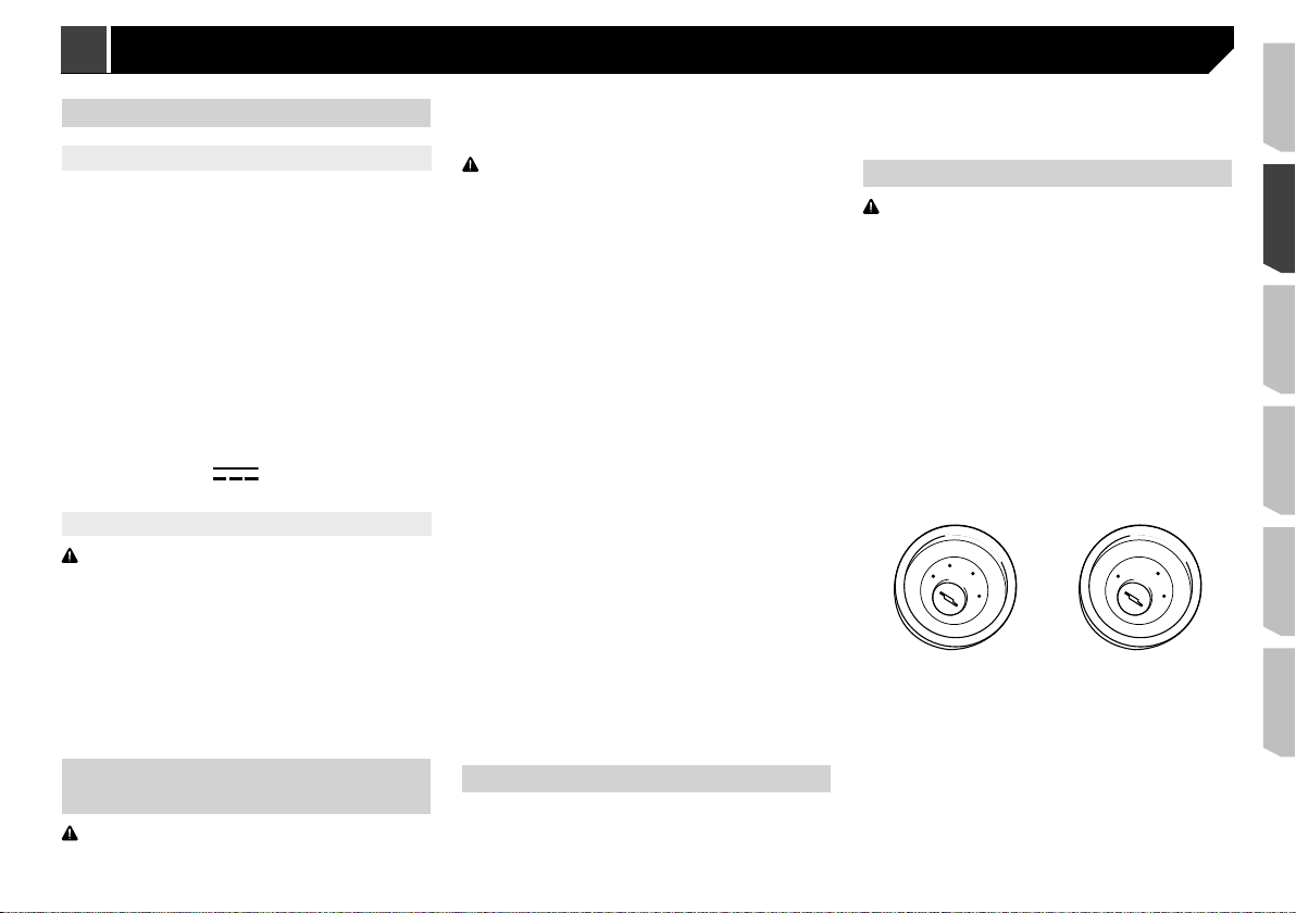
This product cannot be installed in a vehicle without ACC
(accessory) position on the ignition switch.
C
C
A
O
F
N
F
O
To avoid short-circuiting, cover the disconnected lead with
insulating tape. It is especially important to insulate all
unused speaker leads, which if left uncovered may cause a
short circuit.
For connecting a power amp or other devices to this product,
refer to the manual for the product to be connected.
S
T
A
R
T
ACC position No ACC position
O
F
N
F
O
S
T
A
R
T
Notice for the blue/white lead
When the ignition switch is turned on (ACC ON), a control signal
is output through the blue/white lead. Connect to an external
power amp’s system remote control terminal, the auto-aerial
relay control terminal, or the aerial booster power control terminal (max. 300 mA 12 V DC). The control signal is output through
the blue/white lead, even if the audio source is switched off.
Important
When this product is in “Power OFF” mode, the control signal
is also turned off. If “Power OFF” mode is cancelled, the
control signal is output again and the aerial is extended with
the auto aerial function (if the aerial is being used). Be careful
so that the extended aerial does not come into contact with
any obstacles.
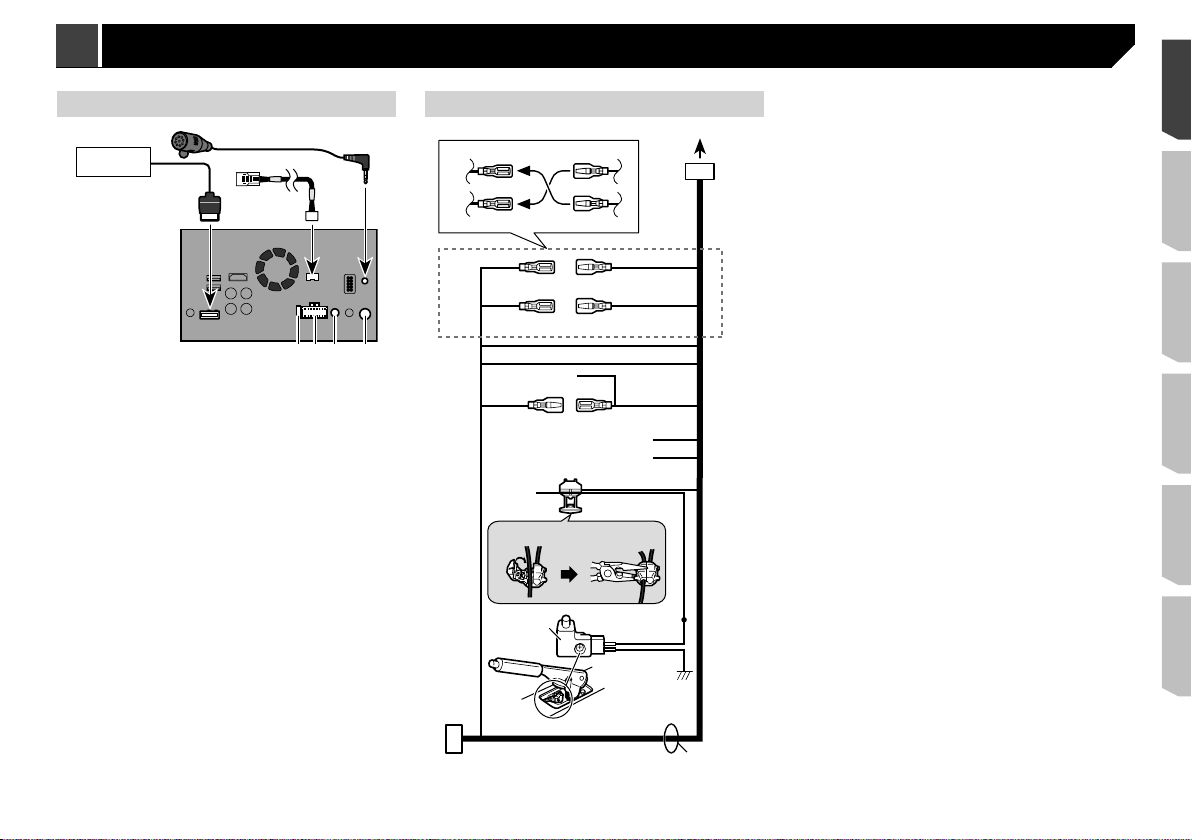
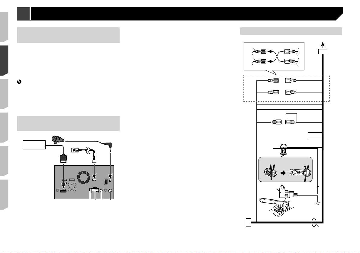
Rear panel (main terminals)
432
5
lk
9
7
8
Power cord
2
6
1
7
1 This product
2 Fuse (10 A)
3 Power supply
4 Wired remote input
Hard-wired remote control adapter can be connected (sold
separately).
Aerial jack
5
6 Vehicle Bus conversion cable 15.8 cm
Please refer to the instruction manual for the Vehicle Bus
adapter (sold separately).
Microphone 3 m
7
8 RGB cable (supplied with Navigation system)
9 Pioneer navigation system
Please contact your dealer to inquire about the connectable
navigation unit.
2*
8
9
a (5*)
g
1. 2.
3
54*6
i
1*
3*
4
c
b (6*)
1 To power supply
2 Depending on the kind of vehicle, the function of 2* and 4*
may be different. In this case, be sure to connect 1* to 4*
1
d
e
f
h
j
and 3* to 2*.
Yellow (2*)
3
Back-up (or accessory)
Yellow (1*)
4
Connect to the constant 12 V supply terminal.
Red (4*)
5
Accessory (or back-up)
Red (3*)
6
Connect to terminal controlled by ignition switch (12 V DC).
Connect leads of the same colour to each other.
7
8 Orange/white
To lighting switch terminal.
Black (ground)
9
To vehicle (metal) body.
Blue/white (5*)
a
The pin position of the ISO connector will differ depending
on the type of vehicle. Connect 5* and 6* when Pin 5 is an
aerial control type. In another type of vehicle, never connect
5* and 6*.
Blue/white (6*)
b
Connect to auto-aerial relay control terminal (max. 300 mA
12 V DC).
Blue/white
c
Connect to system control terminal of the power amp (max.
300 mA 12 V DC).
Violet/white
d
Of the two lead wires connected to the back lamp, connect
the one in which the voltage changes when the gear shift
is in the REVERSE (R) position. This connection enables
the unit to sense whether the car is moving forwards or
backwards.
Yellow/black
e
If you use an equipment with Mute function, wire this lead
to the Audio Mute lead on that equipment. If not, keep the
Audio Mute lead free of any connections.
Light green
f
Used to detect the ON/OFF status of the handbrake. This
lead must be connected to the power supply side of the
handbrake switch.
Connection method
g
1 Clamp the lead.
2 Clamp firmly with needle-nosed pliers.
h Power supply side
i Handbrake switch
j Earth side
k Speaker leads
White: Front left +
White/black: Front left –
3
Connection Connection
Grey: Front right +
Grey/black: Front right –
Green: Rear left +
Green/black: Rear left –
Violet: Rear right +
Violet/black: Rear right –
ISO connector
l
In some vehicles, the ISO connector may be divided into two.
In this case, be sure to connect to both connectors.
The position of the handbrake switch depends on the vehicle
p
model. For details, consult the vehicle Owner’s Manual or
dealer.
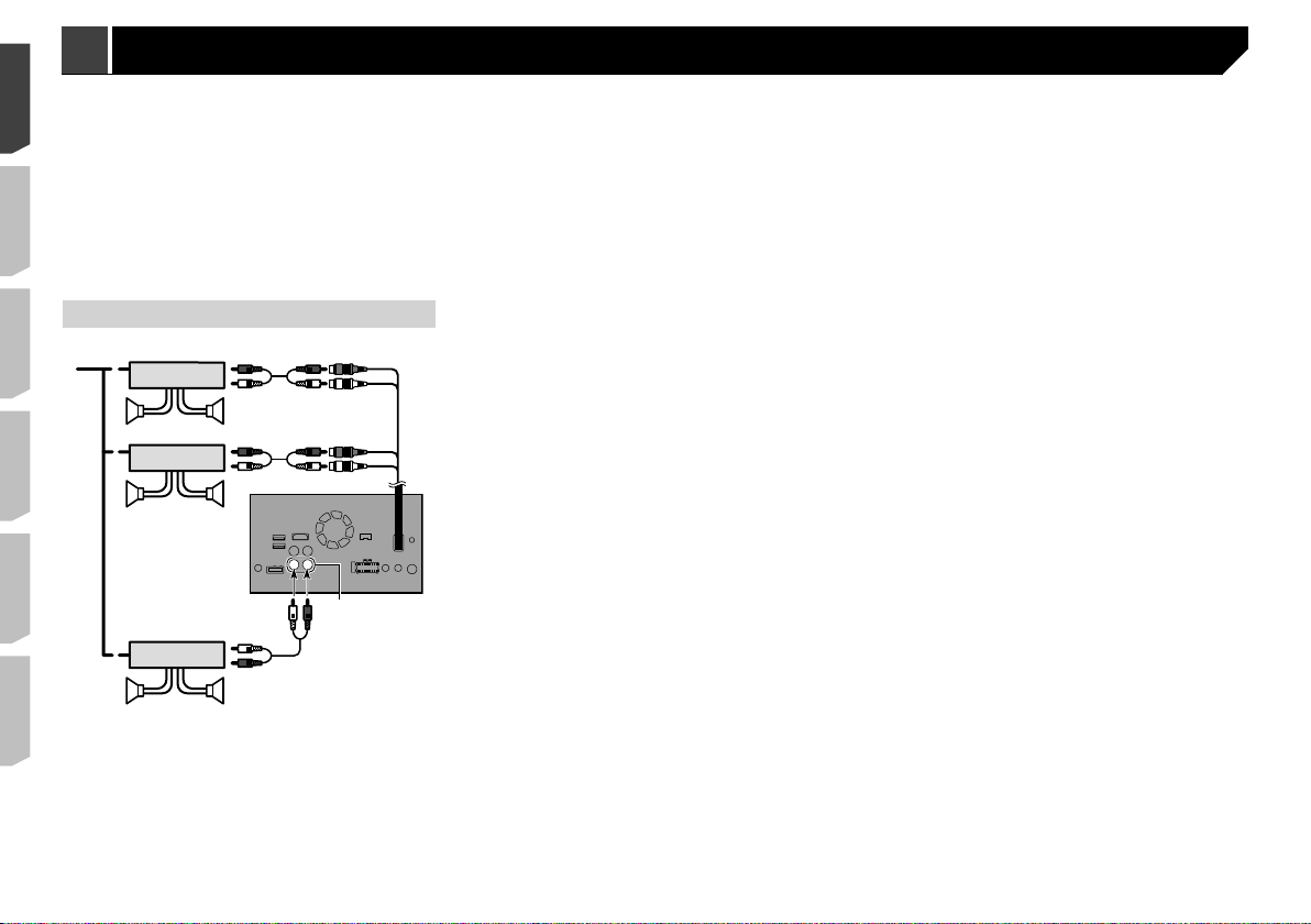
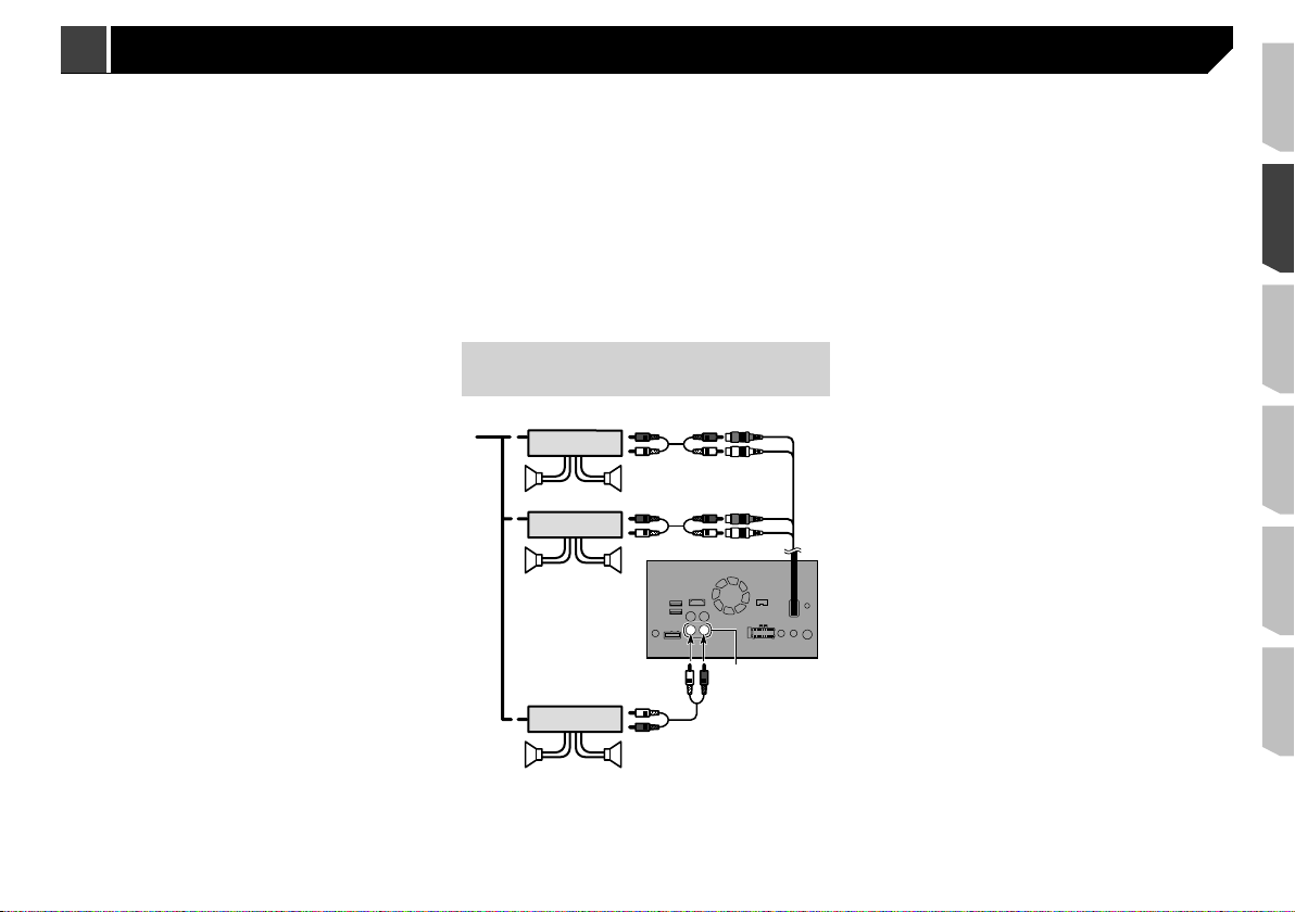
Power amp (sold separately)
1
3
2
1
6
55
3
2
6
8
3
2
1
9
1 System remote control
Connect to Blue/white cable (max. 300 mA 12 V DC).
Power amp (sold separately)
2
3 Connect with RCA cable (sold separately)
4 Rear outputs (REAR OUTPUT) 15 cm
5 Rear speaker
6 Front speaker
7 Front outputs (FRONT OUTPUT) 15 cm
8 This product
9 Subwoofer
a Subwoofer outputs
4
9
4
7
p You can change the RCA output of the subwoofer depending
on your subwoofer system.
Refer to the operation manual.
p The subwoofer output of this product is monaural.
a

Connecting an iPod / iPhone or an Android device
Find your device and the function you want to operate from the list below, and refer to the page for the connection.
Depending on the device, some functions may not be available.
p
iPhone (5, 5c, 5s, 6, 6 Plus)/iPod touch (5th generation)
iPod (audio)
Apple CarPlay
AppRadio Mode
iPhone 3GS/iPod touch (2nd, 3rd generation)/iPod classic (80GB, 160GB)/iPod nano (3rd, 4th, 5th, 6th generation)
iPod (audio)
iPod (video)
iPhone (4, 4s)/iPod touch (4th generation)
iPod (audio)
iPod (video)
AppRadio Mode
iPod nano (7th generation)
iPod (audio) Refer to Connecting via the USB port (iPhone) on page 6
Android device
AppRadio Mode
Android Auto
Refer to Connecting via the USB port (iPhone) on page 6
Refer to Connecting via the HDMI port (iPhone) on page 6
Refer to Connecting via the AUX input (iPhone) on page 6
Refer to Connecting via the RGB input (iPhone) on page 7
HDMI port
Refer to Connecting via the HDMI port (Android device) on page 7
MHL port
Refer to Connecting via the MHL port (Android device) on page 7
Refer to Connecting via the USB port (Android device) on page 7
5
5
1
3
4
2
1
2
3
7
65
4
4
7
5
1
Connection Connection
USB interface cable for iPod / iPhone (CD-IU52) (sold
iPhone and smartphone
For details on how to connect an external device using a
separately sold cable, refer to the manual for the cable.
For details concerning the connection, operations and
compatibility of iPhone, refer to Operation Manual.
For details concerning the connection and operations of
Android device, refer to Operation Manual.
In this chapter, iPhone and iPod touch will be referred to as
p
“iPhone”.
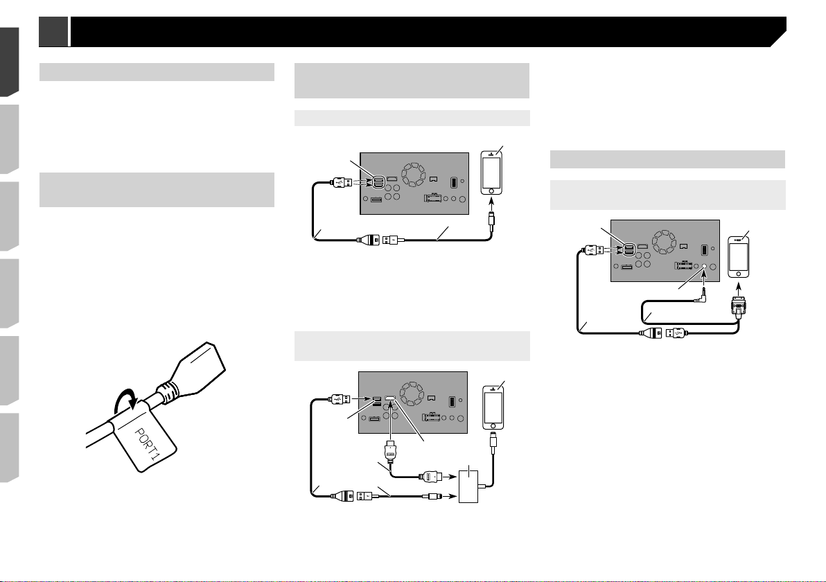
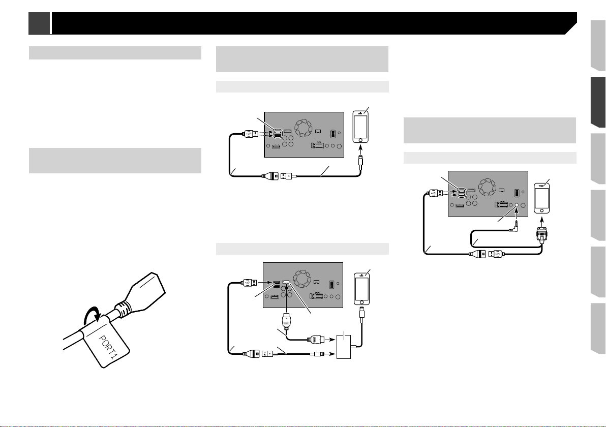
Attaching identication labels
to USB cables
Attach identification labels to USB cables before installing this
product in a vehicle.
1 Connect USB cables to the USB port 1 and 2 on
the rear of this product.
2 Attach the identification labels corresponding
to each port to the USB cables as illustrated
below.
Attach the “PORT 1” label to the USB cable connected to the
USB port 1.
Attach the “PORT 2” label to the USB cable connected to the
USB port 2.
iPhone with Lightning
connector
Connecting via the USB port (iPhone)
1
2
1 USB port 1/USB port 2
2 USB cable 1.5 m
3 USB interface cable for iPod / iPhone (CD-IU52) (sold
separately)
When using Apple CarPlay, connect the iPhone to USB
p
port 1.
iPhone with Lightning connector
4
Connecting via the HDMI port
(iPhone)
1
3
5
separately)
Lightning Digital AV Adapter (Apple Inc. products) (sold
6
separately)
iPhone with Lightning connector
7
p When you connect the High Speed HDMI® Cable, use the
lock tie to fix it securely.
Refer to Securing the High Speed HDMI® Cable on page 7
iPhone with 30-pin connector
Connecting via the AUX input
(iPhone)
2
3
1 USB port 1/USB port 2
2 AUX input
3 USB cable 1.5 m
4 USB interface cable for iPod / iPhone (CD-IU201V) (sold
separately)
iPhone with 30-pin connector
5
4
6
3
1 USB port 1
2 HDMI port
3 USB cable 1.5 m
4 High Speed HDMI® Cable (Type A - A) (supplied with
CD-IH202)
4
5
2
6
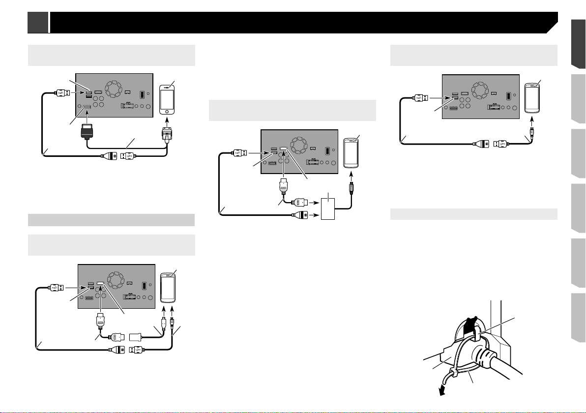
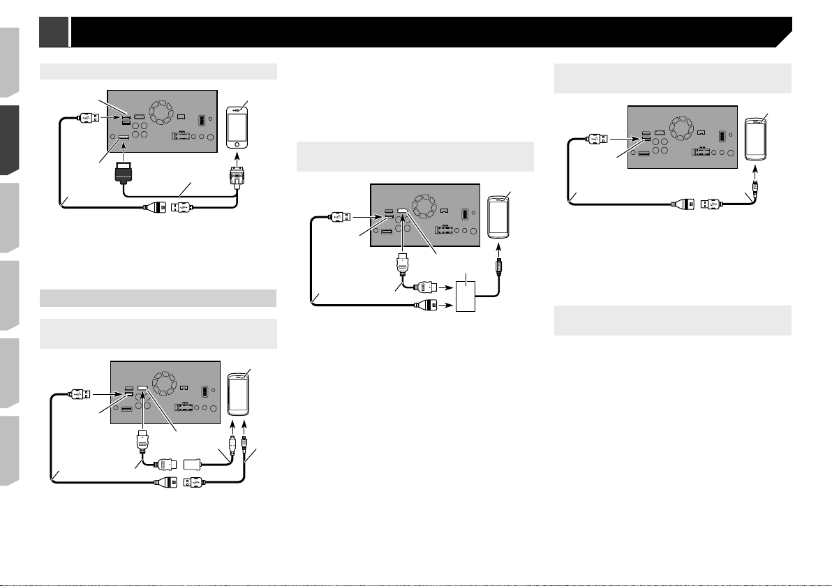
Connecting via the RGB input
5
6
6
4
1
3
(iPhone)
1
Adapter cable (HDMI Type A - D) (supplied with CD-AH200)
5
6 USB - micro USB cable (Type USB A - micro USB B) (sup-
plied with CD-AH200)
Android device
7
p When you connect the High Speed HDMI® Cable, use the
lock tie to fix it securely.
Refer to Securing the High Speed HDMI® Cable on page 7
Connecting via the USB port (Android
device)
2
3
1 USB port 1
2 RGB input
3 USB cable 1.5 m
4 USB interface cable for iPod / iPhone (CD-IU201S) (sold
separately)
iPhone with 30-pin connector
5
Android device
Connecting via the HDMI port
(Android device)
1
3
1 USB port 2
2 HDMI port
3 USB cable 1.5 m
4 High Speed HDMI® Cable (Type A - A) (supplied with
CD-AH200)
4
Connecting via the MHL port
(Android device)
4
1 USB port 2
1
2
5
3
1 USB port 2
2 HDMI port
3 USB cable 1.5 m
4 High Speed HDMI® Cable (Type A - A) (supplied with
CD-AH200)
MHL adapter (supplied with CD-AH200)
7
2
5
5
6 Android device
p When you connect the High Speed HDMI® Cable, use the
lock tie to fix it securely.
Refer to Securing the High Speed HDMI® Cable on page 7
4
2 USB cable 1.5 m
3 USB - micro USB cable (Type USB A - micro USB B) (sup-
Android device
4
For details on how to connect an external device using a
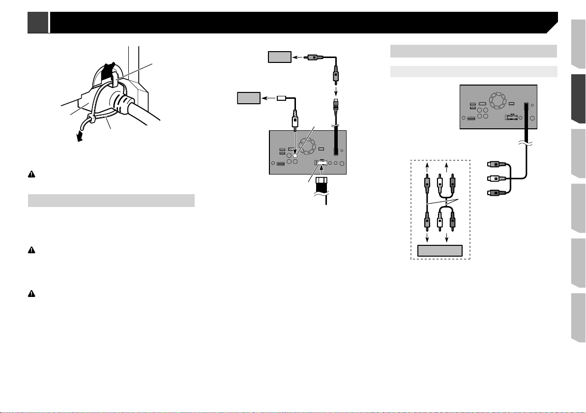
Securing the High Speed HDMI® Cable
Be sure to fix the High Speed HDMI® Cable with the lock tie,
when you connect the external device with the High Speed
HDMI
1 Insert the High Speed HDMI® Cable into the
2 Wrap the lock tie around the hook above the
1
2
plied with CD-MU200)
separately sold cable, refer to the manual for the cable.
®
Cable.
HDMI port.
HDMI port and the High Speed HDMI® Cable,
and then tighten it to secure the High Speed
®
Cable.
HDMI
3
2
7
1
67
9a
b
8
2
5
3
4
2
8
9
1
Connection Connection
1 Hook
2 Lock tie
3 High Speed HDMI® Cable
CAUTION
Do not tighten up the lock tie more than necessary.
Camera
When you use the rear view camera, the rear view image is
automatically switched from the video by moving the gearstick
to REVERSE (R). Camera View mode also allows you to check
what is behind you while driving.
WARNING
USE INPUT ONLY FOR REVERSE OR MIRROR IMAGE REAR
VIEW CAMERA. OTHER USE MAY RESULT IN INJURY OR
DAMAGE.
CAUTION
The screen image may appear reversed.
With the rear view camera you can keep an eye on
trailers, or back into a tight parking spot. Do not use for
entertainment purposes.
Objects in rear view may appear closer or more distant
than in reality.
The image area of full-screen images displayed while
backing or checking the rear of the vehicle may differ
slightly.
b
2
1
3
a
5
4
7
6
1 Rear view camera (ND-BC8) (sold separately)
2 To video output
3 RCA cable (supplied with ND-BC8)
4 This product
5 Brown (BC IN)
Power supply
6
7 Power cord
8 Violet/white (REVERSE-GEAR SIGNAL INPUT)
Refer to Power cord on page 3
Yellow (VIDEO INPUT) 15 cm
9
a RCA cable (sold separately)
b View camera (sold separately)
p Connect only the rear view camera to BC IN. Do not connect
any other equipment.
Some appropriate settings are required to use other view
p
cameras.
Refer to the operation manual.
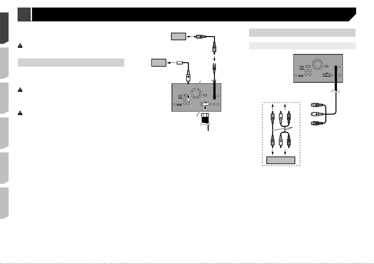
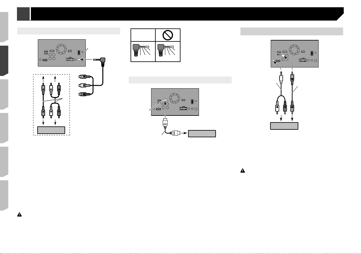
External video component
Using AV input
4
7
9
1 This product
2 Yellow (VIDEO INPUT) 15 cm
3 Red, white (AUDIO INPUT) 23 cm
4 To Yellow
5 To Red, white
6 RCA cables (sold separately)
7 To video output
8 To audio outputs
9 External video component (sold separately)
p The appropriate setting is required to use the external video
component.
Refer to the operation manual.
2
5
3
6
8
8
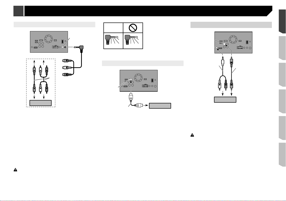
Using an AUX input
1
2
3
1
2
3
OK
Rear display
2
L
GVR
L : Left audio (White)
R : Right audio (Red)
L
V : Video (Yellow)
GRV
G : Ground
67
3
4
8
9a
b
1 This product
2 AUX input
3 Yellow
4 Red, white
5 Mini-jack AV cable (CD-RM10) (sold separately)
6 To Yellow
7 To Red, white
8 RCA cables (sold separately)
9 To video output
a To audio outputs
b External video component (sold separately)
p The appropriate setting is required to use the external video
component.
Refer to the operation manual.
p When connecting an external video component using a mini-
jack AV cable, use a separately sold AUX extension cable as
necessary.
CAUTION
Be sure to use a mini-jack AV cable (CD-RM10) (sold
separately) for wiring. If you use other cables, the wiring
position might differ resulting in disturbed images and
sounds.
Using an HDMI input
5
1
4
5
67
8
4
1 This product
2 HDMI port
3 High Speed HDMI® Cable (sold separately)
HDMI device (sold separately)
4
p When you connect the High Speed HDMI® Cable, use the
lock tie to fix it securely.
Refer to Securing the High Speed HDMI® Cable on page 7
1 This product
2 Yellow (V OUT)
Rear audio output
3
4 Mini pin plug cable (sold separately)
5 RCA cables (sold separately)
6 To audio inputs
7 To video input
8 Rear display with RCA input jacks (sold separately)
WARNING
NEVER install the rear display in a location that enables the
driver to watch video images while driving.
This product’s rear video output is for connection of a display
to enable passengers in the rear seats to watch the video
source.
9
1
1
2
Leave ample
space
1
1
1
Installation Installation
Precautions before installation
CAUTION
Never install this product in places where, or in a manner
that:
Could injure the driver or passengers if the vehicle
stops suddenly.
May interfere with the driver’s operation of the vehi-
cle, such as on the floor in front of the driver’s seat,
or close to the steering wheel or gearstick.
To ensure proper installation, be sure to use the sup-
plied parts in the manner specified. If any parts are
not supplied with this product, use compatible parts
in the manner specified after you have the parts’
compatibility checked by your dealer. If parts other
than supplied or compatible ones are used, they may
damage internal parts of this product or they may
work loose and the product may become detached.
Do not install this product where it may
(i) obstruct the driver’s vision,
(ii) impair the performance of any of the vehicle’s
operating systems or safety features, including
airbags, hazard lamp buttons or
(iii) impair the driver’s ability to safely operate the
vehicle.
Never install this product in front of or next to the
place in the dashboard, door, or pillar from which one
of your vehicle’s airbags would deploy. Please refer
to your vehicle’s owner’s manual for reference to the
deployment area of the frontal airbags.
Before installing
Consult with your nearest dealer if installation requires
drilling holes or other modifications of the vehicle.
Before making a final installation of this product, temporarily
connect the wiring to confirm that the connections are
correct and the system works properly.
Do not install this product in a position where the opening
of the LCD panel is obstructed by any obstacles, such as the
gearstick. Before installing this product, be sure to leave
sufficient space so that the LCD panel does not obstruct the
gearstick when it is fully opened. This may cause interference with the gearstick, or a malfunction of the mechanism
of this product.
Installation notes
Do not install this product in places subject to high tempera-
tures or humidity, such as:
10
Places close to a heater, vent or air conditioner.
Places exposed to direct sunlight, such as on top of the
dashboard.
Places that may be exposed to rain, such as close to the door
or on the vehicle’s floor.
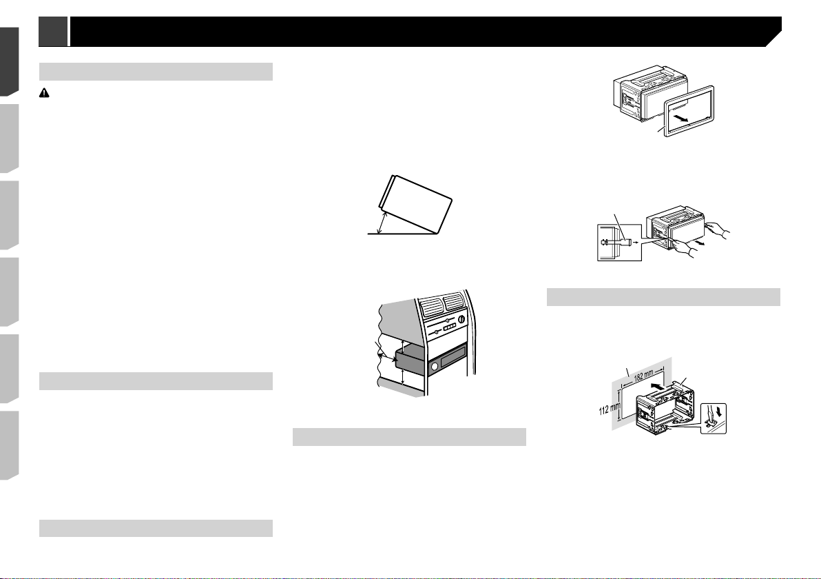
Install this product horizontally on a surface within 0 to
30 degrees tolerance (within 5 degrees to the left or right).
Improper installation of the product with the surface tilted
more than these tolerances increases the potential for errors
in the vehicle’s location display, and might otherwise cause
reduced display performance.
30°
When installing, to ensure proper heat dispersal when using
this product, make sure you leave ample space behind the
rear panel and wrap any loose cables so they are not blocking the vents.
5 cm
5 cm
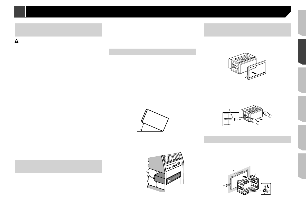
Before installing this product
1 Remove the trim ring.
Extend top and bottom of the trim ring outwards to remove the
trim ring.
1 Trim ring
2 Insert the supplied extraction keys into both
sides of the unit until they click into place.
3 Pull the unit out of the holder.
1 Extraction key
Installation with the holder
1 Install the holder into the dashboard.
2 Secure the mounting sleeve by using a screw-
driver to bend the metal tabs (90°) into place.
2
1 Dashboard
2 Holder
3 Install this product into the holder.
1
1 Dashboard
3
4
2
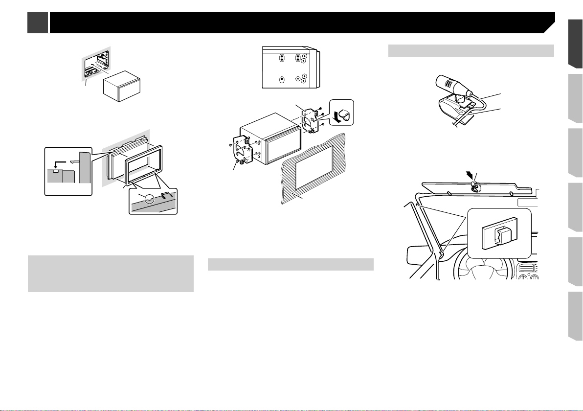
4 Attach the trim ring.
Mounting on the sun visor
1 Fit the microphone lead into the groove.
1
1
1
2
2
1 Microphone lead
2 Groove
2 Attach the microphone clip to the sun visor.
1
1 Trim ring
2 Groove
Attach the trim ring with the side with a groove facing
downward.
Installation using the screw
holes on the side of this
product
1 Fastening this product to the factory
radio-mounting bracket.
Position this product so that its screw holes are aligned with
the screw holes of the bracket, and tighten the screws at three
locations on each side.
Use either the truss head screws (5 mm × 8 mm) or flush
surface screws (5 mm × 9 mm), depending on the shape of the
bracket’s screw holes.
1 Factory radio-mounting bracket
2 If the pawl interferes with installation, you may bend it down
out of the way.
Dashboard or console
3
4 Truss head screw or flush surface screw
Be sure to use the screws supplied with this product.
Installing the microphone
Install the microphone in a place where its direction and dis-
tance from the driver make it easiest to pick up the driver’s
voice.
Be sure to turn off (ACC OFF) the product before connecting
the microphone.
Depending on the vehicle model, the microphone cable
length may be too short when you mount the microphone on
the sun visor. In such cases, install the microphone on the
steering column.
2
1 Microphone clip
2 Clamps
Use separately sold clamps to secure the lead where neces-
sary inside the vehicle.
Install the microphone on the sun visor when it is in the up
position. It cannot recognise the driver’s voice if the sun visor is
in the down position.
11
Installation Connexion
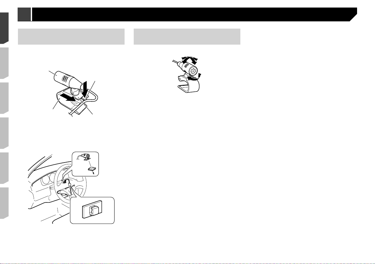
Installation on the steering
column
1 Detach the microphone base from the micro-
phone clip by sliding the microphone base
while pressing the tab.
1
2
4
1 Microphone
2 Tab
3 Microphone base
4 Microphone clip
2 Mount the microphone on the steering column.
2
3
1
Adjusting the microphone
angle
The microphone angle can be adjusted.
1 Double-sided tape
Install the microphone on the steering column, keeping it
away from the steering wheel.
Clamps
2
Use separately sold clamps to secure the lead where necessary inside the vehicle.
12
Précautions
Votre nouveau produit et ce manuel
N’utilisez pas ce produit, les applications ou la caméra de
rétrovisée en option (le cas échéant) si cela risque d’une
façon ou d’une autre de détourner votre attention quant à
la conduite en toute sécurité de votre véhicule. Observez
toujours les règles de sécurité au volant et suivez toutes les
réglementations de circulation en vigueur. Si vous éprouvez
des difficultés à utiliser ce produit ou à lire l’écran, garez
votre véhicule en lieu sûr et serrez le frein à main avant
d’effectuer les réglages nécessaires.
N’installez pas ce produit dans un endroit où il risque
(i) d’entraver la visibilité du conducteur,
(ii) d’altérer le fonctionnement de certains systèmes de commande des dispositifs de sécurité du véhicule, y compris les
airbags ou les boutons de feux de détresse, ou
(iii) d’empêcher le conducteur de conduire le véhicule en
toute sécurité.
Dans certains cas, il peut ne pas être possible d’installer
ce produit en raison du type de véhicule ou de la forme de
l’intérieur du véhicule.
Le symbole graphique situé sur le produit repré-
sente le courant continu.
Importantes mesures de sécurité
ATTENTION
Pioneer vous recommande de ne pas installer ce produit
vous-même. Ce produit doit être exclusivement installé
par un professionnel. Nous recommandons que seul le
personnel d’entretien Pioneer agréé, qui dispose d’une
formation et d’une expérience spéciales dans l’électronique mobile, configure et installe ce produit. N’INTERVENEZ JAMAIS SUR CE PRODUIT VOUS-MÊME.
L’installation ou l’entretien de ce produit et de ses
câbles de connexion peut vous exposer à un risque de
choc électrique ou à d’autres dangers, et peut entraîner
des dommages du produit non couverts par la garantie.
Précautions à prendre avant de
brancher le système
AVERTISSEMENT
N’essayez pas de modifier ou de désactiver le système
de verrouillage du frein à main, qui est installé pour
votre protection. La modification ou la désactivation du
système de verrouillage du frein à main peut entraîner
des blessures graves, voire mortelles.
ATTENTION
Attachez tous les fils avec des colliers ou des serre-
câbles. Ne laissez aucun fil à nu.
Ne raccordez pas directement le fil jaune conduc-
teur de ce produit à la batterie du véhicule. Si ce fil
conducteur est directement raccordé à la batterie, les
vibrations du moteur peuvent finir par user les câbles
au niveau de la jonction avec l’habitacle et provoquer
un défaut d’isolation. Si l’isolation du fil conducteur
jaune se déchire sous l’effet du contact avec des
pièces métalliques, il peut en résulter un court-circuit
extrêmement dangereux.
Il est extrêmement dangereux de laisser les câbles
s’enrouler autour de la colonne de direction ou du
levier de vitesse. Assurez-vous d’installer ce produit,
ses câbles et les fils de telle façon qu’ils n’obstruent
ni ne gênent la conduite.
Veillez à ce que la trajectoire des câbles et des fils
n’interfère pas avec les pièces en mouvement du
véhicule. Fixez les câbles de manière à les empêcher
d’être happés par, notamment, le volant, le levier de
vitesse, le frein à main, les glissières de siège, les
portes, ou tout autre élément de commande du véhicule.
La trajectoire des fils ne doit pas être exposée à des
températures élevées. Si l’isolation chauffe, les fils
risquent d’être endommagés, ce qui peut entraîner un
court-circuit ou un dysfonctionnement, et endommager de manière irrémédiable le produit.
Ne raccourcissez aucun fil conducteur. Vous risque-
riez autrement de provoquer un dysfonctionnement
du circuit de protection (porte-fusibles, résistance de
fusible ou filtre, etc.).
N’alimentez jamais d’autres produits électroniques en
coupant l’isolation du câble d’alimentation de ce produit et en exploitant le câble. La capacité du cordon
serait dépassée, ce qui provoquerait une surchauffe.
Avant d’installer ce produit
Utilisez ce produit uniquement avec une batterie de 12 V et
une mise à la masse du négatif. Sinon, cela pourrait entraîner un incendie ou un mauvais fonctionnement.
Afin d’éviter tout risque de court-circuit, débranchez le câble
de la borne négative (–) de la batterie avant de commencer la
pose.
Pour éviter toute détérioration
AVERTISSEMENT
Utilisez des haut-parleurs de plus de 50 W (puissance
d’entrée maximale) et entre 4 Ω et 8 Ω (valeur d’impédance). N’utilisez pas de haut-parleurs de 1 Ω à 3 Ω
avec ce produit.
Le fil noir correspond à la terre. Veuillez mettre à la terre ce
fil séparément de la terre des produits à courant élevé tels
que les amplificateurs de puissance. Ne mettez pas à la
terre plus d’un produit avec la terre d’un autre produit. Par
exemple, vous devez mettre à la terre les amplificateurs
séparément de la terre de ce produit. Raccorder des terres
ensemble peut provoquer un incendie et/ou des dommages aux produits si leurs terres se séparent.
Lors du remplacement du fusible, veillez à utiliser
seulement un fusible du calibre indiqué sur ce produit.
Ce produit ne peut pas être installé dans un véhicule qui
ne possède pas de position ACC (accessoire) sur le commutateur d’allumage.
C
C
A
O
F
N
F
O
Pour éviter les courts-circuits, recouvrez les fils déconnectés
de ruban isolant. Il est particulièrement important d’isoler
tous les fils conducteurs de haut-parleurs non utilisés pour
éviter tout risque de court-circuit.
Pour connecter un amplificateur de puissance ou d’autres
appareils à ce produit, reportez-vous au manuel du produit à
connecter.
S
T
A
R
T
Position ACC Pas de position ACC
O
F
N
F
O
S
T
A
R
T
13
432
5
lk
Connexion Connexion
Remarque concernant le l
bleu/blanc
Lorsque le commutateur d’allumage est sur Marche (ACC ON),
un signal de commande est émis par le biais du fil bleu/blanc.
Raccordez-le à une borne de commande à distance du système
d’amplificateur de puissance externe, à la prise de commande
de relais de l’antenne automatique du véhicule ou au terminal
de commande d’alimentation de l’amplificateur d’antenne (max.
300 mA 12 VCC). Le signal de commande est émis par le biais du
fil bleu/blanc, même si la source audio est désactivée.
Important
Lorsque ce produit est en mode “Power OFF”, le signal de
commande est également désactivé. Si le mode “Power OFF”
est annulé, le signal de commande est à nouveau émis et l’antenne est déployée à l’aide de la fonction d’antenne motorisée
(si l’antenne est utilisée). Veillez à ce que l’antenne déployée
n’entre pas en contact avec un obstacle.
Panneau arrière (bornes
principales)
9
7
8
6
1
6 Câble de conversion de bus du véhicule de 15,8 cm
Reportez-vous au manuel d’instructions de l’adaptateur du
bus du véhicule (vendu séparément).
Microphone 3 m
7
8 Câble RGB (fourni avec le système de navigation)
9 Système de navigation Pioneer
Veuillez contacter votre revendeur pour toute demande de
renseignements concernant les systèmes de navigation
pouvant être connectés.
Cordon d’alimentation
2
2*
7
8
9
g
1. 2.
3
54*6
a (5*)
i
1*
3*
4
c
b (6*)
d
e
f
1
h
j
1 Ce produit
2 Fusible (10 A)
3 Alimentation
4 Entrée télécommande câblée
Un adaptateur de télécommande câblée peut être raccordé
(vendu séparément).
Prise antenne
5
14
1
3
4
Vers alimentation
2 En fonction du type de véhicule, le fonctionnement de 2*
et de 4* peut être différent. Dans ce cas, assurez-vous de
raccorder 1* à 4* et 3* à 2*.
Jaune (2*)
3
Sauvegarde (ou accessoire)
Jaune (1*)
4
Raccordement à la borne d’alimentation 12 V constante.
Rouge (4*)
5
Accessoire (ou sauvegarde)
Rouge (3*)
6
Raccordement à la borne contrôlée par l’interrupteur d’allumage (12 V CC).
Raccordez les fils de même couleur les uns aux autres.
7
8 Orange/blanc
Vers la borne du commutateur d’éclairage.
Noir (terre)
9
Vers la carrosserie (métallique) du véhicule.
Bleu/blanc (5*)
a
La position des broches du connecteur ISO diffère en fonction du type de véhicule. Raccordez 5* et 6* si la broche 5
est de type commande de l’antenne. Dans un autre type de
véhicule, ne raccordez jamais 5* et 6*.
Bleu/blanc (6*)
b
Raccordement à la borne de commande du relais de l’antenne motorisée (max. 300 mA 12 V CC).
Bleu/blanc
c
Raccordement à la borne de commande du système de
l’amplificateur de puissance (max. 300 mA 12 V CC).
Violet/blanc
d
Des deux fils conducteurs raccordés au feu de recul, raccordez celui dans lequel la tension change quand le levier
de vitesse est en position REVERSE (R). Ce raccordement
permet à l’unité de détecter si la voiture de déplace en avant
ou en arrière.
Jaune/noir
e
Si vous utilisez un équipement avec une fonction de coupure
du son, branchez ce fil au fil Coupure audio de cet équipement. Sinon, ne connectez rien au fil Coupure audio.
Vert clair
f
Utilisé pour détecter le statut MARCHE/ARRÊT du frein à
main. Ce fil doit être raccordé au côté alimentation électrique du contacteur de frein à main.
Méthode de raccordement
g
1 Fixez le fil.
2 Fixez fermement avec une pince à bec effilé.
h Côté alimentation électrique
i Commutateur de frein à main
j Côté terre
k Fils des haut-parleurs
Blanc : Avant gauche +
Blanc/noir : Avant gauche –
Gris : Avant droit +
Gris/noir : Avant droit –
Vert : Arrière gauche +
Vert/noir : Arrière gauche –
Violet : Arrière droit +
Violet/noir : Arrière droit –
Connecteur ISO
l
Dans certains véhicules, le connecteur ISO peut être divisé
en deux. Dans ce cas, assurez-vous de raccorder les deux
connecteurs.
La position du levier de frein à main dépend du modèle de
p
véhicule. Pour en savoir plus, consultez le manuel du propriétaire du véhicule ou le revendeur.
Amplicateur de puissance
(vendu séparément)
1
2
1
6
1
9
1 Commande à distance du système
Raccordement au câble bleu/blanc (max. 300 mA 12 V CC).
Amplificateur de puissance (vendu séparément)
2
3 Raccordement avec un câble RCA (vendu séparément)
4 Sorties arrière (REAR OUTPUT) 15 cm
5 Haut-parleur arrière
55
3
7
2
6
8
a
3
2
9
6 Haut-parleur avant
7 Sorties avant (FRONT OUTPUT) 15 cm
8 Ce produit
9 Haut-parleur d’extrêmes graves
a Sorties haut-parleur d’extrêmes graves
p Vous pouvez changer la sortie RCA du haut-parleur d’ex-
trêmes graves en fonction de votre système de haut-parleur
d’extrêmes graves.
Reportez-vous au manuel de fonctionnement.
p La sortie du haut-parleur d’extrêmes graves de ce produit est
monaurale.
15

Connexion Connexion
Connexion d’un iPod / iPhone ou d’un appareil Android
Trouvez votre appareil et la fonction que vous voulez utiliser dans la liste ci-dessous, puis reportez-vous à la page concernant la connexion.
Selon l’appareil, certaines fonctions peuvent ne pas être disponibles.
p
iPhone (5, 5c, 5s, 6, 6 Plus)/iPod touch (5e génération)
iPod (audio)
Apple CarPlay
AppRadio Mode
iPhone 3GS/iPod touch (2e et 3e génération)/iPod classic (80 Go, 160 Go)/iPod nano (3e, 4e, 5e et 6e génération)
iPod (audio)
iPod (vidéo)
iPhone (4, 4s)/iPod touch (4e génération)
iPod (audio)
iPod (vidéo)
AppRadio Mode
iPod nano (7e génération)
iPod (audio) Reportez-vous à la page 17, Connexion via le port USB (iPhone)
Appareil Android
AppRadio Mode
Android Auto
Reportez-vous à la page 17, Connexion via le port USB (iPhone)
Reportez-vous à la page 17, Connexion via le port HDMI (iPhone)
Reportez-vous à la page 17, Connexion via l’entrée AUX (iPhone)
Reportez-vous à la page 18, Connexion via l’entrée RGB (iPhone)
Port HDMI
Reportez-vous à la page 18, Connexion via le port HDMI (appareil Android)
Port MHL
Reportez-vous à la page 18, Connexion via le port MHL (appareil Android)
Reportez-vous à la page 18, Connexion via le port USB (appareil Android)
16
iPhone et smartphone
4
7
5
1
Pour en savoir plus sur la connexion d’un périphérique
externe à l’aide d’un câble vendu séparément, reportez-vous
au manuel du câble.
Pour en savoir plus sur la connexion, le fonctionnement et
la compatibilité d’un iPhone, reportez-vous au Manuel de
fonctionnement.
Pour en savoir plus sur la connexion et le fonctionne-
ment de l’appareil Android, reportez-vous au Manuel de
fonctionnement.
Dans ce chapitre, iPhone et iPod touch sont appelés «
p
iPhone ».
iPhone avec connecteur
Lightning
Connexion via le port USB (iPhone)
1
Câble d’interface USB pour iPod / iPhone (CD-IU52) (vendu
5
séparément)
Adaptateur Lightning AV numérique (produits Apple Inc.)
6
(vendu séparément)
iPhone avec connecteur Lightning
7
p Lorsque vous connectez le câble HDMI® haute vitesse,
utilisez l’attache de blocage pour le fixer fermement.
Reportez-vous à la page 18, Fixation du câble HDMI® haute
vitesse
iPhone avec connecteur à
30 broches
Apposition d’étiquettes d’iden-
tication aux câbles USB
Apposez les étiquettes d’identification aux câbles USB avant
d’installer ce produit dans un véhicule.
1 Connectez les câbles USB aux ports USB 1 et 2
situés à l’arrière de ce produit.
2 Apposez les étiquettes d’identification corres-
pondant à chaque port aux câbles USB comme
illustré ci-dessous.
Apposez l’étiquette “PORT 1” au câble USB connecté au port
USB 1.
Apposez l’étiquette “PORT 2” au câble USB connecté au port
USB 2.
2
1 Port USB 1/Port USB 2
2 Câble USB 1,5 m
3 Câble d’interface USB pour iPod / iPhone (CD-IU52) (vendu
séparément)
Lors de l’utilisation de Apple CarPlay, connectez l’iPhone
p
au port USB 1.
iPhone avec connecteur Lightning
4
3
Connexion via le port HDMI (iPhone)
1
2
4
3
1 Port USB 1
2 Port HDMI
3 Câble USB 1,5 m
4 Câble HDMI® haute vitesse (type A - A) (fourni avec
CD-IH202)
5
6
Connexion via l’entrée AUX (iPhone)
2
3
1 Port USB 1/Port USB 2
2 Entrée AUX
3 Câble USB 1,5 m
4 Câble d’interface USB pour iPod / iPhone (CD-IU201V)
(vendu séparément)
iPhone avec connecteur à 30 broches
5
4
17
1
2
3
5
6
6
4
Connexion Connexion
Connexion via l’entrée RGB (iPhone)
1
2
3
1 Port USB 1
2 Entrée RGB
3 Câble USB 1,5 m
4 Câble d’interface USB pour iPod / iPhone (CD-IU201S)
(vendu séparément)
iPhone avec connecteur à 30 broches
5
Appareil Android
Connexion via le port HDMI (appareil
Android)
1
2
3
1 Port USB 2
2 Port HDMI
3 Câble USB 1,5 m
4 Câble HDMI® haute vitesse (type A - A) (fourni avec
CD-AH200)
Câble pour adaptateur (HDMI type A - D) (fourni avec
5
CD-AH200)
18
4
6 Câble USB - micro USB (type USB A - micro USB B) (fourni
avec CD-AH200)
Appareil Android
7
p Lorsque vous connectez le câble HDMI® haute vitesse,
utilisez l’attache de blocage pour le fixer fermement.
Reportez-vous à la page 18, Fixation du câble HDMI® haute
vitesse
Connexion via le port MHL (appareil
Android)
4
1
2
5
3
1 Port USB 2
2 Port HDMI
3 Câble USB 1,5 m
4 Câble HDMI® haute vitesse (type A - A) (fourni avec
7
CD-AH200)
Adaptateur MHL (fourni avec CD-AH200)
5
6 Appareil Android
p Lorsque vous connectez le câble HDMI® haute vitesse,
utilisez l’attache de blocage pour le fixer fermement.
Reportez-vous à la page 18, Fixation du câble HDMI® haute
vitesse
4
5
Connexion via le port USB (appareil
Android)
1
2
1 Port USB 2
2 Câble USB 1,5 m
3 Câble USB - micro USB (type USB A - micro USB B) (fourni
avec CD-MU200)
Appareil Android
4
Pour en savoir plus sur la connexion d’un périphérique
externe à l’aide d’un câble vendu séparément, reportez-vous
au manuel du câble.
3
Fixation du câble HDMI® haute
vitesse
Veillez à fixer le câble HDMI® haute vitesse à l’aide de l’attache
de blocage lorsque vous connectez un périphérique externe à
l’aide du câble HDMI
1 Insérez le câble HDMI® haute vitesse dans le
port HDMI.
2 Enroulez l’attache de blocage autour du cro-
chet situé au-dessus du port HDMI et du câble
HDMI
le câble HDMI
®
haute vitesse.
®
haute vitesse, puis serrez-la afin de fixer
®
haute vitesse.
1
3
2
8
9
1
2
1 Crochet
2 Attache de blocage
3 Câble HDMI® haute vitesse
ATTENTION
Ne serrez pas l’attache de blocage plus que nécessaire.
Caméra
Quand vous utilisez la caméra de rétrovisée, l’image de rétrovisée est automatiquement basculée depuis la vidéo en déplaçant
le levier de vitesse sur REVERSE (R). Le mode Vue Caméra
vous permet également de vérifier ce qui est derrière vous en
conduisant.
AVERTISSEMENT
UTILISEZ L’ENTRÉE UNIQUEMENT POUR LA MARCHE ARRIÈRE OU L’IMAGE INVERSÉE DE LA CAMÉRA DE RÉTROVISÉE. TOUTE AUTRE UTILISATION PEUT ENTRAÎNER DES
BLESSURES OU DES DOMMAGES.
L’image de l’écran peut apparaître inversée.
Avec la caméra de rétrovisée, vous pouvez surveiller une
ATTENTION
caravane ou vous garer en marche arrière dans un emplacement de stationnement étroit. Ne pas utiliser dans un
but de divertissement.
Les objets dans la caméra de rétrovisée peuvent paraître
plus proches ou plus éloignés qu’en réalité.
La zone d’image des images plein écran affichées en recu-
lant ou en vérifiant l’arrière du véhicule peut légèrement
différer.
b
2
1
3
a
5
4
7
6
1 Caméra de rétrovisée (ND-BC8) (vendue séparément)
2 Vers sortie vidéo
3 Câble RCA (fourni avec ND-BC8)
4 Ce produit
5 Marron (BC IN)
Alimentation
6
7 Cordon d’alimentation
8 Violet/blanc (REVERSE-GEAR SIGNAL INPUT)
Reportez-vous à la page 14, Cordon d’alimentation
Jaune (VIDEO INPUT) 15 cm
9
a Câble RCA (vendu séparément)
b Caméra de vision (vendue séparément)
p Raccordez uniquement la caméra de rétrovisée à BC IN. Ne
raccordez pas un autre équipement.
Certains réglages adaptés sont nécessaires pour utiliser
p
d’autres caméras de vision.
Reportez-vous au manuel de fonctionnement.
Composant vidéo externe
Utilisation de l’entrée AV
4
7
9
1 Ce produit
2 Jaune (VIDEO INPUT) 15 cm
3 Rouge, blanc (AUDIO INPUT) 23 cm
4 Vers jaune
5 Vers rouge, blanc
6 Câbles RCA (vendus séparément)
7 Vers sortie vidéo
8 Vers sorties audio
9 Composant vidéo externe (vendu séparément)
p Le réglage approprié est nécessaire pour utiliser le compo-
sant vidéo externe.
Reportez-vous au manuel de fonctionnement.
2
5
3
6
8
19
1
2
3
1
2
3
Connexion Installation
Utilisation d’une entrée AUX
67
3
4
8
9a
b
1 Ce produit
2 Entrée AUX
3 Jaune
4 Rouge, blanc
5 Câble AV mini-jack (CD-RM10) (vendu séparément)
6 Vers jaune
7 Vers rouge, blanc
8 Câbles RCA (vendus séparément)
9 Vers sortie vidéo
a Vers sorties audio
b Composant vidéo externe (vendu séparément)
p Le réglage approprié est nécessaire pour utiliser le compo-
sant vidéo externe.
Reportez-vous au manuel de fonctionnement.
p Lors de la connexion d’un élément vidéo externe à l’aide d’un
câble AV mini-jack, utilisez un câble d’extension AUX vendu
séparément si nécessaire.
ATTENTION
Veillez à utiliser un câble AV mini-jack (CD-RM10) (vendu
séparément) pour le raccordement. Si vous utilisez un autre
type de câble, la position du raccordement pourrait différer,
entraînant une déformation du son et des images.
OK
Écran arrière
2
L
GVR
Utilisation d’une entrée HDMI
5
1
1 Ce produit
2 Port HDMI
3 Câble HDMI® haute vitesse (vendu séparément)
Appareil HDMI (vendu séparément)
4
p Lorsque vous connectez le câble HDMI® haute vitesse,
utilisez l’attache de blocage pour le fixer fermement.
Reportez-vous à la page 18, Fixation du câble HDMI® haute
vitesse
L : Left audio (White)
R : Right audio (Red)
L
V : Video (Yellow)
GRV
G : Ground
4
5
67
8
4
1 Ce produit
2 Jaune (V OUT)
Sortie audio arrière
3
4 Câble à mini prise (vendu séparément)
5 Câbles RCA (vendus séparément)
6 Vers les entrées audio
7 Vers les entrées vidéo
8 Écran arrière avec prises d’entrée RCA (vendu séparément)
AVERTISSEMENT
N’installez JAMAIS l’écran arrière à un endroit où le conducteur pourrait voir des images vidéo pendant la conduite.
La sortie vidéo arrière de ce produit est prévue pour connecter
un écran afin de permettre aux passagers occupant les sièges
arrière de visionner la source vidéo.
20
Précautions à prendre avant
Laissez suffisamment
d’espace
1
1
1
l’installation
ATTENTION
N’installez jamais ce produit dans un endroit ou de telle
sorte qu’il :
Risque de blesser le conducteur ou les passagers en
cas d’arrêt brusque.
Puisse interférer avec les commandes de manœuvre
du conducteur tel que sur le plancher, en face du
siège conducteur, ou à proximité du volant ou du
levier de vitesse.
Pour garantir une installation correcte, assurez-vous
d’utiliser les pièces fournies de la façon spécifiée.
Si certaines pièces ne sont pas fournies avec cet
appareil, utilisez des pièces compatibles de la façon
spécifiée après avoir fait vérifier la compatibilité par
votre revendeur. Si d’autres pièces que les pièces
fournies ou compatibles sont utilisées, elles peuvent
endommager les pièces internes de ce produit ou
être mal assujetties, et le produit peut se détacher.
N’installez pas ce produit dans un endroit où il risque
(i) d’entraver la visibilité du conducteur,
(ii) d’altérer le fonctionnement de certains systèmes
de commande ou de dispositifs de sécurité du véhicule, y compris les airbags ou les boutons de feux de
détresse ou
(iii) d’empêcher le conducteur de conduire le véhicule en toute sécurité.
N’installez jamais ce produit devant ou à côté d’un
endroit sur le tableau de bord, une portière ou un
pilier, à partir duquel un des airbags du véhicule doit
se déployer. Veuillez vous reporter au mode d’emploi
du véhicule pour en savoir plus sur les zones de
déploiement des airbags frontaux.
Avant de procéder à
l’installation
Consultez le concessionnaire le plus proche si l’installation
nécessite de percer des trous ou toute autre modification du
véhicule.
Avant d’installer ce produit définitivement, connectez
le câblage provisoirement pour vous assurer que les
connexions sont correctes et que le système fonctionne
normalement.
N’installez pas ce produit dans une position où l’ouverture
du panneau LCD serait gênée par des obstacles, le levier de
vitesse par exemple. Avant d’installer ce produit, veillez à
laisser un espace suffisant afin que le panneau LCD ne gêne
pas l’utilisation du levier de vitesse lorsqu’il est complètement ouvert. Ceci pourrait entraîner une interférence avec le
levier de vitesse ou un dysfonctionnement du mécanisme de
ce produit.
Remarques sur l’installation
N’installez pas ce produit dans un endroit soumis à des
températures élevées ou à l’humidité. Par exemple :
À proximité du chauffage, de la ventilation ou de la
climatisation.
En plein soleil, comme sur le dessus du tableau de bord.
Endroits susceptibles d’être exposés à la pluie, près de la
portière ou sur le plancher du véhicule par exemple.
Installez ce produit horizontalement sur une surface avec
une tolérance de 0 à 30 degrés (dans une plage de 5 degrés
vers la gauche ou la droite). Une mauvaise installation du
produit avec une inclinaison de la surface supérieure à cette
marge de tolérance risque d’accroître le potentiel d’erreurs
dans l’affichage de l’emplacement, et de réduire les performances d’affichage.
30°
Lors de l’installation, laissez suffisamment d’espace derrière
le panneau arrière pour permettre une dissipation correcte
de la chaleur et enroulez les câbles volants de façon qu’ils
ne bloquent pas les orifices d’aération.
5 cm
5 cm
Avant l’installation de ce
produit
1 Retirez l’anneau de garniture.
Étirez vers l’extérieur la partie supérieure et inférieure de l’anneau de garniture pour le retirer.
1 Anneau de garniture
2 Insérez les clés de démontage fournies dans les
deux côtés de l’appareil jusqu’au déclic.
3 Tirez l’appareil hors du support.
1 Clé de démontage
Installation avec le support
1 Installez le support dans le tableau de bord.
2 Fixez le manchon de montage en utilisant un
tournevis pour courber les pattes métalliques
(90°) en place.
2
1 Tableau de bord
2 Support
21
 Loading...