


|
CE132/all ,--G,R/all |
|
Mini System |
|
|
|
|
|
Service
Service
Service |
Manual |
||||||||
TABLE OF |
CONTENTS |
|
|
|
|
|
|
|
|
DISMANTLING INSTRUCTIONS |
2 MAIN PCB COMPONENT LAYOUT |
8-9 |
|
|
|
|
|
||
|
|
|
|
|
|||||
RECORDABLE REWRITABLE |
|||||||||
|
|
|
|
|
|||||
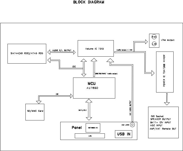
BLOCK DIAGRAM........................................................................ |
3 |
PANEL PCB COMPONENT LAYOUT......................................... |
10-11 |
|
|
|
|
|
|
WIRING DIAGRAM...................................................................... |
4 |
SET EXPLODER VIEW DRAWING |
12 |
|
|
|
|
|
|
.............................................CIRCUIT DIAGRAM MAIN BOARD |
5-6 |
|
|
|
|
|
|||
CIRCUIT DIAGRAM PANEL BOARD |
7 |
TROUBLE SHOOTING |
|
13-14 |
|
|
|
|
|
................................................................... |
|
|
|
|
|
||||
|
|
|
|
|
|
|
|
|
|
Version1.0
2012-4-26
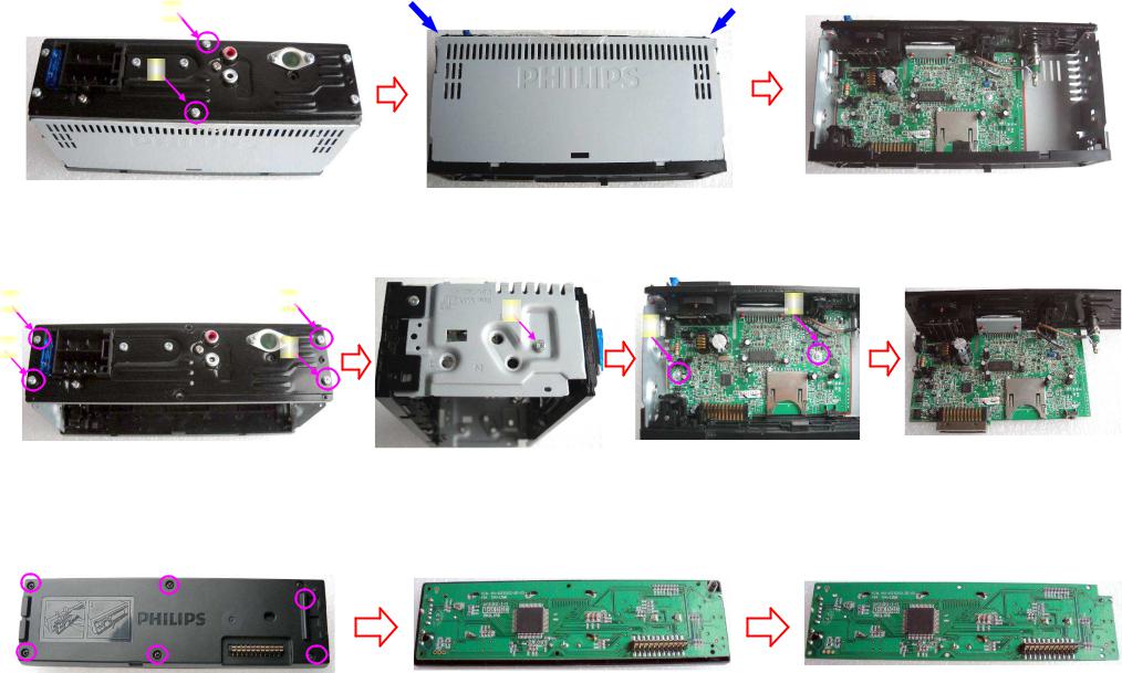
0(7+2' 2) ',6$66(0%/,1* &(
The procedure of disassembling the unit
1.Remove A, B screws in the back cover as below picture showed; Use tweezer to prize up top cover as the blue arrow direction which showed as below picture and remove
the top cover
A
B
5HPRYH $ % VFUHZV LQ WKH EDFN FRYHU |
|
8VH WZHH]HU WR SUL]H XS WRS FRYHU |
5HPRYH WKH WRS FRYHU |
2.) Remove the four screws in C,D,E,F position in the heat sink, then remove the G screw in left side of the unit and the H, I screws which were for fixing the main board; remove the main board
C E G I
H
D F
5HPRYH WKH IRXU VFUHZV LQ WKH KHDW VLQN 5HPRYH WKH * VFUHZ LQ OHIW VLGH RI WKH XQLW 5HPRYH WKH WZR VFUHZV ZKLFK ZHUH IRU IL[LQJ WKH PDLQ ERDUG 5HPRYH PDLQ ERDUG
The procedure of disassembling the panel
5HPRYH WKH VL[ VFUHZV LQ EDFN SDQHO DQG VHSDUDWH WKH EDFN SDQHO IURP IURQW SDQHO 7DNH RXW WKH EDFN SDQHO DQG WKHQ WDNH RXW 3&% ERDUG
5HPRYH WKH VL[ VFUHZV |
6HSDUDWH WKH EDFN SDQHO IURP IURQW SDQHO |
7DNH RXW 3&% ERDUG |
2
3
Wiring Diagram
4

CIRCUIT DIAGRAM -MAIN BOARD
5
 Loading...