


WV-S1131
WV-S1131
【1】
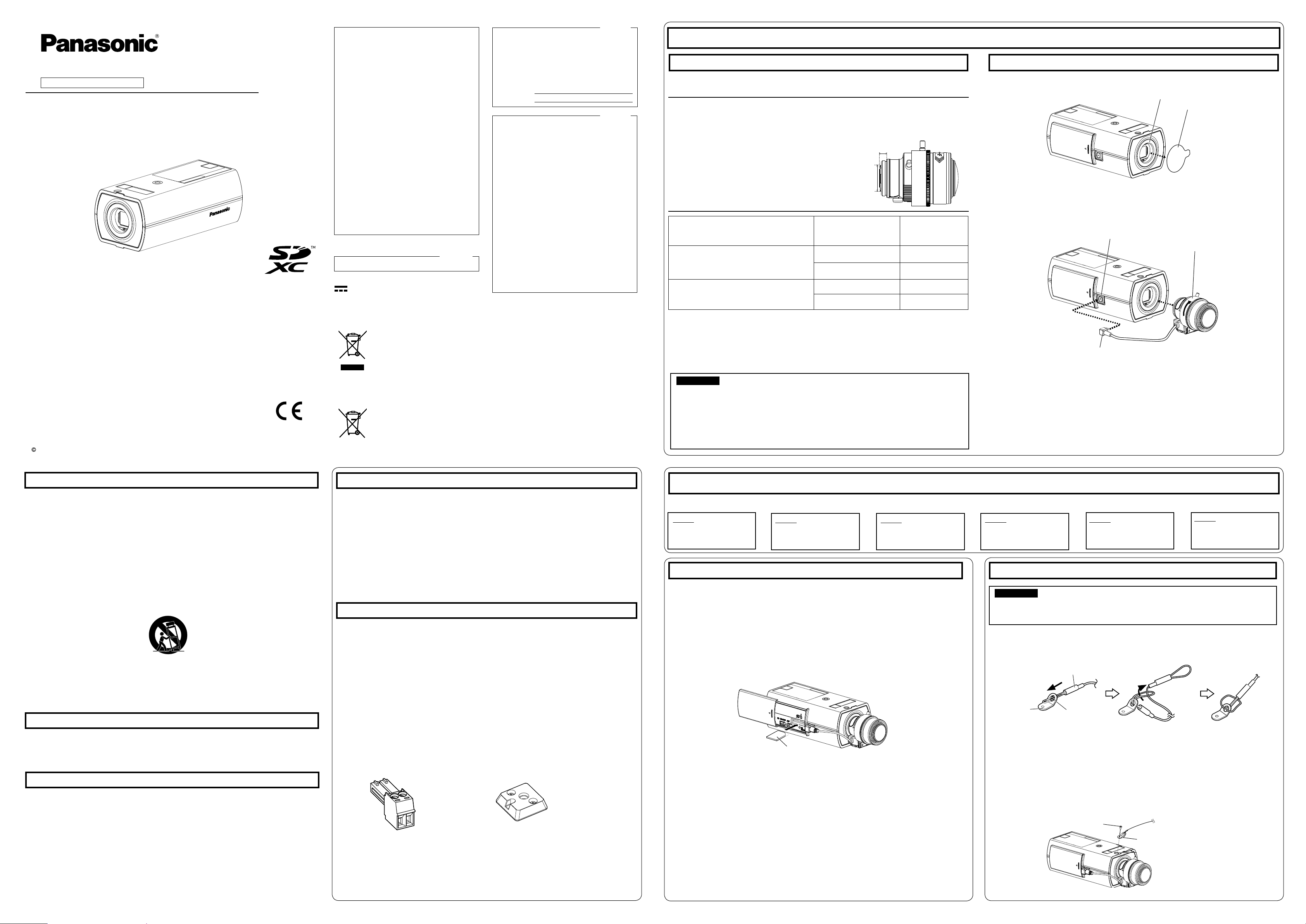
Remove the cover fi lm attached to the lens mounting hole of the camera.
Installation method Recommended screw
Minimum pull-out
strength
(per 1 pc.)
For mounting on ceiling
Mount bracket: approx. 260
g {0.57 lbs}
camera: 350
g {0.77lbs}
M6 or M8 screws × 4
*1
562 N {126 lbf}
*2
M4
×
1 (for the safety wire)
24.5 N {5.5 lbf}
For mounting on wall
Mount bracket: approx. 420 g {0.93 lbs}
camera: 350
g {0.77lbs}
M6 or M8 screws × 4
*1
724 N {163 lbf}
*2
M4
×
1 (for the safety wire)
24.5 N {5.5 lbf}
*1 The number of required screws or anchor bolts varies depending on the specifi cations of the
mount bracket (locally procured). Refer to the operating instructions of the mount bracket (locally
procured) for information about how to mount the mount bracket.
*2 Make sure that the screws or anchor bolts separately procured when locally procuring a mount
bracket for the ceiling or wall are capable of supporting the total weight (including the moment
force when mounting to a wall).
Step1 Insert an SD memory card
Installation
Step1
Insert an SD memory
card.
Step2
Attach the safety wire
Step3
Mount the camera
Step4
Making connections
⇨
⇨
⇨
⇨
Step6
Configure the network
settings
【2】
Slowly rotate the lens clockwise to mount the lens and connect the lens
cable to the ALC lens connector of the camera.
Preparations
⇨
Step5
Adjust the camera
【1】Engage the safety wire (accessory) with the wire engaging hole.
【2】Secure the safety wire lug (accessory) to the camera mount screw hole
with the wire lug fi xing screw (accessory).
(Recommended tightening torque: 0.39 N·m {0.29 lbf·ft})
Step2 Attach the safety wire (accessory)
IMPORTANT:
When securing the camera using a separately procured bracket, use the fi xing screw (M4,
locally procured), and the safety wire, washer, and spring washer
(accessories).
−
+
Tripod mount base
Power cable plug
IMPORTANT:
The installation area shall be strong enough to hold the camera and camera mount bracket.
The camera mount bracket (locally procured) shall be mounted on the foundation part of the
construction or a part with adequate strength.
Select screws according to the material of the location that the camera will be mounted to.
In this case, wood screws and nails should not be used.
If the mounting location such as plaster board is too weak to support the total weight, the
area shall be sufficiently reinforced.
Other items that are needed (not included) Mount the lens to the camera
【2】
Close the slide cover on the side of the camera.
Remove the camera using the reverse order of the installation procedures.
WV-S1131
Network Camera
Model No. WV-S1132 / WV-S1131
WV-S1112 / WV-S1111
Installation Guide
Included Installation Instructions
(Please purchase the recommended lens separately.)
Before attempting to connect or operate this product, please read these instructions carefully and
save this manual for future use.
For information about the basic information about this product, refer to the installation instructions
on the provided CD-ROM. For information about how to perform the settings and how to operate
the camera, refer to the Operating Instructions on the provided CD-ROM.
The model number is abbreviated in some descriptions in this manual.
For U.S. and Canada:
Panasonic System Communications
Company of North America,
Unit of Panasonic Corporation
of North America
www.panasonic.com/business/
For customer support, call 1.800.528.6747
Two Riverfront Plaza, Newark, NJ 07102-5490
Panasonic Canada Inc.
5770 Ambler Drive, Mississauga,
Ontario, L4W 2T3 Canada
(905)624-5010
www.panasonic.ca
For Europe and other countries:
Panasonic Corporation
http://www.panasonic.com
Panasonic System Networks Co., Ltd.
Fukuoka, Japan
Authorised Representative in EU:
Panasonic Testing Centre
Panasonic Marketing Europe GmbH
Winsbergring 15, 22525 Hamburg, Germany
Panasonic System Networks Co., Ltd. 2016
avs0916-2126 PGQX2078XA Printed in China
The model number and serial number of this
product may be found on the surface of the unit.
You should note the model number and serial
number of this unit in the space provided and
retain this book as a permanent record of your
purchase to aid identification in the event of
theft.
Model No.
Serial No.
NOTE: This equipment has been tested and found
to comply with the limits for a Class A digital
device, pursuant to Part 15 of the FCC Rules.
These limits are designed to provide reasonable
protection against harmful interference when the
equipment is operated in a commercial environ-
ment. This equipment generates, uses, and can
radiate radio frequency energy and, if not installed
and used in accordance with the instruction man-
ual, may cause harmful interference to radio com-
munications.
Operation of this equipment in a residential area is
likely to cause harmful interference in which case
the user will be required to correct the interfer-
ence at his own expense.
FCC Caution: To assure continued compliance,
(example - use only shielded interface cables
when connecting to computer or peripheral devic-
es). Any changes or modifications not expressly
approved by the party responsible for compliance
could void the user’s authority to operate this
equipment.
For U.S.A.
For U.S.A.
CAN ICES-3(A)/NMB-3(A)
For Canada
WARNING:
• To prevent injury, this apparatus must be secure-
ly attached to the wall/ceiling in accordance with
the installation instructions.
• To prevent fire or electric shock hazard, do not
expose this apparatus to rain or moisture.
• The apparatus should not be exposed to drip-
ping or splashing.
• All work related to the installation of this product
should be made by qualified service personnel
or system installers.
• The installation shall be carried out in accor-
dance with all applicable installation rules.
• The connections should comply with local elec-
trical code.
• Batteries (battery pack or batteries installed)
shall not be exposed to excessive heat such as
sunlight, fire or the like.
CAUTION:
• Any changes or modifications not expressly
approved by the party responsible for compli-
ance could void the user’s authority to operate
the equipment.
• The network camera is only intended for a con-
nection to an ethernet or PoE network without
routing to the outside plant.
Disposal of Old Equipment and Batteries
Only for European Union and countries with recycling systems
These symbols on the products, packaging, and/or accompanying documents mean that used
electrical and electronic products and batteries must not be mixed with general household waste.
For proper treatment, recovery and recycling of old products and used batteries, please take them
to applicable collection points in accordance with your national legislation.
By disposing of them correctly, you will help to save valuable resources and prevent any potential
negative effects on human health and the environment.
For more information about collection and recycling, please contact your local municipality.
Penalties may be applicable for incorrect disposal of this waste, in accordance with national
legislation.
Note for the battery symbol (bottom symbol)
This symbol might be used in combination with a chemical symbol. In this case it complies with the
requirement set by the Directive for the chemical involved.
Important safety instructions
1) Read these instructions.
2) Keep these instructions.
3) Heed all warnings.
4) Follow all instructions.
5) Do not use this apparatus near water.
6) Clean only with dry cloth.
7)
Do not block any ventilation openings. Install in accordance with the manufacturer's instructions.
8)
Do not install near any heat sources such as radiators, heat registers, stoves, or other apparatus (including
amplifiers) that produce heat.
9) Only use attachments/accessories specified by the manufacturer.
10) Use only with the cart, stand, tripod, bracket, or table specified by the manufacturer, or sold with the
apparatus. When a cart is used, use caution when moving the cart/apparatus combination to avoid injury
from tip-over.
S3125A
11) Unplug this apparatus during lightning storms or when unused for long periods of time.
12) Refer all servicing to qualified service personnel. Servicing is required when the apparatus has been dam-
aged in any way, such as power-supply cord or plug is damaged, liquid has been spilled or objects have
fallen into the apparatus, the apparatus has been exposed to rain or moisture, does not operate normally,
or has been dropped.
Troubleshooting
Before requesting service, refer to the Important Information (included in the CD-ROM) and
“Troubleshooting” in the Operating Instructions (included in the CD-ROM) and confirm the
trouble.
Open Source Software
This product contains open source software licensed under GPL (GNU General Public License),
LGPL (GNU Lesser General Public License), etc.
Customers can duplicate, distribute and modify the source code of the software under license of
GPL and/or LGPL.
Refer to the “readme.txt” file on the provided CD-ROM for further information about open source
software licenses and the source code.
Please note that Panasonic shall not respond to any inquiries regarding the contents of the source
code.
About the user manuals
Product documentation is composed of the following documents.
• Installation Guide (this document): Explains installation, mounting, cable connections, and adjusting the
fi eld of view. This manual uses the WV-S1131 as an example in the explanations.
• Important Information (included in the CD-ROM):
Provides basic information about the product.
• Operating Instructions (included in the CD-ROM): Explains how to perform the settings and how to
operate this camera.
Adobe
®
Reader
®
is required to read these operating instructions on the provided CD-ROM.
When the Adobe Reader is not installed on the PC, download the latest Adobe Reader from the Adobe web site
and install it.
The external appearance and other parts shown in this manual may differ from the actual product within the
scope that will not interfere with normal use due to improvement of the product.
Standard accessories
Installation Guide (this document) ........................1 set
IMPORTANT SAFETY INSTRUCTIONS ............... 1 pc.
Warranty card*
1
...................................................1 set
CD-ROM*
2
.......................................................... 1 pc.
Code label*
3
........................................................ 1 pc.
*1 This product comes with several types of warranties. Each warranty is only applicable to the products pur-
chased in the regions indicated on the relevant warranty.
*2 The CD-ROM contains the operating instructions and different kinds of tool software programs.
*3 This label may be required for network management. Use caution not to lose this label.
Tripod mount base*
4
........................................... 1 pc.
Power cable plug ................................................ 1 pc.
Safety wire lug
..................................................... 1 pc.
Wire lug fixing screws
(M2.5 × 8 mm {5/16 inches}) .......................2 pcs.
(of them, 1 for spare)
Safety wire .......................................................... 1 pc.
Washer ............................................................... 1 pc.
Spring washer .................................................... 1 pc.
The following parts are used during installation procedures.
Note:
The lens section is not included with the camera. Refer to our website
(http://security.panasonic.com/support/info/) for further information about the
compatible lens.
Lens mounting hole
Cover fi lm
Lens cable
Lens
(compatible)
ALC lens connector
The installation tasks are explained using 6 steps.
When using an SD memory card, go through the following procedure before in-
stalling the camera.
When removing an SD memory card, reverse the procedure.
Refer to the Operating Instructions on the provided CD-ROM for further information about the SD
memory card settings.
【1】Open the slide cover on the side of the camera, insert an SD memory card
fully into the SD memory card slot until a click is heard.
Insert the SD memory card with its label facing up.
SD memory card
* Label face upward
Safety wire (accessory)
Wire engaging hole
Safety wire lug
(accessory)
Wire lug fi xing screw
(accessory)
Fixing screw hole
Safety wire lug (accessory)
*4 For further information about Tripod mount base, refer to the Important Information on the provided CD-ROM.
Prepare the required parts for each installation method before starting the installation. The following
are the requirements for the various installation methods.
* When using a lens made by other companies,
use a lens that has a protruded portion from
the mount face of ø20 mm {25/32 inches} or
less and a protruded portion from the fl ange
face of 4.5 mm {5/32 inches} or less. Lenses
without a focus adjustment mechanism and
zoom lenses cannot be used.
Protruded portion from fl ange face:
4.5 mm {5/32 inches} or less
Protruded portion
from mount face:
ø20 mm
{25/32inches}
or less
: Direct current symbol
 Loading...