


Operating Instructions
Network Camera
Model No. WV-SP105, WV-SP102
WV-SP105E, WV-SP102E
-SP105 |
-SP102 |
WV |
WV |
WV-SP105 |
WV-SP102 |
Before attempting to connect or operate this product,
please read these instructions carefully and save this manual for future use.
The model number is abbreviated in some descriptions in this manual.

CONTENTS
Preface......................................................................... |
3 |
About the user manuals........................................... |
3 |
About notations....................................................... |
3 |
Trademarks and registered trademarks................... |
3 |
Abbreviations........................................................... |
3 |
Viewer software........................................................ |
4 |
Monitor images on a PC.............................................. |
5 |
Monitor images from a single camera..................... |
5 |
About the "Live" page.............................................. |
7 |
Monitor images from multiple cameras................... |
9 |
Action at an alarm occurrence................................... |
10 |
Alarm type.............................................................. |
10 |
Action at an alarm occurrence............................... |
10 |
Transmit images onto an FTP server......................... |
11 |
Transmit an alarm image at an alarm occurrence |
|
(Alarm image transmission).................................... |
11 |
Transmit images at a designated interval or |
|
period (FTP periodic image transmission)............. |
11 |
About the network security........................................ |
12 |
Equipped security functions.................................. |
12 |
Display the setup menu from a PC............................ |
13 |
How to display the setup menu............................. |
13 |
How to operate the setup menu............................ |
14 |
About the setup menu window.............................. |
15 |
Configure the basic settings of the camera [Basic]... |
17 |
Configure the basic settings [Basic]...................... |
17 |
Configure the settings relating to images [Image]..... |
19 |
Configure the settings relating to the aspect ratio |
|
[JPEG/H.264]......................................................... |
19 |
Configure the settings relating to JPEG images |
|
[JPEG/H.264]......................................................... |
19 |
Configure the settings relating to H.264 images |
|
[JPEG/H.264]......................................................... |
20 |
Configure the settings relating to image quality, |
|
extra zoom and the privacy zone |
|
[Image/Privacy]...................................................... |
23 |
Configure the settings relating to image quality |
|
("Image adjust" setup menu).............................. |
24 |
Set mask areas................................................... |
27 |
Extra zoom setting (Extra zoom setup menu)..... 28 |
|
Configure the settings relating to the privacy |
|
zone (Privacy zone setup menu)......................... |
29 |
Configure the multi-screen settings [Multi-screen].... |
30 |
Configure the alarm settings [Alarm].......................... |
31 |
Configure the settings relating to the alarm action |
|
[Alarm].................................................................... |
31 |
Configure the settings relating to the alarm image |
|
[Alarm].................................................................... |
32 |
Configure the VMD settings [VMD area]................ |
33 |
Set the VMD areas [VMD area].............................. |
35 |
Configuration of the settings relating to the mail |
|
notification [Notification]........................................ |
36 |
Configure the settings relating to Panasonic |
|
alarm protocol [Notification]................................... |
37 |
Configure the settings relating to the authentication |
|
[User mng.]................................................................. |
38 |
Configure the settings relating to the user |
|
authentication [User auth.]..................................... |
38 |
Configure the settings relating to the host |
|
authentication [Host auth.]..................................... |
39 |
Configure the settings relating to the priority |
|
stream [System]..................................................... |
40 |
Configure the settings of the servers [Server]............ |
41 |
Configure the settings relating to the mail server |
|
[Mail]....................................................................... |
41 |
Configure the settings relating to the FTP server |
|
[FTP]....................................................................... |
42 |
Configure the settings relating to the NTP server |
|
[NTP]...................................................................... |
43 |
Configure the network settings [Network]................. |
44 |
Configure the network settings [Network]............. |
44 |
Configure the settings relating to DDNS |
|
[DDNS]................................................................... |
47 |
Configure the settings relating to SNMP |
|
[SNMP]................................................................... |
48 |
Configure the settings relating to the FTP periodic |
|
image transmission [FTP img. trans.]..................... |
49 |
Configure the schedule settings of the FTP |
|
periodic image transmission [FTP img. trans.]....... |
50 |
Configure the settings relating to the schedules |
|
[Schedule].................................................................. |
52 |
Maintenance of the camera [Maintenance]................ |
53 |
Check the system log [System log]....................... |
53 |
Upgrade the firmware [Upgrade]........................... |
54 |
Reset the settings/Reboot the camera |
|
[Default reset]......................................................... |
55 |
Viewing Help.............................................................. |
56 |
Displaying the Help screen.................................... |
56 |
About the displayed system log................................. |
57 |
Troubleshooting......................................................... |
59 |
2

Preface
About the user manuals
There are 2 sets of operating instructions for the WV-SP105, WV-SP102 (NTSC model), WV-SP105E, WV-SP102E (PAL model) as follows.
•Installation Guide: Explains how to install and connect devices.
•Operating Instructions (PDF): Explains how to perform the settings and how to operate this camera. Adobe® Reader® is required to read these operating instructions (PDF) on the provided CD-ROM.
When the Adobe® Reader® is not installed on the PC, download the latest Adobe® Reader® from the Adobe web site and install it.
The model number is abbreviated in some descriptions in this manual.
The screens used in these operating instructions show the case of WV-SP105 (NTSC model).
About notations
The following notations are used when describing the functions limited for specified models. The functions without the notations are supported by all models.
SP105 : The functions with this notation are available when using the model WV-SP105. SP102 : The functions with this notation are available when using the model WV-SP102.
Trademarks and registered trademarks
•Microsoft, Windows, Windows Vista, Windows Media, Internet Explorer, ActiveX, and DirectX are either registered trademarks or trademarks of Microsoft Corporation in the United States and/or other countries.
•Microsoft product screen shot(s) reprinted with permission from Microsoft Corporation.
•Adobe, the Adobe logo, and Reader are either registered trademarks or trademarks of Adobe Systems
Incorporated in the United States and/or other countries.
•All other trademarks identified herein are the property of their respective owners.
Abbreviations
The following abbreviations are used in these operating instructions.
Microsoft® Windows® 7 Professional (64-bit) and Microsoft® Windows® 7 Professional (32-bit) are described as Windows 7.
Microsoft® Windows Vista® Business SP1 (32-bit) is described as Windows Vista. Microsoft® Windows® XP Professional SP3 is described as Windows XP.
Windows® Internet Explorer® 8.0, Windows® Internet Explorer® 7.0 and Microsoft® Internet Explorer® 6.0 are described as Internet Explorer.
3
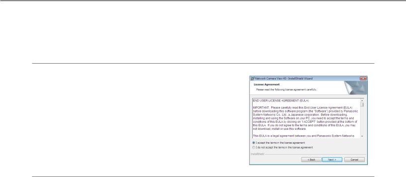
Viewer software
•It is necessary to install the viewer software "Network Camera View 4S" to display images on a PC. This software can be installed directly from the camera or by double clicking "nwcv4Ssetup.exe" on the CD-ROM provided, and then following the on-screen instructions.
Important:
•The default setting of "Automatic installation of Viewer software" is "On". Follow the instructions on page 63 when the message is displayed on the information bar of the browser.
•When the "Live" page is displayed for the first time, the install wizard of the ActiveX control required to display images from the camera will be displayed. Follow the instructions of the wizard.
•When the install wizard is displayed again even after completing the installation of the ActiveX, restart the PC.
•The viewer software used on each PC should be licensed individually. The number of installations of the viewer software from the camera can be checked on the [Upgrade] tab of the "Maintenance" page ( page 54). Refer to your dealer for the software licensing.
4

Monitor images on a PC
The following are descriptions of how to monitor images from the camera on a PC.
Monitor images from a single camera
Step 1
Start up the web browser.
Step 2
Enter the IP address designated using the Panasonic IP setup software in the address box of the browser.
Example when entering an IPv4 address: http://URL registered using IPv4 address http://192.168.0.10/
Example when entering an IPv6 address: http://URL registered using IPv6 address http://[2001:db8::10]/
<Example of IPv4 access>
Important:
•When the HTTP port number is changed from "80", enter "http://IP address of the camera + : (colon) + port number" in the address box of the browser.
Example: If the port number is set to "8080": http://192.168.0.11:8080
•When the PC is in a local network, configure the proxy server setting of the web browser (under
"Internet Options…" under "Tools" of the menu bar) to bypass the proxy server for the local address.
Step 3
Press the [Enter] key on the keyboard.
→The "Live" page will be displayed. Refer to page 7 for further information about the "Live" page.
<Example of IPv6 access>
When "On" is selected for "User auth.", the authentication window will be displayed before displaying live images for the user name and password entries. The default user name and password are as follows.
User name: admin Password: 12345
5

Important:
•To enhance the security, change the password for the user name "admin". It is recommended to change this password periodically.
•When displaying multiple H.264 images on a PC, images may not be displayed depending on the performance of the PC.
Note:
•The maximum number of concurrent access user is 14 including users who is receiving H.264 images and users who are receiving JPEG images. Depending on the set values for "Bandwidth control(bit rate)" and "Max bit rate (per client)*", the maximum concurrent access number may be less than 14 users. When 14 users are concurrently accessing, the access limit message will be displayed for users who subsequently attempt to access. When "Multicast" is selected for "Transmission type" of "H.264", only the first user who accessed to monitor H.264 images will be included in the maximum number.
•When "On" is selected for "H.264 transmission" ( page 20), H.264 images will be displayed. When "Off" is selected, a JPEG image will be displayed. It is possible to display a JPEG image even when "On" is selected for
"H.264 transmission". In this case, the refresh interval of JPEG images will be limited to 5 fps.
•The refresh interval may become longer depending on a network environment, PC performance, photographic subject, access traffic, etc.
<Refresh interval of JPEG images>
When "On" is selected for "H.264 transmission": Max. 5 fps When "Off" is selected for "H.264 transmission": Max. 30 fps
6
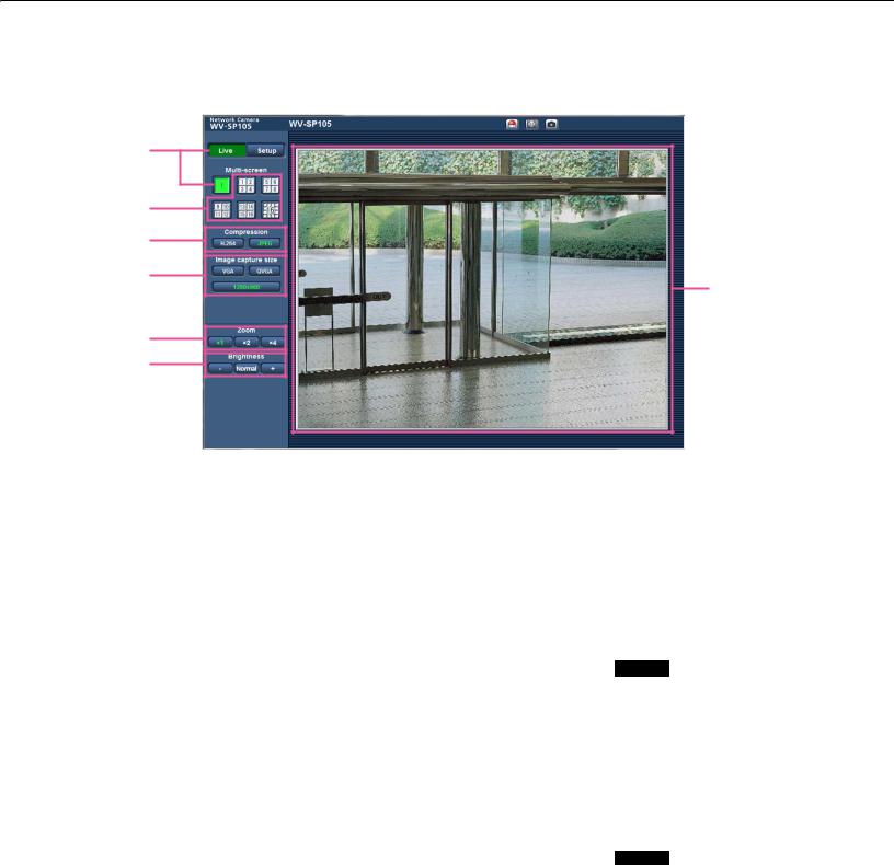
About the "Live" page
q |
|
i |
o !0!1 |
||||
|
|
|
|
|
|
|
|
|
|
|
|
|
|
|
|
|
|
|
|
|
|
|
|
w
e
r
t
!2
y u
q[Setup] button*1
Displays the setup menu. The button will turn green and the setup menu will be displayed.
w[Live] button
Display the "Live" page. The button will turn green and the "Live" page will be displayed.
e[Multi-screen] button
Images from multiple cameras can be displayed on a multi-screen by registering cameras on the setup menu. ( Page 9)
r[Compression] buttons
[H.264] button: The letters "H.264" on the button will turn green and H.264 image will be displayed. When "On" is selected for "H.264 transmission", the [H.264] button will be displayed. ( Page 20)
[JPEG] button: The letters "JPEG" on the button will turn green and JPEG image will be displayed.
t[Image capture size] buttons
These buttons will be displayed only when a JPEG image is displayed.
[VGA] button: The letters "VGA" will turn green and images in the main area will be displayed in VGA size.
[QVGA] button: The letters "QVGA" will turn green and images in the main area will be displayed in QVGA size.
[1280x960] button: SP105
The letters "1280x960" will turn green and images in the main area will be displayed in 1280 x 960 (pixels).
[640x360] button: The letters "640x360" will turn green and images in the main area will be displayed in 640 x 360 (pixels).
[320x180] button: The letters "320x180" will turn green and images in the main area will be displayed in 320 x 180 (pixels).
[1280x720] button: SP105
The letters "1280x720" will turn green and images in the main area will be displayed in 1280 x 720 (pixels).
7

Note:
•The buttons [VGA] and [QVGA] are displayed only when "4:3" is selected for "Aspect ratio".
•The buttons [640x360] and [320x180] are displayed only when "16:9" is selected for "Aspect ratio".
•When "1280x960" or "1280x720" is selected for the image capture size, it may become smaller than the actual size depending on the window size of the web browser.
y[Zoom] buttons
[x1] button: The letter "x1" will turn green and images in the main area will be displayed at x1.
[x2] button: The letter "x2" will turn green and images in the main area will be displayed at x2.
[x4] button: The letter "x4" will turn green and images in the main area will be displayed at x4.
u[Brightness] buttons*2
[–](darker) button: The displayed image will be darker.
[Normal] button: The adjusted brightness will return to the default brightness.
[+] (brighter) button: Image will be brighter.
i Camera title
The camera title entered for "Camera title" on the [Basic] tab will be displayed. ( Page 17)
oAlarm occurrence indication button*2
This button will be displayed and will blink when an alarm has occurred. When this button is clicked, the button will disappear. ( Page 10)
!0Full screen button
Images will be displayed on a full screen. (The aspect ratio of displayed images will be adjusted in accordance with the monitor.) To return to the "Live" page, press the [Esc] key.
!1One shot button
Click this button to take a picture (a still picture). The picture will be displayed on a newly opened window. When right-clicking on the displayed image, the pop-up menu will be displayed. It is possible to save the image on the PC by selecting "Save" from the displayed pop-up menu.
When "Print" is selected, printer output is enabled.
!2Main area
Images from the camera will be displayed in this area.
The current time and date will be displayed according to the settings configured for "Time display format" and "Date/time display format". ( Page 17)
When clicking a desired point while displaying live images at x2 or x4 in the main area, the camera will move to locate the clicked point at the center of the main area.
*1 Only operable by users whose access level is "1.
Administrator".
*2 Only operable by users whose access level is "1. Administrator" or "2. Camera control" when "On" is selected for "User auth." ( page 38).
Note:
•When operated by a lower access level user, images displayed on the screen may be changed temporarily. This does not affect operation of the camera.
•A zoom operation can be performed using the mouse wheel.
•Depending on the PC in use, the top and bottom of the images may be displayed out of alignment.
8
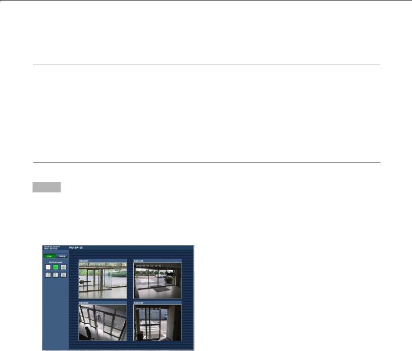
Monitor images from multiple cameras
Images from multiple cameras can be displayed on a multi-screen. Images from 4 cameras (up to 16 cameras) can be displayed simultaneously. To display images on a multi-screen, it is necessary to register cameras in advance. 4 cameras can be registered as a group and up to 4 groups (16 cameras) can be registered. ( Page 30)
Important:
•When displaying images on a 16-screen, panning, tilting and zooming operations become unavailable for images from the Panasonic PTZ cameras.
•When displaying images on a 4-screen, panning, tilting and zooming operations become available only for images from the Panasonic PTZ cameras. Refer to the "Readme" file on the provided CD-ROM for further information about the compatible PTZ cameras and their versions.
•Only JPEG images can be displayed on a multi-screen. Audio will not be heard.
•When the power is turned off or the LAN cable is disconnected while displaying images, displaying images on a multi-screen from the "Live" page will become unavailable.
•When displaying the image on a multi-screen and "16:9" is selected for "Aspect ratio", the image will be displayed altered vertically to the aspect ratio of "4:3".
Step 1
Click the desired [Multi-screen] button.
→Images from the registered cameras will be displayed on a selected multi-screen (screen can be split up to 16 areas). The following are instructions when displaying on a 4-split screen.
|
|
|
|
|
|
|
|
|
|
|
|
|
|
|
|
|
|
|
|
|
|
|
|
|
|
|
|
|
|
|
|
|
|
|
|
|
|
|
|
|
|
|
|
|
|
|
|
|
|
|
|
|
|
|
|
|
|
|
|
|
|
|
|
|
|
|
|
|
|
|
|
|
|
|
|
|
|
|
|
|
|
|
|
|
|
|
|
|
|
|
|
|
|
|
|
|
|
|
|
|
|
|
|
|
|
|
|
q |
|
|
|
|
|
|
|
|
w |
||
qTo display images on a single screen, click the [Live] button.
wClick a camera title. Live images from the camera corresponding to the clicked camera title will be displayed on the "Live" page of the newly opened window.
9

Action at an alarm occurrence
The alarm action (camera action at an alarm occurrence) will be performed when the following alarms occur.
Alarm type
VMD alarm: |
When motion is detected in the set VMD area, the alarm action will be performed. |
|
* VMD stands for "Video Motion Detection". |
Command alarm: |
When a Panasonic alarm protocol is received from the connected device via a network, the |
|
alarm action will be performed. |
Action at an alarm occurrence
Display the alarm occurrence indication button on the "Live" page. ( Page 8)
The alarm occurrence indication button will be displayed on the "Live" page at an alarm occurrence.
Important:
•When "Polling(30sec)" is selected for "Alarm status update mode" ( page 18), the alarm occurrence indication button will be refreshed in 30 second intervals. For this reason, it may take a maximum of 30 seconds until the alarm occurrence indication button is displayed on the "Live" page at an alarm occurrence.
Transmit an image onto a server automatically
An alarm image can be transmitted at an alarm occurrence to the server designated in advance. The settings required to transmit an alarm image to a server can be configured in the "Alarm image" section on the [Alarm] tab of the "Alarm" page ( page 32) and the [FTP] tab of the "Server" page ( page 41).
Notify of alarm occurrences by e-mail
Alarm mail (alarm occurrence notification) can be sent at an alarm occurrence to the e-mail addresses registered in advance. Up to 4 addresses can be registered as recipients of the alarm mail. An alarm image (still picture) can be sent with the alarm mail as an attached file. The settings for alarm mail can be configured in the "Mail notification" section on the [Notification] tab of the "Alarm" page ( page 36) and the [Mail] tab of the "Server" page ( page 41).
Notify of alarm occurrences to the designated IP addresses (Panasonic alarm protocol notification)
This function is available only when a Panasonic device, such as the network disk recorder, is connected to the system. When "On" is selected for "Panasonic alarm protocol notification", the connected Panasonic device will be notified that the camera is in the alarm state. The settings for Panasonic alarm protocol can be configured in the Panasonic alarm protocol section of the [Notification] tab of the "Alarm" page. ( Page 37)
10
Transmit images onto an FTP server
Images can be transmitted to an FTP server. By configuring the following settings, transmission of images captured at an alarm occurrence or captured at a designated interval to an FTP server will become available.
Important:
•When using this function, set the user name and the password to access the FTP server to restrict users who can log into the FTP server.
Transmit an alarm image at an alarm occurrence (Alarm image transmission)
An alarm image can be transmitted at an alarm occurrence to the FTP server. To transmit alarm images to an FTP server, it is necessary to configure the settings in advance.
The settings for the FTP server can be configured on the [FTP] tab of the "Server" page. ( Page 42)
The alarm image transmission function can be turned on/off in the "Alarm image" section of the [Alarm] tab of the "Alarm" page. ( Page 32)
Note:
•Depending on the network traffic, the number of the transmitted images may not reach the set number of images to be transmitted.
Transmit images at a designated interval or period (FTP periodic image transmission)
Images can be transmitted at a designated interval or period. To transmit images at a designated interval or period, it is necessary to configure the settings in advance.
The settings for the FTP server can be configured on the [FTP] tab of the "Server" page. ( Page 42)
It is possible to determine whether or not to use the FTP periodic image transmission function and to configure the settings relating to alarm images and the schedule on the "FTP img. trans." tab of the "Network" page.
( Page 50)
Note:
•Depending on the line speed or the traffic, images may not be transmitted at the designated interval.
•When "On" is selected for both the alarm image transmission function and the FTP periodic image transmission function, the alarm image transmission function will be given priority over the FTP periodic image transmission function. Therefore, images may not be transmitted at the interval designated on the "FTP periodic image transmission" setting.
11

About the network security
Equipped security functions
The following security functions are featured in this camera.
qAccess restrictions by the host authentication and the user authentication
It is possible to restrict users from accessing the camera by setting the host authentication and/or the user authentication to "On". ( Pages 38 and 39)
wAccess restrictions by changing the HTTP port
It is possible to prevent illegal access such as port scanning, etc. by changing the HTTP port number. ( Page 45)
Important:
•Design and enhance security countermeasures to prevent leakage of information such as image data, authentication information (user name and password), alarm mail information, FTP server information, DDNS server information, etc. Perform the countermeasure such as the access restriction using the user authentication.
•After the camera is accessed by the administrator, make sure to close the browser for added security.
•Change the administrator password periodically for added security.
Note:
•When user authentication (authentication error) has failed to pass 8 times within 30 seconds using the same IP address (PC), access to the camera will be denied for a while.
12

Display the setup menu from a PC
The settings of the camera can be configured on the setup menu.
Important:
•The setup menu is only operable by users whose access level is "1. Administrator". Refer to page 38 for how to configure the access level.
How to display the setup menu
Step 1
Display the "Live" page. ( Page 5)
Step 2
Click the [Setup] button on the "Live" page.
→The window with the user name and password entry fields will be displayed.
Step 3
Click the [OK] button after entering the user name and the password.
→The setup menu will be displayed. Refer to page 15 for further information about this menu.
13
How to operate the setup menu
Menu buttons |
Setup page |
Step 1
Click the desired button in the frame on the left of the window to display the respective setup menu.
When there are tabs at the top of the setup page displayed in the frame on the right of the window, click the desired tab to display and configure the setting items relating to the name of the tab.
Step 2
Complete each setting item displayed in the frame on the right of the window.
Step 3
After completing each setting item, click the [Set] button to apply them.
Important:
•When there are two or more [Set] and [Execute] buttons on the page, click the respective button to the edited setting item.
<Example>
A
A-1
B
B-1
When completing the setting items in field A, click the [Set] button (A-1) below field (A). The edited settings in field A will not be applied unless the [Set] button (A-1) below field (A) is clicked. In the same manner as above, click the [Set] button (B-1) below field B when completing the setting items in field B.
14
About the setup menu window |
|
|
|
|
|||||||||||||||||||||||
q [Setup] button |
|
|
|
|
!3 Camera title |
||||||||||||||||||||||
w [Live] button |
|
|
|
|
|
|
|
|
|
|
|
|
|
|
|
|
|
|
|
|
|
|
|
|
|
||
|
|
|
|
|
|
|
|
|
|
|
|
|
|
|
|
|
|
|
|
|
|
|
|
|
|||
|
|
|
|
|
|
|
|
|
|
|
|
|
|
|
|
|
|
|
|
|
|
|
|
|
|
|
|
|
|
|
|
|
|
|
|
|
|||||||||||||||||||
e [Basic] button |
|
|
|
|
|
|
|
|
|
|
|
|
|
|
|
|
|
|
|
|
|
|
|||||
|
|
|
|
|
|
|
|
|
|
|
|
|
|
|
|
|
|
|
|
||||||||
r [Image] button |
|
|
|
|
|
|
|
|
|
|
|
|
|
|
|
|
|
|
|
|
|
||||||
|
|
|
|
|
|
|
|
|
|
|
|
|
|
|
|
|
|
|
|||||||||
t [Multi-screen] button |
|
|
|
|
|
|
|
|
|
|
|
|
|
|
|
|
|
||||||||||
|
|
|
|
|
|
|
|
|
|
|
|
|
|
|
|||||||||||||
y [Alarm] button |
|
|
|
|
|
|
|
|
|
|
|
|
|
|
|
|
|
|
|
|
|
|
|
||||
|
|
|
|
|
|
|
|
|
|
|
|
|
|
|
|
|
|
|
|
|
|||||||
u [User mng.] button |
|
|
|
|
|
|
|
|
|
|
|
|
|
|
|
|
|
!4 Setup page |
|||||||||
|
|
|
|
|
|
|
|
|
|
|
|
|
|
|
|||||||||||||
|
|
|
|
|
|
|
|
|
|
|
|
|
|
|
|||||||||||||
i [Server] button |
|
|
|
|
|
|
|
|
|
|
|
|
|
|
|
|
|
|
|||||||||
|
|
|
|
|
|
|
|
|
|
|
|
|
|
|
|
|
|||||||||||
o [Network] button |
|
|
|
|
|
|
|
|
|
|
|
|
|
|
|
|
|
|
|
||||||||
|
|
|
|
|
|
|
|
|
|
|
|
|
|
|
|
|
|
|
|
||||||||
|
|
|
|
|
|
|
|
|
|
||||||||||||||||||
!0[Schedule] button |
|
|
|
|
|
|
|
|
|
|
|
|
|
|
|||||||||||||
|
|
|
|
|
|
|
|||||||||||||||||||||
!1 [Maintenance] button |
|
|
|
|
|
|
|
|
|
|
|
|
|||||||||||||||
|
|
|
|
|
|
||||||||||||||||||||||
!2 [Help] button |
|
|
|
|
|
|
|
|
|
||||||||||||||||||
|
|
|
|
|
|
||||||||||||||||||||||
|
|
|
|
|
|
|
|
|
|
|
|
|
|
|
|
|
|
|
|
|
|
|
|
|
|
|
|
q[Setup] button
Displays the setup menu.
w[Live] button
Display the "Live" page.
e[Basic] button
Displays the "Basic" page. The basic settings such as time and date and camera title can be configured on the "Basic" page. ( Page 17)
r[Image] button
Displays the "Image" page. The settings relating to image capture size and image quality of JPEG/H.264 camera images can be configured on the "Image" page. ( Page 19)
t[Multi-screen] button
Displays the "Multi-screen" page. The cameras from which images are to be displayed on a multi-screen can be registered on the "Multi-screen" page.
( Page 30)
y[Alarm] button
Displays the "Alarm" page. The settings relating to alarm occurrences such as settings for the alarm action at an alarm occurrence, the alarm occurrence notification, and the VMD area settings can be configured on the "Alarm" page. ( Page 31)
u[User mng.] button
Displays the "User mng." page. The settings relating to the authentication such as users and PCs restrictions for accessing the camera can be configured on the "User mng." page. ( Page 38)
i[Server] button
Displays the "Server" page. The settings relating to the mail server, the FTP server and the NTP server to which the camera accesses can be configured on the "Serve" page. ( Page 41)
o[Network] button
Displays the "Network" page. The network settings and the settings relating to DDNS (Dynamic DNS), SNMP (Simple Network Management Protocol) and the FTP (File Transfer Protocol) periodic transmission can be configured on the "Network" page.
( Page 44)
15

!0[Schedule] button
Displays the "Schedule" page. On the "Schedule" page, it is possible to designate time zones to allow to activate the VMD detection function or allow to access the cameras. ( Page 52)
!1[Maintenance] button
Displays the "Maintenance" page. System log check, firmware upgrade and initialization of the setup menu can be carried out on the "Maintenance" page. ( Page 53)
!2[Help] button
Displays the "Help" page. ( Page 56)
!3Camera title
The title of the camera whose settings are currently being configured will be displayed.
!4Setup page
Pages of each setup menu will be displayed. There are tabs for some setup menus. When the underlined item is clicked, the corresponding help page will be displayed.
16
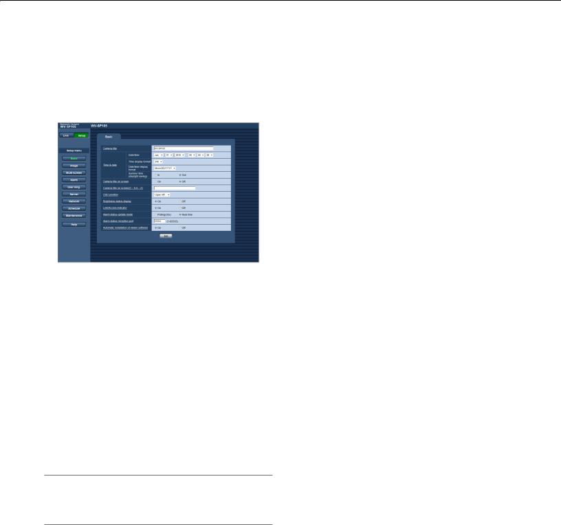
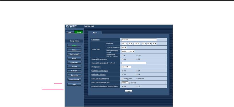
Configure the basic settings of the camera [Basic]
The basic settings such as camera title and time and date can be configured on the "Basic" page.
Configure the basic settings [Basic]
Click the [Basic] tab on the "Basic" page. ( Pages 13 and 14: How to display/operate the setup menu)
The settings such as the camera title, time and date, etc. can be configured on this page.
[Camera title]
Enter the title of the camera. Click the [Set] button after entering the title of the camera. The entered title will be displayed in the camera title field.
Available number of characters: 0 - 20 characters
Default: Varies as follows depending on the model in use.
WV-SP105
WV-SP102
[Date/time]
Enter the current time and date. When "12h" is selected for "Time display format", "AM" or "PM" can be selected.
Available range: 01/01/2010 00:00:00 - 31/12/2035 23:59:59
Important:
•Use an NTP server when the more accurate time & date setting is required for the system operation. Page 43)
[Time display format]
Select the time display format from "24h", "12h" and
"Off". Enter the current hour reflecting this setting when entering the current time and date for "Date/time". To hide time and date, select "Off".
Default: 24h
[Date/time display format]
Select a date/time display format. When "2010/04/01
13:10:00" is set for "Date/time" after selecting "24h" for "Date/time display format", time & date will be respectively displayed as follows.
DD/MM/YYYY: 01/04/2010 13:10:00
MM/DD/YYYY: 04/01/2010 13:10:00 DD/Mmm/YYYY: 01/Apr/2010 13:10:00 YYYY/MM/DD: 2010/04/01 13:10:00 Mmm/DD/YYYY: Apr/01/2010 13:10:00
Default: DD/MM/YYYY (PAL model) Mmm/DD/YYYY (NTSC model)
[Summer time(daylight saving)]
Select "In" or "Out" to determine whether or not to apply daylight saving time. Configure this setting if the summer time (daylight saving time) is applied in the location where the camera is in use.
In: Applies summer time. An asterisk (*) will be displayed on the left side of the displayed time and date.
Out: Does not apply summer time.
Default: Out
[Camera title on screen]
Select "On" or "Off" to determine whether or not to display the camera title on the screen.
When "On" is selected, the character string entered for
"Camera title on screen(0 - 9,A - Z)" will be displayed at the position selected for "OSD position".
Default: Off
[Camera title on screen(0 - 9,A - Z)]
Enter a character string to be displayed on the image.
Available number of characters: 0 - 16 characters
Available characters: 0-9, A-Z and the following marks.
!"#$% &'()*+,-./:; =?
Default: None (blank)
17

[OSD position]
Select the position where the time and date and a character string to be displayed on the image of the "Live" page.
Upper left: The above information will be displayed at the upper left corner of the main area on the "Live" page.
Lower left: The above information will be displayed at the lower left corner of the main area on the "Live" page.
Upper right: The above information will be displayed at the upper right corner of the main area on the "Live" page.
Lower right: The above information will be displayed at the lower right corner of the main area on the "Live" page.
Default: Upper left
[Brightness status display]
Select "On" or "Off" to determine whether or not to display the status of brightness on images displayed on the "Live" page when adjusting brightness.
Default: On
[Link/Access indicator]
Determine whether or not to use the following indicators. Select "On" to use the following indicators to check the operational status by lighting them.
Select "Off" to turn off the indicators at all times.
•Power indicator
•Link indicator
•Access indicator
Default: On
Note:
•Power indicator (green):
This indicator will light when the power is on.
•Link indicator (orange):
This indicator will light when communication with the connected device is available.
•Access indicator (Green):
This indicator will light when accessing a network.
[Alarm status update mode]
Select an interval of the camera status notification from the following.
When the status of the camera changes, the alarm occurrence indication button will be displayed to notify of the camera status.
Polling(30sec): Updates the status each 30 seconds and provide notification of the camera status.
Real time: Provide notification of the camera status when the status has changed.
Default: Real time
Note:
•Depending on the network environment, notification may not be provided in real time.
[Alarm status reception port]
When selecting "Real time" for "Alarm status update mode", designate a port number to which the status change notification is to be sent.
Refer to the help window to infomation about the unavailable port number.
Available port number: 1 - 65535 Default: 31004
[Automatic installation of viewer software]
Determine whether or not to install the viewer software from this camera.
On: Installs the viewer software from the camera automatically.
Off: The viewer software cannot be installed from the camera.
Default: On
Important:
•It is impossible to display images when the viewer software "Network Camera View 4S" is not installed on the PC.
•The number of the viewer software installations can be checked on the [Upgrade] tab of the "Maintenance" page.
18

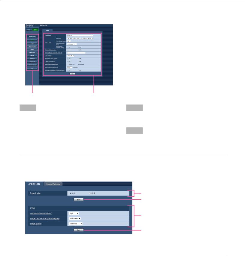
Configure the settings relating to images [Image]
The settings relating to JPEG and H.264 images such as the settings of image quality, etc. can be configured on this page.
The "Image" page has 2 tabs; the [JPEG/H.264] tab and the [Image/Privacy] tab.
Configure the settings relating to the aspect ratio [JPEG/H.264]
Click the [JPEG/H.24] tab on the "Image" page. ( Pages 13 and 14: How to display/operate the setup menu)
[Aspect ratio]
Select "4:3" or "16:9" for the aspect ratio.
Default: 4:3
Note:
•i-PRO Series does not support aspect ratio of "16:9", if not specified (as of October 2010).
•Image adjustment functions are activated for the angle of view in the aspect ratio of 4:3 even while "16:9" is being selected for "Aspect ratio". Area masking under the backlight compensation (BLC) function can be set only when the aspect ratio is
"4:3".
If the aspect ratio is changed to "16:9" after setting of the backlight compensation function, the setting of area masking is maintained.
Configure the settings relating to JPEG images [JPEG/H.264]
Click the [JPEG/H.24] tab on the "Image" page. ( Pages 13 and 14: How to display/operate the setup menu)
■ JPEG
Configure the settings such as "Refresh interval (JPEG)*", "Image capture size" and "Image quality" on this section. Refer to page 20 for further information about the settings relating to H.264 images.
[Refresh interval (JPEG)*]
Select an interval to refresh the displayed JPEG image from the following.
0.1fps/ 0.2fps/ 0.33fps/ 0.5fps/ 1fps/ 2fps/ 3fps/ 5fps/ 6fps*/ 10fps*/ 12fps* (PAL model)/ 15fps*/ 30fps*
Default: 5fps
Note:
•When "On" is selected for "H.264 transmission", the refresh interval may be longer than the set value when any value with an asterisk (*) on the right is selected.
[Image capture size (Initial display)]
Select the image capture size to display the JPEG image on the "Live" page for the first time.
•When "4:3" is selected for "Aspect ratio"
QVGA/ VGA/ 1280 x 960*1
•When "16:9" is selected for "Aspect ratio"
320×180/ 640×360/ 1280 ×720*1
Default: 1280x960*1
VGA*2
*1 SP105
*2 SP102
19
[Image quality]
Specify the image quality of JPEG images.
0 Super fine/ 1 Fine/ 2/ 3/ 4/ 5 Normal/ 6/ 7/ 8/ 9 Low
Default: 5 Normal
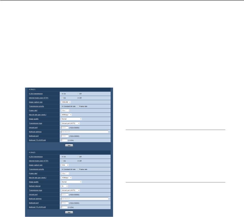
Configure the settings relating to H.264 images [JPEG/H.264]
Click the [JPEG/H.24] tab on the "Image" page. ( Pages 13 and 14: How to display/operate the setup menu)
Configure the settings relating to H.264 image such as "Max bit rate (per client)*", "Image capture size", "Image quality", etc. in this section.
Refer to page 19 for further information about the settings relating to JPEG images.
■ H.264 (1) · H.264 (2)
[H.264 transmission]
Select "On" or "Off" to determine whether or not to transmit H.264 images.
On: Transmits H.264 images.
Off: Does not transmit H.264 images.
Default: On
Note:
• When "On" is selected for "H.264 transmission" in
"H.264(1)", displaying of H.264 images or JPEG images on the "Live" page will be available.
• When "On" is selected for "H.264 transmission" in
"H.264(1)" and "H.264(2)", H.264 images are viewable using other devices with each setting.
• When "On" is selected for "H.264 transmission" in
"H.264(1)" or "H.264(2)", the transmission interval of JPEG images may sometimes become longer.
[Internet mode (over HTTP)]
Select "On" when transmitting H.264 images via the
Internet. It is possible to transmit H.264 images without changing the broadband router settings configured for JPEG image transmission.
On: H.264 images will be transmitted using the HTTP port. Refer to page 45 for further information about the HTTP port number settings.
Off: H.264 images will be transmitted using the UDP port.
Default: Off
20
 Loading...