


 Loading...
Operating Instructions
Network Camera
Model No. WV-X6500 Series
WV-S6500 Series
WV-S6100 Series
WV-X6531N
LOCK |
OPEN |
|
 -S6130
WV
WV-S6130
WV-S6131
This manual covers the models: WV-X6500 Series (WV-X6531N, WV-X6531NS, WV-X6511N), WV-S6500 Series (WV-S6530N), WV-S6100 Series (WV-S6131, WV-S6111, WV-S6130).
Before attempting to connect or operate this product, please read these instructions carefully and save this manual for future use.
The model number is abbreviated in some descriptions in this manual.

Preface
Preface
About the user manuals
There are 3 sets of operating instructions as follows.
•Operating Instructions (this document): Explains how to perform the settings and how to operate this camera.
•Important Information: Provides information about the cautions required for safely using and installing this camera.
•Installation Guide: Explains how to install and connect devices.
The screens used in these operating instructions show the case of WV-X6531N. Depending on the model used, the screens shown in the explanations may differ to the actual camera screens.
About notations
The following notations are used when describing the functions limited for specified models. The functions without the notations are supported by all models.
X6531 : The functions with this notation are available when using the model WV-X6531N, WV-X6531NS. X6511 : The functions with this notation are available when using the model WV-X6511N.
S6131 : The functions with this notation are available when using the model WV-S6131. S6111 : The functions with this notation are available when using the model WV-S6111. S6130 : The functions with this notation are available when using the model WV-S6130.
S6530 : The functions with this notation are available when using the model WV-S6530N.
Abbreviations
The following abbreviations are used in these operating instructions. Microsoft Windows 10 is described as Windows 10.
Microsoft Windows 8.1 is described as Windows 8.1. Microsoft Windows 8 is described as Windows 8. Microsoft Windows 7 is described as Windows 7.
Windows Internet Explorer 11, Windows Internet Explorer 10, Windows Internet Explorer 9 and Windows Internet Explorer 8 are described as Internet Explorer.
SDXC/SDHC/SD memory card is described as SD card or SD memory card. Universal Plug and Play is described as UPnP™ or UPnP.
2Operating Instructions
Preface
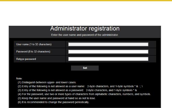
For administrator registration
At the time of first access to the camera (or at the time of initialization), the registration screen will be displayed.
[User name (1 to 32 characters)]
Enter the user name of the administrator.
Available number of characters: 1 - 32 characters
Unavailable characters: 2-byte characters, and 1-byte symbols " & : ; \
[Password (8 to 32 characters)]/[Retype password]
Enter the administrator password.
Available number of characters: 8 - 32 characters
Unavailable characters: 2-byte characters, and 1-byte symbols " &
Note
•Distinguish between upperand lower cases.
•For the password, use two or more types of characters from alphabetic characters, numbers, and symbols.
IMPORTANT
•If you forgot or do not know the password or user name, the camera must be initialized. Because all settings other than preset position settings are deleted when the camera is initialized, make sure to keep the information secure from third parties. Refer to “Parts and functions” section in the Important Information in the supplied CD-ROM for more information about initializing the camera.
•It is recommended to change the password periodically.
The registration completion screen will be displayed after registering a user name and password of the administrator. After 10 seconds, the camera will be reconnected automatically. Please click “here” if it is not displayed automatically.
Operating Instructions |
3 |
|
|

Preface
When the camera is reconnected to, an authentication window is displayed. Enter the registered user name and password to start operation.
Viewer software
In order to display H.265 (or H.264) images, send/receive audio to/from the camera, and play images saved on the SD memory card, the “Network Camera View 4S” (ActiveX) viewer software must be installed. This software can be installed directly from the camera or by selecting the [Install] button next to [Viewer Software] on the menu of the CD-ROM provided, and then following the on-screen instructions.
IMPORTANT
•The default setting of “Automatic installation” is “On”. Follow the instructions on page 268 when the message is displayed on the information bar of the browser.
•Depending on the software environment of your PC, it may take time for the message to be displayed on the information bar of the browser.
•If you display the “Live” page on a PC and click the [Viewer Software] button, the installation screen for ActiveX, which is required for viewing camera images, is displayed. Follow the on-screen instructions and install the software. When displayed JPEG images (still images), there is no need to install ActiveX.
4Operating Instructions

Preface
•When the install wizard is displayed again even after completing the installation of the ActiveX, restart the PC.
•The viewer software used on each PC should be licensed individually. The number of installations of the viewer software from the camera can be checked on the [Upgrade] tab of the “Maintenance” page (®page 239). Refer to your dealer for the software licensing.
Operating Instructions |
5 |
|
|

Table of Contents |
|
|
Table of Contents |
|
|
1 Operations ................................................................................................ |
9 |
|
1.1 |
Monitor images on a PC ................................................................................................... |
9 |
1.1.1 |
Monitor images from a single camera .............................................................................. |
9 |
1.1.2 |
About the “Live” page ..................................................................................................... |
12 |
1.1.3 |
Monitor images from multiple cameras .......................................................................... |
18 |
1.2 |
Monitor images on a cellular phone/mobile terminal .................................................. |
21 |
1.2.1 |
Monitor images on a cellular phone ............................................................................... |
21 |
1.2.2 |
Monitor images on a mobile terminal (including smartphones) ...................................... |
23 |
1.3 |
Record images on the SD memory card manually ...................................................... |
30 |
1.4 |
Action at an alarm occurrence ....................................................................................... |
32 |
1.4.1 |
Alarm type ...................................................................................................................... |
32 |
1.4.2 |
Action at an alarm occurrence ........................................................................................ |
32 |
1.5 |
Transmit images onto an FTP server ............................................................................ |
34 |
1.5.1 |
Transmit an alarm image at an alarm occurrence (Alarm image transmission) ............. |
34 |
1.5.2Transmit images at a designated interval or period (FTP periodic image
transmission) |
..................................................................................................................34 |
1.5.3Save images on the SD memory card when images fail to transmit using the FTP periodic
|
image transmission function ........................................................................................... |
35 |
1.6 |
Display the log list .......................................................................................................... |
36 |
1.7 |
Playback of images on the SD memory card ............................................................... |
40 |
1.7.1Playback “JPEG(1)”/“JPEG(2)”/“JPEG(3)” images saved to the SD memory
card |
................................................................................................................................40 |
1.7.2Playback “Stream(1)”/“Stream(2)”/“Stream(3)”/“Stream(4)” images saved to the SD
|
memory card .................................................................................................................. |
43 |
2 Settings ................................................................................................... |
46 |
|
2.1 |
About the network security ............................................................................................ |
46 |
2.1.1 |
Equipped security functions ........................................................................................... |
46 |
2.2 |
Display the setup menu from a PC ................................................................................ |
47 |
2.2.1 |
How to display the setup menu ...................................................................................... |
47 |
2.2.2 |
How to operate the setup menu ..................................................................................... |
48 |
2.2.3 |
About the setup menu window ....................................................................................... |
49 |
2.3 |
Use Easy Setup [Easy Setup] ........................................................................................ |
51 |
2.3.1 |
Configure the Internet settings [Internet] ........................................................................ |
51 |
2.3.2 |
Configure an event action [Event action] ........................................................................ |
52 |
2.3.2.1 |
Configure the schedule/alarm (event function type setup menu) ................................ |
55 |
2.3.2.2 |
Alarm: Configure the terminal and VMD (alarm setup menu) ...................................... |
56 |
2.3.2.3 |
Alarm: Configure the alarm function type (Alarm function type setup menu) .............. |
59 |
2.3.2.4 |
Alarm: Configure the details for image transfer or recording conditions ...................... |
60 |
2.3.2.5 |
Alarm: Configure the output terminal ........................................................................... |
62 |
2.3.2.6 |
Alarm: configure the mail notifications and mail server ............................................... |
63 |
2.3.2.7Schedule: Configure SD recording or FTP periodic image transmission (schedule
|
function type setup menu) ........................................................................................... |
65 |
2.3.2.8 |
Schedule: Set SD memory recording (video recording setup menu) .......................... |
65 |
2.3.2.9Schedule: Configure FTP periodic image transmission (FTP periodic image transmission
|
setup menu) ................................................................................................................. |
67 |
2.4 |
Configure the basic settings of the camera [Basic] .................................................... |
71 |
2.4.1 |
Configure the basic settings [Basic] ............................................................................... |
71 |
2.4.2 |
Configure the settings relating to the SD memory card [SD memory card] .................... |
78 |
2.4.3 |
Configure the settings relating to alteration detection [Alteration detection] .................. |
85 |
2.4.4 |
How to configure alteration detection settings ................................................................ |
86 |
2.4.4.1 |
Generation of the CRT key (encryption key) ............................................................... |
87 |
6Operating Instructions

|
|
Table of Contents |
2.4.4.2 |
Generation of CSR (Certificate Signing Request) |
.......................................................88 |
2.4.4.3 |
Installation of the certificate issued by CA ................................................................... |
89 |
2.4.4.4 |
Configuration of alteration detection ............................................................................ |
90 |
2.4.5Access copy images saved on the SD memory card onto the PC [SD memory card
|
images] ........................................................................................................................... |
91 |
2.4.6 |
Configure the directory of the PC that images will be downloaded to [Log] ................... |
93 |
2.5 |
Configure the settings relating to images and audio [Image/Audio] ......................... |
95 |
2.5.1 |
Configure the settings relating to the image capture mode [Image] ............................... |
95 |
2.5.2 |
Configure the settings relating to JPEG images [Image] ................................................ |
96 |
2.5.3 |
Configure the settings relating to Stream [Image] .......................................................... |
98 |
2.5.4 |
Configure the settings relating to the camera operations [Cam. Function] .................. |
105 |
2.5.5Configure the settings relating to images and the preset positions [Image/
|
Position] ........................................................................................................................ |
110 |
2.5.5.1 |
Configure the settings relating to image quality (“Image adjust” setup menu) .......... |
111 |
2.5.5.2 |
Set mask areas .......................................................................................................... |
121 |
2.5.5.3Configure the settings relating to the preset positions (“Preset position” setup
menu) |
........................................................................................................................123 |
2.5.5.4Configure the settings relating to the auto pan function (“Auto pan” setup
|
menu) ........................................................................................................................ |
127 |
2.5.5.5 |
Configure the settings relating to patrol (“Patrol” setup menu) .................................. |
129 |
2.5.5.6 |
Configure the settings relating to auto track (“Auto track” setup menu) .................... |
131 |
2.5.5.7Configure the settings relating to direction/angle setting (“Direction/Angle setting” setup
menu) |
|
|
|
|
................................................................137 |
|
X6531 |
X6511 |
S6131 |
S6111 |
|
2.5.5.8Configure the settings relating to the privacy zone (“Privacy zone” setup
|
menu) ........................................................................................................................ |
138 |
2.5.5.9 |
Configure the VIQS setting ........................................................................................ |
141 |
2.5.5.10 |
Configure the VIQS area ........................................................................................... |
144 |
2.5.6 |
Configure the settings relating to audio [Audio] ............................................................ |
146 |
2.6 |
Configure the multi-screen settings [Multi-screen] ................................................... |
150 |
2.7 |
Configure the alarm settings [Alarm] .......................................................................... |
152 |
2.7.1 |
Configure the settings relating to the alarm action [Alarm] ........................................... |
152 |
2.7.2 |
Configure the settings relating to the output terminal [Alarm] ...................................... |
154 |
2.7.3 |
Change the AUX name [Alarm] .................................................................................... |
155 |
2.7.4Configure the settings relating to the camera action on alarm occurrence
[Alarm] |
..........................................................................................................................156 |
2.7.4.1Configure the settings relating to Preset per sender (“Preset per sender” setup
|
menu) ........................................................................................................................ |
159 |
2.7.4.2 |
Configure settings relating to image quality on alarm action ..................................... |
159 |
2.7.4.3 |
Configure settings relating to alarm E-mail notifications ............................................ |
161 |
2.7.4.4 |
Configure settings relating to FTP transmissions of alarm images ........................... |
162 |
2.7.4.5Configure settings relating to recording to an SD memory card when an alarm
occurs |
........................................................................................................................163 |
2.7.4.6Configure settings relating to Panasonic alarm protocol notification when an alarm
|
occurs ........................................................................................................................ |
164 |
2.7.4.7 |
Configure settings relating to HTTP alarm notification when an alarm occurs .......... |
165 |
2.7.5 |
Configure the VMD settings [VMD area] ...................................................................... |
165 |
2.7.6 |
Set the VMD areas [VMD area] .................................................................................... |
168 |
2.7.7 |
Configure the settings relating to the audio detection [Audio detection] ...................... |
170 |
2.7.8 |
Configuration of the settings relating to alarm notification [Notification] ....................... |
172 |
2.7.8.1 |
Configure the settings relating to Panasonic alarm protocol ..................................... |
173 |
2.7.8.2 |
Configure the settings relating to HTTP alarm notification ........................................ |
175 |
2.8 |
Configure the settings relating to the authentication [User mng.] ........................... |
177 |
2.8.1 |
Configure the settings relating to the user authentication [User auth.] ......................... |
177 |
2.8.2 |
Configure the settings relating to the host authentication [Host auth.] ......................... |
180 |
Operating Instructions |
7 |
|
|

Table of Contents
2.8.3 |
Configure IEEE 802.1X [IEEE 802.1X] ......................................................................... |
182 |
2.8.4 |
Configure the data encryption settings [Data encryption] ............................................. |
182 |
2.9 |
Configuring the network settings [Network] .............................................................. |
185 |
2.9.1 |
Configure the network settings [Network] ..................................................................... |
185 |
2.9.2 |
Configure advanced network settings [Advanced] ....................................................... |
190 |
2.9.2.1 |
Configure the settings related to sending E-mails ..................................................... |
191 |
2.9.2.2 |
Configure the settings related to FTP transmission ................................................... |
196 |
2.9.2.3 |
Configure the settings relating to the NTP server ...................................................... |
200 |
2.9.2.4 |
Configure the UPnP settings ..................................................................................... |
201 |
2.9.2.5 |
Configure the HTTPS settings ................................................................................... |
203 |
2.9.2.6 |
Configure the settings relating to DDNS .................................................................... |
204 |
2.9.2.7 |
Configure the settings relating to SNMP ................................................................... |
206 |
2.9.2.8 |
Configure the QoS settings ....................................................................................... |
207 |
2.9.3 |
How to configure HTTPS settings ................................................................................ |
209 |
2.9.3.1 |
Select the certificate to use when accessing with HTTPS ......................................... |
210 |
2.9.3.2 |
Obtaining the root certificate ...................................................................................... |
210 |
2.9.3.3 |
Configuration of HTTPS connections ........................................................................ |
216 |
2.9.3.4 |
Generation of the CRT key (SSL encryption key) ..................................................... |
217 |
2.9.3.5 |
Generation of CSR (Certificate Signing Request) ..................................................... |
218 |
2.9.3.6 |
Installation of the CA certificate ................................................................................. |
219 |
2.9.4 |
Access the camera using the HTTPS protocol (for pre-installed certificate) ................ |
220 |
2.9.4.1 |
Configuration of the host file ...................................................................................... |
220 |
2.9.5 |
Access the camera using the HTTPS protocol (for CA Certification) ........................... |
225 |
2.9.6 |
How to configure the settings relating to DDNS ........................................................... |
226 |
2.9.6.1Configuration of the DDNS service (Example of the “Viewnetcam.com”
|
service) ...................................................................................................................... |
227 |
2.9.6.2 |
When using “Dynamic DNS Update” ......................................................................... |
230 |
2.9.6.3 |
When using “Dynamic DNS Update(DHCP)” ............................................................ |
231 |
2.10 |
Configure the settings relating to the schedules [Schedule] ................................... |
232 |
2.10.1 |
How to set the schedules ............................................................................................. |
235 |
2.10.2 |
How to delete the set schedule .................................................................................... |
237 |
2.11 |
Maintenance of the camera [Maintenance] ................................................................. |
239 |
2.11.1 |
Check the system log [System log] .............................................................................. |
239 |
2.11.2 |
Upgrade the firmware [Upgrade] .................................................................................. |
239 |
2.11.3 |
Check the status [Status] ............................................................................................. |
241 |
2.11.4 |
Reset the settings/Reboot the camera [Default reset] .................................................. |
244 |
2.11.5 |
Settings data/backing up or restoring logs [Data] ......................................................... |
245 |
3 Others .................................................................................................... |
248 |
|
3.1 |
Using the CD-ROM ........................................................................................................ |
248 |
3.1.1 |
About the CD launcher ................................................................................................. |
248 |
3.1.2 |
Installing Panasonic “IP Setting Software” ................................................................... |
249 |
3.1.3 |
Installing the manuals ................................................................................................... |
250 |
3.1.4 |
Installing the Viewer software ....................................................................................... |
250 |
3.1.5Configure the network settings of the camera using the Panasonic “IP Setting
|
Software” ...................................................................................................................... |
251 |
3.2 |
About the displayed system log .................................................................................. |
254 |
3.3 |
Troubleshooting ............................................................................................................ |
259 |
3.4 |
Directory structure of drive B ...................................................................................... |
270 |
8Operating Instructions

1 Operations
1 Operations
1.1 Monitor images on a PC
The following are descriptions of how to monitor images from the camera on a PC.
1.1.1 Monitor images from a single camera
1.Start up the web browser.
2.Enter the IP address designated using the Panasonic “IP Setting Software” in the address box of the browser.
•Example when entering an IPv4 address: http://URL registered using IPv4 address http://192.168.0.10/
•Example when entering an IPv6 address: http://[URL registered using IPv6 address] http://[2001:db8::10]/
<Example of IPv4 access>
<Example of IPv6 access>
IMPORTANT
•When the HTTP port number is changed from “80”, enter “http://IP address of the camera + : (colon) + port number” in the address box of the browser. (Example: http://192.168.0.11:8080)
•When the PC is in a local network, configure the proxy server setting of the web browser (under [Internet Options...] under [Tools] of the menu bar) to bypass the proxy server for the local address.
Note
•Refer to page 220 and page 225 for further information about the case in which “HTTPS” is selected for “HTTPS” - “Connection” on the [Advanced] tab of the “Network” page (®page 185).
Operating Instructions |
9 |
|
|
1Operations
3.Press the [Enter] key on the keyboard.
→ The “Live” page will be displayed. Refer to page 12 for further information about the “Live” page.
When “On” is selected for “User auth.”, the authentication window will be displayed before displaying live images for the user name and password entries.
IMPORTANT
•It is recommended to change the password periodically.
•When displaying multiple H.265 (or H.264) images on a PC, images may not be displayed depending on the performance of the PC.
Note
•The maximum number of concurrent access user is 14 including users who is receiving H.265 (or H.
264)images and users who are receiving JPEG images. Depending on the set values for “Bandwidth control(bit rate)” and “Max bit rate (per client)*”, the maximum concurrent access number may be 14 or less users. When 14 users are concurrently accessing, the access limit message will be displayed for users who subsequently attempt to access. When “Multicast” is selected for “Transmission type” of “Stream”, only the first user who accessed to monitor H.265 (or H.264) images will be included in the maximum number. The second and subsequent users who are monitoring H.265 (or H.264) images will not be included in the maximum number.
•If you set the “Stream transmission” (®page 98) to “On”, an H.265 (or H.264) image will be displayed based on the settings of the “Stream encoding format”. If you set the “Stream transmission” (®page
98)to “Off”, a JPEG image will be displayed. A JPEG image can be displayed even if the “Stream transmission” is set to “On”, but in that case, the transmission interval of the JPEG image will be limited to maximum 5 fps.
•The refresh interval may become longer depending on a network environment, PC performance, photographic subject, access traffic, etc.
<Refresh interval of JPEG images>
When “On” is selected for “Stream transmission” max. 5fps
When “Off” is selected for “Stream transmission”
10 Operating Instructions
1 Operations
max. 30fps
Operating Instructions |
11 |
|
|
1 Operations
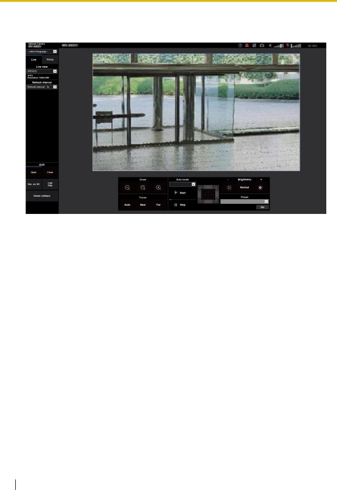
1.1.2 About the “Live” page
Note
•The buttons and setting items displayed on the “Live” page can be changed depending on the user rights of the accessing user. You can set the user right settings from “User auth.” under “User mng.”. (®page 177)
Q RS T U V W X
A
C
D
E
F
Y
G |
|
|
|
H |
|
|
O |
I |
|
|
|
J |
|
|
P |
|
|
|
|
K |
L |
M |
N |
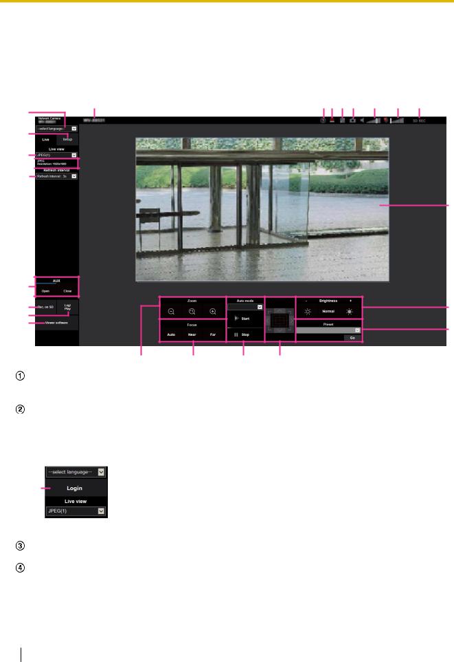
[select language] pull-down-menu
The camera’s display language can be selected. The default language can be set in the [Menu language] in the [Basic] settings. (®page 71)
[Login] button
This button is displayed when “User auth.” is “On” and a person other than the administrator logs in, or when “User auth.” is “Off” and “Guest User” is set to “Use”. (®page 177)
Even in the above case, the [Login] button will not be displayed if “Host auth.” is set to “On”, and the camera browser is opened from a host with administrator rights.
B
If login fails, close all the browsers, open the “Live” page and login once again.
[Setup] button*1
Displays the setup menu.
[Live view] pull-down menu
You can select and switch to the image to be displayed in the main area from the following: Stream(1)/Stream(2)/Stream(3)/Stream(4)/JPEG(1)/JPEG(2)/JPEG(3)/Multi-screen
The image in the main area is displayed based on the contents set in Stream(1) – (4) (®page 98), JPEG(1) – (3) (®page 96), or Multi-screen (®page 150).
12 Operating Instructions

1 Operations
Also the first stream displayed when you accessed the camera can be set from “Initial display stream” of the [Image] tab. For “Multi-screen”, you can set the “Initial display” in the [Multi-screen] tab.
Note
•When “2048´1536”, “1920´1080”, “1280´960” or “1280´720” is selected for the image capture size, it may become smaller than the actual size depending on the window size of the web browser.
Stream information display
Displays the setup for stream encoding format, image capture size, bit rate, and frame rate for the live view of a stream.
Note
•Displays the values set in the stream. The actual bit rate and frame rate vary depending on the network environment and the used PC.
[Refresh interval] pull-down menu
This pull-down menu will be displayed only when a JPEG image is displayed. Use it to select the display method of the JPEG image.
•MJPEG: Uses viewer software to display JPEG images successively as MJPEG (Motion JPEG). Not available if the viewer software is not installed.
•Refresh interval : 1s/Refresh interval : 3s/Refresh interval : 5s/Refresh interval : 10s/Refresh interval : 30s/Refresh interval : 60s: Refreshes JPEG format (still images) images at the specified interval.
Note
•Depending on the network environment or the PC used, JPEG format (still images) images may not be refreshed at the specified interval.
[AUX] button*2
These buttons will be displayed only when “Terminal 3” of “Alarm” is set to “AUX output” on the setup menu. (®page 56)
•[Open] button: The status of the AUX connector will be open.
•[Close] button: The status of the AUX connector will be closed.
Note
•The names of “AUX”, “Open” and “Close” can be changed. (®page 155)
[Rec. on SD] button*2
The [Rec. on SD] button will be displayed only when “Manual” is selected for “Save trigger” on the [SD memory card] tab. (®page 81)
Click this button to manually record images on the SD memory card. Refer to page 30 for descriptions of how to manually record images on the SD memory card.
[Log] button*2
When the [Log] button is clicked, the log list will be displayed and images saved on the SD memory card can be played.
Refer to page 36 for further information about the log list and for how to play images on the SD memory card.
[Viewer Software] button
Starts installation of the viewer software for display. This button will not be available if the viewer software is already installed on the PC, or if the “Automatic installation” of the [Viewer software (nwcv4Ssetup.exe)] in the [Basic] tab is set to “Off”. (®page 76)
[Zoom] button*2
• |
: Click this button to adjust the zoom ratio to the “Wide” side. |
• |
: Click this button to set the zoom ratio to x1.0. |
• |
: Click this button to adjust the zoom ratio to the “Tele” side. |
Operating Instructions |
13 |
|
|

1 Operations
[Focus] button*2
• : Click this button to adjust the focus automatically.
• : Click this button to adjust the focus to the “Near” side.
• : Click this button to adjust the focus to the “Far” side.
Note
•When shooting the following place or the following subjects, focus may not be adjustedautomatically. Adjust the focus manually.
–Shiny or strongly reflective subject
–Subject through the glass with dew or smudge
–Two subjects whose distances from the camera are different
–Less contrast subject (e.g. white wall)
–Horizontal-striped subject such as a window blind
–Inclined subject
–Dark subjects
Auto mode*2
Select an operation from the pull-down menu and click the [Start] button. The selected operation will start. Click the [Stop] button to stop the operation. The selected operation will stop when the camera (panning/ tilting/ zooming/ focusing) is operated or when an action to be taken according to the settings for “Self return” (®Page 105) or for “Camera action on alarm” (®Page 156) starts.
Note
•Operating in the auto mode for a long period of time wears the driving parts, and the replacement interval of those parts may be shortened. Refer to the Important Information in the supplied CD-ROM for the consumable parts.
•Auto track: Automatically tracks objects in the shooting area.
Note
•The auto-track function is not available under the following conditions:
–When “Image capture mode” is set to “2 mega pixel [16:9](60fps mode)” or “1.3 mega pixel [16:9](60fps mode)”
–When “On” is selected for “Stabilizer”
–When other than “Off” is selected for “Smart Facial Coding” of “Smart Coding” for “Stream(1)”
–When “Maximum shutter” of “Image adjust” - “Light control mode” is the following: Max.2/30s/ Max.4/30s/ Max.6/30s/ Max.10/30s/ Max.16/30s
•With the Auto track feature, objects moving in the screen are picked out and automatically tracked.
•In the following situations, targets may not be able to be tracked, or false detections may occur.
–when there is little contrast between the subject and the background
–when dirt, drip, or splash is on the dome cover of camera
–when there are large changes to the lighting intensity
–when there are many moving objects other than the subject
–when there is a change on the optical axis (in a vertical direction) of the camera
–when the subject moves directly underneath the camera
–when there is harsh flickering
–when there are reflections from light entering the front glass due to reflections from a window or road, or from a backlight
–when the target is hidden behind a utility pole or other objects
–when the subject passes by other moving objects
–when the target moves too fast or too slow
–when the camera is shaking
14 Operating Instructions

1 Operations
•When the zoom ratio is set to the “Tele” side, it may be difficult to obtain accuracy with the auto tracking function. It is recommended to use the auto tracking function with setting the zoom ratio to the “Wide” side.
•During auto tracking, if the camera is operated using the control pad or by other methods, or if an alarm occurs, auto tracking is stopped.
•Auto pan: Automatically pans between the start position and the end position set in advance (®Page 127).
Even when the camera is operated for zooming or focusing, the camera continues panning. (However, panning will stop when the zoom button (x1) is clicked.)
•Preset sequence: Automatically moves to the preset positions (®Page 123) orderly (start from the lowest preset position number).
•Patrol 1-4: Performs patrols 1-4 that were set in advance. (®Page 129)
Control pad/buttons*2
Left-click on the control pad or buttons to adjust the horizontal/vertical position of the camera (panning/ tilting). Panning/tilting speed will be faster if a clicked point gets farther from the center point of the control pad.
It is also possible to pan/tilt the camera by dragging the mouse.
Zoom and focus can be adjusted by right-clicking. When an upper/lower area of the control pad is right-clicked, the displayed image will be zoomed in/out on. When a left/right area is right-clicked, the focus will be adjusted to the Near/Far side.
Zoom can also be adjusted using the mouse wheel.
[Brightness] buttons*2
The brightness is adjustable from 0 to 255. Click the  button to make the image brighter, or click the
 button to make the image darker. If you click the [Normal] button, the display will be reset to default.
[Preset]*2
Select a preset position from the pull-down menu and click the [Go] button. The camera will move to the selected preset position (®Page 123). “H” next to the preset position number indicates the home position. When “Home position” is selected, the camera will move to the home position. (®Page 105)
When “Preset ID” is registered for a preset position, the registered preset ID will be displayed next to the preset position number.
Camera title
The camera title entered for “Camera title” on the [Basic] tab will be displayed. (®page 72)
Support button
When this button is clicked, the support site below will be displayed in a newly opened window. This website contains technical information, FAQ, and other information.
https://security.panasonic.com/support/
Alarm occurrence indication button*2
When an alarm occurs, the display flashes. When this button is clicked, the output terminal will be reset and this button will disappear. (®page 32)
Note
•Since the blinking of the alarm occurrence indication button is not coupled to recording images to the SD memory card, forwarding E-mails, or other operations, check the settings of each operation separately.
Full screen button
Images will be displayed on a full screen. If the full screen button is clicked once when the image displayed in the main area is smaller than the main area, the image is displayed corresponding to its image capture size. If the full screen button is clicked once when images are displayed corresponding to their image capture sizes, images are displayed in full screen. To return to the “Live” page when displaying an image in full screen, press the [Esc] key.
Operating Instructions |
15 |
|
|

1 Operations
Snap shot button
Click this button to take a picture (a still picture). The picture will be displayed on a newly opened window. When right-clicking on the displayed image, the pop-up menu will be displayed. It is possible to save the image on the PC by selecting “Save” from the displayed pop-up menu.
When “Print” is selected, printer output is enabled.
Note
•The following settings may be required.
Open Internet Explorer, click [Tools] ® [Internet Options] ® [Security] ® [Trusted Sites] ® [Sites]. Register the camera address on [Website] of the displayed trusted windows. After registration, close the web browser, and then access the camera again.
•When it takes longer than the specified period to obtain the snap shot picture due to the network environment, the snap shot picture may not be displayed.
•If the image capture size specified for JPEG cannot be obtained, JPEG images are displayed with the image capture size that could be obtained.
Therefore, when JPEG images obtained with snap shot are displayed on a PC, the displayed image size may differ from the captured sized.
Mic input button
Turns on/off the audio reception (hear audio from the camera on a PC). This button will be displayed only when “Mic input”, “Interactive(Full-duplex)”, or “Interactive(Half-duplex)” is selected for “Audio transmission mode” on the setup menu. (®page 146)
When the audio reception is turned off, the button will turn into the  button and audio from the camera
will not be heard.
Audio volume can be adjusted (Low/ Middle/ High) by moving the volume cursor  .
.
Note
•When “Audio volume control mode” is set to “Adjust Mic input” in the setup menu, the volume cursor is not displayed when using “Audio recording” or “Audio detection”.
•When the camera is restarted, the adjusted volume level (for the reception) will return to the level that had been set on the [Audio] tab on the setup menu. (®page 146)
•Actual volume level will change in three steps even though the volume cursor can be adjusted minutely.
•If multiple camera browsers are open at the same time on the same computer, audio cannot be heard from the camera browsers that were opened later. Please only access 1 camera at a time.
Audio output button
Turns on/off the audio transmission (play audio from the PC on the unit speaker). This button will be displayed only when “Audio output”, “Interactive(Full-duplex)” or “Interactive(Half-duplex)” is selected for “Audio transmission mode” on the setup menu. (®page 146)
The button will blink during the audio transmission. When the audio transmission is turned off, the button display will switch to the  , and audio from the PC will not be heard.
Audio output volume can be adjusted (Low/Middle/High) by moving the volume cursor  .
.
Note
•When a user is using the audio transmission function with “Interactive(Half-duplex)” selected, the receiver button and the transmission button will be inoperable for the other users. When “Interactive(Full-duplex)” is selected, the transmission button is inoperable for other users.
•The maximum duration of a single audio output is the audio output duration set in the [Audio] tab on the “Image/Audio” page. Audio output stops when the specified audio output duration has passed. To turn the audio transmission function on, click the [Audio output] button again.
16 Operating Instructions

1 Operations
•When the camera is restarted, the adjusted volume level (for both the audio transmission and reception) will return to the level that had been set on the [Audio] tab on the “Image/Audio” page. (®page 146)
•Actual volume level will change in three steps even though the volume cursor can be adjusted minutely.
SD recording status indicator
The status of the SD recording can be checked with this indicator.
When the SD recording starts, the SD recording status indicator will light red. It will go off when the SD recording stops.
This indicator will be displayed when “Manual” or “Schedule” is selected for “Save trigger” on the setup menu. (®page 78)
Main area
Images from the camera will be displayed in this area.
The current time and date will be displayed according to the settings configured for “Time display format” and “Date/time display format”. (®page 71)
In addition, when being adjusted, the status of brightness (®Page 74), camera position (®Page 107), and the preset ID (®Page 125) will be displayed as well as the characters configured for “Camera title on screen” (®Page 73).
Click a desired point in the main area on the “Live” page that is to be the center of the angle of view. The camera moves to adjust the position in order to set the clicked point as the center.*3
When selecting an area in the main area by dragging the mouse, the selected area will be located at the center of the main area. In this case, the zoom ratio will be adjusted automatically.*3
A zoom operation can be performed using the mouse wheel.
When the main area of the “Live” page is right-clicked, “Auto track” starts for the clicked object. Depending on the targeted object or its surroundings, “Auto track” may not perform normally.
Note
*1
*2
*3
•When the camera is operated by a user with a low access level, images displayed on the screen may be changed temporarily. This does not affect operation of the camera.
•Depending on the PC in use, screen tearing* may occur when the shooting scene drastically changes due to the GDI restrictions of the OS.
*A phenomenon in which portions of the screen are displayed out of alignment.
•When the displayed image is highly zoomed, the clicked point may not always be located at the center of the image.
•If dragging the mouse to the angle exceeding the rotation range of the camera, the camera will change its direction to the operable position and adjusts the zoom ratio automatically.
Only operable by users whose access level is “1. Administrator”.
Only operable by users whose access level is “1. Administrator” or “2. Camera control” when “On” is selected for “User auth.” (®page 177)
As the tilt angle approaches 90°, because the difference between the specified position and the actual direction in which the camera is moving increases, the camera may not move to the specified angle of view.
Operating Instructions |
17 |
|
|

1 Operations
1.1.3 Monitor images from multiple cameras
Images from multiple cameras can be displayed on a multi-screen. Images from 4, 9, and up to 16 cameras can be displayed simultaneously. To display images on a multi-screen, it is necessary to register cameras in advance. 4 cameras can be registered as a group and up to 4 groups (16 cameras) can be registered.
(®page 150)
IMPORTANT
•When video is displayed in 4 screens and 9 screens, the video and audio may cut out because the transmission volume of other cameras is large. In such cases, the setting of the registered cameras needs to be changed to reduce the transmission volume.
Example of setup to reduce the transmission volume:
–Set the video transmission format to “H.265” or “H.264”.
–Set the “Transmission priority” (®page 100) of the stream to “Best effort”.
•To enable the audio for multi-screen, the audio must be enabled for the camera.
•When 16 screens are used for the display, only still images (JPEG) can be refreshed.
Note
•Multi-screen can be used to display JPEG images, and H.265 (or H.264) images. If other cameras support audio, audio is also output.
•For further information about “Network Camera Recorder with Viewer Software Lite”, which is suited to viewing images from several cameras, refer to our website (https://security.panasonic.com/support/info/).
•When you have registered a camera with the authentication function enabled, enter the user name and password of the “Administrator” for the registered camera in the “Authentication dialog”.
Refer to the Panasonic support website below for information about the terms and conditions for use of multi-screen.
https://security.panasonic.com/support/info/
18 Operating Instructions

1 Operations
1.From the “Live view” pull-down menu in the “Live” page, select “Multi-screen”.
→Images from the registered cameras will be displayed on a selected multi-screen (screen can be split up to 16 areas). The following are instructions when displaying on a 4-split screen.
F G
A
B
C
D
E
“Live view” pull-down menu
Select the image displayed in the main area.
[Layout] pull-down menu
Select from the pull-down menu to display images from cameras in multi-screens of 4 to 9 or even 16 screens.
[Refresh interval] pull-down menu
Select from the pull-down menu and switch between video (H.265/H.264/MJPEG) and still images (JPEG).
For still images (JPEG), select the refresh interval (Refresh interval : 1s/Refresh interval : 3s/Refresh interval : 5s/Refresh interval : 10s/Refresh interval : 30s/Refresh interval : 60s) for camera images. When the 16 screen layout is used, Refresh interval : 1s cannot be selected.
[Image capture size] pull-down menu
Select the image capture size from the pull-down menu to change it.
When you select “4 Screens” in the [Layout] pull-down menu, the image capture size of the camera changes.
•When the aspect ratio is 4:3:
Switching between QVGA (default) and VGA
•When the aspect ratio is 16:9:
Switching between 320´180 (default) and 640´360
Full screen display
If you press the full screen button, the display of the camera image will be maximized. If you click the
 (reset) button in the full screen display, the display size will be reset to original size.
Camera title
If you click the camera title, live images from the corresponding camera will be displayed on the “Live” page of the newly opened window.
Camera control bar
Can be used to get snap shot of JPEG images or to adjust the PC mic input/output volume (mic input or audio output).
Operating Instructions |
19 |
|
|

1 Operations
Note
•The frame rate may drop depending on the network environment and number of accessing users.
•If the image capture size specified for JPEG cannot be obtained, a JPEG image with an image capture size that could be obtained is displayed. Therefore, when JPEG images obtained with snap shot are displayed on a PC, the displayed image size may differ from the captured sized.
20 Operating Instructions
1 Operations
1.2 Monitor images on a cellular phone/mobile terminal
1.2.1 Monitor images on a cellular phone
It is possible to connect to the camera using a cellular phone via the Internet and monitor images (JPEG only) from the camera on the screen of the cellular phone. It is also possible to refresh images to display the latest image.
IMPORTANT
•When the authentication window is displayed, enter the user name and password.
To enhance the security, it is recommended to change the password periodically. (®page 177)
•If the cellular phone in use is not compatible with UTF-8 encode, it is impossible to display the screen correctly.
•When “VGA”, “QVGA”, “640x360”, or “320x180” is not selected for either one of “JPEG(1)”, “JPEG(2)”, or “JPEG(3)” of [JPEG] on the [Image] tab, images cannot be viewed from cellular phones.
•Audio is not supported for cellular phones.
Note
•It is necessary to configure the network settings of the cellular phone in advance to connect to the Internet and monitor images from the camera. (®page 185)
•When “Auto” is selected for “Menu language”, the screen is displayed in English. If you want the screen to be displayed in Japanese or Chinese, select “Japanese” or “Chinese” for “Menu language”. (®page 71)
For further information about compatible devices, refer to our website (https://security.panasonic.com/support/info/).
1.Access to “http://IP address/mobile”*1 or “http://Host name registered in the DDNS server/mobile” using a cellular phone.
→ Images from the camera will be displayed.
A
B C
D E
F
G
Operating Instructions |
21 |
|
|

1 Operations
Pan/Tilt
Controls the camera direction. The camera will pan or tilt to each direction by pressing the corresponding dial key.
Zoom display
It is possible to perform zooming operations of the camera by pressing “*” or “#”. Refresh control
Press the dial key “5” or the [Manual Refresh] button to refresh the camera images.
Press the [Auto Refresh] button to refresh the images from the camera in 5-second intervals.
When the dial key “5” or the [Manual Refresh] button is pressed again, the refresh mode of the camera will return to manual refresh.
IMPORTANT
•Transmission will be periodically performed when “Auto Refresh” is selected for the camera image. Confirm the contract plan of the cellular phone in use before using this function.
•Depending on the cellular phone in use, “Auto Refresh” may be unavailable.
Resolution control
Changes the image capture size by pressing the dial key “0”.
•Image in the aspect ratio of “4:3”: Changes the image capture size between 320x240 (default) and 640x480.
•Image in the aspect ratio of “16:9”: Changes the image capture size between 320x180 (default) and 640x360.
Home position
The camera will move to the home position. (®Page 105) Home position will be displayed only when home position is set. Preset
The camera images will be displayed in a preset direction when a dial key on each window is pressed. (The dial key numbers are not displayed for Preset No. 5 or greater. Only preset IDs will be displayed.) (®Page 123)
AUX control
Controls the AUX terminal. These buttons will be displayed only when “AUX output” is selected for “Terminal 3” on the setup menu. (®page 56)
Note
•Some cellular phones cannot change the image capture size even when resolution is changed by resolution control.
•Depending on the image capture size selected for “JPEG(1)”, “JPEG(2)”, or “JPEG(3)”, “Resolution” may not be able to be used.
•When the HTTP port number is changed from “80”, enter “http://IP address: (colon) + port number/ mobile”*1 in the address box of the browser. When using the DDNS function, access to “http://Host name registered in the DDNS server: (colon) + port number/mobile”.
•When “HTTPS” is selected for “HTTPS” - “Connection” on the [Advanced] tab of the “Network” page, enter as follows.
“https://IP address: (colon) + port number/mobile” or “https://Host name registered in the DDNS server: (colon) + port number/mobile”
•When the authentication window is displayed, enter the user name of an administrator or user and password. Depending on the cellular phone in use, password entry may be required each time the screen is switched.
•It is impossible to send and receive audio using a mobile terminal.
•Depending on the cellular phone in use, larger size images may not be displayed. In this case, selecting a setting close to the lowest quality setting for “Image quality setting” of “JPEG” (®page 96) may sometimes solve this problem.
•Depending on the cellular phone in use or its contract plan, it may be impossible to access.
22 Operating Instructions
1 Operations
• The operations menu displayed on the mobile telephone screen may not be displayed depending on the user rights and access level of the accessing user. To display the operations menu, it is necessary to set the user rights and access level (“User auth.” in “User mng.”). (®page 177)
*1 |
IP address is the global WAN IP address of the router that can be accessed via the Internet. |
|
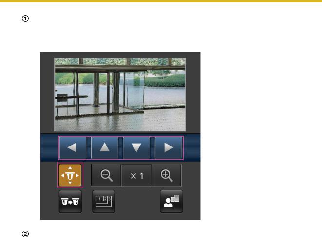
1.2.2 Monitor images on a mobile terminal (including smartphones)
It is possible to connect to the camera using a mobile terminal via the Internet and monitor images (MJPEG or JPEG) from the camera on the screen of the mobile terminal. It is also possible to refresh images to display the latest image.
The compatible mobile terminals are shown as follows. (As of July, 2017)
–iPad, iPhone (iOS 4.2.1 or later)
–Android™ mobile terminals
When an Android terminal is used, an MJPEG format image is displayed by the Firefox® browser, and a JPEG format image is displayed by the standard browser.
For further information about compatible devices, refer to our website (https://security.panasonic.com/support/info/).
IMPORTANT
•When the authentication window is displayed, enter the user name and password.
To enhance the security, it is recommended to change the password periodically. (®page 177)
Note
•It is necessary to configure the network settings of the mobile terminal in advance to connect to the Internet and monitor images from the camera. (®page 185)
1.Access to “http://IP address/cam”*1 or “http://Host name registered in the DDNS server/cam”*2 using a mobile terminal.
→ Images from the camera will be displayed.
A
B
C
D
Operating Instructions |
23 |
|
|

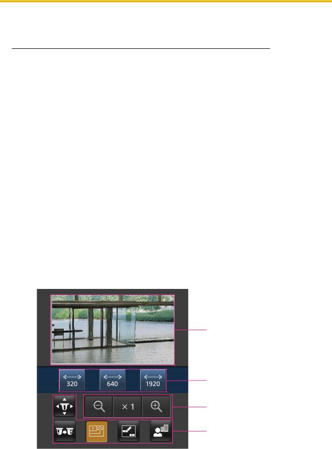
1 Operations
Live images area
Displays images from the camera. Operation buttons area
When functions are selected in the function selection area D, buttons to operate those functions are displayed.
Zoom operation area
Buttons to operate the zoom are displayed. Function selection area
When functions that can be operated are selected, operation buttons are displayed in the operation buttons area B.
Note
•The operations button displayed on the mobile terminal screen may not be available depending on the user rights and access level of the accessing user. To display the operations button, it is necessary to set the user rights and access level (“User auth.” in “User mng.”). (®page 177)
2.Click the button of the function that you want to operate.
A |
F |
B C D E
Pan/Tilt
Preset
Resolution control
AUX control
Focus display
Zoom display
Each function is explained below.
24 Operating Instructions
1 Operations
Pan/Tilt
Press the  button to display the buttons used to operate pan/tilt on the screen. The pan/tilt can be adjusted in each direction with the
  ,
,  ,
,  , and
, and  buttons.
Preset
Press the  button to display the buttons used to select the preset position on the screen. Camera
images are displayed of the registered preset camera directions according to the preset numbers selected from the buttons.
•Only position numbers 1-4 for the preset positions are displayed.
•Only registered preset positions are displayed. Unregistered preset positions are not displayed.
Operating Instructions |
25 |
|
|

1 Operations
Resolution control
Press the  button to display the buttons used to select the resolution on the screen. The resolution
can be changed by selecting a resolution setting from the buttons.
Images are displayed in the image capture size selected in “JPEG(1)”, “JPEG(2)”, or “JPEG(3)” of [JPEG] on the [Image] tab.
26 Operating Instructions

1 Operations
AUX control
Press the  button to display the buttons used to operate the AUX output on the screen. The AUX output terminals can be controlled with the
  and
and  buttons.
This function is only displayed when [Terminal 3] is set to [AUX output] on the settings menu. (®Page 57)
Operating Instructions |
27 |
|
|

1 Operations
Focus display
Press the  button to display the buttons used to operate the focus on the screen. The camera’s focus can be operated with the
  ,
,  , and
, and  buttons.
Zoom display
The camera’s zoom can be operated with the  ,
,  , and
, and  buttons.
28 Operating Instructions

1 Operations
Note
•You can change the image size displayed on the mobile terminal by accessing the following addresses.
–Large display: http://IP address/cam/dl
–Medium display: http://IP address/cam/dm
–Small display: http://IP address/cam/ds
•When the resolution is changed by the resolution control, the displayed resolution changes but the image size remains the same.
•When the HTTP port number is changed from “80”, enter “http://IP address: (colon) + port number/ cam”*1 in the address box of the browser. When using the DDNS function, access to “http://Host name registered in the DDNS server: (colon) + port number/cam”*2.
•When “HTTPS” is selected for “HTTPS” - “Connection” on the [Advanced] tab of the “Network” page, enter as follows.
“https://IP address: (colon) + port number/cam” or “https://Host name registered in the DDNS server: (colon) + port number/cam”
•When the authentication window is displayed, enter the user name of an administrator or user and password. Depending on the mobile terminal in use, password entry may be required each time the screen is switched.
•It is impossible to send and receive audio using a mobile terminal.
•Depending on the mobile terminal in use, larger size images may not be displayed. In this case, selecting a setting close to the lowest quality setting for “Image quality setting” of “JPEG” (®page 96) may sometimes solve this problem.
•Depending on the mobile terminal in use or its contract plan, it may be impossible to access.
*1
*2
IP address is the global WAN IP address of the router that can be accessed via the Internet. However, when accessing the same LAN as the camera with a wireless compatible mobile terminal, the IP address is the local IP address.
Only when accessing the camera via the Internet.
Operating Instructions |
29 |
|
|

1 Operations
1.3 Record images on the SD memory card manually
Images displayed on the “Live” page can be recorded on the SD memory card manually. This button is operable only when “Manual” is selected for “Save trigger” on the [SD memory card] tab on the “Basic” page of the setup menu. (®page 81)
It is possible to select “JPEG(1)”, “JPEG(2)”, “JPEG(3)”, “Stream(1)”, “Stream(2)”, “Stream(3)”, or “Stream(4)” on “Recording format” of the setup menu. (®page 80) When “JPEG” is selected for “Recording format”, still image data are recorded. When “Stream(1)”, “Stream(2)”, “Stream(3)”, or “Stream(4)” is selected, video data are recorded.
Images recorded on the SD memory card can be copied onto the PC. (®page 91) 1. Display the “Live” page. (®page 9)
2.Click the [Rec. on SD] button.
→ The SD recording window will open.
3.Click the [Start] button to start recording images on the SD memory card. The SD recording status indicator will light red (®page 12) while images are being recorded on the SD memory card.
The image saving interval can be configured on the [SD memory card] tab of the “Basic” page. (®page 78)
4.Click the [Stop] button to stop saving images on the SD memory card. ® The SD recording status indicator will turn off.
5.Click the [Close] button to close the window.
Note
•Image data saved on Drive B can be obtained by executing “Access img.” on the [SD memory card] tab and logging in from the user authentication window (®page 91).
The destination to save image data is a fixed directory on Drive B (®page 270).
30 Operating Instructions
Loading...