


WV-Q122A
Before attempting to connect or operate this product,
please read these instructions carefully and save this manual for future use.
The model number is abbreviated in some descriptions in this manual.
Operating Instructions
Included Installation Instructions
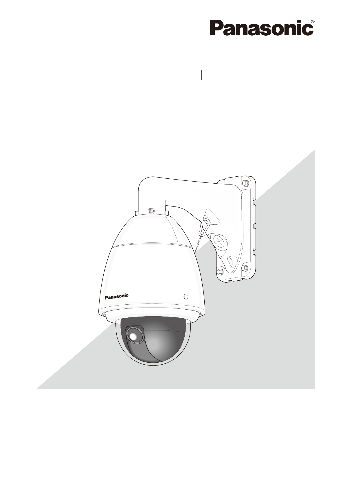
Wall Mount Bracket
Model No. WV-Q122A
The camera in the illustration is separately sold.

2
Preface ......................................................................................................................................................................................3
Precautions ...............................................................................................................................................................................3
Precautions for installation ........................................................................................................................................................4
Major operating controls ...........................................................................................................................................................5
Installations/Connections ..........................................................................................................................................................6
Specifications ..........................................................................................................................................................................14
Standard accessories ..............................................................................................................................................................14
CONTENTS

3
Preface
This mount bracket is used for installing the color CCTV camera and network camera on a wall.
Refer to the catalog or operating instructions of the camera for further information about the compatible models.
Precautions
Refer installation work to the dealer.
Installation work requires technique and experiences.
Failure to observe this may cause fire, electric shock, injury,
or damage to the product.
Be sure to consult the dealer.
Avoid installing this bracket in the locations where
salt damage occurs or corrosive gas is produced.
Otherwise, the mounting portions will deteriorate and acci-
dents such as a fall of this product may occur.
The screws and bolts must be tightened to the speci-
fied torque.
Loosening of mounting screws or bolts may cause a fall of
the product resulting in injury or accidents.
Do not use this bracket except with suitable cameras
Failure to observe this may cause a drop resulting in injury.
Select an installation area that can support the total
weight.
Selecting an inappropriate installation surface may cause
this product to fall down or topple over, resulting in injury or
accidents.
Installation work shall be started after sufficient reinforce-
ment.
Do not rub the edges of metal parts with your hand.
Strong rubbing may cause injury.
Periodic inspections shall be conducted.
Rust on the metal parts or screws may cause a fall of the
product resulting in injury or accidents.
Consult the dealer for the inspections.
The measures of protection against a fall of this prod-
uct shall be taken.
Failure to observe this may cause a drop resulting in injury
or accidents.
Be sure to install the safety wire.
Do not install this product in locations subject to
vibration.
Loosening of mounting screws or bolts may cause a fall of
the product resulting in injury or accidents.
Do not strike or give a strong shock to this product.
Failure to observe this may cause fire or injury.
Install this product in a location high enough to avoid
people and objects from bumping the product.
Failure to observe this may cause injury.
Do not hang down from this product or use this prod-
uct as a pedestal.
Failure to observe this may cause a drop resulting in acci-
dents.
Do not install the product in a windy place.
Installation of the product in wind with a speed of 40 m/s or
more may cause a drop resulting in accidents.
The measures of protection against snowfall shall be
taken.
Weight of snow may cause a fall of the product resulting in
injury or accidents.
Protect the product against snowfall by installing under
eaves.

4
Precautions for installation
Panasonic assumes no responsibility for injuries or property damage resulting from failures arising out of improper
installation or operation inconsistent with this documentation.
The installation should comply with local electrical
code.
Before start the installation/connection, check and prepare
the required devices and cables. Before starting the con-
nection, turn the power of the devices including the camera
and the PC off.
Refer installation work to the dealer. Failure to
observe this may cause fire, electric shock, injury, or
damage to the product.
Power supply
Use a power supply device equipped with the ON-OFF
switch for servicing. When the power cord of the product is
connected to the power supply device, the power will be
supplied to the product. When the product is supplied, the
product will perform panning, tilting, zooming and focusing.
Before cleaning the product, make sure that the power
cable is not connected to the main power supply.
Installation area for this product
Consult the dealer about the installation area to select a
strong wall area.
Screws used for installing this product on a wall are not •
supplied. Prepare them according to the material and
strength of the area where the product is to be installed.
Recommended screw: M8 x 4 pcs.
Minimum pull-out strength (per 1 pc.): 823 N {185 lbf}
Do not mount the product on a plaster board or a •
wooden section because they are too weak. If the prod-
uct is unavoidably mounted on such a section, the sec-
tion shall be sufficiently reinforced.
Mounting method for this product
This product is designed to be used as a pendant mount
camera. If the product is mounted on a desktop or at a
slant, it may not work correctly and its lifetime may be short-
ened.
Protection from lightning
When cables are used outdoors, there is a chance that they
may be affected by lightning. In this case, install a lightning
arrester just before where the cables connect to the cam-
era.
Do not place this product in the following places:
Locations where a chemical agent is used such as a •
swimming pool
Locations subject to moisture or oil smoke such as a •
kitchen
Locations that have a specific environment that is sub-•
ject to an inflammable atmosphere or solvents
Locations where radiation, x-ray, intense radio wave, or •
strong magnetism is produced
Locations where corrosive gas is produced, locations •
where it may be damaged by briny air such as sea-
shores
Locations where the temperature is not within the speci-•
fied range (–50 °C to +55 °C {–58 °F to 131 °F})
Locations subject to vibrations, such as on vehicles, •
marine vessels, or above product lines (This product is
not designed for onvehicle use.)
Locations subject to condensation as the result of •
severe changes in temperature (In case of installing the
product in such locations, the dome cover may become
foggy or condensation may be caused on the cover.)
Screw tightening
The screws and bolts must be tightened with an appro-•
priate tightening torque according to the material and
strength of the installation area.
Do not use an impact driver. Use of an impact driver •
may damage the screws or cause tightening exces-
sively.
When a screw is tightened, make the screw at a right •
angle to the surface. After tightening the screws or
bolts, perform checks to ensure that the tightening is
sufficient enough so that there is no movement or loose-
ness.
The protection cover attached to the camera unit
shall be removed after completion of the installation.
(rain wash coating model)
Make sure to remove this product if it will no longer
be used.
Take notice of humidity.
Install this product when the humidity is low. If this product
is installed during rainfall or at a high humidity, the inside
may be exposed to moisture and the dome cover may
become foggy.
Matters you should know at installation work
Compatibility of devices are restricted. Before connections,
check the ratings and dimensions of the devices to be used.
Refer to "Panasonic CCTV System General Catalog" or con-
tact your dealer for further information.

5
Major operating controls
Hexagonal screw hole for
mounting camera
(4 points)
Wire hook section
Camera mounting part
Cable access hole (front)
Plate
Cable access hole
(rear)
220 mm {8-21/32 inches}
269 mm {10-19/32 inches}
120 mm
{4-23/32 inches}
 Loading...