


 Loading...
Operating Instructions
Network Camera
Model No. WV-SW598
WV-SW598J
WV-SC588
|
|
|
WV-SW598 |
WV-SC588 |
|
Before attempting to connect or operate this product, please read these instructions carefully and save this manual for future use.
The model number is abbreviated in some descriptions in this manual.

Preface
Preface
About the user manuals
There are 2 sets of operating instructions as follows.
•Operating Instructions: Explains how to perform the settings and how to operate this camera.
•Installation Guide: Explains how to install and connect devices.
The screens used in these operating instructions show the case of WV-SW598. Depending on the model used, the screens shown in the explanations may differ to the actual camera screens.
About notations
The following notations are used when describing the functions limited for specified models. The functions without the notations are supported by all models.
SW598 : The functions with this notation are available when using the model WV-SW598.
SC588 |
: The functions with this notation are available when using the model WV-SC588. |
Trademarks and registered trademarks
•Microsoft, Windows, Windows Vista, Windows Media, Internet Explorer, ActiveX and DirectX are either registered trademarks or trademarks of Microsoft Corporation in the United States and/or other countries.
•Microsoft product screen shot(s) reprinted with permission from Microsoft Corporation.
•iPad, iPhone, iPod touch, and QuickTime are trademarks of Apple Inc., registered in the U.S. and other countries.
•Android is a trademark of Google Inc.
•Firefox is a registered trademark of the Mozilla Foundation.
•SDXC Logo is a trademark of SD-3C, LLC.
•All other trademarks identified herein are the property of their respective owners.
Abbreviations
The following abbreviations are used in these operating instructions. Microsoft® Windows® 8 is described as Windows 8.
Microsoft® Windows® 7 is described as Windows 7. Microsoft® Windows Vista® is described as Windows Vista. Microsoft® Windows® XP SP3 is described as Windows XP.
Windows® Internet Explorer® 10.0, Windows® Internet Explorer® 9.0, Windows® Internet Explorer® 8.0 and Windows® Internet Explorer® 7.0 are described as Internet Explorer.
SDXC/SDHC/SD memory card is described as SD card or SD memory card. Universal Plug and Play is described as UPnP™.
2Operating Instructions

Preface
Viewer software
It is necessary to install the viewer software “Network Camera View 4S” (ActiveX®) to display images on a PC. This software can be installed directly from the camera or by selecting the [Install] button next to [Viewer Software] on the menu of the CD-ROM provided, and then following the on-screen instructions.
IMPORTANT
•The default setting of “Automatic installation of viewer software” is “On”. Follow the instructions on page 223 when the message is displayed on the information bar of the browser.
•When the “Live” page is displayed for the first time, the install wizard of the ActiveX control required to display images from the camera will be displayed. Follow the instructions of the wizard.
•When the install wizard is displayed again even after completing the installation of the ActiveX, restart the PC.
•The viewer software used on each PC should be licensed individually. The number of installations of the viewer software from the camera can be checked on the [Upgrade] tab of the “Maintenance” page (®page 197). Refer to your dealer for the software licensing.
Operating Instructions |
3 |
|
|

Table of Contents
Table of Contents
1 Monitor images on a PC .......................................................................... |
7 |
|
1.1 |
Monitor images from a single camera ............................................................................. |
7 |
1.2 |
About the “Live” page ...................................................................................................... |
9 |
1.3 |
Monitor images from multiple cameras ........................................................................ |
15 |
2 |
Monitor images on a cellular phone/mobile terminal |
.........................17 |
2.1 |
Monitor images on a cellular phone .............................................................................. |
17 |
2.2 |
Monitor images on a mobile terminal ............................................................................ |
20 |
3 |
Record images on the SD memory card manually ............................. |
28 |
4 |
Action at an alarm occurrence .............................................................. |
30 |
4.1 |
Alarm type ........................................................................................................................ |
30 |
4.2 |
Action at an alarm occurrence ....................................................................................... |
30 |
5 |
Transmit images onto an FTP server ................................................... |
32 |
5.1Transmit an alarm image at an alarm occurrence (Alarm image
transmission) |
...................................................................................................................32 |
5.2Transmit images at a designated interval or period (FTP periodic image
transmission) |
...................................................................................................................32 |
5.3Save images on the SD memory card when images fail to transmit using the FTP
|
periodic image transmission function .......................................................................... |
33 |
6 Display the log list ................................................................................. |
34 |
|
6.1 |
When “JPEG” is selected for “Recording format” of the SD memory card .............. |
34 |
6.2When “H.264(1)” or “H.264(2)” is selected for “Recording format” of the SD memory
|
card ................................................................................................................................... |
37 |
7 Playback of images on the SD memory card ...................................... |
41 |
|
7.1 |
When “JPEG” is selected for “Recording format” of the SD memory card .............. |
41 |
7.2When “H.264(1)” or “H.264(2)” is selected for “Recording format” of the SD memory
|
card ................................................................................................................................... |
44 |
8 About the network security ................................................................... |
46 |
|
8.1 |
Equipped security functions .......................................................................................... |
46 |
9 Display the setup menu from a PC ....................................................... |
47 |
|
9.1 |
How to display the setup menu ..................................................................................... |
47 |
9.2 |
How to operate the setup menu ..................................................................................... |
49 |
9.3 |
About the setup menu window ...................................................................................... |
51 |
10 Configure the basic settings of the camera [Basic] ........................... |
53 |
|
10.1 |
Configure the basic settings [Basic] ............................................................................. |
53 |
10.2 |
Configure the Internet settings [Internet] ..................................................................... |
57 |
10.3 |
Configure the settings relating to the SD memory card [SD memory card] .............. |
59 |
10.4Access copy images saved on the SD memory card onto the PC [SD memory card
|
images] ............................................................................................................................. |
68 |
10.5 |
Configure the settings relating to the logs [Log] ......................................................... |
76 |
10.5.1 |
How the logs and images are saved depending on the settings for “Alarm” .................. |
78 |
10.5.2How the logs and images are saved depending on the settings for “Manual/
|
Schedule” ....................................................................................................................... |
79 |
10.5.3 |
How the logs and images are saved depending on the settings for “FTP error” ............ |
81 |
4Operating Instructions

|
Table of Contents |
|
11 Configure the settings relating to images and audio [Image/ |
|
|
Audio] ...................................................................................................... |
82 |
|
11.1 |
Configure the settings relating to the image capture mode [JPEG/H.264] ................ |
82 |
11.2 |
Configure the settings relating to JPEG images [JPEG/H.264] .................................. |
83 |
11.3 |
Configure the settings relating to H.264 images [JPEG/H.264] .................................. |
85 |
11.4 |
Configure the settings relating to the camera operations [Cam. Function] .............. |
91 |
11.5Configure the settings relating to images and the preset positions [Image/
|
Position] ........................................................................................................................... |
95 |
11.5.1 |
Configure the settings relating to image quality (“Image adjust” setup menu) ............... |
96 |
11.5.2 |
Set mask areas ............................................................................................................ |
103 |
11.5.3Configure the settings relating to the preset positions (“Preset position” setup
|
menu) ........................................................................................................................... |
106 |
11.5.4 |
Configure the settings relating to the auto pan function (“Auto pan” setup menu) ....... |
109 |
11.5.5 |
Configure the settings relating to patrol (“Patrol” setup menu) ..................................... |
111 |
11.5.6 |
Configure the settings relating to auto track (“Auto track” setup menu) ....................... |
113 |
11.5.7 |
Configure the settings relating to direction (“Direction” setup menu) ........................... |
119 |
11.5.8 |
Configure the settings relating to the privacy zone (“Privacy zone” setup menu) ........ |
120 |
11.5.9 |
Configure the VIQS setting (“VIQS” setup menu) ........................................................ |
122 |
11.6 |
Configure the settings relating to audio [Audio] ....................................................... |
125 |
12 Configure the multi-screen settings [Multi-screen] .......................... |
128 |
|
13 Configure the alarm settings [Alarm] ................................................. |
130 |
|
13.1 |
Configure the settings relating to the alarm action [Alarm] ..................................... |
130 |
13.2Configure the settings relating to the camera action on alarm occurrence
[Alarm] |
............................................................................................................................132 |
13.2.1Configure the settings relating to Preset per sender (“Preset per sender” setup
|
menu) ........................................................................................................................... |
133 |
13.3 |
Configure the settings relating to the alarm image [Alarm] ...................................... |
134 |
13.4 |
Configure the settings relating to H.264 recording [Alarm] ...................................... |
136 |
13.5 |
Configure the settings relating to the alarm output terminal [Alarm] ...................... |
137 |
13.6 |
Change the AUX name [Alarm] .................................................................................... |
138 |
13.7 |
Configure the VMD settings [VMD area] ..................................................................... |
139 |
13.8 |
Configure the settings relating to the audio detection [Audio detection] ............... |
142 |
13.9 |
Configuration of the settings relating to the E-mail notification [Notification] ....... |
145 |
13.10 |
Configure the settings relating to Panasonic alarm protocol [Notification] ........... |
146 |
14 Configure the setting relating to the image recognition [Advanced |
|
|
func.] ..................................................................................................... |
149 |
|
14.1 |
Configure the settings relating to the XML notification [XML notification] ............. |
149 |
15 Configure the settings relating to the authentication [User |
|
|
mng.] ..................................................................................................... |
151 |
|
15.1 |
Configure the settings relating to the user authentication [User auth.] .................. |
151 |
15.2 |
Configure the settings relating to the host authentication [Host auth.] .................. |
152 |
15.3 |
Configure the settings relating to the priority stream [System] ............................... |
153 |
16 Configure the settings of the servers [Server] .................................. |
156 |
|
16.1 |
Configure the settings relating to the E-mail server [E-mail] ................................... |
156 |
16.2 |
Configure the settings relating to the FTP server [FTP] ........................................... |
157 |
16.3 |
Configure the settings relating to the NTP server [NTP] ........................................... |
158 |
17 Configuring the network settings [Network] ..................................... |
161 |
|
17.1 |
Configure the network settings [Network] .................................................................. |
161 |
Operating Instructions |
5 |
|
|

Table of Contents
17.2 |
Configure the HTTPS settings ..................................................................................... |
169 |
17.2.1 |
Generation of the CRT key (SSL encryption key) ........................................................ |
170 |
17.2.2 |
Generation of the self-signed certificate (security certificate) ....................................... |
171 |
17.2.3 |
Generation of CSR (Certificate Signing Request) ........................................................ |
173 |
17.2.4 |
Installation of the server certificate ............................................................................... |
174 |
17.2.5 |
Configuration of the connection protocol ...................................................................... |
175 |
17.3 |
Access the camera using the HTTPS protocol .......................................................... |
176 |
17.3.1 |
Install the security certificate ........................................................................................ |
176 |
17.4 |
Configure the settings relating to DDNS [DDNS] ....................................................... |
183 |
17.4.1 |
Configuration of the DDNS service (Example of the “Viewnetcam.com” service) ........ |
184 |
17.4.2 |
When using the “Viewnetcam.com” service ................................................................. |
186 |
17.4.3 |
Procedure to register information for the “Viewnetcam.com” service ........................... |
186 |
17.4.4 |
Checking the information registered for the “Viewnetcam.com” service ...................... |
188 |
17.4.5 |
When using “Dynamic DNS Update” ............................................................................ |
188 |
17.4.6 |
When using “Dynamic DNS Update(DHCP)” ............................................................... |
188 |
17.5 |
Configure the settings relating to SNMP [SNMP] ...................................................... |
189 |
17.6Configure the settings relating to the FTP periodic image transmission [FTP img.
trans.] |
.............................................................................................................................190 |
17.7Configure the schedule settings of the FTP periodic image transmission [FTP img.
|
|
trans.] ............................................................................................................................. |
191 |
17.7.1 How to set the schedules ............................................................................................. |
192 |
||
17.7.2 How to delete the set schedule .................................................................................... |
193 |
||
18 |
Configure the settings relating to the schedules [Schedule] .......... |
194 |
|
19 |
Maintenance of the camera [Maintenance] ........................................ |
197 |
|
19.1 |
Check the system log [System log] ............................................................................. |
197 |
|
19.2 |
Upgrade the firmware [Upgrade] ................................................................................. |
197 |
|
19.3 |
Check the status [Status] ............................................................................................. |
199 |
|
19.4 |
Reset the settings/Reboot the camera [Default reset] ............................................... |
200 |
|
20 |
Number of users that can concurrently access the unit .................. |
202 |
|
21 |
Using the CD-ROM ............................................................................... |
203 |
|
21.1 |
About the CD launcher ................................................................................................. |
203 |
|
21.2 |
Installing Panasonic “IP Setting Software” ................................................................ |
204 |
|
21.3 |
Installing the manuals .................................................................................................. |
205 |
|
21.4 |
Installing the Viewer software ...................................................................................... |
205 |
|
21.5Configure the network settings of the camera using the Panasonic “IP Setting
|
Software” ....................................................................................................................... |
206 |
22 |
About the displayed system log ......................................................... |
209 |
23 |
Troubleshooting ................................................................................... |
213 |
24 |
Directory structure of drive B ............................................................. |
225 |
6Operating Instructions
1 Monitor images on a PC
1 Monitor images on a PC
The following are descriptions of how to monitor images from the camera on a PC.
1.1 Monitor images from a single camera
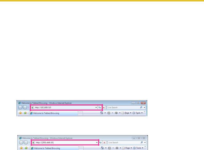
1.Start up the web browser.
2.Enter the IP address designated using the Panasonic “IP Setting Software” in the address box of the browser.
•Example when entering an IPv4 address: http://URL registered using IPv4 address http://192.168.0.10/
•Example when entering an IPv6 address: http://[URL registered using IPv6 address] http://[2001:db8::10]/
<Example of IPv4 access>
<Example of IPv6 access>
IMPORTANT
•When the HTTP port number is changed from “80”, enter “http://IP address of the camera + : (colon) + port number” in the address box of the browser. (Example: http://192.168.0.11:8080)
•When the PC is in a local network, configure the proxy server setting of the web browser (under [Internet Options...] under [Tools] of the menu bar) to bypass the proxy server for the local address.
Note
•Refer to page 176 for further information about the case in which “HTTPS” is selected for “HTTPS” - “Connection” on the [Network] tab of the “Network” page (®page 161).
Operating Instructions |
7 |
|
|
1 Monitor images on a PC
3.Press the [Enter] key on the keyboard.
→ The “Live” page will be displayed. Refer to page 9 for further information about the “Live” page.
When “On” is selected for “User auth.”, the authentication window will be displayed before displaying live images for the user name and password entries. The default user name and password are as follows. User name: admin
Password: 12345
IMPORTANT
•To enhance the security, change the password for the user name “admin”. It is recommended to change this password periodically.
•When displaying multiple H.264 images on a PC, images may not be displayed depending on the performance of the PC.
Note
•The maximum number of concurrent access user is 14 including users who is receiving H.264 images and users who are receiving JPEG images. Depending on the set values for “Bandwidth control(bit rate)” and “Max bit rate (per client)”, the maximum concurrent access number may be 14 or less users. When 14 users are concurrently accessing, the access limit message will be displayed for users who subsequently attempt to access. When “Multicast” is selected for “Transmission type” of “H.264”, only the first user who accessed to monitor H.264 images will be included in the maximum number. The second and subsequent users who are monitoring H.264 images will not be included in the maximum number.
•When “On” is selected for “H.264 transmission” (®page 87), H.264 images will be displayed. When “Off” is selected, a JPEG image will be displayed. It is possible to display a JPEG image even when “On” is selected for “H.264 transmission”. In this case, the refresh interval of JPEG images will be limited to 5 fps.
•The refresh interval may become longer depending on a network environment, PC performance, photographic subject, access traffic, etc.
<Refresh interval of JPEG images>
When “On” is selected for “H.264 transmission”
Max. 5fps
When “Off” is selected for “H.264 transmission”
Max. 30fps
8Operating Instructions

1 Monitor images on a PC
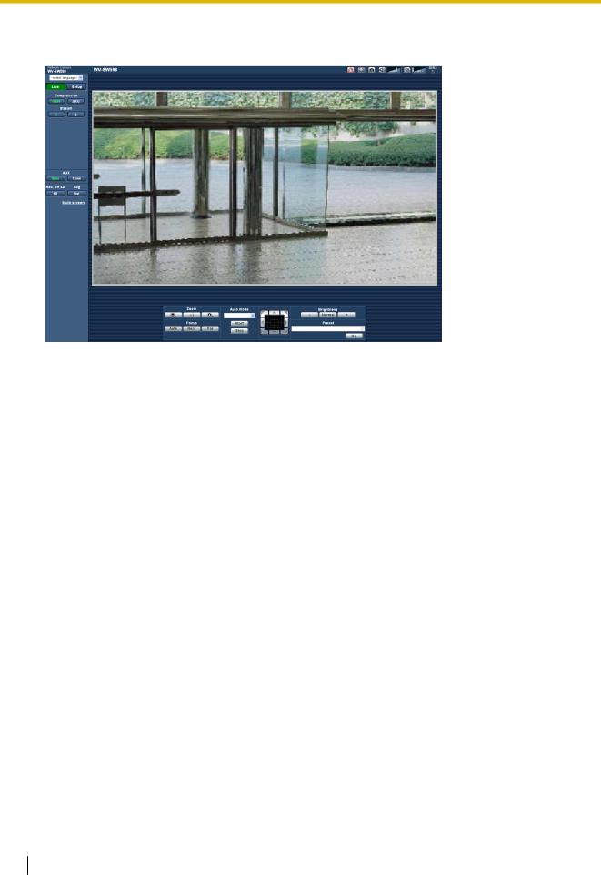
1.2 About the “Live” page
R S T U V W X
A
B
C
D
E
F
G
H
I
J
K
L M N O
Y
P
Q
[select language] pull-down-menu
The camera’s display language can be selected. The default language can be set in the [Language] in the [Basic] settings. (®page 53)
[Setup] button*1
Displays the setup menu. The button will turn green and the setup menu will be displayed.
[Live] button
Displays the “Live” page. The button will turn green and the “Live” page will be displayed.
[Compression] buttons
•[H.264] button: The characters “H.264” on the button will turn green and an H.264 image will be displayed. When “On” is selected for “H.264 transmission” of “H.264(1)”, “H.264(2)”, the [H.264] button will be displayed. (®page 87)
•[JPEG] button: The characters “JPEG” on the button will turn green and a JPEG image will be displayed.
[Stream] buttons
These buttons will be displayed only when an H.264 image is displayed.
•[1] button: The character “1” will turn green and images in the main area will be displayed in accordance with the setting of “H.264(1)”. (®page 87)
•[2] button: The character “2” will turn green and images in the main area will be displayed in
accordance with the setting of “H.264(2)”. (®page 87)
[Image capture size] buttons
These buttons will be displayed only when a JPEG image is displayed.
Operating Instructions |
9 |
|
|

1 Monitor images on a PC
[VGA] |
The characters “VGA” will turn green and images in the main area will be |
|
displayed in VGA size. |
|
|
[QVGA] |
The characters “QVGA” will turn green and images in the main area will be |
|
displayed in QVGA size. |
|
|
[1280x960] |
The characters “1280x960” will turn green and images in the main area will be |
|
displayed in 1280 x 960 (pixels). |
|
|
[640x360] |
The characters “640x360” will turn green and images in the main area will be |
|
displayed in 640 x 360 (pixels). |
|
|
[320x180] |
The characters “320x180” will turn green and images in the main area will be |
|
displayed in 320 x 180 (pixels). |
|
|
[1280x720] |
The characters “1280x720” will turn green and images in the main area will be |
|
displayed in 1280 x 720 (pixels). |
|
|
[1920x1080] |
The characters “1920x1080” will turn green and images in the main area will be |
|
displayed in 1920 x 1080 (pixels). |
|
|
Note
•The buttons [VGA], [QVGA], and [1280x960] are displayed only when “1.3 mega pixel [4:3]” is selected for “Image capture mode”.
•The buttons [640x360] and [320x180] are displayed only when “2 mega pixel [16:9]” or “1.3 mega pixel [16:9]” is selected for “Image capture mode”.
•The button [1280x720] is displayed only when “1.3 mega pixel [16:9]” is selected for “Image capture mode”.
•The button [1920x1080] is displayed only when “2 mega pixel [16:9]” is selected for “Image capture mode”.
•When “1920x1080”, “1280x960”, or “1280x720” is selected for the image capture size, it may become smaller than the actual size depending on the window size of the web browser.
[Image quality] buttons
These buttons will be displayed only when a JPEG image is displayed.
•[1] button: Images in the main area will be displayed in accordance with the setting for “Quality1” of “Image quality setting”. (®page 83)
•[2] button: Images in the main area will be displayed in accordance with the setting for “Quality2” of
“Image quality setting”. (®page 83)
[AUX] buttons*2
These buttons will be displayed only when “Terminal 3” of “Alarm” is set to “AUX output” on the setup menu. (®page 130)
•[Open] button: The characters “Open” on the button will turn green and the status of the AUX connector will be open.
•[Close] button: The characters “Close” on the button will turn green and the status of the AUX connector will be closed.
Note
•The names of “AUX”, “Open” and “Close” can be changed. (®page 138)
[Rec. on SD] button*2
This button will be displayed only when “Manual” is selected for “Save trigger” on the setup menu. (®page 62)
Click this button to manually record images on the SD memory card. Refer to page 28 for descriptions of how to manually record images on the SD memory card.
10 Operating Instructions
1 Monitor images on a PC
[Log] button*1
[List] button will become available only when “On” is selected for “Save logs” on the setup menu. (®page 76)
When this button is clicked, the log list will be displayed and images saved on the SD memory card can be played. Refer to page 34 for further information about the log list and for how to play images on the SD memory card.
[Multi-screen]
Images from multiple cameras can be displayed on a multi-screen by registering cameras on the setup menu. (®page 15)
[Zoom] buttons*2
• : Click this button to adjust the zoom ratio to the “Wide” side.
• : Click this button to set the zoom ratio to x1.0.
• : Click this button to adjust the zoom ratio to the “Tele” side.
[Focus] buttons*2
• : Click this button to adjust the focus automatically.
• : Click this button to adjust the focus to the “Near” side.
• : Click this button to adjust the focus to the “Far” side.
Note
•When shooting the following place or the following subjects, focus may not be adjusted automatically. Adjust the focus manually.
–Shiny or strongly reflective subject
–Subject through the glass with dew or smudge
–Two subjects whose distances from the camera are different
–Less contrast subject (e.g. white wall)
–Horizontal-striped subject such as a window blind
–Inclined subject
–Dark subject
[Auto mode]*2
Select an operation from the pull-down menu and click the [Start] button. The selected operation will start. Click the [Stop] button to stop the operation.
The selected operation will stop when the camera (panning/tilting/zooming/focusing) is operated or when an action that is to be taken according to the settings for “Self return” (®page 91) or for “Camera action on alarm” (®page 132) starts.
•Auto track: Automatically tracks objects in the shooting area.
Note
•With the Auto track feature, objects moving in the screen are picked out and automatically tracked.
•In the following situations, targets may not be able to be tracked, or false detections may occur.
–when there is little contrast between the subject and the background
–when the dome is dirty or wet
–when there are large changes to the lighting intensity
–when there are many moving objects other than the subject
–when there is a change to the axis of the camera’s lens
–when the subject moves directly underneath the camera
–when there is harsh flickering
–when there are reflections from light entering the dome due to reflections from a window or road, or from a backlight
–when the target is hidden behind a utility pole or other objects
Operating Instructions |
11 |
|
|

1 Monitor images on a PC
–when the subject passes by other moving objects
–when the target moves too fast or too slow
–when the camera is shaking
•When the zoom ratio is set to the “Tele” side, it may be difficult to obtain accuracy with the auto tracking function. It is recommended to use the auto tracking function with setting the zoom ratio to the “Wide” side.
•During auto tracking, if the camera is operated using the control pad or by other methods, or if an alarm occurs, auto tracking is stopped.
•Auto pan: Automatically pans between the start position and the end position set in advance (®page 109).
Even when the camera is operated for zooming or focusing, the camera continues panning. (However, panning will stop when the zoom button (x1) is clicked.)
•Preset sequence: Automatically moves to the preset positions (®page 106) orderly (start from the lowest preset position number).
•360 map-shot: Moves 45° horizontally at a time and repeats 8 times to shoot images of each 45° position (45° x 8 = 360°), and then displays 8 thumbnail images of each 45° position (45° x 8 = 360°) on a newly opened window. When a thumbnail image is clicked, the camera moves to the respective position and live images will be displayed on the “Live” page.
•Preset map-shot: 8 thumbnail images of the preset position 1-8 (®page 106) will be displayed orderly on a newly displayed window. When a thumbnail image is clicked, the camera moves to the respective position and live images will be displayed on the “Live” page.
Note
•Do not operate the browser until all the thumbnail images are displayed and the camera returns to the original position (where the camera was when “360 map-shot” or “Preset map-shot” was carried out).
•When “360 map-shot” is carried out while the camera is moving (panning/tilting), images captured while panning/tilting may be displayed as the thumbnail display. In this case, stop the current operation and carry out “360 map-shot” again.
•When “Preset map-shot” is carried out with an unregistered preset position (among preset position 1-8), the thumbnail image of the preset position before the unregistered preset position will be displayed.
In this case, the camera will not move when the thumbnail image is clicked.
•The camera will not always return to the exactly same position where it was before “360 map-shot” or “Preset map-shot” was carried out. (It may sometimes be slightly different.)
•The window on which the thumbnail images are displayed will close when clicking the following buttons that can switch the camera channel or reload images: [Live], [Multi-screen], [H.264], [JPEG], [Stream], [Image capture size], [Image quality], [Setup].
To display the thumbnail images again, carry out “360 map-shot” or “Preset map-shot” again.
•Patrol 1-4: Performs patrols 1-4 that were set in advance. (®page 111)
Control pad/buttons*2
Left-click on the control pad or buttons to adjust the horizontal/vertical position of the camera (panning/ tilting). Panning/tilting speed will be faster if a clicked point gets farther from the center point of the control pad. When the tilt reaches a certain angle, the image is automatically turned upside-down (digital flip function).
It is also possible to pan/tilt the camera by dragging the mouse.
Zoom and focus can be adjusted by right-clicking. When an upper/lower area of the control pad is right-clicked, the displayed image will be zoomed in/out on. When a left/right area is right-clicked, the focus will be adjusted to the Near/Far side.
Zoom can also be adjusted using the mouse wheel.
[Brightness] buttons*2
Available range: 0 - 255
12 Operating Instructions

1 Monitor images on a PC
• button: Images become darker.
• button: The adjusted brightness will return to the default brightness (64).
• button: Images become brighter.
[Preset]*2
Select a preset position from the pull-down menu and click the [Go] button. The camera will move to the selected preset position (®page 106). “H” next to the preset position number indicates the home position. When “Home position” is selected, the camera will move to the home position. (®page 91)
When “Preset ID” is registered for a preset position, the registered preset ID will be displayed next to the preset position number.
Camera title
The camera title entered for “Camera title” on the [Basic] tab will be displayed. (®page 53)
Alarm occurrence indication button*2
This button will be displayed and will blink when an alarm has occurred. When this button is clicked, the alarm output terminal will be reset and this button will disappear. (®page 30)
Full screen button
Images will be displayed on a full screen. To return to the “Live” page, press the [Esc] key. The aspect ratio of displayed images will be adjusted in accordance with the monitor.
Snap shot button
Click this button to take a picture (a still picture). The picture will be displayed on a newly opened window. When right-clicking on the displayed image, the pop-up menu will be displayed. It is possible to save the image on the PC by selecting “Save” from the displayed pop-up menu.
When “Print” is selected, printer output is enabled.
Note
•For the case of using Windows 8, Windows 7 or Windows Vista, the following settings may be required.
Open Internet Explorer, click [Tools] ® [Internet Options] ® [Security] ® [Trusted Sites] ® [Sites]. Register the camera address on [Website] of the displayed trusted widows.
Mic input button*3
Turns on/off the audio reception (hear audio from the camera on a PC). This button will be displayed only when “Mic input”, “Interactive(Full-duplex)” or “Interactive(Half-duplex)” is selected for “Audio transmission/ reception” on the setup menu. (®page 125)
When this button is clicked, the button will turn into the  button and audio from the camera will not be heard on the PC.
Audio volume can be adjusted (Low/ Middle/ High) by moving the volume cursor  .
.
Note
• The volume cursor is not displayed when “Audio recording” or “Audio detection” is used.
Audio output button*3
Turns on/off the audio transmission (play audio from the PC on the unit speaker). This button will be displayed only when “Audio output”, “Interactive(Full-duplex)” or “Interactive(Half-duplex)” is selected for “Audio transmission/reception” on the setup menu. (®page 125)
The button will blink during the audio transmission.
When this button is clicked, the button will turn into the  button and audio from the PC will not be heard. Audio output volume can be adjusted (Low/Middle/High) by moving the volume cursor
  .
.
Note
•When a user is using the audio transmission function with “Interactive(Half-duplex)” selected, the receiver button and the transmission button will be inoperable for the other users. When “Interactive(Full-duplex)” is selected, the transmission button is inoperable for other users.
Operating Instructions |
13 |
|
|

1 Monitor images on a PC
•Possible duration of audio transmission is up to 5 minutes per transmission. When 5 minutes have passed, the audio transmission will automatically stop. To turn the audio transmission function on, click the Audio output button again.
•When the camera is restarted, the adjusted volume level (for both the audio transmission and reception) will return to the level that had been set on the [Audio] tab on the setup menu. (®page 125)
•Actual volume level will change in three steps even though the volume cursor can be adjusted minutely.
SD recording status indicator
The status of the SD recording can be checked with this indicator.
When the SD recording starts, the SD recording status indicator will light red. It will go off when the SD recording stops.
This indicator will be displayed when “Manual” or “Schedule” is selected for “Save trigger” on the setup menu. (®page 59)
Main area
Images from the camera will be displayed in this area.
The current time and date will be displayed according to the settings configured for “Time display format” and “Date/time display format”. (®page 54)
In addition, when being adjusted, the status of brightness (®page 55), camera position (®page 93), and the preset ID (®page 108) will be displayed as well as the characters configured for “Camera title on screen” (®page 54). The number of lines for the display is 3.
Click a desired point in the main area on the “Live” page that is to be the center of the angle of view. The camera moves to adjust the position in order to set the clicked point as the center.*4
When selecting an area in the main area by dragging the mouse, the selected area will be located at the center of the main area. In this case, the zoom ratio will be adjusted automatically.*4
Zoom can be adjusted using the mouse wheel.
When the main area of the “Live” page is right-clicked, “Auto track” starts for the clicked object. Depending on the targeted object or its surroundings, “Auto track” may not perform normally.
Note
*1
*2
*3
*4
•When operated by a lower access level user, images displayed on the screen may be changed temporarily. This does not affect operation of the camera.
•When the displayed image is being zoomed in more than 30x, the clicked point may not always be located at the center of the main area.
•When the mouse is dragged to move the camera beyond its operable range, the camera will move to the requested direction and will stop at the end of the operable range. Then, the zoom ratio of the displayed image will automatically be adjusted.
•Depending on the PC in use, screen tearing* may occur when the shooting scene drastically changes due to the GDI restrictions of the OS.
*A phenomenon in which portions of the screen are displayed out of alignment.
Only operable by users whose access level is “1. Administrator”.
Only operable by users whose access level is “1. Administrator” or “2. Camera control” when “On” is selected for “User auth.” (®page 151)
Operable by users who belong to the access level selected for “Permission level of audio trans./recep.” on the [Audio] tab of the “Image/Audio” page. Refer to page 125 for the permission level of audio.
As the tilt angle approaches 90°, because the difference between the specified position and the actual direction the camera is moving increases, the camera may not move to the specified angle of view.
14 Operating Instructions

1 Monitor images on a PC
1.3 Monitor images from multiple cameras
Images from multiple cameras can be displayed on a multi-screen. Images from 4 cameras (up to 16 cameras) can be displayed simultaneously. To display images on a multi-screen, it is necessary to register cameras in advance. 4 cameras can be registered as a group and up to 4 groups (16 cameras) can be registered.
(®page 128)
IMPORTANT
•When displaying images on a 16-screen, panning, tilting and zooming operations become unavailable for images from cameras with Pan/Tilt/Zoom functions.
•When the power is turned off or the LAN cable is disconnected while displaying images, displaying images on a multi-screen from the “Live” page will become unavailable.
Note
•When displaying images on a 4-screen, panning, tilting and zooming operations become available only for images from cameras with Pan/Tilt/Zoom functions. Refer to our website (http://security.panasonic.com/pss/security/support/info.html) for further information about the compatible cameras and their versions.
•Only JPEG images can be displayed on a multi-screen. Audio will not be heard.
•When displaying the image on a multi-screen and “16:9” is selected for the aspect ratio, the image will be displayed altered vertically to the aspect ratio of “4:3”.
•“Network Camera Recorder with Viewer Software Lite” which supports live monitoring and recording images from multiple cameras is available. For further information, refer to our website (http://security.panasonic.com/pss/security/support/info.html).
1.Click the desired [Multi-screen] on the “Live” page.
→ Images from the registered cameras will be displayed on a selected multi-screen (screen can be split up to 16 areas). The following are instructions when displaying on a 4-split screen.
A B C
To show 1 camera screen, click the [Live] button.
You can also click “1” below “Multi-screen” or “Back” to display 1 screen of the camera.
Click the [Multi-screen] button to display images from cameras in a multi-screen of 4 to 16 screens.
Operating Instructions |
15 |
|
|

1 Monitor images on a PC
Click a camera title. Live images from the camera corresponding to the clicked camera title will be displayed on the “Live” page of the newly opened window.
16 Operating Instructions

2 Monitor images on a cellular phone/mobile terminal
2 Monitor images on a cellular phone/mobile terminal
2.1 Monitor images on a cellular phone
It is possible to connect to the unit using a cellular phone via the Internet and monitor images (JPEG only) from the unit on the screen of the cellular phone. It is also possible to refresh images to display the latest image.
IMPORTANT
•When the authentication window is displayed, enter the user name and password. The default user name and password are as follows.
User name: admin Password: 12345
To enhance the security, change the password for the user “admin”. (®page 151)
•If the cellular phone in use is not compatible with UTF-8 encode, it is impossible to display the screen correctly.
Note
•It is necessary to configure the network settings of the cellular phone in advance to connect to the Internet and monitor images from the camera. (®page 161)
Operating Instructions |
17 |
|
|
2 Monitor images on a cellular phone/mobile terminal
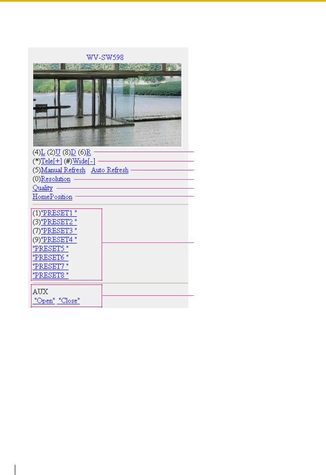
1.Access to “http://IP address/mobile”*1 or “http://Host name registered in the DDNS server/mobile” using a cellular phone.
→ Images from the camera will be displayed.
A
B
C
D
E
F
G
H
Functions |
Outline of functions |
|
|
A Pan/tilt*2 |
Controls the camera direction. The camera will pan or tilt to each direction |
|
by pressing the corresponding dial key. |
|
|
B Zooming control*2 |
It is possible to perform zooming operations of the camera by pressing “*” |
|
or “#”. |
|
|
18 Operating Instructions
|
|
2 Monitor images on a cellular phone/mobile terminal |
||
|
|
|
|
|
|
|
|
|
|
|
Functions |
Outline of functions |
|
|
|
|
|
|
|
|
C Refresh control |
Press the dial key “5” or the [Manual Refresh] button to refresh the camera |
|
|
|
|
images. |
|
|
|
|
Press the [Auto Refresh] button to refresh the images from the camera in |
|
|
|
|
5-second intervals. |
|
|
|
|
When the dial key “5” or the [Manual Refresh] button is pressed again, the |
|
|
|
|
refresh mode of the camera will return to manual refresh. |
|
|
|
|
IMPORTANT |
|
|
|
|
• Transmission will be periodically performed when “Auto Refresh” is |
|
|
|
|
selected for the camera image. Confirm the contract plan of the |
|
|
|
|
cellular phone in use before using this function. |
|
|
|
|
• Depending on the cellular phone in use, “Auto Refresh” may be |
|
|
|
|
unavailable. |
|
|
|
|
|
|
|
|
D Resolution control |
Changes the image capture size by pressing the dial key “0”. |
|
|
|
|
• Image in the aspect ratio of “4:3” |
Changes the image capture size |
|
|
|
|
between 320x240 (default) and |
|
|
|
|
640x480. |
|
|
|
• Image in the aspect ratio of |
|
|
|
|
Changes the image capture size |
|
|
|
|
“16:9” |
between 320x180 (default) and |
|
|
|
|
640x360. |
|
|
|
|
|
|
|
E Image quality |
It is possible to change the image quality between “Quality1” and |
|
|
|
control |
“Quality2”. (®page 83) |
|
|
|
|
|
|
|
|
F Home position*2 |
The camera will move to the home position (®page 91). Home position |
|
|
|
|
will be displayed only when home position is set. |
|
|
|
|
|
|
|
|
G Preset*2 |
The camera will move to the designated preset position to display images |
|
|
|
|
by pressing the dial key corresponding to the desired channel. (The dial key |
|
|
|
|
numbers are not displayed for Preset No 5 or greater. Only preset IDs will |
|
|
|
|
be displayed for them.) (®page 106) |
|
|
|
|
|
|
|
|
H AUX control*2 |
Controls the AUX terminal. |
|
|
|
|
These buttons will be displayed only when “AUX output” is selected for |
|
|
|
|
“Terminal 3” on the setup menu. (®page 130) |
|
|
|
|
|
|
|
Note
•Some cellular phones cannot change the image capture size even when resolution is changed by resolution control.
•When the HTTP port number is changed from “80”, enter “http://IP address: (colon) + port number/ mobile”*1 in the address box of the browser. When using the DDNS function, access to “http://Host name registered in the DDNS server: (colon) + port number/mobile”.
•When “HTTPS” is selected for “HTTPS” - “Connection” on the [Network] tab of the “Network” page, enter as follows.
“https://IP address: (colon) + port number/mobile” or “https://Host name registered in the DDNS server: (colon) + port number/mobile”
•When the authentication window is displayed, enter the user name of an administrator or user and password. Depending on the cellular phone in use, password entry may be required each time the screen is switched.
•It is impossible to transmit/receive audio using a cellular phone.
Operating Instructions |
19 |
|
|

2 Monitor images on a cellular phone/mobile terminal
*1
*2
•Depending on the cellular phone in use, larger size images may not be displayed. In this case, selecting “9 Low” for “Image quality setting” of “JPEG” (®page 83) may sometimes solve this problem.
•Depending on the cellular phone in use or its contract plan, it may be impossible to access.
IP address is the global WAN IP address of the router that can be accessed via the Internet.
When “User auth.” is set to “On” (®page 151), only users with the access level of “1. Administrator” or “2. Camera control” will be displayed.
2.2 Monitor images on a mobile terminal
It is possible to connect to the camera using a mobile terminal via the Internet and monitor images (MJPEG only) from the camera on the screen of the mobile terminal. Images are refreshed automatically to display the latest image.
The compatible mobile terminals are shown as follows. (As of February, 2013)
–iPad, iPhone, iPod touch (iOS 4.2.1 or later)
–Android™ mobile terminals
When an Android terminal is used, an MJPEG format image is displayed by the Firefox® browser, but a JPEG format image is displayed by the standard browser.
For further information about compatible devices, refer to our website (http://security.panasonic.com/pss/security/support/info.html).
IMPORTANT
•When the authentication window is displayed, enter the user name and password. The default user name and password are as follows.
User name: admin Password: 12345
To enhance the security, change the password for the user “admin”. (®page 151)
•When “2 mega pixel [16:9]” is selected for “Image capture mode”, the maximum image capture size is 640x360.
Note
•It is necessary to configure the network settings of the mobile terminal in advance to connect to the Internet and monitor images from the camera. (®page 161)
20 Operating Instructions
2 Monitor images on a cellular phone/mobile terminal
1.Access to “http://IP address/cam”*1 or “http://Host name registered in the DDNS server/cam”*2 using a mobile terminal.
→ Images from the camera will be displayed.
A
B
C
D
Live images area
Displays images from the camera.
Operation buttons area
When functions are selected in the function selection area D, buttons to operate those functions are displayed.
Zoom operation area
Buttons to operate the zoom are displayed.
Function selection area
Displays the functions that can be operated. When a function is selected from here it is displayed in the operation buttons area B.
Operating Instructions |
21 |
|
|
2 Monitor images on a cellular phone/mobile terminal
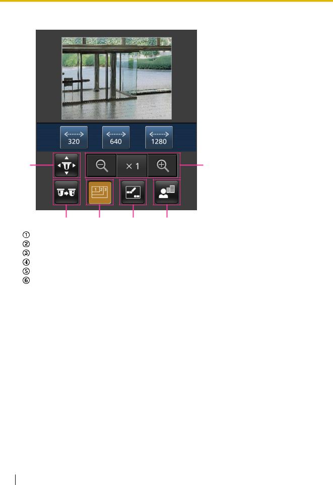
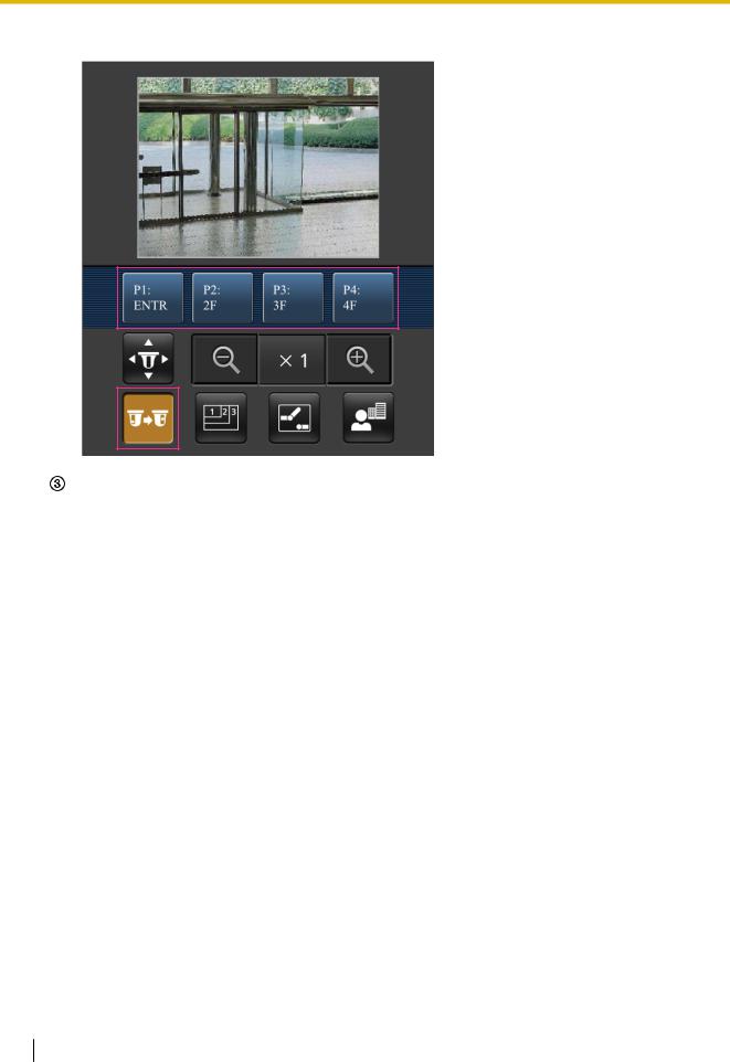
2. Click the button of the function that you want to operate.
A |
F |
B C D E
Pan/Tilt
Preset
Resolution control
AUX control
Focus display
Zoom display
Each function is explained below.
22 Operating Instructions

2 Monitor images on a cellular phone/mobile terminal
Pan/Tilt
Press the  button to display the buttons used to operate pan/tilt on the screen. The pan/tilt can be adjusted in each direction with the
  ,
,  ,
,  , and
, and  buttons.
Preset
Press the  button to display the buttons used to select the preset position on the screen. Camera
images are displayed of the registered preset camera directions according to the preset numbers selected from the buttons.
•Only position numbers 1-4 for the preset positions are displayed.
•Only registered preset positions are displayed. Unregistered preset positions are not displayed.
Operating Instructions |
23 |
|
|
2 Monitor images on a cellular phone/mobile terminal
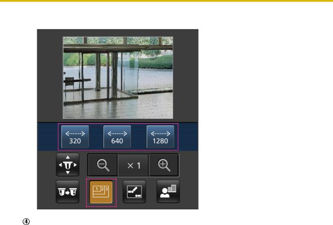
Resolution control
Press the  button to display the buttons used to select the resolution on the screen. The resolution
can be changed by selecting a resolution setting from the buttons. Image capture mode
•“2 mega pixel [16:9]” images: Changes the image capture size between 320x180 and 640x360 (default).
•“1.3 mega pixel [16:9]” images: Changes the image capture size between 320x180, 640x360 (default), and 1280x720.
•“1.3 mega pixel [4:3]” images: Changes the image capture size between 320x240, 640x480 (default), and 1280x960.
24 Operating Instructions
2 Monitor images on a cellular phone/mobile terminal
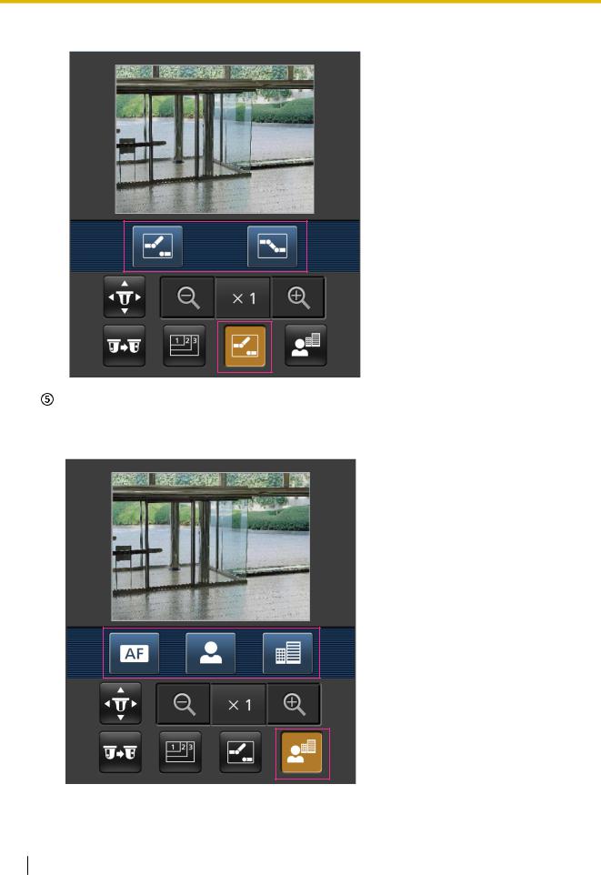
AUX control
Press the  button to display the buttons used to operate the AUX output on the screen. The AUX output terminals can be controlled with the
  and
and  buttons.
This function is only displayed when “Terminal 3” is set to “AUX output” on the settings menu. (®page 130)
Operating Instructions |
25 |
|
|
2 Monitor images on a cellular phone/mobile terminal
Focus display
Press the  button to display the buttons used to operate the focus on the screen. The camera’s focus can be operated with the
  ,
,  , and
, and  buttons.
26 Operating Instructions

2 Monitor images on a cellular phone/mobile terminal
Zoom display
The camera’s zoom can be operated with the  ,
,  , and
, and  buttons.
Note
•You can change the image size displayed on the mobile terminal by accessing the following addresses.
–Large display: http://IP address/cam/dl
–Medium display: http://IP address/cam/dm
–Small display: http://IP address/cam/ds
•When the resolution is changed by the resolution control, the displayed resolution changes but the image size remains the same.
•When the HTTP port number is changed from “80”, enter “http://IP address: (colon) + port number/ cam”*1 in the address box of the browser. When using the DDNS function, access to “http://Host name registered in the DDNS server: (colon) + port number/cam”*2.
•When “HTTPS” is selected for “HTTPS” - “Connection” on the [Network] tab of the “Network” page, enter as follows.
“https://IP address: (colon) + port number/cam” or “https://Host name registered in the DDNS server: (colon) + port number/cam”
•When the authentication window is displayed, enter the user name of an administrator or user and password. Depending on the mobile terminal in use, password entry may be required each time the screen is switched.
•It is impossible to transmit/receive audio using a mobile terminal.
•Depending on the mobile terminal in use, larger size images may not be displayed. In this case, selecting “9 Low” for “Image quality setting” of “JPEG” (®page 83) may sometimes solve this problem.
•Depending on the mobile terminal in use or its contract plan, it may be impossible to access.
*1
*2
IP address is the global WAN IP address of the router that can be accessed via the Internet. However, when accessing the same LAN as the camera with a wireless compatible mobile terminal, the IP address is the local IP address.
Only when accessing the camera via the Internet.
Operating Instructions |
27 |
|
|
3 Record images on the SD memory card manually
3 Record images on the SD memory card manually
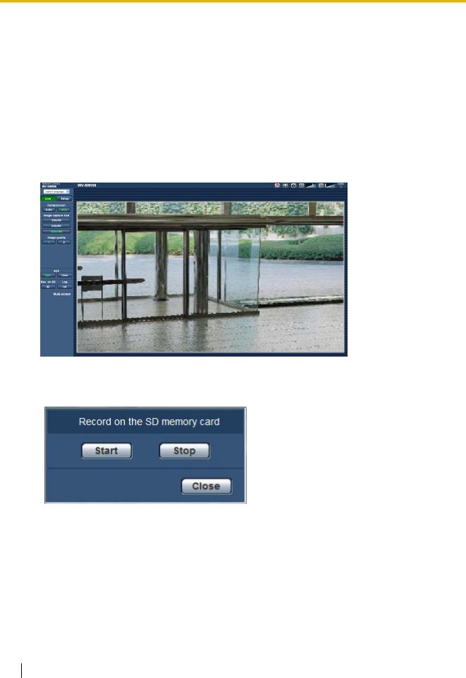
Images displayed on the “Live” page can be recorded on the SD memory card manually. This button is operable only when “Manual” is selected for “Save trigger” on the [SD memory card] tab on the “Basic” page of the setup menu. (®page 62)
It is possible to select “JPEG”, “H.264(1)”, or “H.264(2)” on “Recording format” of the setup menu. (®page 61) When “JPEG” is selected for “Recording format”, still image data are recorded. When “H. 264(1)” or “H.264(2)” is selected, video data are recorded.
Images recorded on the SD memory card can be copied onto the PC. (®page 68) 1. Display the “Live” page. (®page 7)
2.Click the [SD] button.
→ The SD recording window will open.
3.Click the [Start] button to start recording images on the SD memory card. The SD recording status indicator will light red (®page 9) while images are being recorded on the SD memory card.
The image saving interval can be configured on the [SD memory card] tab of the “Basic” page. (®page 59)
4.Click the [Stop] button to stop saving images on the SD memory card. ® The SD recording status indicator will turn off.
5.Click the [Close] button to close the window.
28 Operating Instructions

3 Record images on the SD memory card manually
Note
•Image data saved on Drive B can be obtained by executing “Access img.” on the [SD memory card] tab and logging in from the user authentication window (®page 68).
The destination to save image data is a fixed directory on Drive B. (®page 225)
•When the [Start] button is clicked immediately after the [Stop] button is clicked, saving of images may not start. In this case, click the [Start] button again.
Operating Instructions |
29 |
|
|

4 Action at an alarm occurrence
4 Action at an alarm occurrence
The alarm action (camera action at an alarm occurrence) will be performed when the following alarms occur.
4.1 Alarm type
• Terminal alarm: When connecting an alarm device such as a sensor to the alarm input terminal of the camera, the alarm action will be performed when the connected alarm device is activated.
• VMD alarm: When motion is detected in the set VMD area, the alarm action will be performed. *VMD stands for “Video Motion Detection”.
• Command alarm: When a Panasonic alarm protocol is received from the connected device via a network, the alarm action will be performed.
• Auto track alarm: According to the conditions set in advance, the alarm action will be performed in the auto tracking operations.
• Audio detection alarm: When the configured audio detection level is exceeded, the alarm action will be performed.
4.2 Action at an alarm occurrence
Display the alarm occurrence indication button on the “Live” page
The alarm occurrence indication button will be displayed on the “Live” page at an alarm occurrence. (®page 9)
IMPORTANT
•When “Polling(30s)” is selected for “Alarm status update mode” (®page 53), the Alarm occurrence indication button will be refreshed in 30-second intervals. For this reason, it may take a maximum of 30 seconds until the alarm occurrence indication button is displayed on the “Live” page at an alarm occurrence.
Notify of alarm occurrences to the device connected to the alarm connector
It is possible to output signals from the alarm output terminal of the camera and sound the buzzer when an alarm occurs. The settings for the alarm output can be configured in the “Alarm output terminal setup” section of the [Alarm] tab of the “Alarm” page. (®page 137)
Save images on the SD memory card
When an alarm occurs, images (JPEG/H.264) will be saved on the SD memory card. The settings to save images on the SD memory card can be configured on the [SD memory card] tab (®page 59) of the “Basic” page and the [Alarm] tab of the “Alarm” page. (®page 134)
Transmit an image onto a server automatically
An alarm image can be transmitted at an alarm occurrence to the server designated in advance. The settings required to transmit an alarm image to a server can be configured in the “Alarm image” section on the [Alarm] tab of the “Alarm” page (®page 134) and the [FTP] tab of the “Server” page (®page 157).
30 Operating Instructions
Loading...