


Panasonic TH-42PA30M, TH-50PV30M, TH-50PV30H, TH-42PA30H, TH-37PA30H User Manual
...N
1 2 3
4 5 6
7 8 9
C 0
Operating Instructions
Progressive Plasma Television
Model No. TH-37PA30
TH-42PA30
High Definition Plasma Television
Model No. TH-50PV30
Pedestal stand shown above is optional extra.
The illustration shown is an image.
Please read these instructions before operating your set and retain them for future reference.
English
TQBC0868

Dear Panasonic Customer
Welcome to the Panasonic family of customers. We hope that you will have many years of enjoyment from your new Plasma TV.
To obtain maximum benefit from your set, please read these Instructions before making any adjustments, and retain them for future reference.
Retain your purchase receipt also, and note down the model number and serial number of your set in the space provided on the rear cover of these instructions.
Contents
Important Safety Notice .............................................. |
3 |
Safety Precautions ..................................................... |
4 |
Maintenance ............................................................... |
5 |
Accessories ................................................................ |
6 |
Fitting remote control batteries ................................... |
6 |
How to open the front cover ....................................... |
7 |
Terminal cover open and close .................................. |
7 |
Fastening method ...................................................... |
7 |
Antenna connection ................................................... |
8 |
Connections ............................................................... |
9 |
How to connect the Headphones / AV3 terminals ..... |
9 |
How to connect the Monitor Output terminals |
|
to other Equipment ............................................. |
10 |
How to connect the AV1 Input terminals ............... |
10 |
How to connect the Component Input terminals ... |
10 |
How to connect the PC Input terminals ................. |
11 |
Power On / Off ......................................................... |
12 |
Basic controls: front panel and remote control ......... |
13 |
Using the On Screen Displays ................................. |
14 |
LANGUAGE ............................................................. |
14 |
Tuning ...................................................................... |
15 |
TUNING MENU ..................................................... |
15 |
Channel Selection ................................................. |
16 |
AUTO TUNE ......................................................... |
17 |
AUTO TUNE (via front panel) ............................... |
17 |
MANUAL TUNE .................................................... |
18 |
MANUAL TUNE (via front panel) .......................... |
18 |
Channel Allocation ................................................... |
19 |
PICTURE ................................................................. |
20 |
SOUND .................................................................... |
21 |
SETUP ..................................................................... |
22 |
Owner ID .................................................................. |
23 |
Aspect Controls ........................................................ |
24 |
Multi window ............................................................. |
25 |
Still ........................................................................... |
26 |
Channel search ........................................................ |
26 |
Picture and text ........................................................ |
26 |
PC mode .................................................................. |
27 |
Photo View mode ..................................................... |
29 |
Teletext operation ..................................................... |
33 |
Stereo / Bilingual Sound Selection ........................... |
35 |
VCR / DVD operation ............................................... |
36 |
Remote control setting ............................................. |
36 |
Troubleshooting ....................................................... |
37 |
Input signal can be displayed ................................... |
38 |
Specifications ........................................................... |
39 |
2

Important Safety Notice
WARNING
1)To prevent damage which may result in fire or shock hazard, do not expose this appliance to dripping or splashing.
Do not place containers with water (flower vase, cups, cosmetics, etc.) above the set. (including on shelves above, etc.)
No naked flame sources, such as lighted candles, should be placed on / above the set.
2)To prevent electric shock, do not remove cover. No user serviceable parts inside. Refer servicing to qualified service personnel.
3)Do not remove the earthing pin on the power plug. This apparatus is equipped with a three pin earthing-type power plug. This plug will only fit an earthing-type power outlet. This is a safety feature. If you are unable to insert the plug into the outlet, contact an electrician.
Do not defeat the purpose of the earthing plug.
CAUTION
1)This appliance is intended for use in environments which are relatively free of electromagnetic fields.
Using this appliance near sources of strong electromagnetic fields or where electrical noise may overlap with the input signals could cause the picture and sound to wobble or cause interference such as noise to appear. To avoid the possibility of harm to this appliance, keep it away from sources of strong electromagnetic fields.
2)If a static electricity discharge occurs inside the front cover, the screen may momentarily flicker. This is not a malfunction.
The screen will return to normality in a short while.
3)This appliance is intended for use in tropical climates.
To prevent electric shock, ensure the earthing pin on the AC supply power plug is securely connected.
Trademark Credits
•VGA is a trademark of International Business Machines Corporation.
•Macintosh is a registered trademark of Apple Computer, USA.
•S-VGA is a registered trademark of the Video Electronics Standard Association.
Even if no special notation has been made of company or product trademarks, these trademarks have been fully respected.
•SD Logo is a trademark.
CAUTION:
Symptoms |
Check |
Do not allow a still picture to be displayed for an extended period, as this can
After-images appear
cause a permanent after-image to remain on the Plasma TV.
Examples of still pictures include logos, video games, computer images, teletext and images displayed in 4:3 mode.
Without signals and operations for 2 minutes, the level of the contrast decreases automatically to prevent image retention.
Note:
The permanent after-image on the Plasma TV resulting from fixed image use is not an operating defect and as such is not covered by the Warranty.
This product is not designed to display fixed images for extended periods of time.
3

Safety Precautions
 WARNING
 Setup
Setup
This Plasma TV is for use only with the following optional accessories. Use with any other type of optional accessories may cause instability which could result in the possibility of injury.
(All of the following accessories are manufactured by Matsushita Electric Industrial Co., Ltd.)
• Pedestal ······································· TY-ST42PX20 (TH-37PA30, TH-42PA30) TY-ST50PX20 (TH-50PV30)
• Display stand ································ TY-DP4201W TY-S37PX20W (TH-37PA30) TY-S42PX20W (TH-42PA30) TY-S50PX20W (TH-50PV30)
•Wall-hanging bracket (vertical) ···· TY-WK42PV3W
•Wall-hanging bracket (angle) ······· TY-WK42PR2W
Always be sure to ask a qualified technician to carry out set-up.
Do not place the Plasma TV on sloped or unstable surfaces.
• The Plasma TV may fall off or tip over.
Do not place any objects on top of the Plasma TV.
•If water is spilt onto the Plasma TV or foreign objects get inside it, a short-circuit may occur which could result in fire or electric shock. If any foreign objects get inside the Plasma TV, please consult your local Panasonic dealer.
For sufficient ventilation;
If using the pedestal (optional accessory) for the Plasma TV, leave a space of at least 10 cm at the top, left and right, at least 6 cm at the bottom, and at least 7 cm at the rear. If using some other setting-up method, leave a space of at least 10 cm at the top, bottom, left and right, and at least 1.9 cm at the rear.
Avoid installing this product near electronic equipment that is easy to receive electromagnetic waves.
• It will cause interference in image, sound, etc. In particular, keep video equipment away from this product.
 When using the Plasma TV
The Plasma TV is designed to operate on 220 - 240 V AC, 50/60 Hz.
Do not cover the ventilation holes.
• Doing so may cause the Plasma TV to overheat, which can cause fire or damage to the Plasma TV.
Do not stick any foreign objects into the Plasma TV.
•Do not insert any metal or flammable objects into the ventilations holes or drop them onto the Plasma TV, as doing so can cause fire or electric shock.
Do not remove the cover or modify it in any way.
•High voltages which can cause severe electric shocks are present inside the Plasma TV. For any inspection, adjustment and repair work, please contact your local Panasonic dealer.
Securely insert the power supply plug as far as it will go.
•If the plug is not fully inserted, heat may be generated which could cause fire. If the plug is damaged or the wall socket is loose, they shall not be used.
Do not handle the power supply plug with wet hands.
• Doing so may cause electric shocks.
Do not do anything that may damage the power cable. When disconnecting the power cable, pull on the plug body, not the cable.
•Do not damage the cable, make any modifications to it, place heavy objects on top of it, heat it, place it near any hot objects, twist it, bend it excessively or pull it. To do so may cause fire and electric shock. If the power cable is damaged, have it repaired at your local Panasonic dealer.
If the Plasma TV is not going to be used for any prolonged length of time, unplug the power supply plug from the wall outlet.
4

Safety Precautions
 If problems occur during use
If a problem occurs (such as no picture or no sound), or if smoke or an abnormal odour starts to come out from the Plasma TV, immediately unplug the power supply plug from the wall outlet.
•If you continue to use the Plasma TV in this condition, fire or electric shock could result. After checking that the smoke has stopped, contact your local Panasonic dealer so that the necessary repairs can be made. Repairing the Plasma TV yourself is extremely dangerous, and should never be attempted.
If water or foreign objects get inside the Plasma TV, if the Plasma TV is dropped, or if the cabinet becomes damages, disconnect the power supply plug immediately.
•A short circuit may occur, which could cause fire. Contact your local Panasonic dealer for any repairs that need to be made.

 CAUTION
 When using the Plasma TV
Do not bring your hands, face or objects close to the ventilation holes of the Plasma TV.
•Heated air comes out from the ventilation holes at the top of Plasma TV will be hot. Do not bring your hands or face, or objects which cannot withstand heat, close to this port, otherwise burns or deformation could result.
Be sure to disconnect all cables before moving the Plasma TV.
•If the Plasma TV is moved while some of the cables are still connected, the cables may become damaged, and fire or electric shock could result.
Disconnect the power supply plug from the wall socket as a safety precaution before carrying out any cleaning.
• Electric shocks can result if this is not done.
Clean the power cable regularly to prevent it becoming dusty.
•If dust built up on the power cord plug, the resultant humidity can damage the insulation, which could result in fire. Pull the power cord plug out from the wall outlet and wipe the mains lead with a dry cloth.
This Plasma TV radiates infrared rays, therefore it may affect other infrared communication equipment.
Install your infrared sensor in a place away from direct or reflected light from your Plasma TV.
Maintenance
The front of the display panel has been specially treated. Wipe the panel surface gently using only a cleaning cloth or a soft, lint-free cloth.
•If the surface is particularly dirty, wipe with a soft, lint-free cloth which has been soaked in pure water or water to which a small amount of neutral detergent has been added, and then wipe it evenly with a dry cloth of the same type until the surface is dry.
•Do not scratch or hit the surface of the panel with fingernails or other hard objects, otherwise the surface may become damaged. Furthermore, avoid contact with volatile substances such as insect sprays, solvents and thinner, otherwise the quality of the surface may be adversely affected.
If the cabinet becomes dirty, wipe it with a soft, dry cloth.
•If the cabinet is particularly dirty, soak the cloth in water to which a small amount of neutral detergent has been added and then wring the cloth dry. Use this cloth to wipe the cabinet, and then wipe it dry with a dry cloth.
•Do not allow any detergent to come into direct contact with the surface of the Plasma TV.
If water droplets get inside the unit, operating problems may result.
•Avoid contact with volatile substances such as insect sprays, solvents and thinner, otherwise the quality of the cabinet surface may be adversely affected or the coating may peel off. Furthermore, do not leave it for long periods in contact with articles made from rubber or PVC.
5

Accessories
Check that you have the accessories and items shown
Operating Instruction book |
Remote Control |
Power Cable |
|
Transmitter |
|
|
(EUR7635040) |
|
N
1 |
2 |
3 |
4 |
5 |
6 |
7 |
8 |
9 |
C |
0 |
|
|
|
|
(Only for Middle East area) |
Batteries for the Remote |
Ferrite core |
Ferrite core |
Clamper × 2 |
Control Transmitter |
(Small size) × 5 |
(Large size) |
× 3 |
(2 × R6 (AA) size) |
|
|
|
Installing the ferrite core (Small size) Installing the ferrite core (Large size)
1 |
2 |
3 |
|
1 |
2 |
3 |
|
|
Open |
|
|
|
Open |
|
|
|
|
|
|
|
|
Pull back the tabs. |
|
Press the cable |
Pull back the tabs. |
|
Press the cable |
|
(in two places) |
|
through and close. |
(in two places) |
|
through and close. |
Fitting remote control batteries
1 |
2 |
|
3 |
|
|
+ |
|
|
|
- |
|
|
|
+ |
|
|
|
- |
|
|
|
“R6 (AA)” size |
|
|
Pull and hold the hook, then |
Insert batteries - note correct |
Replace the cover. |
|
open the battery cover. |
polarity ( + and -). |
|
Do not use rechargeable (Ni-Cad) batteries.
They are different in shape and performance and may fail to ensure correct operation.
Dispose batteries in an environment-friendly manner.
 Battery cautions
The incorrect use of batteries can cause electrolyte leakage which will corrode the Remote Control or cause the batteries to burst.
Observe the following precaution:
1.Batteries shall always be replaced as a pair. Always use new batteries when replacing the old set.
2.Do not combine a used battery with a new one.
3.Do not mix battery types (example:“Zinc Carbon” with “Alkaline”).
4.Do not attempt to charge, short-circuit, disassemble, heat or burn used batteries.
5.Battery replacement is necessary when remote control acts sporadically or stops operating the TV set.
6

How to open the front cover
SD CARDT
PUSH-EJEC
Push “ ”.
”.
Terminal cover open and close
Open
1. Push down hooks and pull the
2 1
cover slightly towards yourself to disengage the claws (at 4 points).
2. Slowly pull out in the downward direction.
Close
1
1. |
Insert the claws (at 4 points) |
2 |
at the bottom end. |
|
|
1 2. |
Push until it clicks. |
When connecting to the rear AV Input / Output terminals, connect through this window. (This window cannot close completely when connecting the cables.)
Other cables should be connected before closing the terminal cover.
Fastening method
Clamper |
Open |
Close |
Fastening of Power Cable and other cables
1 |
1 2 |
Fastening method of other cables |
Attach the clamper on the installation hole, and fasten them.
Bundle the cable with the cable fastening clamper.
Fastening band
2
Fastening method of Power Cable
1.Insert the power plug into the main body.
2.Fasten with the Power Cable fastening band.
Fastening |
Loosening |
2 Pull off.
Keep the knob
To tighten.  pressed.
1
7
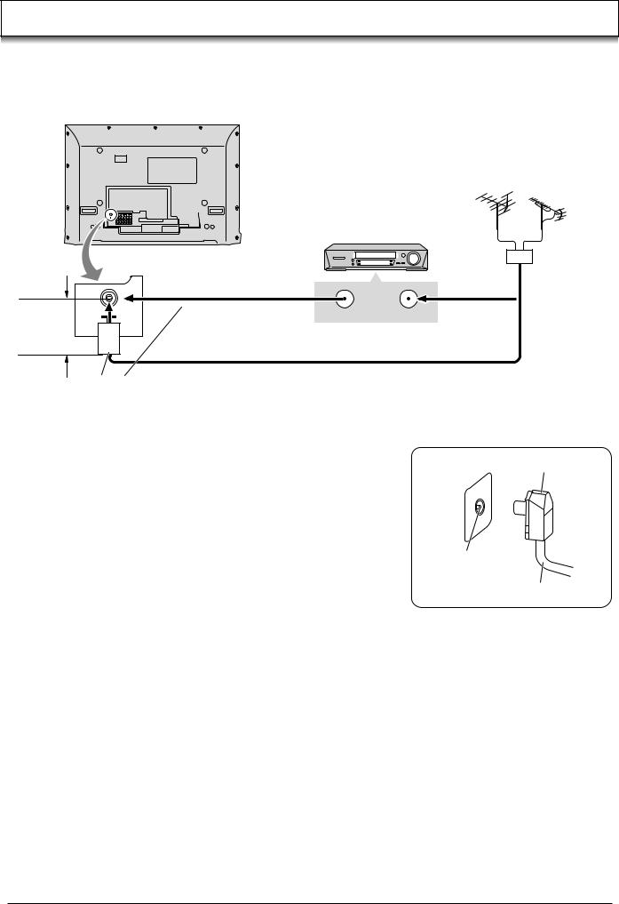
Antenna connection
For proper reception of VHF / UHF channels, an external antenna is required. For best reception, an outdoor antenna is recommended.
VHF Aerial UHF Aerial
VCR
Mixer
|
ANT OUTPUT ANT INPUT |
OR |
|
Less than 10 cm
75 Ω Coaxial cable
Ferrite core (Large size) (supplied)
Notes: |
|
|
• Do not put the Coaxial cable close to the Power cable to avoid noise. |
Coaxial Aerial plug |
|
• Do not place the Coaxial cable under the TV. |
||
|
||
• Additional equipment, cables and adapter plugs shown are not supplied |
|
|
with this TV set. |
|
|
• To obtain optimum quality picture and sound, an Aerial, the correct cable |
|
|
(75 Ω coaxial) and the correct terminating plug are required. |
|
|
• If a communal Aerial system is used, you may require the correct |
|
|
connection cable and plug between the wall Aerial socket and your TV. |
RF in |
|
• Your local Television Service Centre or Dealer may be able to assist you |
terminal |
|
in obtaining the correct Aerial system for your particular area and the |
75 Ω Coaxial cable |
|
accessories required. |
|
•Any matters regarding Aerial installation, upgrading of existing systems or accessories required, and the costs incurred, are the responsibility of you, the Customer.
8

Connections
It is possible to connect a variety of additional equipment to this TV. The following pages detail how to connect external equipment to the front and rear of the TV.
Once your equipment is connected, use the following procedure to view the input:
Press the TV/AV button. |
TV/AV |
|
|
||
Whilst the on screen selector keys are displayed, press coloured |
|
|
buttons to select the AV source you wish to view. |
|
|
Red button |
: AV1 Audio, Video, S-Video terminals |
|
Green button |
: AV2 Audio, Video / Component terminals |
|
Yellow button |
: AV3 Audio, Video, S-Video / PC terminals |
|
Blue button |
: AV4 Audio, Video / Component terminals |
|
The on screen selector keys that appear clear after a few seconds. If you want to select an input when the keys are not shown, press any coloured button and the keys will reappear.
Notes:
•You can also select an AV source using the TV/AV button on the front panel of the TV.
Press the TV/AV button repeatedly until you reach the AV source you wish to view.
•When a Monaural VCR is used, connect the Monaural Audio cable to the AUDIO L terminal.
•Additional equipment and cables shown are not supplied with this TV set.
OK
N
1 2 3
4 5 6
7 8 9
C 0
TV
How to connect the Headphones / AV3 terminals
S-VIDEO 4 pin terminal
Chrominance in |
Luminance in |
|
Chrominance earth |
Luminance earth |
Headphones |
|
|
|
|
|
(Optional) |
Example of input signal source
VCR
S-VIDEO VCR
DVD PLAYER
S-VIDEO
OUT
CAMCORDER |
VIDEO |
|
OUT |
AUDIO
OUT
Less than
 10 cm
10 cm
M3 plug
Ferrite core (Small size) (supplied)
Connect the S-VIDEO
or VIDEO terminal. Less than
 10 cm
10 cm
S-VIDEO
VIDEO
L
AUDIO
R
S VIDEO VIDEO |
L |
R |
AV3 |
|
|
Note:
The volume level of the headphones can be adjusted by selecting “HEADPHONE VOL.” from the SOUND menu.
9

Connections
How to connect the Monitor Output terminals to other Equipment
Example of output signal source
VCR
MONITOR
VIDEO
IN
L
AUDIO
IN R
Amplifier to speaker system
MONITOR
OUT
AV1 |
IN |
AV2 |
IN |
AV4 |
IN |
S-VIDEO |
COMPONENT |
COMPONENT |
|||
|
|
|
|
||
MONITOR |
OUT |
|
Y |
|
Y |
|
|
|
|
||
VIDEO |
|
|
|
|
|
|
MONO |
MONO |
PB |
MONO |
PB |
L |
|
|
|
|
|
AUDIO |
|
|
PR |
|
PR |
R |
|
|
|
|
|
How to connect the AV1 Input terminals
Example of input signal source
VCR
S-VIDEO VCR
DVD PLAYER
CAMCORDER
Connect the S-VIDEO or VIDEO terminal.
S-VIDEO
OUT
|
|
|
AV1 IN |
AV2 |
IN |
AV4 |
IN |
|
|
|
S-VIDEO |
COMPONENT |
COMPONENT |
||
VIDEO |
|
|
|
|
|
|
|
|
|
MONITOR OUT |
|
Y |
|
Y |
|
OUT |
|
|
|
|
|
||
|
MONO |
VIDEO |
|
|
|
|
|
|
L |
|
|
|
|
||
|
|
MONO |
MONO |
PB |
MONO |
PB |
|
|
|
|
|||||
AUDIO |
|
|
L |
|
|
|
|
|
|
AUDIO |
|
|
|
|
|
OUT |
R |
|
|
PR |
|
PR |
|
|
|
|
|
|
|
||
R
AV1 IN
How to connect the Component Input terminals
Example of input signal source |
COMPONENT VIDEO OUT |
||
|
|
|
Y |
DVD PLAYER |
Y, PB, PR, |
PB |
|
|
|||
|
OUT |
|
|
|
|
|
|
|
|
|
PR |
Digital TV-SET-TOP-BOX |
|
VIDEO |
|
(DTV-STB) |
|
|
|
|
OUT |
|
|
|
|
|
L |
|
|
AUDIO |
R |
|
|
OUT |
|
|
|
|
|
Connect the VIDEO or COMPONENT
VIDEO terminal.
AV1 |
IN |
AV2 |
IN |
AV4 |
IN |
Y |
|
COMPONENT |
COMPONENT |
||
S-VIDEO |
|
|
|
|
|
MONITOR |
OUT |
|
Y |
|
Y |
|
|
|
|
||
VIDEO |
|
|
|
|
|
MONO PB/CB |
|
|
|
|
|
|
MONO |
MONO |
PB |
MONO |
PB |
L |
|
|
|
|
|
AUDIO |
|
|
PR |
|
PR |
PR/CR |
|
|
|
|
|
R
AV2 / 4 IN
Note:
Component input terminals are used for 525i / p, 625i / p, 1125i / 50 Hz, 1125i / 60 Hz or SMPTE295M standard 1250i signal.
10
Connections
How to connect the PC Input terminals
COMPUTER
S VIDEO VIDEO L |
R |
PC |
AV3 |
|
|
Ferrite core (Small size) |
Less than |
|
10 cm |
||
(supplied) |
||
|
||
AUDIO |
|
Stereo plug
Connect a cable which matches the audio output terminal on the computer.
Conversion adapter |
Less than |
Less than |
(if necessary) |
10 cm |
10 cm |
|
|
RGB |
|
|
PC cable |
D-sub 15p
Ferrite core (Large size) (supplied)
Notes:
•Computer signals which can be input are those with a horizontal scanning frequency of 15 to 110 kHz and vertical scanning frequency of 48 to 120 Hz. (However, the image will not be displayed properly if the signals exceed 1,200 lines.)
•The display resolution is a maximum of 640 × 480 dots (TH-37PA30, TH-42PA30), 1,024 × 768 dots (TH-50PV30) when the aspect mode is set to “4:3”, and 852 × 480 dots (TH-37PA30, TH-42PA30), 1,366 × 768 dots (TH-50PV30) when the aspect mode is set to “16:9”. If the display resolution exceeds these maximums, it may not be possible to show fine detail with sufficient clarity.
•Some PC models cannot be connected to the set.
•There is no need to use an adapter for computers with DOS/V compatible D-sub 15P terminal.
•The computer shown in the illustration is for example purposes only.
•Additional equipment and cables shown are not supplied with this set.
•Do not set the horizontal and vertical scanning frequencies for PC signals which are above or below the specified frequency range.
Signal Names for D-sub 15P Connector
5 |
|
4 |
3 |
2 |
|
1 |
10 |
9 |
|
8 |
7 |
6 |
|
15 |
14 |
13 |
12 |
|
11 |
|
Pin Layout for PC Input Terminal
Pin No. |
Signal Name |
Pin No. |
Signal Name |
Pin No. |
Signal Name |
1 |
R |
6 |
GND (Ground) |
11 |
NC (not connected) |
2 |
G |
7 |
GND (Ground) |
12 |
NC |
3 |
B |
8 |
GND (Ground) |
13 |
HD/SYNC |
4 |
NC |
9 |
NC (not connected) |
14 |
VD |
5 |
GND (Ground) |
10 |
GND (Ground) |
15 |
NC |
11
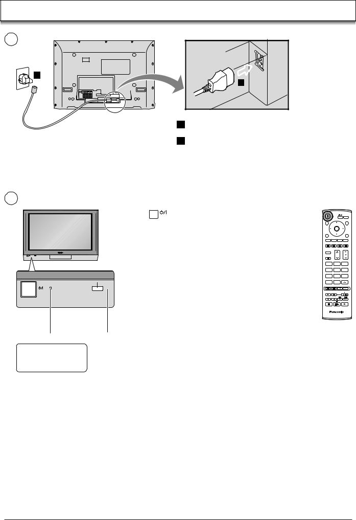
Power On / Off
1
2 


 1
1
1 Connect the mains lead to the Plasma TV.
2 Connect the mains plug to the wall socket.
2
 Remote control
  signal sensor
Press the  switch on the TV set to turn the set on.
Owner ID setting screen is displayed. See page 23.
To switch the TV set to Standby mode, press the  button on the remote control.
The TV set can be switched on by pressing the  button again if it was switched to Standby mode.
Note:
This TV will still consume some power as long as the mains plug is still inserted into the wall socket.
Power Indicator |
C.A.T.S. sensor |
||
LED Indicator |
Plasma C.A.T.S. (Contrast Automatic Tracking System) |
||
Plasma C.A.T.S. automatically senses the ambient light conditions and |
|||
Standby |
: Red |
||
adjusts the brightness and gradation accordingly, to optimise contrast. |
|||
On |
: No Light |
||
(Effective when Viewing mode is set to Auto.) |
|||
|
|
||
OK
N
1 2 3
4 5 6
7 8 9
C 0
TV
12
 Loading...