


SC-AK48

RQT5321-B
CD Stereo System
Operating Instructions
Model No. SC-AK48
Note:
The “EB” indication shown on the packing case
indicates United Kingdom.
Before connecting, operating or adjusting this pro-
duct, please read these instructions completely.
Please keep this manual for future reference.
EB

2
Before using
RQT5321
(Back of product)
Dear customer
Thank you for purchasing this product.
For optimum performance and safety, please read these instructions
carefully.
These operating instructions are applicable to the following system.
System SC-AK48
Main unit SA-AK48
Speakers SB-AK48
AC mains lead (RJA0053-2X) ...................... 1 pc.
Remote control transmitter
(RAK-SC957WK)........................................... 1 pc.
Batteries for remote control...................... 2 pcs.
FM indoor antenna (RSA0007) .................... 1 pc.
AM loop antenna (RSA0029) ....................... 1 pc.
Antenna plug adaptor (SJP9009)................ 1 pc.
Supplied accessories
Please check and identify the
supplied accessories.
CAUTION!
THIS PRODUCT UTILIZES A LASER.
USE OF CONTROLS OR ADJUSTMENTS OR PERFORMANCE
OF PROCEDURES OTHER THAN THOSE SPECIFIED HEREIN
MAY RESULT IN HAZARDOUS RADIATION EXPOSURE.
DO NOT OPEN COVERS AND DO NOT REPAIR YOURSELF.
REFER SERVICING TO QUALIFIED PERSONNEL.
CAUTION!
DO NOT INSTALL OR PLACE THIS UNIT IN A BOOKCASE,
BUILT IN CABINET OR IN ANOTHER CONFINED SPACE.
ENSURE THE UNIT IS WELL VENTILATED. ENSURE THAT CUR-
TAINS AND ANY OTHER MATERIALS DO NOT OBSTRUCT THE
VENTILATION TO PREVENT RISK OF ELECTRIC SHOCK OR
FIRE HAZARD DUE TO OVERHEATING.
Use numbers indicated in parentheses when asking for replacement
parts.

3
Before using
RQT5321
Table of contents
Before using
Supplied accessories .................................................................... 2
Safety precautions.........................................................................3
Caution for AC Mains Lead .......................................................... 4
Concerning the remote control .................................................... 5
Battery installation ......................................................................5
Correct method of use ................................................................5
Placement of speakers.................................................................. 5
Connections ................................................................................... 6
Basic connections (for supplied accessories) ............................. 6
Optional antenna connections .................................................... 7
External unit connection .............................................................7
Front panel controls ...................................................................... 8
Turning the demo function off ..................................................... 9
ECO mode ...................................................................................... 9
Auto-off function ......................................................................... 10
Setting the time ........................................................................... 10
Radio operations
Presetting radio broadcasts ....................................................... 11
Listening to radio broadcasts .................................................... 12
Compact disc operations
Concerning CDs ..........................................................................13
Listening to compact discs ........................................................ 14
Direct access play ....................................................................15
Repeat play .............................................................................. 15
Random play ............................................................................ 15
Program play ............................................................................ 16
To listen to special CDs and tracks (CD Manager function) ..... 17
Cassette deck operations
Listening to tapes........................................................................ 18
Concerning cassette tapes ......................................................... 19
Recording operations
Before recording (Deck 2 only) ..................................................20
Tape-to-tape recording................................................................ 20
Recording from radio broadcasts .............................................. 21
Recording from compact discs .................................................. 22
To record special CDs and tracks (CD Manager function)........ 23
Sound quality/sound field operations
Using the built-in sound quality/sound field settings............... 24
Boosting the super woofer ......................................................... 24
Varying the sound quality with the manual equalizer .............. 25
Varying the sound quality with the acoustic image
(Al) equalizer ............................................................................. 25
Selecting the TRI-AMP mode...................................................... 26
Timer operations
Using the timer ............................................................................ 26
Using the sleep timer................................................................ 26
Using the play/record timer ....................................................... 27
Reference
Convenient functions .................................................................. 29
Using an external unit .................................................................29
Troubleshooting guide ................................................................30
Maintenance ................................................................................. 31
Technical specifications .............................................. Back cover
Safety precautions
Placement
Set the system up on an even surface away from direct sunlight,
high temperatures, high humidity, and excessive vibration. These
conditions can damage the cabinet and other components, thereby
shortening the unit’s service life.
Place it at least 15 cm away from wall surfaces to avoid distortion
and unwanted acoustical effects.
Do not place heavy items on the unit.
Voltage
Do not use high voltage power sources. This can overload the unit
and cause a fire.
Do not use a DC power source. Check the source carefully when
setting the unit up on a ship or other place where DC is used.
AC mains lead protection
Ensure the AC mains lead is connected correctly and not damaged.
Poor connection and lead damage can cause fire or electric shock.
Do not pull, bend, or place heavy items on the lead.
Grasp the plug firmly when unplugging the lead. Pulling the AC
mains lead can cause electric shock.
Do not handle the plug with wet hands. This can cause electric
shock.
Foreign matter
Do not let metal objects fall inside the unit. This can cause electric
shock or malfunction.
Do not let liquids get into the unit. This can cause electric shock or
malfunction. If this occurs, immediately disconnect the unit from the
power supply and contact your dealer.
Do not spray insecticides onto or into the unit. They contain
flammable gases which can ignite if sprayed into the unit.
Service
Do not attempt to repair this unit by yourself. If sound is interrupted,
indicators fail to light, smoke appears, or any other problem that is not
covered in these instructions occurs, disconnect the AC mains lead
and contact your dealer or an authorized service center. Electric shock
or damage to the unit can occur if the unit is repaired, disassembled
or reconstructed by unqualified persons.
Extend operating life by disconnecting the unit from the power source
if it is not to be used for a long time.
4
Before using
RQT5321
Caution for AC Mains Lead
WARNING: DO NOT CONNECT EITHER WIRE TO
THE EARTH TERMINAL WHICH IS MARKED WITH
THE LETTER E, BY THE EARTH SYMBOL i
OR
COLOURED GREEN OR GREEN/YELLOW.
THIS PLUG IS NOT WATERPROOF—KEEP DRY.
Before use
Remove the connector cover.
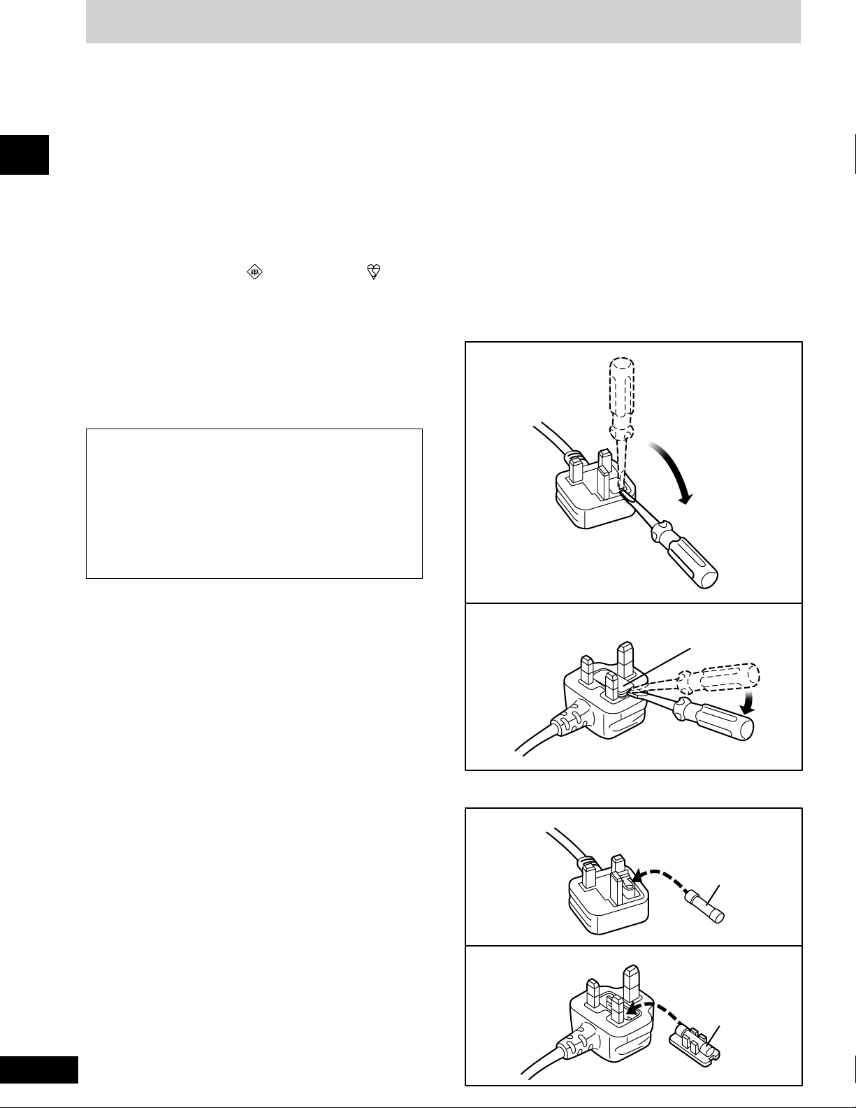
How to replace the fuse
The location of the fuse differ according to the type of
AC mains plug (figures A and B). Confirm the AC mains
plug fitted and follow the instructions below.
Illustrations may differ from actual AC mains plug.
(For United Kingdom)
(“EB” area code model only)
For your safety, please read the following text carefully.
This appliance is supplied with a moulded three pin
mains plug for your safety and convenience.
A 5-ampere fuse is fitted in this plug.
Should the fuse need to be replaced please ensure that
the replacement fuse has a rating of 5-ampere and that
it is approved by ASTA or BSI to BS1362.
Check for the ASTA mark or the BSI mark on the
body of the fuse.
If the plug contains a removable fuse cover you must
ensure that it is refitted when the fuse is replaced.
If you lose the fuse cover the plug must not be used
until a replacement cover is obtained.
A replacement fuse cover can be purchased from your
local dealer.
CAUTION!
IF THE FITTED MOULDED PLUG IS UNSUITABLE
FOR THE SOCKET OUTLET IN YOUR HOME THEN
THE FUSE SHOULD BE REMOVED AND THE PLUG
CUT OFF AND DISPOSED OF SAFELY.
THERE IS A DANGER OF SEVERE ELECTRICAL
SHOCK IF THE CUT OFF PLUG IS INSERTED INTO
ANY 13-AMPERE SOCKET.
If a new plug is to be fitted please observe the wiring
code as stated below.
If in any doubt please consult a qualified electrician.
IMPORTANT
The wires in this mains lead are coloured in accordance
with the following code:
Blue: Neutral, Brown: Live.
As these colours may not correspond with the coloured
markings identifying the terminals in your plug, proceed
as follows:
The wire which is coloured Blue must be connected to
the terminal which is marked with the letter N or coloured
Black or Blue.
The wire which is coloured Brown must be connected to
the terminal which is marked with the letter L or coloured
Brown or Red.
Figure A
Figure B
Figure A
Figure B
Fuse
(5 ampere)
Fuse
(5 ampere)
2. Replace the fuse and close or attach the fuse cover.
Fuse cover
1. Open the fuse cover with a screwdriver.

5
Before using
RQT5321
B
C
A
R6, AA, UM-3
30°
30°
Concerning the remote control
Remote control
signal sensor
About 7 meters in front of
the signal sensor
Insert the batteries observing the correct polarities (e, d).
Transmission
window
A
B
Super woofer
Battery installation
Use of batteries
•
Align the poles (+ and –) properly when inserting the batteries.
•
Do not mix old and new batteries or different types of batteries.
•
Do not recharge ordinary dry cell batteries.
•
Do not heat or disassemble the batteries. Do not allow them to
contact flame or water.
•
Remove the batteries if the unit is not to be used for a long time.
•
Do not keep together with metallic objects such as necklaces.
•
Do not use rechargeable type batteries.
•
Do not use batteries if the covering has been peeled off.
Mishandling of batteries can cause electrolyte leakage which can
damage items the fluid contacts and may cause a fire.
If electrolyte leaks from the batteries, consult your dealer.
Wash thoroughly with water if electrolyte comes in contact with any
part of your body.
Correct method of use
Operation notes
•
Do not place obstacles between the remote control signal sensor
and remote control unit.
•
Do not expose the remote control signal sensor to direct sunlight
or to the bright light of a fluorescent light.
•
Take care to keep the remote control signal sensor and end of the
remote control unit free from dust.
•
If this system is installed in a rack with glass doors, the glass
doors’ thickness or colour might make it necessary to use the remote
control a shorter distance from the system.
To prevent damage
•
Never place heavy items on top of the unit.
•
Do not disassemble or reconstruct the unit.
•
Do not spill water or other liquids into the unit.
Placement of speakers
Place the speakers so that the super woofer is on the outside. C
Notes
•
Keep your speakers at least 10
mm away from the system for
proper ventilation.
•
These speakers do not have magnetic shielding. Do not place
them near televisions, personal computers or other devices easily
influenced by magnetism.
•
To avoid damage to the speakers, do not touch the speaker cones
if you have taken the nets off.
6
Before using
RQT5321
2
1
3
4
HIGH
(6Ω)
MID
(6Ω)
LOW
(6Ω)
HIGH
(6Ω)
MID
(6Ω)
LOW
(6Ω)
FM ANT
( )
LOOP
EXT
AM ANT
1
3
4
2
AM loop antenna
Red (+)
Blue (+)
Adhesive tape
FM indoor antenna
Appliance inlet
Approx. 6 mm
Grey (+)
Connector
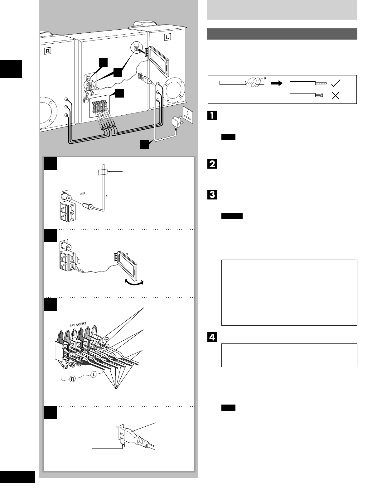
Connections
Basic connections (for supplied accessories)
•
Plug the AC mains lead into a household mains socket only after
all other connections have been made.
•
To prepare the AM loop antenna wires and speaker cords, twist
the vinyl cover tip and pull off.
Connect the FM indoor antenna.
Tape the antenna to a wall or column, in a position where radio
signals are received with the least amount of interference.
Note
For best reception sound quality:
An FM outdoor antenna is recommended. (See page 7.)
Connect the AM loop antenna.
After attaching the antenna, turn on the system and tune in a
broadcast station. Then, turn the antenna to the angle of best
reception and least interference.
Connect the speaker cables.
Connect each end of the speaker cables to the terminal lever of
the same colour.
Caution
•
Use only the supplied speakers.
The combination of the main unit and speakers provide the
best sound. Using other speakers can damage the unit and
sound quality will be negatively affected.
•
To prevent damage to circuitry, never short-circuit positive (+)
and negative (–) speaker wires.
Caution
• Use the speakers only with the recommended
system.
Failure to do so may lead to damage to the
amplifier and/or the speakers, and may result in
the risk of fire.
Consult a qualified service person if damage has
occurred or if you experience a sudden change
in performance.
• Do not attach these speakers to walls or ceilings.
Connect the AC mains lead.
(FOR UNITED KINGDOM ONLY)
BE SURE TO READ THE CAUTION FOR THE AC
MAINS LEAD ON PAGE 4 BEFORE CONNECTION.
Insertion of connector
Even when the connector is perfectly inserted, depending on
the type of inlet used, the front part of the connector may jut out
as shown in the drawing.
However there is no problem using the unit.
Note
The included AC mains lead is for use with this unit only. Do
not use it with other equipment.
Black (–)
To household
mains socket
7
Before using
RQT5321
A
B
C
R L
(L)(R)
D
OPTICAL
IN
OPTICAL OUT
OPTICAL OUT
OPTICAL OUT
LOOP
EXT
AM ANT
5 -12
m
FM ANT
( )
Rear panel of this unit
FM outdoor antenna
(not included)
AM loop antenna
(included)
75
Ω coaxial cable
(not included)
Analog player
(not included)
AM outdoor antenna (not included)
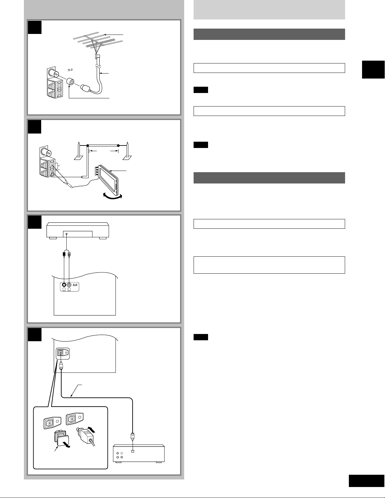
Connections
Optional antenna connections
You may need an outdoor antenna if you use this system in a
mountainous region or inside a reinforced-concrete building, etc.
FM outdoor antenna A
Disconnect the FM indoor antenna if an FM outdoor antenna is installed.
Note
An outdoor antenna should be installed by a qualified technician only.
AM outdoor antenna B
Connect the outdoor antenna without removing the AM loop antenna.
Run 5 to 12
m of vinyl-covered wire horizontally along a window or
other convenient location.
Note
When the unit is not in use, disconnect the outdoor antenna to prevent
possible damage that may be caused by lightning. Never use an
outdoor antenna during an electrical storm.
External unit connection
•
Make sure that the power supply for all components has been
turned off before making any connections.
•
For details, refer to the operating instructions of the unit which are
to be connected.
Connecting analog equipment C
An analog player with a built-in phono equalizer can be connected.
When units other than those described are to be connected, please
consult your audio dealer.
Connecting digital equipment to the optical
fibre out terminal D
Remove the dust-protection cap and connect this unit to other digital
equipment with an optical fibre terminal, such as a receiver or digital
surround processor.
•
Leave the cap attached when this terminal is not being used.
For your reference
If you have DTS format CDs, you can enjoy six channel playback by
connecting this unit to a receiver or digital surround processor that
has a DTS decoder.
Note
Use only the optical fibre terminal when playing back DTS format
discs. DTS signals can only be correctly output through the digital
terminal.
¡ DTS is a trademark of Digital Theater Systems, L.P.
Rear panel of this unit
Optical fibre cable
(not included)
Receiver
(not included)
Dust-protection cap
Antenna plug adaptor
(included)
8
Before using
RQT5321
A
B
13
10
9
3
1
2
5
4
6
7
8
14
15
11
12
REC
PLAY
CLOCK
TIMER
SOUND CONTROL JOG
TRI-AMP CONTROL
DECK 2
OPEN
OPEN
DECK 1
REV MODE
TAPE EDIT
a
REC/STOP
TUNE MODE
TUNE TIME ADJ
TUNE TIME ADJ
FM MODE BP
MEMORY
LOW
MID HIGH
TRI-AMP
3D AI EQ
16 17 18 19 20 21 22
23 27262524 28
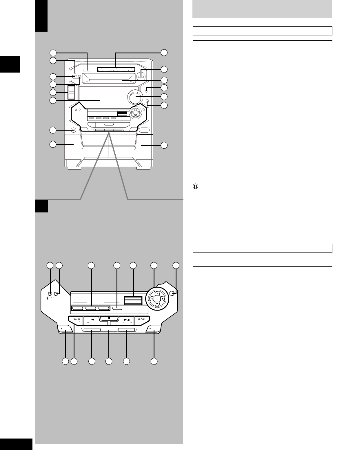
Front panel controls
Main unit A
No. Name Ref. page
1 CD manager button
(CD MANAGER) ...................................................17, 23
2 AC supply indicator (AC IN)
This indicator lights when the unit is connected to the AC mains
supply.
3 Standby/on switch (f/I) .............................................. 9
Press to switch the unit from on to standby mode or vice versa.
In standby mode, the unit is still consuming a small amount of
power.
4 Eco button (MODE)..................................................... 9
5 Input select buttons and indicators (CD, TUNER BAND,
TAPE DECK 1/2, AUX) .............................11, 17, 18, 29
6 Display
7 Headphone jack (PHONES) ...................................... 29
8 Deck 1 cassette holder..............................................18
9 Disc direct play, open/close buttons and indicators
(CD 1 ~ CD 5, c) ........................................................14
! Random play button (RANDOM).............................. 15
Disc tray
# Display select/demonstration button
(-DISPLAY/–DEMO) ............................................... 9, 29
$ Volume control (VOLUME) ........................................12
% Super woofer on/off button and indicator
(S.WOOFER)...............................................................24
& Deck 2 cassette holder..............................................18
Center console B
No. Name Ref. page
( Play timer/record timer button and indicator
(rPLAY/rREC) ..........................................................27
) Clock/timer button
(CLOCK/TIMER)..............................................10, 27, 28
~ TRI-AMP control buttons (LOW, MID, HIGH) .......... 26
+ TRI-AMP indicator (TRI-AMP)................................... 26
, Jog control (SOUND CONTROL JOG)............... 24, 26
- Joy stick .....................................................................25
. 3D AI EQ button (3D AI EQ) ..................................... 25
/ Deck 1 open button (c DECK 1 OPEN) .................. 18
: Basic operating buttons
Functions change according to the source.
; Tape edit button (TAPE EDIT).................................. 20
< Recording start/stop button (a REC/STOP)............ 21
= Reverse mode select button (REV MODE).............. 18
> Deck 2 open button (c DECK 2 OPEN) .................. 18
9
Before using
RQT5321
3
35
37
30
29
31
33
22
34
10
38
39
40
41
5
14
13
32
36
A
B
C
MODE
MODE
DISPLAY
DEMO
DISPLAY
DEMO
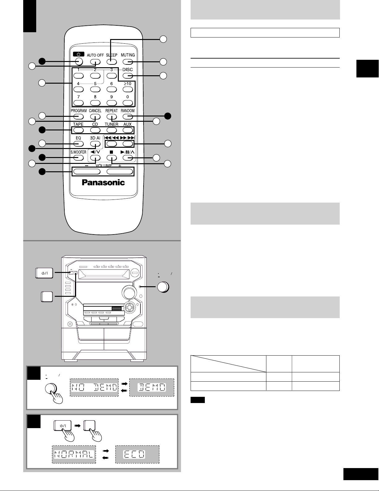
Remote control A
Buttons 3, 5, !, $, % and . have the same functions as the
corresponding buttons on the main unit.
No. Name Ref. page
? Auto off button (AUTO OFF) .................................... 10
@ Numeric buttons (≥10, 1
–
0)............................... 12, 15
[ Program button (PROGRAM) ................................... 16
\ Cancel button (CANCEL)...........................................16
] EQ select button (EQ) ................................................24
^ Reverse side playback/preset channel select
button (//3)........................................................12, 18
_ Sleep button (SLEEP) ................................................26
{ Muting button (MUTING) ...........................................29
| Disc button (DISC) .....................................................15
} Repeat button (REPEAT)...........................................15
V Skip/search buttons (
gg
gg
g/
((
((
(,
))
))
)/
ff
ff
f)........ 14, 19
0 Play/pause/preset channel select
button (-/J/4) ..............................................12, 14, 18
1 Stop button (L) ....................................................14, 18
Front panel controls
Turning the demo function off
B
If the clock has not been set, a demonstration of the display is shown
when the unit is switched to standby.
This function is set to on at the time of purchase.
Turn this function off to get the most from the eco mode (see below).
Press and hold [-DISPLAY/–DEMO] until “NO DEMO” is
displayed.
The display changes each time the button is held down.
NO DEMO (off) ↔DEMO (on)
ECO mode
C
When this mode is used, the display remains blank when the unit
is switched to standby mode and the power consumed is reduced
to 0.4
W from a maximum of 14
W.
The mode is set to on at the time of purchase.
Condition in standby
ECO mode
Display Power consumption
off clock 14
W
on blank 0.4
W
Note
To get the most from this mode, turn the demo function off or set the
clock.
Turning ECO on and off
Press [f/7] to turn the unit on.
Press [MODE].
The current ECO mode is displayed. Press again to change the mode.
The display changes each time the button is pressed.
NORMAL (off) ↔ ECO (on)
The eco mode can be turned on if the unit is in standby but it cannot
be turned off.

10
Before using
RQT5321
1
2
3
4
A
CLOCK
TIMER
CLOCK
TIMER
TUNE TIME ADJ
TUNE TIME ADJ
B
1
2
4
3
DISPLAY
DEMO
Setting the time
B
This is a 24-hour display clock.
This example in the figure shows how to set the time for 16:25
(4:25 p.m.).
Press [
ff
ff
f/
77
77
7] to switch on the system.
Press [CLOCK/TIMER] to select “CLOCK”.
Every time you press the button:
CLOCK RECPLAY
(within 7 seconds or so)
Press [TUNE/TIME ADJ (3) or (4)] to show the
present time.
Press [CLOCK/TIMER] to finish setting the time.
The display will return to whatever was displayed before you
set the time.
To display the time when system is ON
Press [CLOCK/TIMER] to select “CLOCK”.
At ECO mode on, to display the time when system is OFF
Press [-DISPLAY/–DEMO].
The time will be displayed for about 5 seconds and then the display
will return to whatever was previously displayed.
Previous display
Auto-off function
A
by remote control only
When CD or tape is selected as the source
To save power, the unit turns off if it is left unused for four minutes.
Note
This function does not work if the source is tuner or AUX.
Press [AUTO OFF].
“AUTO OFF” is shown on the display.
To cancel
Press [AUTO OFF] again to clear “AUTO OFF” from the display.
For your reference
The setting is maintained even if the unit is turned off. When the unit is
turned on again, “AUTO OFF” is displayed and the unit functions as
described above.
“AUTO OFF” disappears from the display if either tuner or AUX is
selected as the source but continues to function normally.
“AUTO OFF” remains displayed if CD or tape is selected as the source.
 Loading...