


Panasonic SC-AK200EB, SC-AK300EB, SC-AK300E, SC-AK200E, SC-AK200GN User Manual
...
CD Stereo System
Operating Instructions
Model No. SC-AK300
SC-AK200
The illustrations show SC-AK300.
E 
 EB
EB 
 EE
EE 
 GN
GN
Note:
“EB” on the packaging indicates the United
Kingdom.
Before connecting, operating or adjusting this product, please read these instructions completely. Please keep this manual for future reference.
RQT6131-1B
Dear customer
Thank you for purchasing this product.
For optimum performance and safety, please read these instructions carefully.
These operating instructions are applicable to the following system. These operating instructions, however, fundamentally explain the operation of system SC-AK300.
|
|
System |
SC-AK300 |
SC-AK200 |
usingBefore |
|
|
|
|
|
Main unit |
SA-AK300 |
SA-AK200 |
|
|
|
|||
|
|
|
|
|
|
|
Speakers |
SB-AK300 |
SB-AK200 |
|
|
|
|
|
|
|
|
|
|
|
|
|
|
|
LUOKAN 1 LASERLAITE
KLASS 1 LASER APPARAT
(Back of product)
|
|
DANGER |
INVISIBLE LASER RADIATION WHEN OPEN. |
|
|
||
|
|
AVOID DIRECT EXPOSURE TO BEAM. |
|
|
|
|
|
|
|
ADVARSEL |
USYNLIG LASERSTRÅLING VED ÅBNING, NÅR SIKKERHEDSAFBRYDERE |
|
|
ER UDE AF FUNKTION. UNDGÅ UDSÆTTELSE FOR STRÅLING. |
|
|
|
|
|
|
|
VARO! |
AVATTAESSA JA SUOJALUKITUS OHITETTAESSA OLET ALTTIINA |
|
|
NÄKYMÄTÖNTÄ LASERSÄTEILYLLE. ÄLÄ KATSO SÄTEESEEN. |
|
|
|
|
|
|
|
VARNING |
OSYNLIG LASERSTRÅLNING NÄR DENNA DEL ÄR ÖPPNAD OCH |
|
|
SPÄRREN ÄR URKOPPLAD. BETRAKTA EJ STRÅLEN. |
|
|
|
|
|
|
|
ADVARSEL |
USYNLIG LASERSTRÅLING NÅR DEKSEL ÅPNES OG SIKKERHEDSLÅS |
|
|
BRYTES. UNNGÅ EKSPONERING FOR STRÅLEN. |
|
|
|
|
|
|
|
VORSICHT |
UNSICHTBARE LASERSTRAHLUNG, WENN ABDECKUNG GEÖFFNET. |
|
|
|
NICHT DEM STRAHL AUSSETZEN. |
Inside of product
Tuotteen sisällä
Produktets innside
2
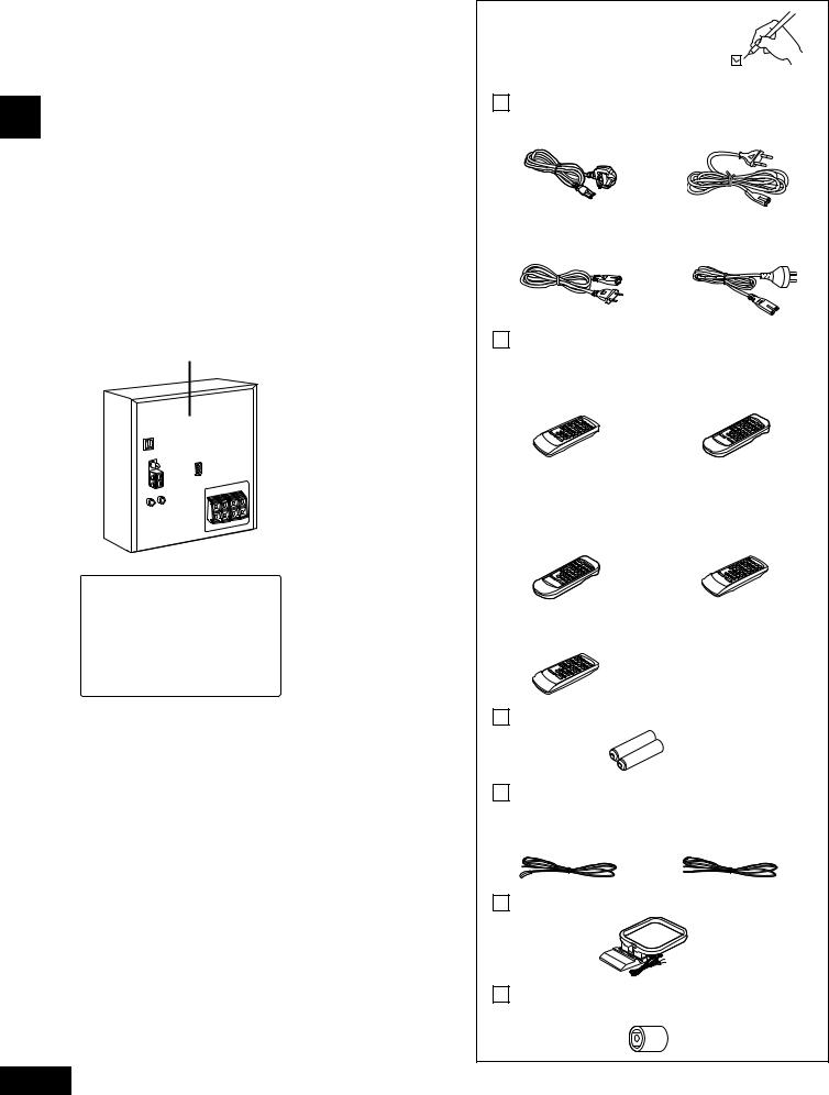
Supplied accessories
Please check and identify the supplied accessories.
AC mains lead .............................................. |
1 pc. |
For United Kingdom |
For Continental Europe |
(RJA0044-3C) |
(RJA0043-1C) |
For Russia and Ukraine |
For Australia and |
(RJA0019-2X) |
New Zealand |
|
(RJA0035-X) |
Remote control transmitter ......................... |
1 pc. |
||
SC-AK300 |
|
|
|
For Europe |
For Australia and |
|
|
(N2QAGB000015) |
New Zealand |
|
|
|
|
(N2QAGB000017) |
|
SC-AK200 |
|
|
For United Kingdom, |
For Continental |
|
Continental Europe, |
Europe, Russia |
|
Australia and New Zealand |
and Ukraine only |
|
Silver: (N2QAGB000013) |
Black: (N2QAGB000016) |
|
For Russia and Ukraine
Silver: (N2QAGB000015)
Batteries for remote control ...................... |
2 pcs. |
FM indoor antenna |
....................................... |
1 pc. |
For Europe |
For Australia and |
|
(RSA0007-J) |
New Zealand |
|
|
(RSA0006 - J) |
|
AM loop antenna (N1DADYY00002) ............ |
1 pc. |
|
Antenna plug adaptor (for United Kingdom only) (SJP9009) ...................................................... 1 pc.
Use numbers indicated in parentheses when asking for replacement parts.
RQT6131

Table of contents |
|
Before using |
|
Supplied accessories .............................................. |
2 |
Safety precautions ................................................... |
3 |
Caution for AC Mains Lead ..................................... |
4 |
Concerning the remote control .............................. |
5 |
Battery installation ........................................................... |
5 |
Correct method of use .................................................... |
5 |
Placement of speakers ............................................ |
5 |
Connections ............................................................. |
6 |
Basic connections (for supplied accessories) .................. |
6 |
Optional antenna connections ......................................... |
7 |
External unit connection .................................................. |
7 |
Front panel controls ................................................ |
8 |
Turning the demo function off .............................. |
10 |
Convenient functions ............................................ |
10 |
Auto-off function .................................................... |
11 |
Setting the time ...................................................... |
11 |
Radio operations |
|
Listening to radio broadcasts ............................... |
12 |
Presetting radio broadcasts ................................. |
13 |
Compact disc operations |
|
Concerning compact discs ................................... |
14 |
Listening to compact discs .................................. |
15 |
Program play ................................................................. |
16 |
To listen to specific CDs and tracks (CD Play Mode |
|
function) ........................................................................ |
17 |
Direct access play ......................................................... |
18 |
Repeat play ................................................................... |
18 |
CD display ..................................................................... |
18 |
Cassette deck operations |
|
Listening to tapes .................................................. |
19 |
Recording operations |
|
Before recording (Deck 2 only) ............................ |
20 |
Recording from compact discs ............................ |
21 |
Recording from radio broadcasts ........................ |
21 |
Tape-to-tape recording .......................................... |
22 |
Sound quality operations |
|
Using the built-in sound quality settings ............. |
22 |
Enhancing the sound quality ................................ |
22 |
Timer operations |
|
Using the timers .................................................... |
23 |
Using the play/record timer ........................................... |
23 |
Using the sleep timer .................................................... |
25 |
Reference |
|
Using an external unit ........................................... |
25 |
Troubleshooting guide .......................................... |
26 |
Maintenance ........................................................... |
26 |
Specifications ........................................................ |
27 |
Safety precautions
Placement
Set the unit up on an even surface away from direct sunlight, high |
|
|
temperatures, high humidity, and excessive vibration. These |
|
|
conditions can damage the cabinet and other components, thereby |
|
|
shortening the unit’s service life. |
|
|
Place it at least 15 cm away from wall surfaces to avoid distortion |
|
|
and unwanted acoustical effects. |
|
|
Do not place heavy items on the unit. |
using |
|
Voltage |
||
Before |
||
and cause a fire. |
Do not use high voltage power sources. This can overload the unit
Do not use a DC power source. Check the source carefully when setting the unit up on a ship or other place where DC is used.
AC mains lead protection
Ensure the AC mains lead is connected correctly and not damaged. Poor connection and lead damage can cause fire or electric shock. Do not pull, bend, or place heavy items on the lead.
Grasp the plug firmly when unplugging the lead. Pulling the AC mains lead can cause electric shock.
Do not handle the plug with wet hands. This can cause electric shock.
Foreign matter
Do not let metal objects fall inside the unit. This can cause electric shock or malfunction.
Do not let liquids get into the unit. This can cause electric shock or malfunction. If this occurs, immediately disconnect the unit from the power supply and contact your dealer.
Do not spray insecticides onto or into the unit. They contain flammable gases which can ignite if sprayed into the unit.
Service
Do not attempt to repair this unit by yourself. If sound is interrupted, indicators fail to light, smoke appears, or any other problem that is not covered in these instructions occurs, disconnect the AC mains lead and contact your dealer or an authorized service center. Electric shock or damage to the unit can occur if the unit is repaired, disassembled or reconstructed by unqualified persons.
Extend operating life by disconnecting the unit from the power source if it is not to be used for a long time.
3
RQT6131
Caution for AC Mains Lead
(For United Kingdom)
(“EB” area code model only)
For your safety, please read the following text carefully.
|
This appliance is supplied with a moulded three pin |
||
using |
mains plug for your safety and convenience. |
||
Should the fuse need to be replaced please ensure that |
|||
Before |
A 5-ampere fuse is fitted in this plug. |
||
the replacement fuse has a rating of 5-ampere and that |
|||
|
|||
|
it is approved by ASTA or BSI to BS1362. |
||
|
Check for the ASTA mark |
or the BSI mark on the |
|
|
|||
|
body of the fuse. |
|
|
If the plug contains a removable fuse cover you must ensure that it is refitted when the fuse is replaced.
If you lose the fuse cover the plug must not be used until a replacement cover is obtained.
A replacement fuse cover can be purchased from your local dealer.
CAUTION!
IF THE FITTED MOULDED PLUG IS UNSUITABLE FOR THE SOCKET OUTLET IN YOUR HOME THEN THE FUSE SHOULD BE REMOVED AND THE PLUG CUT OFF AND DISPOSED OF SAFELY.
THERE IS A DANGER OF SEVERE ELECTRICAL SHOCK IF THE CUT OFF PLUG IS INSERTED INTO ANY 13-AMPERE SOCKET.
If a new plug is to be fitted please observe the wiring code as stated below.
If in any doubt please consult a qualified electrician.
IMPORTANT
The wires in this mains lead are coloured in accordance with the following code:
Blue: Neutral, Brown: Live.
As these colours may not correspond with the coloured markings identifying the terminals in your plug, proceed as follows:
The wire which is coloured Blue must be connected to the terminal which is marked with the letter N or coloured Black or Blue.
The wire which is coloured Brown must be connected to the terminal which is marked with the letter L or coloured Brown or Red.
4
WARNING: DO NOT CONNECT EITHER WIRE TO THE EARTH TERMINAL WHICH IS MARKED WITH THE LETTER E, BY THE EARTH SYMBOL i OR
COLOURED GREEN OR GREEN/YELLOW.
THIS PLUG IS NOT WATERPROOF—KEEP DRY.
Before use
Remove the connector cover.
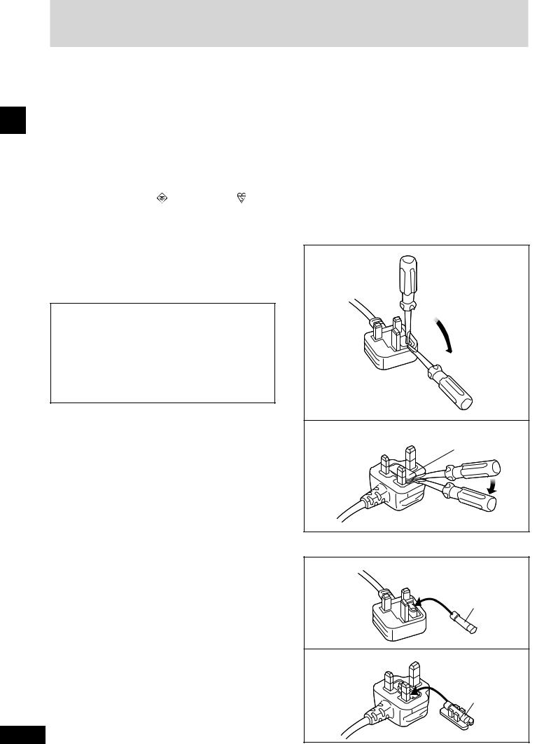
How to replace the fuse
The location of the fuse differ according to the type of AC mains plug (figures A and B). Confirm the AC mains plug fitted and follow the instructions below.
Illustrations may differ from actual AC mains plug.
1.Open the fuse cover with a screwdriver.
Figure A
Figure B
Fuse cover
2.Replace the fuse and close or attach the fuse cover.
Figure A
Fuse
(5 ampere)
Figure B
Fuse
(5 ampere)
RQT6131

A For SC-AK300: Australia and New Zealand
For SC-AK200: United Kingdom, Continental Europe, Australia and New Zealand
R6, AA, UM-3
For SC-AK300: Europe
For SC-AK200: Continental Europe, Russia and Ukraine only
R6/LR6, AA, UM-3
B
Remote control signal sensor
30˚ |
30˚ |
Transmission |
|
window |
About 7 meters in front of |
|
|
|
the signal sensor |
C
SC-AK300
Super tweeter
SC-AK200
Concerning the remote control
 A Battery installation
Use of batteries
• Align the poles (+ and –) properly when inserting the batteries. |
|
||
|
|||
• Do not mix old and new batteries or different types of batteries. |
|
||
• Do not recharge ordinary dry cell batteries. |
|
||
• Do not heat or disassemble the batteries. Do not allow them to |
using |
||
|
contact flame or water. |
||
• Remove the batteries if the unit is not to be used for a long time. |
|
||
• Do not keep together with metallic objects such as necklaces. |
Before |
||
• |
Do not use rechargeable type batteries. |
||
|
|||
• Do not use batteries if the covering has been peeled off.
Mishandling of batteries can cause electrolyte leakage which can damage items the fluid contacts and may cause a fire.
If electrolyte leaks from the batteries, consult your dealer.
Wash thoroughly with water if electrolyte comes in contact with any part of your body.
 B Correct method of use
Operation notes
•Do not place obstacles between the remote control signal sensor and remote control unit.
•Do not expose the remote control signal sensor to direct sunlight or to the bright light of a fluorescent light.
•Take care to keep the remote control signal sensor and end of the remote control unit free from dust.
•If this system is installed in a rack with glass doors, the glass doors’ thickness or colour might make it necessary to use the remote control a shorter distance from the system.
To prevent damage
•Never place heavy items on top of the unit.
•Do not disassemble or reconstruct the unit.
•Do not spill water or other liquids into the unit.
C Placement of speakers
SC-AK300
Place the speakers so that the super tweeter is on the outside.
SC-AK200
Speakers are designed identically so that no left or right channel orientation is necessary.
Notes
•Keep your speakers at least 10 mm away from the system for proper ventilation.
•These speakers do not have magnetic shielding. Do not place them near televisions, personal computers or other devices easily influenced by magnetism.
•To avoid damage to the speakers, do not touch the speaker cones if you have taken the nets off.
5
RQT6131

1
|
3 |
|
2 |
using |
|
Before |
To household |
|
4 mains socket
1 |
For Australia and |
|
For Europe |
||||||
New Zealand |
|
|
|
|
|
||||
|
|
|
|
|
Adhesive tape |
|
|
|
|
|
FM |
ANT |
|
|
FM indoor antenna |
||||
|
) |
|
|
|
|
|
|
|
|
|
( |
|
|
|
|
|
|
|
|
|
|
|
|
|
|
|
|
T |
|
1 |
|
|
|
|
|
FM |
AN |
||
|
GND |
|
|
|
|
) |
|||
|
|
|
|
( |
|
||||
|
|
|
|
|
|
|
|
|
|
|
|
2 |
|
|
|
|
|
|
|
2 |
For Australia and |
For Europe |
|
|
|
||||
New Zealand |
|
|
|
|
|
||||
|
|
|
ANT |
AM |
ANT |
|
|
|
|
|
|
AM |
|
|
|
|
|||
|
|
|
LOOP |
|
|
|
|||
|
|
|
|
|
|
|
|
||
|
|
|
LOOP |
|
|
|
|
||
|
|
|
|
EXT |
|
|
|
||
|
|
|
EX |
T |
|
|
|
|
|
|
|
|
|
|
|
|
|
||
|
|
|
|
|
|
|
|
|
|
AM loop antenna |
|
|
|
|
|
||||
3 |
|
|
|
|
|
|
|
|
|
|
|
|
|
|
|
Red (+) |
|||
|
|
|
|
|
|
Black (–) |
|||
|
|
|
1 |
|
|
|
|
|
|
|
|
|
|
2 |
|
|
|
|
|
|
|
|
|
|
|
Blue (–) |
|||
|
|
|
|
|
|
Gray (+) |
|
|
|
|
|
|
|
Blue |
|
|
|
|
|
|
|
Gray |
Black |
|
|
|
|
||
|
|
Red |
|
|
|
|
|||
4 |
Appliance inlet |
|
Connector |
||||||
|
|
|
|
|
|||||
6 |
|
Approx. 6 mm |
|
|
|
|
|
||
RQT6131 |
|
|
|
|
|
|
|
|
|
Connections
Basic connections (for supplied accessories)
•Plug the AC mains lead into a household mains socket only after all other connections have been made.
•To prepare the antenna wires and speaker cords, twist the vinyl cover tip and pull off.
1 Connect the FM indoor antenna.
Tape the antenna to a wall or column, in a position where radio signals are received with the least amount of interference.
Note
For best reception sound quality:
An FM outdoor antenna is recommended. (See page 7.)
2 Connect the AM loop antenna.
After attaching the antenna, turn on the system and tune in a broadcast station. Put the antenna where the reception is best and interference is minimal.
3 Connect the speaker cables.
Connect each end of the speaker cables to the terminal lever of the same colour so (+) and (–) are correct. Never allow the exposed wires to contact each other when connected.
Incorrect connection can damage the unit.
Caution
•Use only the supplied speakers.
The combination of the main unit and speakers provide the best sound. Using other speakers can damage the unit and sound quality will be negatively affected.
Caution
•Use the speakers only with the recommended system.
Failure to do so may lead to damage to the amplifier and/or the speakers, and may result in the risk of fire.
Consult a qualified service person if damage has occurred or if you experience a sudden change in performance.
•Do not attach these speakers to walls or ceilings.
4 Connect the AC mains lead.
FOR UNITED KINGDOM ONLY
READ THE CAUTION FOR THE AC MAINS LEAD ON PAGE 4 BEFORE CONNECTION.
Insertion of connector
Even when the connector is perfectly inserted, depending on the type of inlet used, the front part of the connector may jut out as shown in the drawing.
However there is no problem using the unit.
Note
The included AC mains lead is for use with this unit only. Do not use it with other equipment.
A |
|
For Australia and New Zealand |
|
||||||
|
|
|
|
|
|
|
FM outdoor antenna |
||
|
|
|
|
|
|
|
|
(not included) |
|
|
|
|
|
|
|
|
75 Ω coaxial cable (not included) |
||
|
|
|
|
|
|
|
1 |
|
|
|
|
|
|
ANT |
|
|
|
|
30 mm |
|
|
FM |
|
|
2 |
|
|
||
|
|
( |
|
) |
|
|
|
|
|
|
|
|
|
|
|
|
|
||
|
|
|
|
|
|
|
|
|
|
|
1 |
|
GND |
|
|
|
Shield braid |
||
|
|
|
|
|
|
|
|||
|
|
|
|
2 |
|
|
3 |
15 mm |
Core wire |
|
|
|
|
|
|
|
|
|
|
|
|
For Europe |
|
|
|
FM outdoor antenna |
|||
|
|
|
|
|
|
|
|
|
|
|
|
|
|
|
|
|
|
|
(not included) |
|
|
|
|
|
|
|
|
75 Ω |
coaxial cable |
|
|
|
|
|
|
FM ANT |
(not included) |
||
|
|
|
|
|
|
( |
) |
|
|
|
|
|
|
|
|
|
|
(For United Kingdom only) |
|
|
|
|
|
|
|
|
|
Antenna plug |
|
|
|
|
|
|
|
|
|
adaptor (included) |
|
B |
|
For Australia and New Zealand |
|
||||||
|
|
|
|||||||
|
|
|
|
|
|
|
|
|
AM outdoor antenna |
|
|
|
|
|
|
|
5 -12 m |
|
(not included) |
|
|
|
|
AM |
ANT |
|
|
|
|
|
|
|
|
|
|
|
|
|
|
|
|
|
|
|
LOO |
P |
|
|
|
|
|
|
|
|
|
|
|
|
|
|
|
|
|
|
EXT |
|
|
|
AM loop antenna |
|
|
|
|
|
|
|
|
|
|
|
|
|
|
|
|
|
|
|
(included) |
|
|
For Europe |
|
|
|
AM outdoor antenna |
|||
|
|
|
|
|
|
|
|
|
|
|
|
|
|
|
|
|
5 -12 m |
|
(not included) |
|
|
AM |
ANT |
|
|
|
|
|
|
|
|
|
|
|
|
|
|
|
|
|
|
|
LOOP |
|
|
|
|
|
|
|
|
|
EXT |
|
|
|
|
AM loop antenna |
|
|
|
|
|
|
|
|
|
|
|
|
|
|
|
|
|
|
|
|
(included) |
C |
|
|
|
|
|
|
|
|
|
|
|
|
R |
|
L |
|
Rear panel of this unit |
||
|
|
(R) |
|
|
|
(L) |
|
|
|
|
|
|
|
|
|
|
|
Analogue player |
|
|
|
|
|
|
|
|
|
(not included) |
|
D |
|
|
|
|
|
|
|
|
|
|
|
OPTICAL |
|
|
|
|
|
Rear panel of this unit |
|
|
|
OUT |
|
|
|
|
|
||
|
|
|
|
|
|
|
|
|
|
|
|
|
|
|
|
|
|
|
Optical fiber |
|
|
|
|
|
|
|
|
|
cable |
|
|
|
|
|
|
|
|
|
(not included) |
|
|
|
|
|
|
|
|
|
Receiver |
|
|
|
|
|
|
|
|
|
(not included) |
|
|
|
|
|
|
|
|
|
OPTICAL |
|
|
|
|
|
|
|
|
|
IN |
Connections
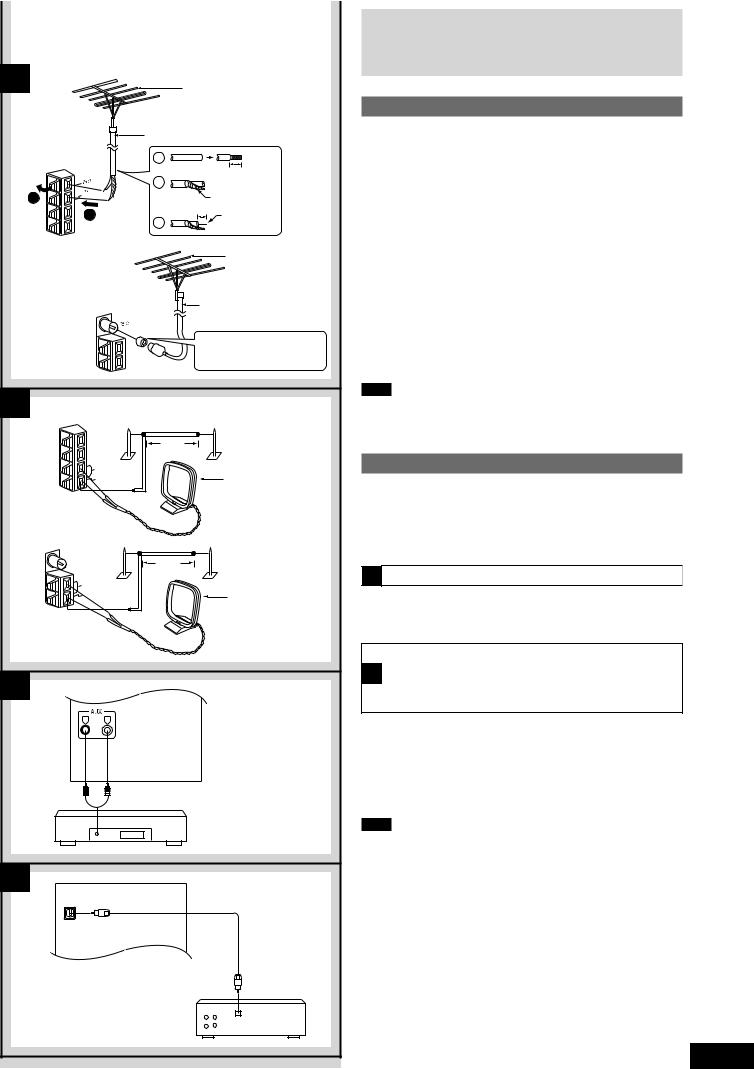
Optional antenna connections
You may need an outdoor antenna if you use this system in a mountainous region or inside a reinforced concrete building, etc.
|
|
|
|
A |
FM outdoor antenna |
|
|
Disconnect the FM indoor antenna if an FM outdoor antenna is in- |
|
||
|
|||
stalled. |
using |
||
1 Remove a piece of the outer vinyl insulator. |
|||
2 Twist the shield braid. |
|||
3 Expose the core wire. |
|
||
|
|
|
Before |
Note |
|
|
|
|
|
|
|
An outdoor antenna should be installed by a qualified technician only. |
|
||
|
|
|
|
B |
AM outdoor antenna |
|
|
|
|
|
|
Connect the outdoor antenna without removing the AM loop antenna.
Run 5 to 12 m of vinyl-covered wire horizontally along a window or other convenient location.
Note
When the unit is not in use, disconnect the outdoor antenna to prevent possible damage that may be caused by lightning. Never use an outdoor antenna during an electrical storm.
External unit connection
•Make sure that the power supply for all components has been turned off before making any connections.
•For details, refer to the operating instructions of the unit which are to be connected.
•All peripheral components and cables sold separately.
 C Connecting analogue equipment
An analogue player with a built-in phono equalizer can be connected. When units other than those described are to be connected, please consult your audio dealer.
Connecting digital equipment to the optical
Dfiber out terminal
(For SC-AK300 except Russia, Ukraine, Australia and New Zealand)
Connect this unit to other digital equipment with an optical fibre terminal, such as a receiver or digital surround processor.
For your reference
If you have DTS format CDs, you can enjoy six channel playback by connecting this unit to a receiver or digital surround processor that has a DTS decoder.
Note
Use only the optical fibre terminal when playing back DTS format discs. DTS signals can only be correctly output through the digital terminal.
¡ DTS is a trademark of Digital Theater Systems, L.P.
7
RQT6131

A
Before using
B
18 |
|
SUPER SOUND EQ |
|
|
|
|
|
|
|
|
|
19 |
AUX |
TUNER/BAND |
TAPE |
CD |
21 |
|
|||||
20 |
|
|
|
|
22 |
|
REW |
DEMO |
FF |
|
|
|
|
24 |
|
|
|
|
|
23 |
|
|
|
8
Front panel controls
A |
Main unit |
|
|
|
|
No. |
Name |
Ref. page |
|
|
|
1AC supply indicator (AC IN)
This indicator lights when the unit is connected to the AC mains supply.
2Standby/on switch (f/I)
Press to switch the unit from on to standby mode or vice versa. In standby mode, the unit is still consuming a small amount of power.
3 |
Display button (DISPLAY) .................................. |
12, 18 |
4 |
Display |
|
5 |
Preset EQ select button (PRESET EQ) ................... |
22 |
6 |
Record button (a REC) .............................................. |
21 |
7 |
Deck select button (DECK 1/2) ................................ |
19 |
8 |
Deck 1 open button (c DECK 1 OPEN) .................. |
19 |
9 |
Deck 1 cassette holder .............................................. |
19 |
! Disc tray |
|
|
|
Remote control signal sensor (SENSOR) ................. |
5 |
# Disc direct play buttons (1 ~ 5) ............................... |
15 |
|
$ CD tray open/close button (c) ................................ |
15 |
|
% Volume control (VOL DOWN, UP) ............................ |
12 |
|
& Headphone jack (PHONES) ...................................... |
25 |
|
( Deck 2 open button (c DECK 2 OPEN) .................. |
19 |
|
) Deck 2 cassette holder .............................................. |
19 |
|
B |
Center console |
|
~ Super sound EQ button (SUPER SOUND EQ) ........ |
22 |
|
+ AUX button (AUX) ...................................................... |
25 |
|
, Tuner/band select button (TUNER/BAND) .............. |
12 |
|
- CD play/pause button (CD :/ J) .............................. |
15 |
|
. Tape play button (TAPE :) ...................................... |
19 |
|
/CD skip/search, tape fast-forward/rewind, tune/preset channel select, time adjust buttons
(g/REW/3, 4/FF/f) ................. |
11, 12, 13, 15, 19 |
: Stop/program clear and demonstration button |
|
(L/–DEMO) ................................................ |
10, 15, 16, 19 |
RQT6131
|
|
SLEEP |
CLOCK |
PLAY |
|
2 |
|
AUTO OFF TIMER |
REC |
28 |
|
|
|
|
|
||
25 |
1 |
2 |
3 |
DISC |
29 |
|
|
||||
|
|
|
|
|
30 |
26 |
4 |
5 |
6 |
10 |
|
|
7 |
8 |
9 |
0 |
|
|
DISPLAY |
DIMMER |
PLAY MODE PROGRAM |
|
|
3 |
|
|
|
|
31 |
27 |
AUX |
TUNER |
TAPE |
CD |
32 |
|
21 |
||||
19 |
|
|
|
|
|
20 |
|
REW |
FF |
|
22 |
|
|
|
|
||
23 |
|
|
|
|
33 |
|
|
S.SOUND EQ |
PRESET EQ |
MUTING |
|
18 |
|
|
|
|
34 |
|
|
VOLUME |
|
5 |
|
|
|
|
|
||
14
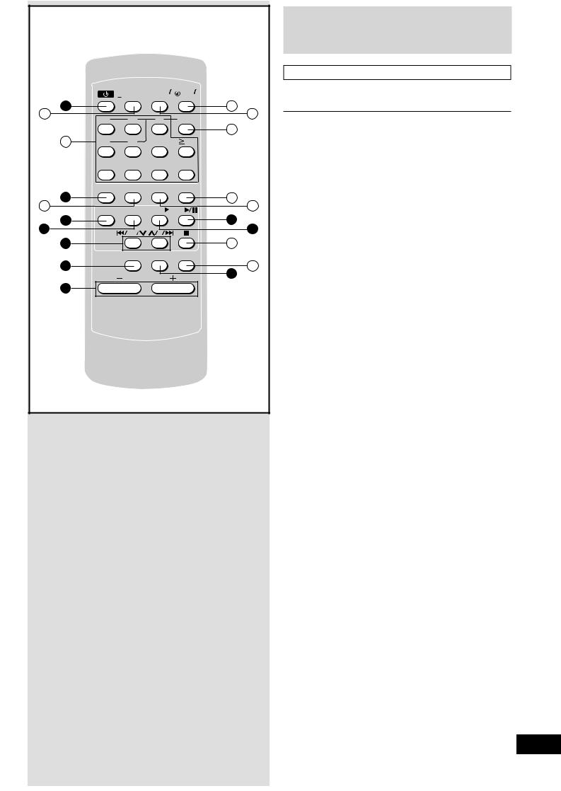
Front panel controls
Remote control
Buttons such as 2 function in exactly the same way as the buttons on the main unit.
No. |
Name |
|
Ref. page |
|
||
; Sleep timer/auto off button |
|
|
|
|
|
|
|
|
|
|
|
||
|
(SLEEP, –AUTO OFF) |
|
11, 25 |
|
|
|
|
|
|
using |
|||
< Numeric buttons (≥ 10, 1–9, 0) |
|
13, 16 |
|
|||
|
|
|
||||
= Dimmer button (DIMMER) ......................................... |
|
10 |
|
Before |
||
> Play timer/record timer button (rPLAY/REC) |
......... 23 |
|
||||
? Clock/timer button (CLOCK/TIMER) ............ |
11, 23, 24 |
|
||||
.....................................................@ Disc button (DISC) |
|
16 |
|
|
||
[ Program button (PROGRAM) ............................. |
|
13, 16 |
|
|
||
\ Play mode select button |
|
|
|
|
|
|
|
.....................................(PLAY MODE) |
12, 17, 18, 19, 21 |
|
|
||
] Stop/program clear button (L) ..................... |
15, 16, 19 |
|
|
|||
...........................................^ Muting button (MUTING) |
|
10 |
|
|
||
|
|
|
|
|
|
|
9
RQT6131
 Loading...