


FP-X
Table of contents
 Loading...
ARCT1F409E-3
'07・04
CTi Automation - Phone: 800.894.0412 - Fax: 208.368.0415 - Web: www.ctiautomation.net - Email: info@ctiautomation.net

Safety Precautions
Observe the following notices to ensure personal safety or to prevent accidents.
To ensure that you use this product correctly, read this User
’s Manual thoroughly before use.
Make sure that you fully understand the product and information on safe.
This manual uses two safety flags to indicate different levels of danger.
WARNING
If critical situations that could lead to user’s death or serious injury is assumed by
mishandling of the product.
-Always take precautions to ensure the overall safety of your system, so that the whole
system remains safe in the event of failure of this product or other external factor.
-Do not use this product in areas with inflammable gas. It could lead to an explosion.
-Exposing this product to excessive heat or open flames could cau
se damage to the lithium
battery or other electronic parts.
CAUTION
If critical situations that could lead to user’s injury or only property damage is assumed
by mishandling of the product.
-To prevent abnormal exothermic heat or smoke generation, use thi
s product at the values less
than the maximum of the characteristics and performance that are assure in these specifications.
-Do not dismantle or remodel the product. It could lead to abnormal exothermi
c heat or
smoke generation.
-Do not touch the terminal while turning on electricity. It could lead to an electric shock..
-Use the external devices to function the
emerge
ncy stop and interlock circuit.
-Connect the wires or connectors securely.
The loose connection might cause abnormal exothermic heat or smoke generation
-Ground the protective earth (PE) terminal (Class
D groundi
ng). Failure to do so could lead to
an electric shock.
-Do not allow foreign matters such as liquid, flammable materials, metals to go into the
inside of the prod
uct. It might cause exothermic heat or smoke generation.
-Do not undertake construction (such as connection and disconnection) while the power
supply is on.
Copyright / Trademarks
-This manual and its contents are copylighted.
-You may not copy this manual,in whole or part,without written consent of Matsushita Electric
Works,Lt
d.
-Windows and Windows NT are registered trademarks of Microsof
t Corporation in the
United States and/o r othe r countries.
-All other company names and product name
s are tradem
arks or registered
trademarks of their respective owners.
-Matsushita Electric Works,Ltd. pursues a policy of co
ntinuous imp
rovement of the
Design and performan e of its products, therefore,we re
serve the right to change the manual/ c
product without notice.
CTi Automation - Phone: 800.894.0412 - Fax: 208.368.0415 - Web: www.ctiautomation.net - Email: info@ctiautomation.net

Table of Contents
Before You Start
Differences in Functions Between Versions of Controller
Programming Tool Restrictions
1. Features, Functions and Restrictions................................................. 1-1
1.1 Features and Functions of the Unit...............................................................................1-2
1.2 Unit Types ........................................................................................................................1-6
1.2.1 FP-X Control Units......................................................................................................1-6
1.2.2 FP-X Expansion Unit...................................................................................................1-7
1.2.3 FP-X Expansion FP0 Adapter.....................................................................................1-7
1.2.4 Add-on Cassettes
(Communication cassettes/Application cassettes)........................1-8
1.2.5 Related Parts ..............................................................................................................1-9
1.3 Restrictions on Unit Combinations .............................................................................1-10
1.3.1 Restrictions on FP-X Expansion Unit
........................................................................1-10
1.4 Programming Tools.......................................................................................................1-14
1.4.1 Tools Needed for Programm
ing................................................................................1-14
1.4.2 Software Environment and Suitable Cable...............................................................1-1
4
2. Specifications and Functions of Control Unit....................................2-1
2.1 Parts and Functions........................................................................................................2-2
2.1.1 Parts and Functions....................................................................................................2-2
2.2 Powe
r Supply Specifications .........................................................................................2-5
2.2.1 AC Power Supply........................................................................................................2-5
2.2.2 Service Power Supply for Input (Output) (A
C Power Supply Type Only)...................2-5
2.2.3 DC Power Supply........................................................................................................2-5
2.3 Input Specifications ........................................................................................................2-6
2.3.1 Relay (Ry) Type..........................................................................................................2-6
2.3.2 Transi
s
tor (Tr) Type (Common to NPN and PNP)......................................................2-7
2.4 Output Specifications .....................................................................................................2-8
2.4.1 Relay (Ry) Type..........................................................................................................2-8
2.4.2 Transis
tor (Tr) Type (NPN).........................................................................................2-9
2.4.3 Transis
tor (Tr) Type (PNP) .......................................................................................2-10
2.5 Terminal Layout
.............................................................................................................2-14
2.5.1 Relay Type................................................................................................................2-14
2.5.2 Transistor type
..........................................................................................................2-16
CTi Automation - Phone: 800.894.0412 - Fax: 208.368.0415 - Web: www.ctiautomation.net - Email: info@ctiautomation.net

ii
3. Expansion Cassette and Expansion FP0 Adapter Specifications ....3-1
3.1 Expansion Method...........................................................................................................3-2
3.1.1 Expansion Using the Expansion Cable.......................................................................3-2
3.2 FP-X Expansion Unit .......................................................................................................3-4
3.2.1 Parts and Functions
....................................................................................................3-4
3.2.2 Power Supply Specifications.......................................................................................3-5
3.2.3 Input and output specifications ...................................................................................3-6
3.2.4 Terminal layout............................................................................................................3-9
3.3 FP-X Expansion FP0 Adapter
.......................................................................................3-1
2
3.3.1 Overview ...................................................................................................................3-12
3.3.2 Parts and Functions
..................................................................................................3-13
4. I/O Allocation.........................................................................................4-1
4.1 I/O Allocation....................................................................................................................4-2
4.2 Allocation of FP-X Control Unit......................................................................................4-3
4.3 FP0 Expansion Unit Allocation
......................................................................................4-3
4.4 Allocation of FP0 Expansion Unit..................................................................................4-4
4.4.1 I/O A
llocation
...............................................................................................................4-4
4.4.2 Number of Expansion Units and I/O Allocation...........................................................4-4
4.4.3 I/O Allocation of FP0 Expansion Unit..........................................................................4-5
4.5 I/O Allocation of FP-X Add-on Cassette........................................................................4-6
5. Installation and Wiring..........................................................................5-1
5.1 Installation........................................................................................................................5-2
5.1.1 Installation Environment and Space ...........................................................................5-2
5.2 Installation Using Expansion Cable...............................................................................5-5
5.3 Expansion Method of FP0 Expansion Unit ...................................................................5-8
5.4 How
to Install Add-on Cassette......................................................................................5-9
5.5 Powe
r Supply.................................................................................................................5-11
CTi Automation - Phone: 800.894.0412 - Fax: 208.368.0415 - Web: www.ctiautomation.net - Email: info@ctiautomation.net

iii
5.6 Wiring of Input and Output...........................................................................................5-15
5.7 Wiring of Terminal Block ..............................................................................................5-18
5.8 Wiring of Add-on Cassette Terminal Block ................................................................5-20
5.9 Installation and Setting of Backup Battery
.................................................................5-23
5.9.1 Installat
ion of Backup Battery ...................................................................................5-24
5.9.2 System R
egister Setting ...........................................................................................5-25
5.9.3 Time for Replacement of Back
up Battery.................................................................5-25
5.9.4 Lifetime of Backu
p Battery........................................................................................5-26
5.10 Safety Measu
res ..........................................................................................................5-27
5.10.1 Safety Measures.....................................................................................................5-27
5.10.2 Momentary Power Failures.....................................................................................5-27
5.10.3 Protection of Output Sections.................................................................................5-2
7
6. Tool Port and USB Port........................................................................ 6-1
6.1 Tool Port and USB Port...................................................................................................6-2
6.2 Functions of Tool Port ....................................................................................................6-3
6.2.1 Tool Port......................................................................................................................6-3
6.2.2 Tool Port Setting .........................................................................................................6-4
6.3 USB Port...........................................................................................................................6-6
6.3.1 Functions of USB Port
................................................................................................6-6
6.3.2 USB Port Setting.........................................................................................................6-7
6.3.3 USB Connection
.........................................................................................................6-8
6.3.4 USB Connection Procedure........................................................................................6-9
6.3.5 Installat
ion of FPWIN GR............................................................................................6-9
6.3.6 Installat
ion of USB Driver..........................................................................................6-10
6.3.7 Confirming COM Ports..............................................................................................6-1
8
6.3.8 Communication with FPWIN GR
...............................................................................6-20
6.3.9 Reinstallation of USB Driver
.....................................................................................6-21
6.3.10 Restric
tions on USB Communication......................................................................6-22
7. Communication Cassette..................................................................... 7-1
7.1 Functions and Types.......................................................................................................7-2
7.1.1 Overview of Communication Cassette........................................................................7-2
7.1.2 Functions of Communic
ation Cassette.......................................................................7-3
7.1.3 Communication Cassettes..........................................................................................7-7
7.1.4 Examples of Connection
...........................................................................................7-12
7.1.5 Names and Principl
e Applications of the Ports.........................................................7-13
7.1.6 About USB Port (For C30/C60 Only
)........................................................................7-14
7.2 Communication Specifications....................................................................................7-15
CTi Automation - Phone: 800.894.0412 - Fax: 208.368.0415 - Web: www.ctiautomation.net - Email: info@ctiautomation.net

iv
7.2.1 Precaution When Using RS485 Port.........................................................................7-18
7.3 Communication Function 1: Computer Link...............................................................7-19
7.3.1 Computer Link...........................................................................................................7-19
7.3.2 1:1 Communicati
on (Computer link) .........................................................................7-27
7.3.3 1:N Communication (Computer Link)
........................................................................7-30
7.3.4 MEWTOCOL Master (Sample Program)
..................................................................7-33
7.4 Communication Function 2: General-purpose Serial Communication....................7-3
5
7.4.1 General-purpose Serial Communication...................................................................7-3
5
7.4.2 Communication with External Devic
es......................................................................7-37
7.4.3 Connection with 1:1 Communication (General-purpos
e serial communication).......7-47
7.4.4 1:N Communication
(General-purpose Serial Communication)................................7-58
7.5 Communication Function 3: PC(PLC) Link.................................................................7-59
7.5.1 PC(PLC) Link............................................................................................................7-59
7.5.2 Setting Communication Parameters
.........................................................................7-61
7.5.3 Monitoring .................................................................................................................7-70
7.5.4 Connection Example of PC(PLC) Link......................................................................7-71
7.5.5 PC(PLC) Link Response
Time..................................................................................7-74
7.6 Communication Function 4: MODBUS RTU Communication...................................7-78
7.6.1 MODBUS RTU Communica
tion................................................................................7-78
7.6.2 MEWTOCOL Master (Sample Program)
..................................................................7-82
8. Application Cassette.............................................................................8-1
8.1 Expansion of Application Cassette ...............................................................................8-2
8.2 Application Cassettes.....................................................................................................8-3
8.3 Specifications ..................................................................................................................8-5
8.3.1 FP-X Analog Input Cassette........................................................................................8-5
8.3.2 FP-X Input Cassette....................................................................................................8-8
8.3.3 FP-X Output Cass
ette
...............................................................................................8-21
8.3.4 FP-X Pulse I/O Cassette...........................................................................................8-23
8.3.5 FP-X Master Memory Cass
ette.................................................................................8-26
9. High-speed Counter, Pulse Output and PWM Output Functions (For
Tr Type) .................................................................................................9-1
9.1 Overview of Each Functions...........................................................................................9-2
9.1.1 Usable Units and Cassettes........................................................................................9-2
9.1.2 Three Pulse I/O Functions ..........................................................................................9-2
9.1.3 Performance of Pulse I/O Func
tion
.............................................................................9-3
9.2.1 Specifications..............................................................................................................9-4
9.2.2 Functions Used and Restrictions................................................................................9-6
9.2.3 Booting Time.............................................................................................................9-10
CTi Automation - Phone: 800.894.0412 - Fax: 208.368.0415 - Web: www.ctiautomation.net - Email: info@ctiautomation.net

v
9.3 High-speed Counter Function......................................................................................9-11
9.3.1 Overview of High-speed Counter Function
...............................................................9-11
9.3.2 Input Modes and Count.............................................................................................9-11
9.3.3 Minimum Input Pulse Width......................................................................................9-12
9.3.4 I/O Allocation
.............................................................................................................9-13
9.3.5 Instruc
tions used with High-speed Counter Function...............................................9-13
9.3.6 Sample program (Control Unit and Main Unit I/O)....................................................9-16
9.4 Pulse Output Function..................................................................................................9-19
9.4.1 Overview of Pulse Output Function
..........................................................................9-19
9.4.2 Types of Pulse Output Method and Operation Modes .............................................9-2
0
9.4.3 I/O Allocation
.............................................................................................................9-23
9.4.4 Pulse output cont
rol instructions (F0) (F1)................................................................9-25
9.4.5 Wiring for Pulse Output Sample Program (F171 to F174)
........................................9-27
9.4.6 Positioning Control Instruc
tion F171 - Trapezoidal...................................................9-28
9.4.7 Positioning Control In
struction F171 – Home Return (Common to Transistor type) 9-33
9.4.8 Pulse Output Inst
ruction F172 – JOG operation.......................................................9-38
9.4.9 Positioning Control Inst
ruction F174 – Data Table Control ......................................9-42
9.4.10 Pulse Output Instruc
tion F175 – Linear Interpolation.............................................9-44
9.5 PWM Output Function (Pulse I/O Cassette)................................................................9-51
9.5.1 Overview of PWM Output Function...........................................................................9-51
9.5.2 Instruc
tion to be Used for PWM Output Function.....................................................9-51
10. High-speed counter, Pulse Output and PWM Output functions (For Ry
Type)....................................................................................................10-1
10.1 Overview of Each Functions ......................................................................................10-2
10.1.1 Usable Units and Cassettes....................................................................................10-2
10.1.2 Three Pulse I/O Func
tions......................................................................................10-2
10.1.3 Performance of Pulse I/O Func
tion.........................................................................10-3
10.2.1 Specifications
..........................................................................................................10-4
10.2.2 Functions
Used and Restrictions............................................................................10-7
10.2.3 Booting Time...........................................................................................................10-8
10.3 High-speed Counter Function....................................................................................10-9
10.3.1 Overview of High-speed Counter Function.............................................................10-9
10.3.2 Input Modes and Count...........................................................................................10-9
10.3.3 Minimu
m Input Pulse Width
..................................................................................10-10
10.3.4 I/O Allocation
.........................................................................................................10-11
10.3.5 Instructions used with High-speed Counter Function
...........................................10-11
10.3.6 Sample program (Control Unit and Main Unit I/O)................................................10-14
10.3.7 Sample program (Pulse
I/O Cassette)..................................................................10-17
10.4 Pulse Output Function (Pulse I/O Cassette)...........................................................10-20
10.4.1 Overview of Pulse Output Function ......................................................................10-20
10.4.2 Types of Pulse Output Method and Operation Modes .........................................10-21
10.4.3 I/O Allocation
.........................................................................................................10-24
10.4.4 Pulse output control ins
tructions (F0) (F1)............................................................10-25
10.4.5 Wiring for Pulse Output Sample P
rogram (F171 to F174)....................................10-27
CTi Automation - Phone: 800.894.0412 - Fax: 208.368.0415 - Web: www.ctiautomation.net - Email: info@ctiautomation.net

vi
10.4.6 Positioning Control Instruction F171 - Trapezoidal...............................................10-28
10.4.7 Positioning Control Instructio
n F171 – Home Return (Common to Transistor type) 10-
33
10.4.8 Pulse Output Instruc
tion F172 – JOG operation...................................................
10-38
10.4.9 Positioning Control Inst
ruction F174 – Data Table Control...................................10-42
10.4.10 Pulse Output Inst
ruction F175 – Linear Interpolation .........................................10-44
10.5 PWM Output Function (Pulse I/O Cassette)............................................................10-51
10.5.1 Overview of PWM Output Function
.......................................................................10-51
10.5.2 Instruction to be Used
for PWM Output Function.................................................10-51
11. Security Functions.............................................................................. 11-1
11.1 Type of Security Functions.........................................................................................11-2
11.2 Password Protect Function........................................................................................11-2
11.2.1 Password Setting....................................................................................................11-3
11.3 Upload Protection........................................................................................................11-7
11.3.1 Upload Protection Setting .......................................................................................11-7
11.4 Table of Security Set
tings/Cancel..............................................................................11-9
12. Other Functions ..................................................................................12-1
12.1 Transfer Function between Memories.......................................................................12-2
12.2 Function of Master Memory Cassette........................................................................12-3
12.2.1 Realtime Clock Function
.........................................................................................12-3
12.2.2 Master Memory Func
tion ........................................................................................12-5
12.2.3 Relation between S
ecurity Setting and Transmission ............................................12-6
12.2.4 Handling of Master Memories Created with
Different Models ................................12-7
12.3 P13 (ICWT) Instruction
................................................................................................12-8
12.4 Analog Potentiometer .................................................................................................12-9
12.4.1 Overview of Analog Potentiometer .........................................................................12-9
12.4.2 Example Showing How to Use Analog Potentiometer
............................................12-9
12.5 Sampling Trace Function..........................................................................................12-10
12.5.1 Overview...............................................................................................................12-10
12.5.2 Details of Sampling Trace Function
......................................................................12-10
12.5.3 How to Use Sampling Trace.................................................................................12-11
12.6 Time Constant Processing .......................................................................................12-13
CTi Automation - Phone: 800.894.0412 - Fax: 208.368.0415 - Web: www.ctiautomation.net - Email: info@ctiautomation.net

vii
13. Self-Diagnostic and Troubleshooting............................................... 13-1
13.1 Self-Diagnostic function.............................................................................................13-2
13.1.1 LED Display for Status Condition............................................................................13-2
13.1.2 Operation Mode When an Error Oc
curs.................................................................13-3
13.2 Troubleshooting ..........................................................................................................13-4
13.2.1 If ERROR LED is Flashing
......................................................................................13-4
13.2.2 If ERROR LED is ON
..............................................................................................13-5
13.2.3 ALL LEDs are OFF .................................................................................................13-6
13.2.4 Diagnosing Output Malfunc
tion
...............................................................................13-7
13.2.5 A Protect Error Message Appears
..........................................................................13-8
13.2.6 PROG Mode does not Change to RUN..................................................................13-8
13.2.7 A Communica
tion Error has
Occurred through RS485 ..........................................13-9
13.2.8 A Communication Error has
Occurred through RS232C........................................13-9
13.2.9 A Communication Error has
Occurred through RS422 ........................................13-10
13.2.10 Expansion Unit does not Operate
.......................................................................13-10
14. Precautions During Programming..................................................... 14-1
14.1 Use of Duplicated Output ...........................................................................................14-2
14.1.1 Duplicated Output...................................................................................................14-2
14.1.2 When Output is Repeated with an OT, KP,
SET or RST Instruction......................14-2
14.2 Handling BCD Data......................................................................................................14-4
14.2.1 BCD Data................................................................................................................14-4
14.2.2 Handling BCD Data in the PLC...............................................................................14-4
14.3 Handling Index Registers
...........................................................................................14-5
14.3.1 Index Registers.......................................................................................................14-5
14.3.2 Memory Areas Which can be Modified with Index Regis
ters .................................14-5
14.3.3 Example of Using an Index Register
......................................................................14-6
14.4 Operation Errors..........................................................................................................14-7
14.4.1 Outline of Operation Errors.....................................................................................14-7
14.4.2 Operation Mode When an Operation Error Oc
curs ................................................14-7
14.4.3 Dealing with Operation Errors.................................................................................14-7
14.4.4 Points to Chec
k in Program....................................................................................14-8
14.5 Instruction of Leading Edge Detection Method........................................................14-9
14.5.1 Instructions of Leading Edge Detection Method
.....................................................14-9
14.5.2 Operation and Precautions When RUN Starts .....................................................14-10
14.5.3 Precautions
When Using a Control Instruction.....................................................14-11
14.6 Precautions for Programming..................................................................................14-13
14.7 Rewr
ite Function During RUN..................................................................................14-14
14.7.1 Operation of Rewrite During RUN.........................................................................14-14
14.7.2 Cases Where Rewriting
During Run is not Possible.............................................14-15
CTi Automation - Phone: 800.894.0412 - Fax: 208.368.0415 - Web: www.ctiautomation.net - Email: info@ctiautomation.net

viii
14.7.3 Procedures and Operation of Rewrite During RUN..............................................14-17
14.8 Processing During Forced Input and Output..........................................................14-19
14.8.1 Processing when forced input/output is initiated during RUN...............................14-19
15. Specifications......................................................................................15-1
15.1 Table of Specifications................................................................................................15-2
15.1.1 General Specifications............................................................................................15-2
15.1.2 Performance Specific
ations ....................................................................................15-7
15.1.3 Communication Specifications
..............................................................................15-10
15.2 Table of I/O Number Allocation................................................................................15-13
15.2.1 I/O Allocation of FP-X Control Unit
.......................................................................15-13
15.2.2 FP0 Expansion Unit Allocation..............................................................................15-13
15.2.3 FP0 Expansion Unit Allocation..............................................................................15-13
15.2.4 I/O Allocation of FP-X Add-on Cas
sette................................................................15-15
15.3 Relays, Memor
y Areas and Constants....................................................................15-16
16. Dimensions..........................................................................................16-1
16.1 Dimensions...................................................................................................................16-2
16.1.1 Control Unit.............................................................................................................16-2
16.1.2 Expansion Unit
........................................................................................................16-2
16.1.3 Expansion FP0 Adapter..........................................................................................16-3
16.1.4 Dimension Diagram for Ins
tallation.........................................................................16-3
17 Appendix....................................................................................………17-1
17.1 System Registers / Special Internal Relays / Special Data Registers.…………….17-3
17.1.1 Table of System Registers for FP-X........................................………………………..............17-5
17.1.2 Table of Special Internal Relays for FP-X.....................................………………………......17-17
17.1.3 Table of Special Data Registers for FP-X..........................……………………….................17-28
17.2 Table of Basic Instructions................................................................……………….17-50
17.3 Table of High-level Instructions.........................................................………………17-84
17.4 Table of Error codes........................................................................……………….17-144
17.5 MEWTOCOL-COM Communication Commands......................………………......17-158
17.6 Hexadecimal/Binary/BCD....................................................……………….............17-159
17.7 ASCII Codes....................................................................………………...................17-160
CTi Automation - Phone: 800.894.0412 - Fax: 208.368.0415 - Web: www.ctiautomation.net - Email: info@ctiautomation.net

ix
Before You Start
Installation environment
Do not use the unit where it will be exposed to the following:
• Direct sunlight and ambient temperatures outside the range of 0°C to 55°C /32°F to 131°F.
• Ambient humidity outside the range of 10 to 95% RH (at 25°C, non-condensing) and sudden
temperature changes causing condensation.
• Inflammable or corrosive gas.
• Excessive vibration or shock.
• Excessive airborne dust, metal particles or salts.
• Water, oil or chemicals in any from including spray or mist.
• Benzine, paint thinner, alcohol or other organic solvents or strong alkaline solutions such as ammonia
or caustic soda.
• Influence from power transmission lines, high voltage equipment, power cables, power equipment,
radio transmitters, or any other equipment that would generate high switching surges.
Static electricity
• Before touching the unit, always touch a grounded piece of metal in order to discharge static electricity.
• In dry locations, excessive static electricity can cause problems.
Cleaning
• Do not use thinner based cleaners because they deform the unit case and fade colors.
Power supplies
• It is recommended to use an insulated power supply with an internal protective circuit for resistance to
noise.
• If using a power supply without a protective circuit, power should be supplied through a protective
element such as a fuse.
Power supply sequence
• Have the power supply sequence such that the power supply of the control unit turns off before the
power supply for input and output.
• If the power supply for input and output is turned off before the power supply of the control unit, the
control unit will detect the input fluctuations and may begin an unscheduled operation.
Before turning on the power
When turning on the power for the first time, be sure to take the precautions given below.
• When performing installation, check to make sure that there are no scraps of wiring, particularly
conductive fragments, adhering to the unit.
• Verify that the power supply wiring, I/O wiring, and power supply voltage are all correct.
• Sufficiently tighten the installation screws and terminal screws.
• Set the mode selector to PROG. Mode.
CTi Automation - Phone: 800.894.0412 - Fax: 208.368.0415 - Web: www.ctiautomation.net - Email: info@ctiautomation.net

x
Before entering a program
Be sure to perform a program clear operation before entering a program.
Operation procedure when using FPWIN GR Ver.2
Select “Online Edit Mode” on the FPWIN GR “On line” menu.
Select “Clear Program” on the “Edit” menu.
When the confirmation dialog box is displaye d, click on “Yes” to clear the program.
Request concerning program storage
To prevent the accidental loss of programs, the user should consider the following measures.
• Drafting of documents
To avoid accidentally losing programs, destroying files, or overwriting the contents of a file, documents
should be printed out and then saved.
• Specifying the password carefully
The password setting is designed to avoid programs being accidentally overwritten. If the password is
forgotten, however, it will be impossible to overwrite the program even if you want to. Also, if a
possword is forcibly bypassed, the program is deleted. When specifying the password, note it in the
specifications manual or in another safe location in case it is forgotten at some point.
• Upload protection
When the upload protection setting is specified, programs will be disalbed to be read out. If the setting
is cancelled forcibly, all programs and system registers will be deleted. Therefore, note that programs
and system registers should be managed on your own responsibility.
Backup battery
Do not install the battery when it is not used.
There is a possibility of leak if the battery remains discharged.
CTi Automation - Phone: 800.894.0412 - Fax: 208.368.0415 - Web: www.ctiautomation.net - Email: info@ctiautomation.net

xi
Differences in Functions Between Versions of Controller
Version Usable model Usable functions
V1.10 Ry type -
UP/DOWN switching of high-speed counter by SYS instruction
Real number basic compare instructions 18 types
STF=S1, S2 ANF=S1, S2 ORF=S1, S2
STF<>S1, S2 ANF<>S1, S2 ORF<>S1, S2
STF>S1, S2 ANF>S1, S2 ORF>S1, S2
STF>=S1, S2 ANF>=S1, S2 ORF>=S1, S2
STF<S1, S2 ANF<S1, S2 ORF<S1, S2
STF<=S1, S2 ANF<=S1, S2 ORF<=S1, S2
System register 36 for setting expansion unit recognition time
V1.20 Ry type -
MEWTOCOL master function
F145(SEND) Data send
F146(RECV) Data receive
E356(EZPID) Easy PID instruction
V2.00 Ry type Tr type
Time constant processing of input (Refer to Chapter 12.6.)
CPU input: System register setting
Other input: F182(FILTR) Time constant processing
Sampling trace function (Refer to Chapter 12.5.)
Sampling by instrucitons
F155(SMPL) Sampling
F156(STRG) Sampling trigger
Sampling by specifying time
Leading contact, trailing contact instructions
ST↑ AN↑ OR↑
ST↓ AN↓ OR↓
An arbitrary device can be specified for the setting value of
Timer/counter instruction.
e.g.) TML 0, DT0
Other additional convenient instructions
F252(ACHK) ASCII data check
F284(RAMP) Inclination output
Baud rate setting (300, 600, 1200 bps) by SYS instruction
High-speed operaiton
F0(MV) and F1(DMV) instructions Execution time: Approx. 1us
Only when every operands are without index modifier.
Function addition to exsiting instructions
F70(BCC) Block check code calculation
F356(EZPID) Easy PID instruction
Note) The Ry and Tr types with the same specifications have the same version name
Reference: <Programming Manual ARCT1F313E>
CTi Automation - Phone: 800.894.0412 - Fax: 208.368.0415 - Web: www.ctiautomation.net - Email: info@ctiautomation.net

xii
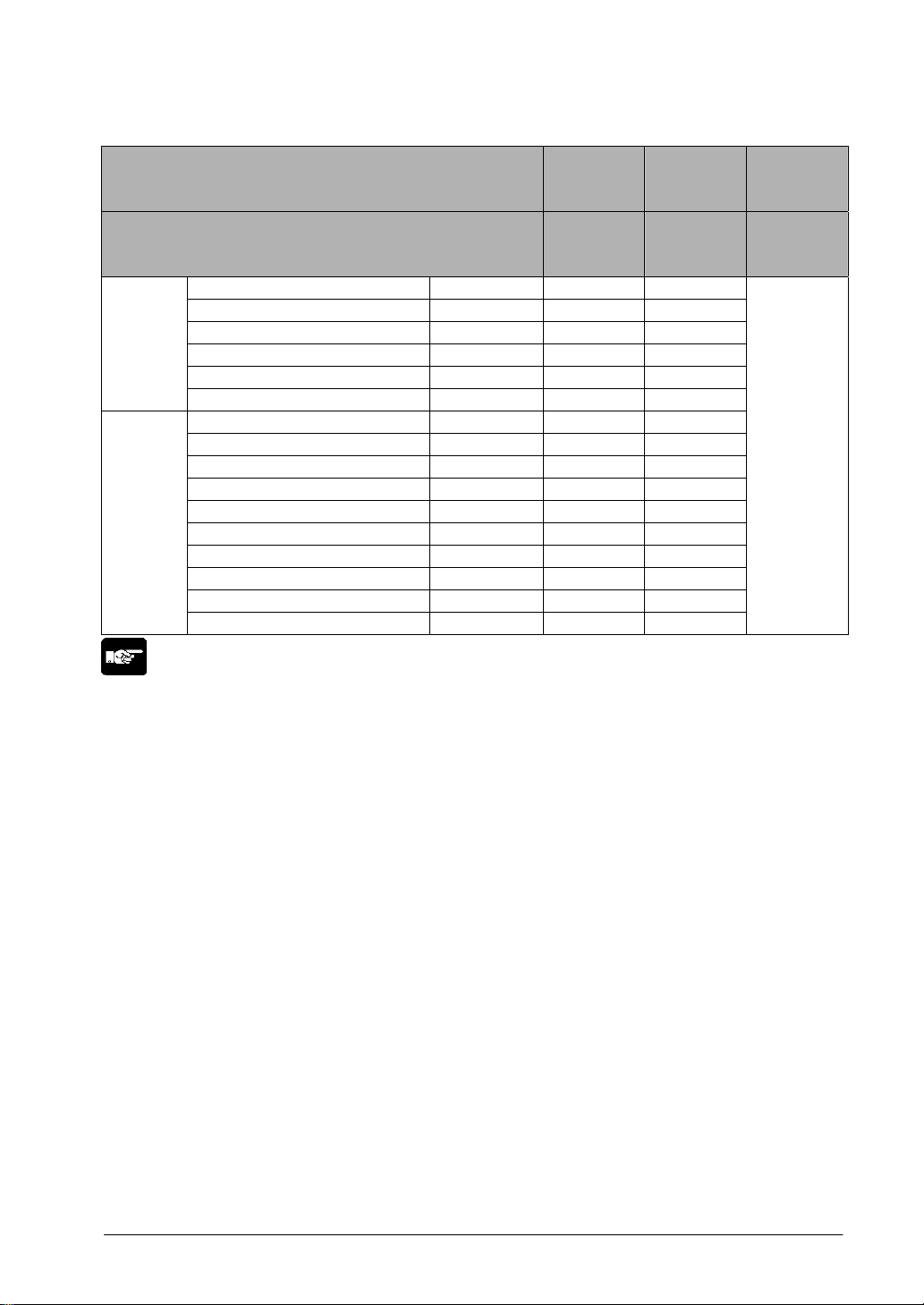
Programming Tool Restrictions
Restrictions on usable programming tools depending on the units (as of August, 2006)
Type of unit
Type of programming tool
AFPX-C14R
AFPX-C30R
AFPX-C60R
AFPX-C14T, C14TD, C14P, C14PD
AFPX-C30T, C30TD, C30P, C30PD
AFPX-C60T, C60TD, C60P, C60PD
FPWIN GR Ver.2
Used
(Ver. 2.5 or later)
Used
(Ver. 2.70 or later)
Windows software
FPWIN GR Ver.1 Not used Not used
Windows software
Conforms to
IEC61131-3
FPWIN Pro
Ver.5
Used
(Ver. 5.1 or later)
Used
(Ver. 5.22 or later)
NPST-GR Ver.4 Not used Not used
MS-DOS software
NPST-GR Ver.3 Not used Not used
AFP1113V2
AFP1114V2
Not used Not used
AFP1113
AFP1114
Not used Not used
Handy programming
unit
AFP1111A
AFP1112A
AFP1111
AFP1112
Not used Not used
FP memory loader
AFP8670
AFP8671
Used
(Only porgrams and system registers can be transmitted.)
Note: Precautions concerning version upgrade
• In case of using FPWIN GR Ver.1, please purchase upgrade model FPWIN GR Ver.2.
• FPWIN GR Ver. 2.0 can be upgraded to Ver. 2.5 or later free of charge at our web site
(
http://www.nais-e.com/plc/).
• In case of using FPW
IN Pro Ver.4, please purchase upgrade model FPWIN Pro Ver.5.
• FPWIN Pro Ver. 5.0 can be free of charge at our web site (
http://www.nais-e.com/plc/).
• The handy
programmign unit cannot be used.
Do not download any programs for other units such as FP1 to the FP-X using the handy programming
unit .
CTi Automation - Phone: 800.894.0412 - Fax: 208.368.0415 - Web: www.ctiautomation.net - Email: info@ctiautomation.net

Chapter 1
Features, Functions and Restrictions
CTi Automation - Phone: 800.894.0412 - Fax: 208.368.0415 - Web: www.ctiautomation.net - Email: info@ctiautomation.net

1-2
1.1 Features and Functions of the Unit
Features
• Compact size general-purpose PLC that is suitable for the small-scale facility control.
• Can be directly connected to a personal computer using USB communication port.
• High demensional security functions to deal with copying programs.
• Supports analog control.
• Following items are provided as options,
- Application cassettes, such as the positioning control function by the high-speed counter and
pulse output.
- Fulfilling communication cassettes.
- Realtime clock function.
Basic functions as compact size general-purpose PLC suitable for the small-scale facility control
Basic functions including the followings are equipped even though it is a general-pur pose sytle such as
AC power supply, screw terminal block and relay output.
1. 32k-step program capacity
2. 0.32 μs command processing speed
3. Max. 382-points I/O control
Single-phase 8-channel and 2-phase 4 channel high-speed counter functions are equipped for
the control unit.
Fulfilling function enhancement
Various add-on cassettes are available as options (such as 10 types of application cassettes and
6 types of communication cassette).
• Application cassettes
DC 8-point input type, transistor 8-point NPN output type, transistor 6-point PNP output type, DC 4-point
input + transistor 3-point NPN output type, analog 2-ch output type, analog 2-ch input + analog 1-ch
output type, thermocouple 2-ch type, analog 2-ch input type, high-speed counter input + pulse output
type, master memory type with realtime clock (32k-step program can be copied and stored.)
• Communication cassettes
1-ch RS232C type, 2-ch RS232C type, 1-ch RS485/RS422 changeover type, 1-ch RS232C + 1-ch
RS485 type, Ethernet + 1-ch RS232C type, 2-ch RS485 type
FP0 expansion units can be connected as well as the exclusive expansio n unit.
A maximum of 3 FP0 expansion units can be connected using the expansion FP0 adapter.
A personal computer can be directly connected with the USB communication port.
A personal computer can be directly connected with the USB cable (excluding C14).
The USB⇔RS232C conversion adapter/cable is not necessary.
(A tool port (RS232C) is also equipped.)
CTi Automation - Phone: 800.894.0412 - Fax: 208.368.0415 - Web: www.ctiautomation.net - Email: info@ctiautomation.net

1-3
High demensional security functions to deal with copying programs.
The uploading disabling function prohibits uploading (readin g) programs in the PLC main unit and
prevent illegal copying.
(It also enables to transfer the programs to the FP-X master memory cassette, when the uploading
disabling function is specified).
The protection for programs can be selected from
3 security methods.
• 4-digit password
• 8-digit password
• Uploading disabling
A full range of communication functions
Using the Tool port (RS232C) provided as a standard feature on the main unit, communication can be
carried out with a display panel or computer. Additionally, communication cassettes with RS232C,
RS485 and Ethernet interfaces are available as an option. Installing a 2-channel RS232C type
communication cassette in the FP-X makes it possible to connect two devices with RS232C port. A full
lineup of communication functions means you can also work with 1:N communication (up to 99 units)
and PC(PLC) link function (up to 16 units).
Controlling two devices with RS232C port with one FP-X
When using the 2-channel RS232C type communication cassette
1:N communication possible with up to 99 stations (units)
When using the 1-channel RS485/RS422 type communication cassette
When using the 1-channel RS485 and 1-channel RS232C in combination
Link with FP2 and FPΣ is possible
Data sharing between small size and medium size PLCs is easily achievable in one network.
The FP-X supports MEWNET-W0, and the programless PLC link with the FP2 or FP Σ is possible.
CTi Automation - Phone: 800.894.0412 - Fax: 208.368.0415 - Web: www.ctiautomation.net - Email: info@ctiautomation.net

1-4
Supports Modbus RTU
It can be used as a master unit/slave units (F145 and F146 instructions).
It can be easily communicated with a temperature control device, inverter, FP-e or overseas PLCs.
It is possible to communicate with up to 99 units
MEWTOCOL communication
It can be used as a master unit/slave units (F145 and F146 instructions).
It can be easily communicated with a PLC, image processor, temperature control device, message
runner or eco-power meter.
It is possible to communicate with up to 99 units
CTi Automation - Phone: 800.894.0412 - Fax: 208.368.0415 - Web: www.ctiautomation.net - Email: info@ctiautomation.net
1-5
Positioning control supported through high-speed counter and pulse output
With the FP-X Tr type, a high-speed counter function can be used by using the CPU I/O.
With the FP-X Ry type, a high-speed counter and pulse output functions can be used by using the pulse
I/O cassette. The pulse output function supports frequencies of up to 100kHz, enabling positioning
control using a stepping motor or servo motor.
Note) The pulse I/O cassette cannot be used for the FP-X Tr type.
Measurement using high-speed counter supported
Increment input mode, decrement input mode, 2-phase input mode, individual input mode, and direction
discrimination mode are supported.
Note) Differs depending on combinations.
Positioning control based on pulse output supported
Pulse/direction and clockwise/counter –clockwise output are supporte d.
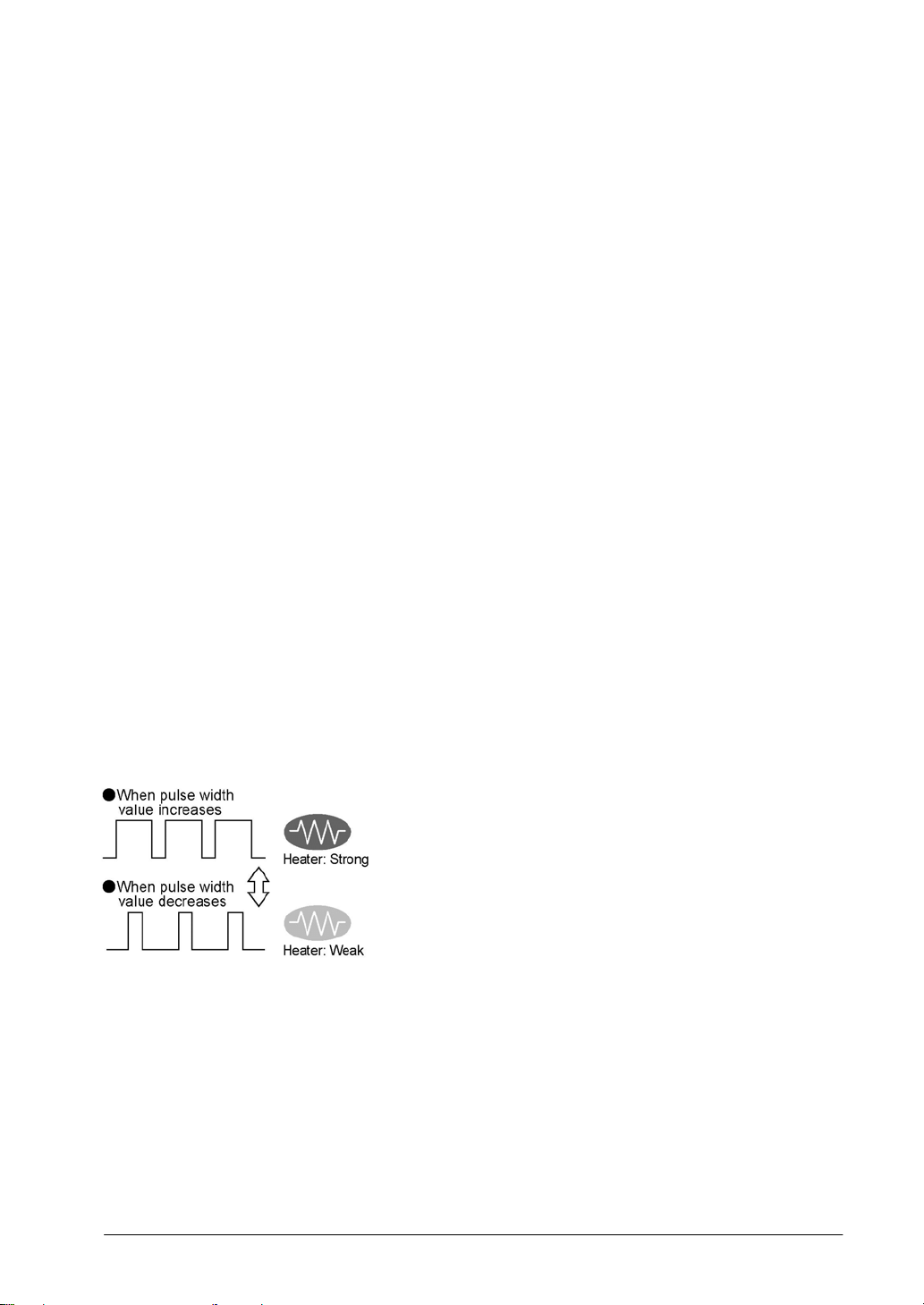
Heater control based on PWM output function supported
The pulse output at any duty ratio can be picked up with special instruction.
Analog potentionmeter (volume dial)
An analog potentionmeter (volume dial) is provided as a standard feature. This can be used in
applications such as analog timers, without using the programming tools.
Realtime clock function can be added
Optional FP-X master memory cassette (AFPX-MRTC) and backup battery enables the realtime clock
function.
CTi Automation - Phone: 800.894.0412 - Fax: 208.368.0415 - Web: www.ctiautomation.net - Email: info@ctiautomation.net
1-6
1.2 Unit Types
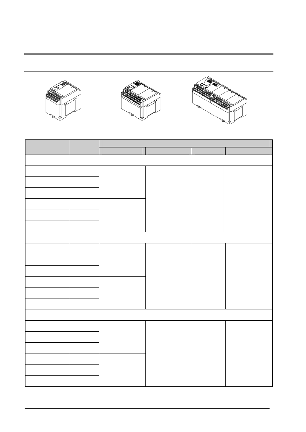
1.2.1 FP-X Control Units
C14 C30 C60
Specifications
Product No.
No. of I/O
points
Power supply Input Output Connection
Relay type (Ry type)
AFPX-C14R 8/6
AFPX-C30R 16/14
AFPX-C60R 32/28
100 to 240 V AC
AFPX-C14RD 8/6
AFPX-C30RD 16/14
AFPX-C60RD 32/28
24 V DC
24 V DC
(Common
polarities
+ & - common)
Relay Terminal block
Transistor type (NPN) (Tr type)
AFPX-C14T 8/6
AFPX-C30T 16/14
AFPX-C60T 32/28
100 to 240 V AC
AFPX-C14TD 8/6
AFPX-C30TD 16/14
AFPX-C60TD 32/28
24V DC
24 V DC
(Common
polarities
+ & - common)
Transistor
(NPN)
Terminal block
Transistor type (PNP) (Tr type)
AFPX-C14P 8/6
AFPX-C30P 16/14
AFPX-C60P 32/28
100 to 240 V AC
AFPX-C14PD 8/6
AFPX-C30PD 16/14
AFPX-C60PD 32/28
24V DC
24 V DC
(Common
polarities
+ & - common)
Transistor
(PNP)
Terminal block
CTi Automation - Phone: 800.894.0412 - Fax: 208.368.0415 - Web: www.ctiautomation.net - Email: info@ctiautomation.net
1-7
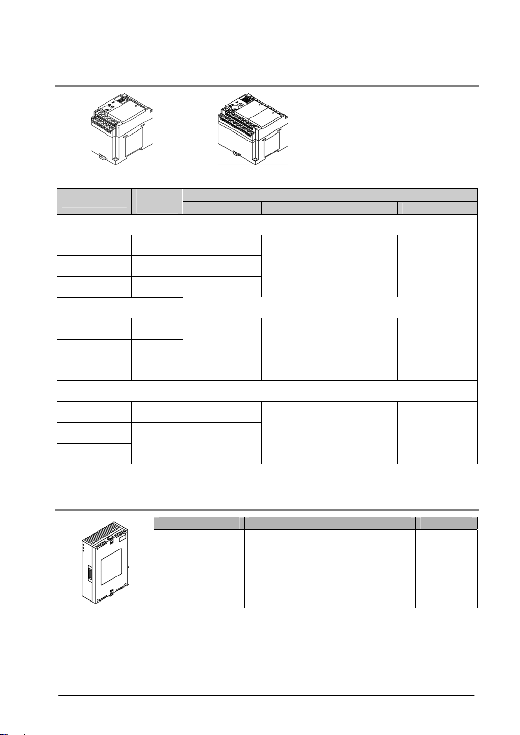
1.2.2 FP-X Expansion Unit
E16 E30
Specifications
Product No.
No. of I/O
points
Power supply Input Output Connection
Relay type (Ry type)
AFPX-E16R 8/8 -
AFPX-E30R 16/14 100 to 240 V AC
AFPX-E30RD 16/14 24 V DC
24 V DC
(Common
polarities
+ & - common)
Relay Terminal block
Transistor type (NPN) (Tr type)
AFPX-E16T 8/8 -
AFPX-E30T 100 to 240 V AC
AFPX-E30TD
16/14
24V DC
24 V DC
(Common
polarities
+ & - common)
Transistor
(NPN)
Terminal block
Transistor type (PNP) (Tr type)
AFPX-E16P 8/8 -
AFPX-E30P 100 to 240 V AC
AFPX-E30PD
16/14
24V DC
24 V DC
(Common
polarities
+ & - common)
Transistor
(PNP)
Terminal block
An 8-cm expansion cable is provided with anxpansion unit
1.2.3 FP-X Expansion FP0 Adapter
Name Specifications Product No.
FP-X Expansion
FP0 adapter (with 8
cm expansion
cable, power supply
cable)
For connecting FP0 expansion unit AFPX-EFP0
CTi Automation - Phone: 800.894.0412 - Fax: 208.368.0415 - Web: www.ctiautomation.net - Email: info@ctiautomation.net
1-8
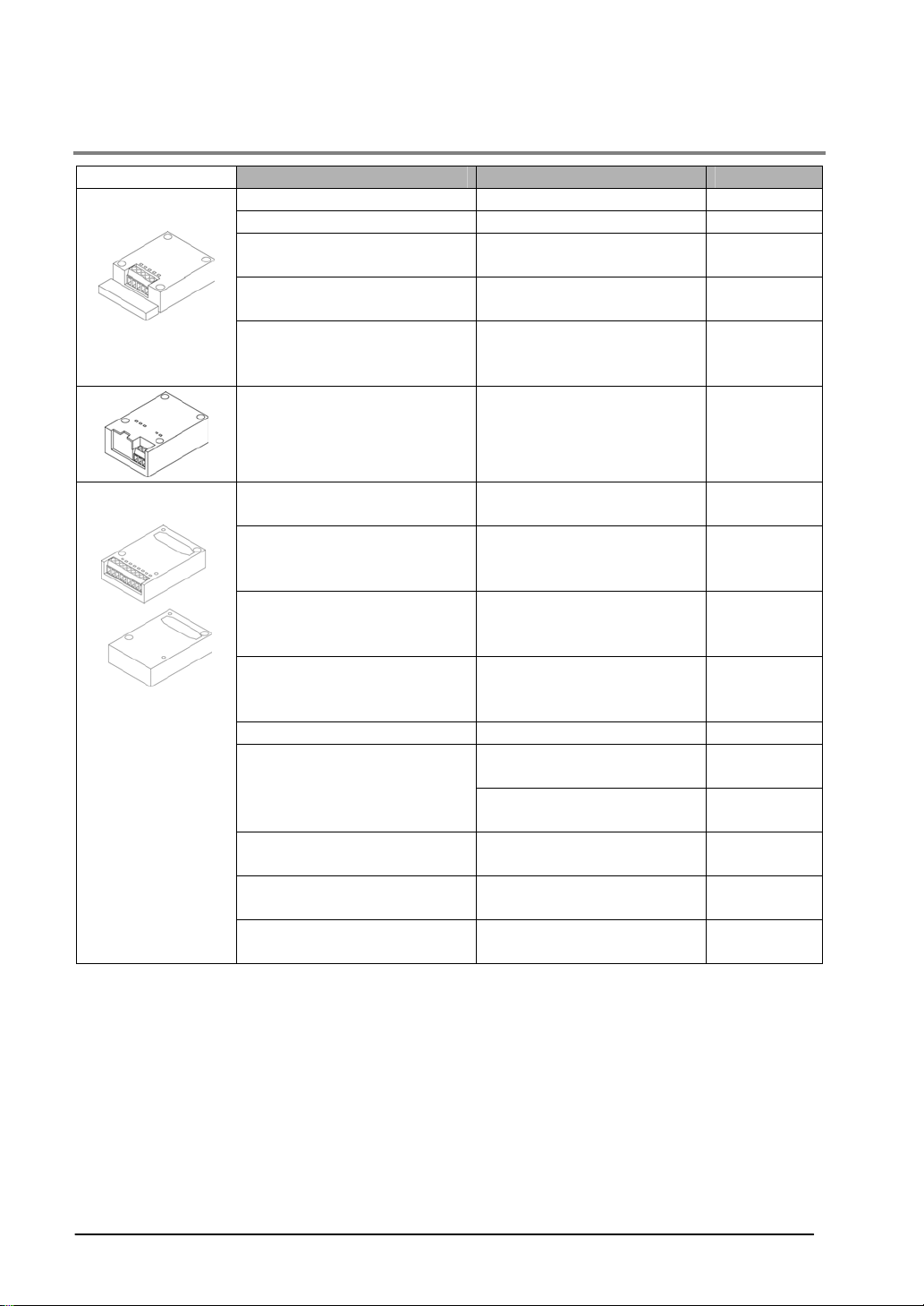
1.2.4 Add-on Cassettes (Communication cassettes/Application cassettes)
Name Specifications Product No.
FP-X Communication cassette 5-wire 1-channel RS232C AFPX-COM1
FP-X Communication cassette 3-wire 2-channel RS232C AFPX-COM2
FP-X Communication cassette
1-channel RS485/RS422
(insulated)
AFPX-COM3
FP-X Communication cassette
1-channel RS485 (insulated)
3-wire 1-channel RS232C
AFPX-COM4
Communication
cassette
FP-X Communication cassette
2-channel RS485
(non-insulated between
channels)
AFPX-COM6
FP-X Communication cassette
Ethernet,
3-wire 1-channel RS232C
AFPX-COM5
FP-X Analog input cassette
2-channel analog input
(non-insulated)
AFPX-AD2
FP-X Analog output cassette
2-channel analog output
(insulated) (non-insulated
between channels)
AFPX-DA2
FP-X Analog I/O cassette
2-channel analog input
(insulated) + 1-channel
analog output (insulated)
AFPX-A21
FP-X Thermocouple cassette
2-channel thermocouple input
(insulated) (non-insulated
between channels)
AFPX-TC2
FP-X Input cassette 8-point DC input AFPX-IN8
8-point transistor output
(NPN)
AFPX-TR8
FP-X Output cassette
6-point transistor output
(PNP)
AFPX-TR6P
FP-X I/O cassette
4-point DC input + 3-point
transistor output (NPN)
AFPX-IN4T3
FP-X Pulse I/O cassette
2-ch high-speed counter +
1-ch pulse output
AFPX-PLS
Application
cassette
FP-X Master memory cassette
Master memory + realtime
clock
AFPX-MRTC
CTi Automation - Phone: 800.894.0412 - Fax: 208.368.0415 - Web: www.ctiautomation.net - Email: info@ctiautomation.net
1-9
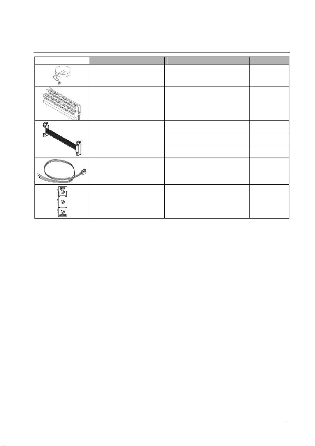
1.2.5 Related Parts
Name Description Product No.
FP-X Backup battery
Necessary fro the backup of
data registers, etc. or for using
the realtime clock function.
AFPX-BATT
FP-X terminal block
(C30/C60)
For C30/C60 control unit
for E30 expansion I/O unit
with 21-pin cover (no printing)
4 pcs/pack
AFPX-TAN1
8 cm AFPX-EC08
30 cm AFPX-EC30
FP-X expansion cable
Note)
80 cm AFPX-EC80
FP0 power supply cable
For Expansion FP0 adapter,
Length: 1 m
AFP0581
FP0 mounting plate
(slim type)
Used for expansion FP0
adapter and FP0 Expansion
unit, 10 pcs/pack
AFP0803
Note) The total length of the exapansion cable should be within 160 cm.
CTi Automation - Phone: 800.894.0412 - Fax: 208.368.0415 - Web: www.ctiautomation.net - Email: info@ctiautomation.net

1-10
1.3 Restrictions on Unit Combinations
1.3.1 Restrictions on FP-X Expansion Unit
Controllable I/O points
Type of control unit
Number of I/O points when
using control unit
Number of I/O points when
using 8 units of E30
expansion I/O unit
FP-X C14 Control unit 14 points Max. 254 points
FP-X C30 Control unit 30 points Max. 270 points
FP-X C60 Control unit 60 points Max. 300 points
Note:
- Up to eight units of FP-X can be connected, however, the restrictions on each expansion unit vary.
- For AFPX-E16: Two units cannot be connected consecutively since the power should be supplied from
the unit with the power supply (as no power supply is built in AFPX-E16).
E16 expansion I/O unit cannot be connected on the right side of the control unit or AFPX-E30.
- For AFPX-E30: There is no restriction on AFPX-E30 so that up to 8 units can be connected
consecutively.
- The total length of the expansion cable should be within 160 cm.
CTi Automation - Phone: 800.894.0412 - Fax: 208.368.0415 - Web: www.ctiautomation.net - Email: info@ctiautomation.net
1-11
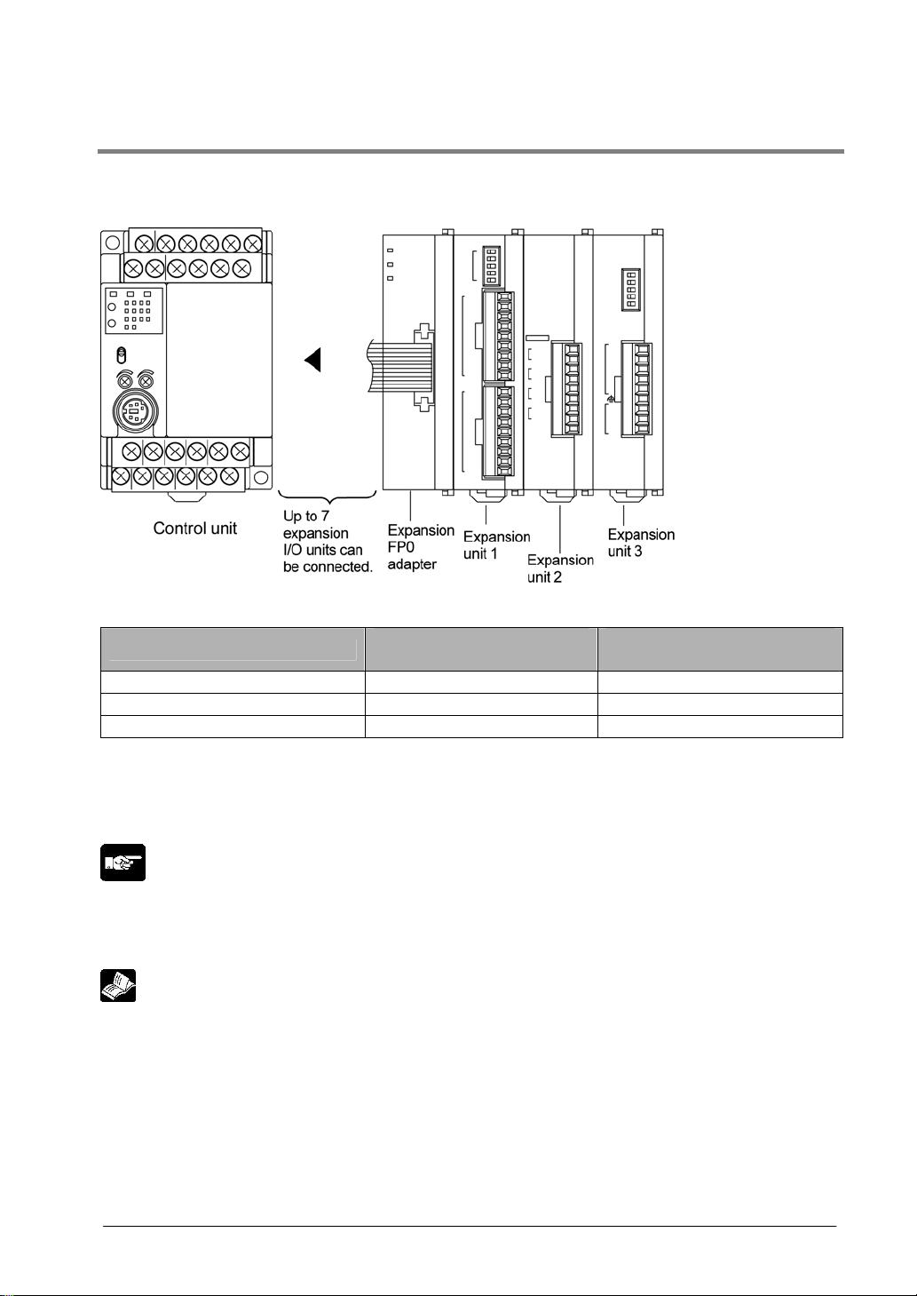
1.3.2 Restrictions on FP0 Expansion Unit
Up to three dedicated FP0 expansion units can be added using the FP- X and the expansion FP0 adapter.
The relay output type and the transistor output type can be used in combination.
Controllable I/O points
Type of control unit
Number of I/O points when
using control unit
Number of I/O points when
using FP0 expansion unit
FP-X C14 Control unit 14 points Max. 110 points
FP-X C30 Control unit 30 points Max. 126 points
FP-X C60 Control unit 60 points Max. 156 points
Note1) Up to seven FP-X expansion I/O units can be also installed between the control unit and the
expansion FP0 adapter.
Note2) Only one expansion FP0 adapter can be installed at the last position of the FP-X expansion bus.
(It should be installed at the right hand side of the AFPX-E16 and E30.)
Note:
• Install the FP0 thermocouple unit on the right side of other expansion units. If it is installed on the left
side, the total precision will deteriorate.
• Install the FP0 CC-Link slave unit on the right side of the other expansion units. There is no expansion
connector on the right side.
Reference: For the details, <FP0 Thermocouple Unit Manual ARCT1F366E>
<FP0 CC-Link Slave Unit Manual ARCT1F380E>
CTi Automation - Phone: 800.894.0412 - Fax: 208.368.0415 - Web: www.ctiautomation.net - Email: info@ctiautomation.net

1-12
1.3.3 Restrictions on FP-X Add-on Cassette
The add-on cassette is installed in the cassette mounting part 1 and 2 (only the cassette mounting part 1
is available for C14) of the control unit.
CTi Automation - Phone: 800.894.0412 - Fax: 208.368.0415 - Web: www.ctiautomation.net - Email: info@ctiautomation.net
1-13
A: Available, N/A: Not available
Restrictions on control unit
FP-X C14
FP-X C30
FP-X C60
FP-X C30
FP-X C60
FP-X C60
Type of add-on cassette
Cassette
mounting
part 1
Cassette
mounting
part 2
Expansion
connector
part
FP-X Communication cassette AFPX-COM1 A N/A
FP-X Communication cassette AFPX-COM2 A N/A
FP-X Communication cassette AFPX-COM3 A N/A
FP-X Communication cassette AFPX-COM4 A N/A
FP-X Communication cassette AFPX-COM5 A N/A
Commu-
nication
cassette
FP-X Communication cassette AFPX-COM6 A N/A
FP-X Analog input cassette AFPX-AD2 A A
FP-X Input cassette AFPX-IN8 A A
FP-X Analog output cassette AFPX-DA2 A A
FP-X Analog I/O cassette AFPX-A21 A A
FP-X Thermocouple cassette AFPX-TC2 A A
FP-X Output cassette AFPX-TR8 A A
FP-X Output cassette AFPX-TR6P A A
FP-X I/O cassette AFPX-IN4T3 A A
FP-X Pulse I/O cassette AFPX-PLS A
Note5)
A
Note5)
Appli-
cation
cassette
FP-X Master memory cassette AFPX-MTRC A
Note1)
A
Note1)
The add-on
cassette
cannot be
installed.
Note:
1. Only one FP-X master memory cassette AFPX-MRTC can be installed. If 2 units are installed, E26
(user ROM error) will occur.
2. One application cassette can be installed in either cassette mounting part 1 or 2 of C30/C60.
3. As only one communication cassette can be installed in the cassette mounting part 1, it should be
installed on on the application cassette if the application cassette is installed. (It cannot be installed in
the cassette mounting part 2.)
4. The add-on cassette cannot be installed in the expansion connector part of C60 (it does not work).
5. The pulse I/O cassette cannot be installed on the FP-X Tr type.
CTi Automation - Phone: 800.894.0412 - Fax: 208.368.0415 - Web: www.ctiautomation.net - Email: info@ctiautomation.net
1-14
1.4 Programming Tools
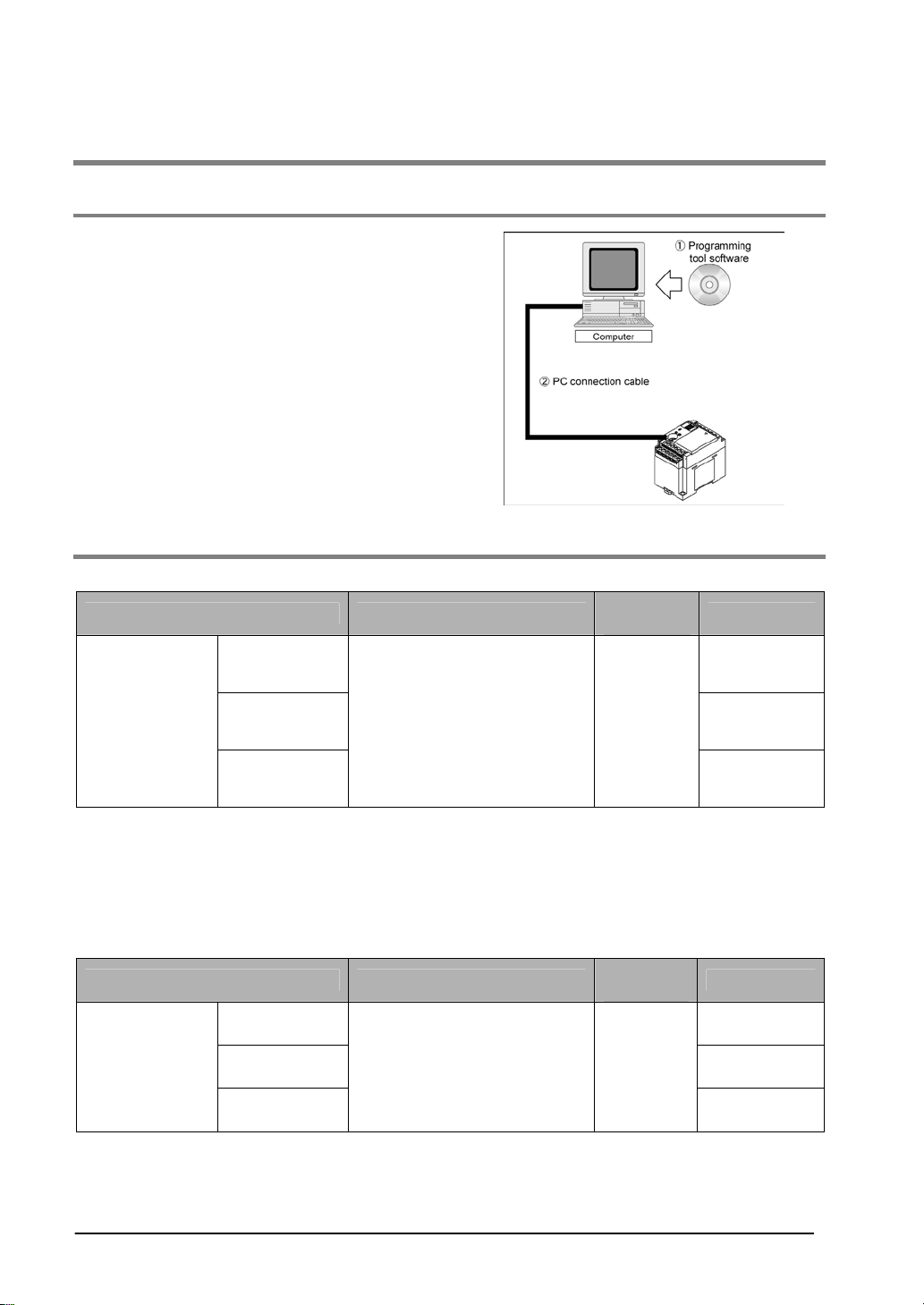
1.4.1 Tools Needed for Programming
1. Programming tool software
• The tool software can also be used with the FP
series.
• “FPWIN Pro Ver.5” or “FPWIN GR Ver.2”
Windows sorware is used with FP-X.
FPWIN GR Ver.1x, NPST-GR and FP
Programmer cannot be used.
2. PC connection cable
• The connection cable for DOS/V machine is
available.
• A commercial USB cable can be used for the
connection for C30/C60 control unit.
1.4.2 Software Environment and Suitable Cable
Standard ladder diagram tool software FPWIN-GR Ver.2
Type of software OS (Operating system)
Hard disk
capacity
Product No.
Full type AFPS10520
Small type AFPS11520
FPWIN GR Ver.2
English-
language menu
Upgrade
version
Windows®95 (OSR 2 or later)
Windows®98
Windows®Me
WindowsNT® (Ver. 4 or later)
Windows®2000
Windows®XP
40MB or
more
AFPS10520R
Note1) Ver.1.1 must be installed to install the upgrade version.
Note2) Ver.2.0 can be upgraded to the latest version after Ver. 2.1 free of charge at our web site
(http://www.mew.co.jp/ac/e/). Use the latest version.
Note3) The small type can be used only for each series of FP-e, FPΣ, FP0, FP-X, FP1 and FP-M.
Note4) A USB cable cannot be used when using Windows®95.
Conforms to IEC61131-3 programming tool software FPWIN-Pro Ver.5
Type of software OS (Operating system)
Hard disk
capacity
Product No.
Full type AFPS50550
Small type AFPS51550
FPWIN Pro
Ver.5
English-
language menu
Upgrade
version
Windows®95 (OSR 2 or later)
Windows®98
Windows®Me
WindowsNT® (Ver. 4 or later)
Windows®2000
Windows®XP
100MB or
more
AFPS50550R
Note1) The small type can be used only for each series of FP-e, FPΣ, FP0, FP-X, FP1 and FP-M.
Note2) Ver.4 must be installed to install the upgrade version.
Note3) Ver.5.0 can be upgraded to the latest version after Ver. 5.1 free of charge at our web site
(
http://www.mew.co.jp/ac/e/). Use the latest version.
CTi Automation - Phone: 800.894.0412 - Fax: 208.368.0415 - Web: www.ctiautomation.net - Email: info@ctiautomation.net

1-15
Type of computer and suitable cable
For the connection between a personal computer (RS232C) and the control unit (RS232C)
PC side connector PLC side connector Specifications Product No.
female-Mini DIN round 5-pin L type (3 m) AFC8503
D-sub 9-pin
female-Mini DIN round 5-pin Straight type (3 m) AFC8503S
Note) A USB/RS232C conversion cable is necessary to connect with a personal computer without a
serial port using a PC connection cable.
For the connection between a personal computer (USB) and the control unit (USB)
USB cable (For C30 and C60 only)
Use a commercial cable.
Cable type Length
USB 2.0 (or 1.1) AB type Max. 5 m
Reference: <Chapter 6 Tool Port and USB Port>
CTi Automation - Phone: 800.894.0412 - Fax: 208.368.0415 - Web: www.ctiautomation.net - Email: info@ctiautomation.net

1-16
CTi Automation - Phone: 800.894.0412 - Fax: 208.368.0415 - Web: www.ctiautomation.net - Email: info@ctiautomation.net
Loading...