


Order No: PAPAMY1501049CE
Installation Manual
OFF/ON
|
|
|
|
|
|
|
|
|
|
|
|
|
|
|
|
|
|
|
|
|
|
|
|
|
|
|
|
|
|
|
|
|
|
|
|
|
|
|
|
|
|
|
|
|
|
|
|
|
|
|
|
|
|
|
|
|
|
|
|
|
|
|
|
|
|
|
|
|
|
|
|
|
|
|
|
|
|
|
|
|
|
|
|
|
|
|
|
|
|
AUTO |
|
|
|
FAN |
|
|
|
|
|
|
|
HEAT |
|
|
|
SPEED |
|
|
|
|
|
|
|
COOL |
|
|
|
|
|
|
|
|
|
|
|
DRY |
|
|
|
AIR |
|
|
|
|
|
|
|
FAN |
|
|
|
SWING |
|
|
|
|
|
|
|
|
|
|
|
|
|
OFF/ON |
AUTO |
|
COMFORT |
Indoor Unit |
Outdoor Unit |
CS-E9RKUAW |
CU-E9RKUA |
CS-E12RKUAW |
CU-E12RKUA |
CS-E18RKUAW CU-E18RKUA CS-E24RKUAW CU-E24RKUA
Destination
USA
Canada
POWERFUL/ |
AIR SWING |
QUIET FAN SPEED |
Please file and use this manual together with the service manual for Model No. CU-2E18NBU and CU-5E36QBU, Order No. PHAAM1111120A1 and PAPAMY1312037CE.
 WARNING
This service information is designed for experienced repair technicians only and is not designed for use by the general public.
It does not contain warnings or cautions to advise non-technical individuals of potential dangers in attempting to service a product. Products powered by electricity should be serviced or repaired only by experienced professional technicians. Any attempt to service or repair the products dealt with in this service information by anyone else could result in serious injury or death.
 PRECAUTION OF LOW TEMPERATURE
In order to avoid frostbite, be assured of no refrigerant leakage during the installation or repairing of refrigerant circuit.
© Panasonic Corporation 2015.
11. Installation Instruction (E9RK and E12RK)
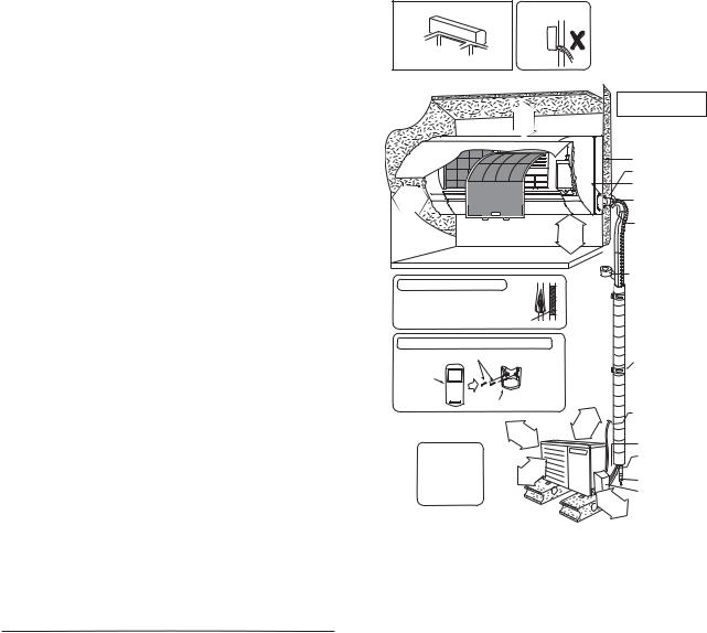
11.1Select the Best Location
11.1.1Indoor Unit
Do not install the unit in excessive oil fume area such as kitchen, workshop and etc.
There should not be any heat source or steam near the unit.
There should not be any obstacles blocking the air circulation.
A place where air circulation in the room is good.
A place where drainage can be easily done.
A place where noise prevention is taken into consideration.
Do not install the unit near the door way.
Ensure the spaces indicated by arrows from the wall, ceiling, fence or other obstacles.
Recommended installation height for indoor unit shall be at least 8 ft (2.4 m).
11.1.2Outdoor Unit
If an awning is built over the unit to prevent direct sunlight or rain, be careful that heat radiation from the condenser is not obstructed.
There should not be any animal or plant which could be affected by hot air discharged.
Keep the spaces indicated by arrows from wall, ceiling, fence or other obstacles.
Do not place any obstacles which may cause a short circuit of the discharged air.
If piping length is over the [piping length for additional gas], additional refrigerant should be added as shown in the table.
Recommended installation height for outdoor unit should be above the seasonal snow level.
|
|
Piping size |
|
|
Min. |
Max. |
|
Piping |
||
|
Capacity |
|
|
Std. |
Max. |
Piping |
Additional |
Length |
||
Model |
|
|
Piping |
|||||||
(Btu/h) |
Gas |
Liquid |
Length |
Elevation |
Length |
Refrigerant |
for add. |
|||
|
Length |
|||||||||
|
|
|
|
|
|
|
|
|
gas |
|
E9RKUAW |
9000 |
3/8" |
|
|
|
|
|
|
|
|
(9.52 mm) |
1/4" |
24.6 ft |
49.2 ft |
9.8 ft |
65.6 ft |
0.2 oz/ft |
24.6 ft |
|||
|
|
|||||||||
E12RKUAW |
11500 |
1/2" |
(6.35 mm) |
(7.5 m) |
(15 m) |
(3 m) |
(20 m) |
(20 g/m) |
(7.5 m) |
|
(12.7 mm) |
|
|
|
|
|
|
|
|||
|
|
|
|
|
|
|
|
|
||
Example: For E9RKUAW
If the unit is installed at 32.8 ft (10 m) distance, the quantity of additional refrigerant should be 1.64 oz (50 g) .... (32.8 - 24.6) ft x 0.2 oz/ft = 1.64 oz.
((10 -7.5) m x 20 g/m = 50 g).
11.1.3Indoor/Outdoor Unit Installation Diagram
Piping direction |
|
Do not bend up |
|
(Front side) |
drain hose |
Right |
|
|
Rear |
Left |
|
Right Left |
|
|
bottom Rear |
Left bottom |
|
|
Installation parts you |
|
/"916 |
should purchase (Ú) |
|
)mm reo 65( mor |
||
2 |
 1 31/32"
 (50 mm) or more
(Left and right are identical) |
)m ore 4.(2 m |
|
t or f |
|
8 |
Floor / Grade level
Installation plate 1 |
Bushing-Sleeve (Ú) |
Sleeve (Ú) |
Putty (Ú) |
(Gum Type Sealer) |
Bend the pipe as closely on the wall as possible, but be careful that it doesn’t break.
Insulation of piping connections
• Carry out insulation after |
|
checking for gas leaks and |
|
secure with vinyl tape. |
Ú Vinyl tape |
Attaching the remote control holder to the wall
Remote control holder fixing screws 6
Remote control 3
Remote control holder 5
( |
3 |
1 |
|
|
|
|
|
||
|
|
|
5 |
|
|
|
|
||
1 |
|
|
|
/ |
|
|
|
||
|
0 |
|
|
|
1 |
|
|
||
o |
|
0 |
m |
6" |
|
||||
r |
m |
|
|
|
|||||
|
|
|
|
m) |
|
||||
|
|
|
or |
|
|
|
|
||
It is advisable to |
|
|
|
|
e |
|
|
|
|
avoid more than 2 |
|
|
|
|
|
|
|
|
|
blockage directions. |
|
|
|
|
|
|
|
" |
) |
|
|
|
|
|
|
/8 |
|||
For better ventilation |
|
|
|
|
|
3 |
m |
||
|
|
|
|
9 |
m e |
||||
|
|
|
|
3 |
|
|
0 |
r |
|
& multiple-outdoor |
|
|
|
|
|
|
0 |
o |
|
|
|
|
|
0 |
|
|
|||
|
|
|
(1 rm |
||||||
installation, please |
|
|
|
|
|
|
o |
|
|
|
|
|
|
|
|
|
|
|
|
consult authorized |
|
|
|
|
|
|
|
|
|
dealer/specialist. |
|
|
|
|
|
|
|
|
|
•This illustration is for explanation purposes only.
The indoor unit will actually face a different way.
3
1 5
/ (1
 Vinyl tape (wide) (Ú)
• Apply after carrying out a drainage test.
•To carry out the drainage test,
remove the air filters and pour water into the heat exchanger.
|
|
|
|
|
|
|
|
Saddle (Ú) |
1 |
6 |
|
" |
|
m |
) |
|
Conduit |
|
|
m |
r e |
(Power supply cord (Ú)) |
||||
|
0 |
|
o |
|||||
0 |
|
|
m |
|||||
|
|
r |
|
Conduit |
||||
|
|
o |
|
|
||||
|
|
|
|
|
|
|||
|
|
|
|
|
|
|
||
|
|
|
|
|
|
|
|
(Connection cable) |
|
|
|
|
|
|
|
|
Liquid side piping (Ú) |

 Gas side piping (Ú)
|
11 |
|
Additional drain hose (Ú) |
|
( |
|
Control Board cover |
||
1 |
|
|
|
|
3 |
|
3 |
|
|
0 |
/ |
|
||
o |
0 |
1 |
|
|
r |
|
|
6 |
|
mm |
|
" |
||
|
o m |
|
||
|
r |
) |
||
|
e |
|
|
|
33
11.2Indoor Unit
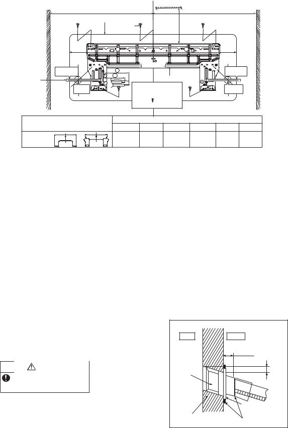
11.2.1How to Fix Installation Plate
The mounting wall shall be strong and solid enough to prevent it from the vibration.
Wall |
|
|
|
|
|
Wall |
|
|
Wall |
|
|
|
More than 1 |
|
|
|
More than 1 |
||||
|
|
|
|
|
|
|
||||
|
|
|
Indoor unit |
|
More than |
|
|
|
||
|
|
|
2 screw |
|
|
2 |
|
|
|
|
|
|
|
3 |
|
|
4 |
|
|
|
|
|
|
|
|
|
5 1/16" (128 mm) |
|
|
|
||
|
9 17/32" |
|
6 |
|
|
|
|
9 17/32" |
||
|
(241.5 mm) |
|
5 |
|
|
|
|
(241.5 mm) |
||
Measuring |
|
|
|
Installation plate 1 |
|
|
|
|||
|
|
|
|
|
|
|
||||
|
|
|
|
|
|
|
|
|
||
Tape |
5 |
1/16" |
|
For best strength of |
|
5 1/16" |
|
|||
|
|
INDOOR unit installation, |
|
|
||||||
|
(128 mm) |
|
|
(128 mm) |
||||||
|
|
|
|
it is highly recommended |
|
|
|
|||
|
|
|
|
to locate “ ” at 5 position |
|
|
|
|||
|
|
|
|
as shown. |
|
|
|
|
||
|
Model |
|
|
|
|
Dimension |
|
|
||
|
|
1 |
|
2 |
3 |
4 |
5 |
6 |
||
|
|
|
|
|||||||
E9RKUAW, |
or |
19 9/32" |
3 7/32" |
17 9/32" |
17" |
1 11/16" |
3 3/4" |
|||
E12RKUAW |
(490 mm) |
(82 mm) |
(439 mm) |
(432 mm) |
(43 mm) |
(95 mm) |
||||
|
|
|||||||||
The center of installation plate should be at more than c at right and left of the wall.
The distance from installation plate edge to ceiling should more than d.
From installation plate left edge to unit’s left side is e.
From installation plate right edge to unit’s right side is f.
B: For left side piping, piping connection for liquid should be about g from this line. : For left side piping, piping connection for gas should be about h from this line.
1Mount the installation plate on the wall with 5 screws or more (at least 5 screws). (If mounting the unit on the concrete wall, consider using anchor bolts.)
o Always mount the installation plate horizontally by aligning the marking-off line with the thread and using a level gauge.
2Drill the piping plate hole with ø2 3/4" (ø70 mm) hole-core drill.
o Line according to the left and right side of the installation plate. The meeting point of the extended line is the center of the hole. Another method is by putting measuring tape at position as shown in the diagram above. The hole center is obtained by measuring the distance namely 5 1/16" (128 mm) for left and right hole respectively.
o Drill the piping hole at either the right or the left and the hole should be slightly slanting to the outdoor side.
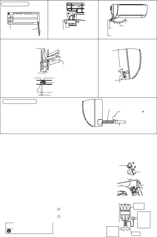
11.2.2 |
To Drill a Hole in the Wall and |
|
|
|
Install a Sleeve of Piping |
|
Wall |
1 Insert the piping sleeve to the hole. |
|
||
|
|
||
2 Fix the bushing to the sleeve. |
Indoor |
Outdoor |
|
3 Cut the sleeve until it extrudes about 19/32" |
|
|
|
|
(15 mm) from the wall. |
|
19/32" (15 mm) |
|
|
Sleeve for |
|
|
CAUTION |
tube |
|
|
|
assembly |
|
|
When the wall is hollow, please be sure |
|
|
|
to use the sleeve for tube assembly to |
|
Approx. 7/32" - 9/32" |
|
prevent dangers caused by mice biting |
|
|
|
|
(5-7 mm) |
|
|
the connection cable. |
|
|
|
|
|
|
4 Finish by sealing the sleeve with putty or |
|
Bushing for tube |
|
|
caulking compound at the final stage. |
|
assembly |
|
|
|
|
|
|
ø2 3/4" (ø70 mm) |
Putty or caulking compound |
|
|
through hole |
|
34

11.2.3Indoor Unit Installation
Do not turn over the unit without it’s shock absorber during pull out the piping. It may cause intake grille damage.
Use shock absorber during pull out the piping to protect the intake grille from damage.
pull out the
pi pi n g
Piping
Intake grille
11.2.3.1For the right rear piping
Step-1 Pull out the Indoor piping
Step-2 Install the Indoor Unit
Step-3 Secure the Indoor Unit
Step-4 Insert the connection cable
11.2.3.2For the right bottom piping
Step-1 Pull out the Indoor piping
Step-2 Install the Indoor Unit
Step-3 Insert the connection cable
Step-4 Secure the Indoor Unit
11.2.3.3For the embedded piping
Step-1 Replace the drain hose
Step-2 Bend the embedded piping
•Use a spring bender or equivalent to bend the piping so that the piping is not crushed.
Step-3 Pull the connection cable into Indoor Unit
•The inside and outside connection cable can be connected without removing the front grille.
Step-4 Cut and flare the embedded piping
•When determining the dimensions of the piping, slide the unit all the way to the left on the installation plate.
•Refer to the section “Cutting and flaring the piping”.
Step-5 Install the Indoor Unit
Step-6 Connect the piping
•Please refer to “Connecting the piping” column in outdoor unit section. (Below steps are done after connecting the outdoor piping and gas-leakage confirmation.)
Step-7 Insulate and finish the piping
•Please refer to “Insulation of piping connection” column as mentioned in indoor/outdoor unit installation.
Step-8 Secure the Indoor Unit
pull ou
t the
pi pi n g
Piping |
Shock absorber
Right Rear piping
Tape it with piping in a position as
mentioned in Fig. below.
Piping
Drain |
Cover for the |
hose |
|
|
bottom piping |
How to keep the cover
In case of the cover is cut, keep the cover at the rear of chassis as shown in the illustration for future reinstallation.
(Left and 2 bottom covers for piping.)
Right and Right Bottom piping
Cover
Cover for the |
for the |
bottom piping left |
|
|
piping |
Cover for piping
Tape it with piping in a position as mentioned in Fig. below.
Piping
Cover for Drain hose the right
piping
Install the indoor unit
Hook the indoor unit onto the upper portion of installation plate. (Engage the indoor unit with the upper edge of the installation plate). Ensure the hooks are properly seated on the installation plate by moving it in left and right.
Secure the Indoor Unit
1.Press the lower left and right side of the unit against the installation plate until hooks engages with their slot (sound click).
Cover for the |
Cover for |
|
the left |
||
bottom piping |
||
piping |
||
|
||
|
Hooks at |
|
|
installation |
|
|
plate |
|
|
Sleeve for |
|
|
piping hole |
|
|
Piping |
Indoor unit
Drain hose
Unit’s |
Installation |
|
plate |
||
hook |
||
|
|
|
|
|
|
|
|
|
|
To take out the unit, push the |
|
|
|
|
|
|
|
|
|
|
marking at the bottom unit, and pull it |
|
|
|
|
|
|
|
|
|
|
slightly towards you to disengage the |
|
|
|
|
|
|
|
|
marking |
|
hooks from the unit. |
|
|
|
|
|
|
|
|
|
|
|
|
Insert the connection cable |
|
|||||||||
23 |
|
|
b |
|
|
Connection |
|
|||
|
|
|
|
cable |
|
|||||
( |
|
|
|
A |
|
|
|
|
Gas side |
|
|
4 |
|
o |
|
|
|||||
7 |
/ |
|
|
u |
|
|
|
|||
|
|
" |
|
|
|
|
|
|||
0 |
|
- |
|
|
t |
|
|
piping |
||
- |
|
3 |
|
|
|
|
||||
|
8 |
|
|
|
|
|
||||
|
|
0 |
|
5 |
|
|
|
|
||
|
|
|
|
|
/ |
" |
|
|
Liquid side |
|
|
|
|
mm |
|
|
|
||||
|
|
|
|
|
|
3 |
|
|
|
|
|
|
|
|
|
|
2 |
|
|
|
|
|
|
|
|
|
) |
|
|
|
piping |
|
|
|
|
|
|
|
|
|
|
|
|
|
|
|
|
|
|
|
|
Guide |
Connection cable |
Drain hose |
|
|
|
|
|
|
|
|
surface |
||
|
|
|
|
|
|
|
|
|
|
|
(This can be used for left rear piping and bottom piping also.)
35
Replace the drain hose
Rear view for left piping installation
Drain hose
Drain cap |
Drain hose |
Connection |
|
|
cable |
Adjust the piping slightly downwards.
• How to pull the piping and drain hose out, in case of embedded piping.
|
|
|
|
|
|
|
|
|
|
|
|
) |
|
|
|
|
|
|
|
|
|
n |
|
|
m |
Apply putty or |
|
|
|
|
|
|
|
|
|
m |
||
|
|
|
|
tha |
|
0 |
|
|||||
caulking material |
|
ore |
|
|
|
"(95 |
|
|||||
|
|
|
2 |
|
|
|
||||||
|
|
|
M |
|
3/3 |
|
|
|
|
|||
to seal the wall |
|
|
|
1 |
|
|
|
|
|
|
|
|
|
|
3 |
|
|
|
|
|
|
|
|
||
|
|
|
|
7 |
|
|
|
|
|
|
Connection |
|
opening. |
|
|
|
|
|
|
|
|
|
|
||
|
|
|
|
|
|
|
|
|
|
cable |
||
|
/16" |
|
|
|
|
|
|
|
|
|
||
|
|
|
|
|
|
|
|
|
|
|
Piping |
|
|
9 |
|
|
|
|
|
|
|
|
|
|
|
|
27 |
|
|
|
|
|
|
|
an |
|
|
|
|
|
|
|
|
|
|
|
|
|
|
|
|
|
|
|
|
|
|
|
th |
|
|
|
||
|
|
|
|
|
re |
|
|
|
) |
|
||
|
than |
mm) |
|
o |
|
|
|
|
|
from main unit |
||
|
|
1/2" |
|
|
|
m |
||||||
|
|
|
|
M |
|
|
|
|
|
Drain hose |
||
|
|
|
|
|
|
|
|
|
70m |
|
|
|
|
|
|
18 |
|
|
(4 |
|
|
|
|||
|
More |
(700 |
|
|
|
|
|
|
|
|
||
|
PVC tube (VP-65) for piping |
|||||||||||
PVC tube for |
and connection cable |
|||||||||||
|
|
PVC tube for drain hose (VP-30) |
||||||||||
drain hose (VP-20) |
|
|||||||||||
PVC tube |
|
|
|
|
|
Cable |
|
|
|
|||
for drain |
|
|
|
|
|
|
|
|
|
|
|
|
hose |
|
|
|
|
|
Piping |
|
|
||||
|
|
|
|
|
|
|
|
|||||
Indoor unit
3 15/16" (100 mm)
Drain hose adapter 9 usage
•Join indoor drain hose to 3/4" (20 mm) nominal PVC pipe size by using drain hose adapter 9 when necessary.
Remarks :
Make sure indoor unit drain hose & 3/4" (20 mm) nominal PVC pipe are fully inserted to drain hose adapter 9.
|
Connection |
|
Piping |
cable |
|
More than 37 13/32" |
||
|
||
Drain hose |
(950 mm) |
Sleeve for piping hole
•How to insert the connection cable and drain hose in the case of left piping.
° 5 4
Drain 
 hose
hose
Cable
Piping
(For right piping, follow the same procedure)
Indoor unit drain hose
Close join by Vinyl Tape ( )
 Drain hose adapter 9
3/4" (20 mm) nominal PVC pipe
-Install incline downward more than 1°
-Apply PVC glue at the join.
11.2.4Connect the Cable to the Indoor Unit
1.The inside and outside connection cable can be connected without removing the front grille.
2.Unscrew the conduit cover and fix the conduit connector to conduit cover with lock nut, then secure it against chassis.
3.Connection cable between indoor unit and outdoor unit should be UL listed or CSA approved 4 conductor wires minimum AWG16 in accordance with local electric codes.
4.Connection cable between indoor unit and outdoor unit should be UL listed or CSA approved 4 conductor wires minimum AWG16 in accordance with local electric codes.
o Ensure the colour of wires of outdoor unit and terminal number are the same as the indoor's repectively.
Terminals on the indoor unit |
|
1 |
|
|
2 |
|
3 |
|
|
|
|
|
|
|
|
|
|
|
|
|
|
||||
|
|
|
|
|
|
|
|
|
|
|
|
|
Colour of wires (connection cable) |
|
|
|
|
|
|
|
|
|
|
|
|
Terminals on the outdoor unit |
|
1 |
|
|
2 |
|
3 |
|
|
|
|
|
|
|
|
|
|
|
|
|
|
||||
|
|
|
|
|
|
|
|
|
|
|
|
|
 WARNING
This equipment must be properly earthed.
oEarth lead wire shall be Yellow/Green (Y/G) in colour and shall be longer than other lead wires as shown in the figure for electrical safety in case of the slipping.
Conduit
Connector
Conduit
Cover
Lock Nut 

Chassis
Rear Side of Indoor Unit
1 |
2 |
3 |
Indoor and 

 outdoor
 connection
cable
Terminal
Board
Earth Wire longer than others AC wires for safety reason
Holder
36
11.2.5Wiring Stripping and connecting requirement
|
|
|
Wire stripping |
Conductor |
Conductor |
Conductor not |
|
|
|
|
|||
|
13/32" ± 1/16" |
(10±1 mm) |
Indoor/outdoor |
fully inserted |
over inserted |
fully inserted |
|
connection |
|
|
|
||
|
terminal board |
|
|
|
||
|
7/32" (5 mm) |
|
|
|
||
No loose strand |
or more |
ACCEPT |
PROHIBITED |
PROHIBITED |
||
when inserted |
|
|
(gap between wires) |
RISK OF FIRE |
|
JOINING OF WIRES |
|
MAY CAUSE |
OR |
WARNING OVERHEATING |
|
AND FIRE. |
|
Do not joint wires |
|
OR |
OR |
 Use complete wire without joining.
 Use approved socket and plug with earth pin.
Wire connection in this area must follow to national wiring rules.
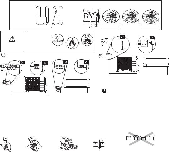
11.2.5.1Cutting and flaring the piping
1Please cut using pipe cutter and then remove the burrs.
2Remove the burrs by using reamer. If burrs are not removed, gas leakage may be caused. Turn the piping end down to avoid the metal powder entering the pipe.
3Please make flare after inserting the flare nut onto the copper pipes.
|
Pipe |
|
Handle |
0 – 1/32" |
|
Reamer |
|
(0-0.5 mm) |
|
|
|
|
||
|
Bar |
Yoke |
Bar |
|
|
|
|||
|
|
|
|
|
|
|
|
Core |
|
|
Point down |
Clamp handle |
Red arrow mark |
Copper |
|
|
pipe |
||
1 . To cut |
|
|
|
|
2. To remove burrs |
3. To flare |
|
||
Improper flaring
Inclined Surface Cracked Uneven damaged thickness
When properly flared, the internal surface of the flare will evenly shine and be of even thickness. Since the flare part comes into contact with the connections, carefully check the flare finish.
37
 Loading...