


CS-A24CTP
8 Operating Instructions
■ Installation Precautions
!
Warning
● This room air conditioner must be
earthed.
Improper grounding could cause
electric shock.
● Ensure that the drainage piping is
connected properly.
Otherwise, water will leak out.
● Do not install the unit in a
potentially explosive atmosphere.
Gas leak near the unit could cause
fire.
● Do not install, remove and reinstall the unit by
yourself.
Improper installation will cause leakage, electric
shock or fire. Please engage an authorized dealer
or specialist for the installation work.
!
Caution
O
F
F
O
F
F
■ Operation Precautions
!
Warning
This sign warns of death or serious injury.
● Do not share outlet.
● Do not insert plug to operate the unit. Do not
pull out plug to stop the unit.
● Do not operate with wet hands.
● Do not damage or modify the power cord.
● Do not insert finger or other objects into the
indoor or outdoor units.
●
Do not expose directly to cold air for a long period.
● Plug in properly.
● Use specified power cord.
● If abnormal condition (burnt smell, etc.)
occurs, switch off and unplug the power
supply.
!
Caution
This sign warns of injury.
● Do not pull the cord to disconnect the plug.
● Do not wash the unit with water.
● Do not use for other purposes such as
preservation.
● Do not use any combustible equipment at
airflow direction.
●
Do not sit or place anything on the indoor or
outdoor unit.
● Switch off the power supply before cleaning.
● Ventilate the room regularly.
● Pay attention as to whether the installation
rack is damaged after long period of usage.
● Switch off the power supply if the unit is not
used for a long period.
SAFETY PRECAUTIONS
Before operating, please read the following
“Safety Precautions” carefully.
● To prevent personal injury, injury to others and
property damage, the following instructions must be
followed.
● Incorrect operation due to failure to follow instructions
will cause harm or damage, the seriousness of which
is classified as follow:
!
Warning
This sign warns of death or serious injury.
!
Caution
This sign warns of damage to property.
● The instructions to be followed are classified by the
following symbols:
This symbol (with a white background) denotes an
action that is PROHIBITED.
These symbols (with a black background) denote
actions that are COMPULSORY.
O
F
F
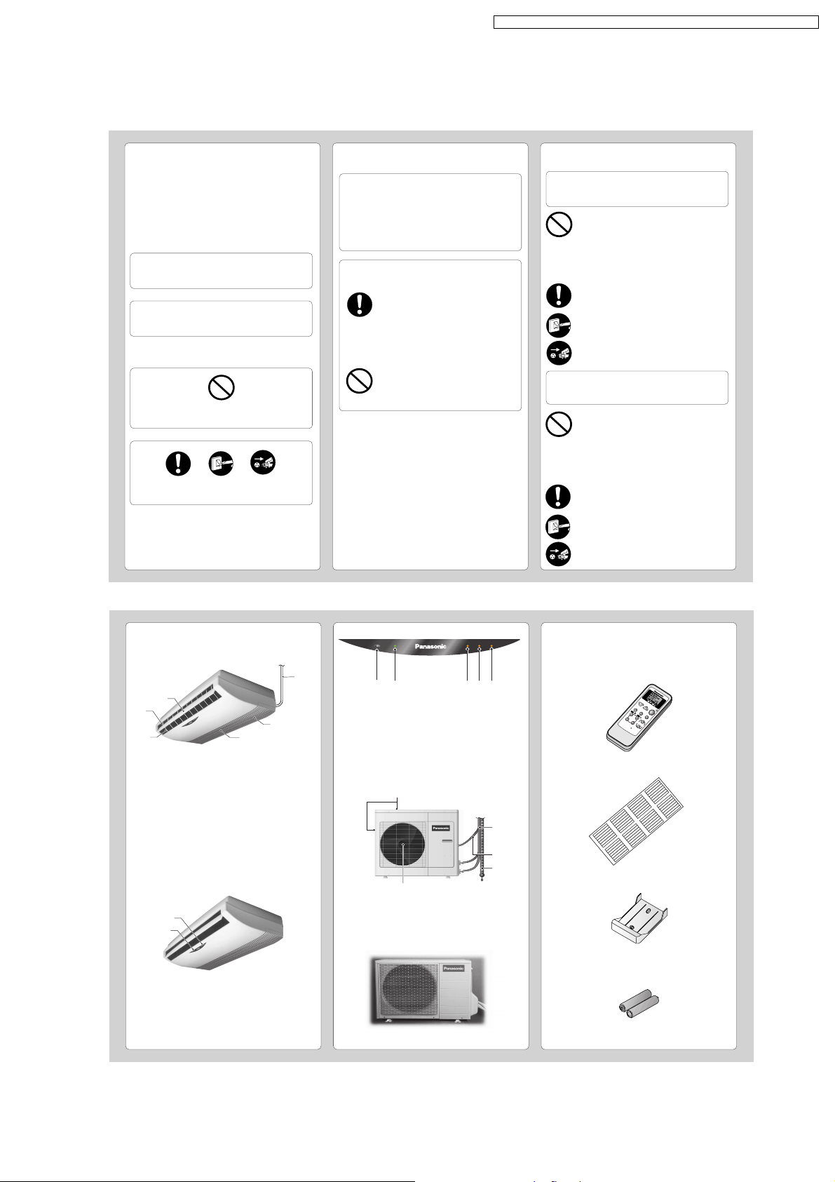
NAME OF EACH PART
■ Indoor Unit
1 Air Outlet Vent
2 Power Supply Cord
3 Air Intake Vent
4 Air Filters (behind the panel)
5 Horizontal Airflow Direction Louver
(manually adjusted)
6 Vertical Airflow Direction Louver
● Indoor Unit Controls
1 Operation Indication Lamps
2 Signal Receptor
1 Auto Operation Button
2 Power Mode Indicator – GREEN
3 Timer Mode Indicator – ORANGE
4 Sleep Mode Indicator – ORANGE
5 Air Swing Mode Indicator – ORANGE
■ Outdoor Unit
■ Accessories
● Remote Control
● Remote Control Indication Sticker
● Remote Control Holder
● Two RO3 (AAA) dry-cell batteries or equivalent
O
F
F
/
O
N
T
E
M
P
M
O
D
E
F
AN
S
P
E
E
D
A
U
T
O
T
I
M
E
R
A
IR
S
W
IN
G
R
E
S
E
T
S
LE
EP
M
A
N
U
A
L
S
E
L
E
C
T
S
E
T
/
C
A
N
C
E
L
A
B
A
U
T
AUT
O
H
E
A
HEA
T
C
O
O
L
COOL
D
R
DR
Y
FA
N
AN
S
P
E
E
D
SPEED
H
H
A
B
O
F
F
O
F
F
O
N
O
N
AUTO OFF/ON POWER TIMER SLEEP AIR SWING
1
2 3 4 5
1
2
3
4
1
2
3
1
6
5
2
CU-V18CTP5, CU-V24CTP5
CU-A18CTP5, CU-A24CTP5
1 Air Intake Vents
2 Piping
3 Connecting Cable
4 Air Outlet Vents
5 Drain Hose
4
5
CU-V12CTP5
CU-A12CTP5
35
CS-A12CTP CU-A12CTP5 / CS-A18CTP CU-A18CTP5 / CS-A24CTP CU-A24CTP5
NAME OF EACH PART
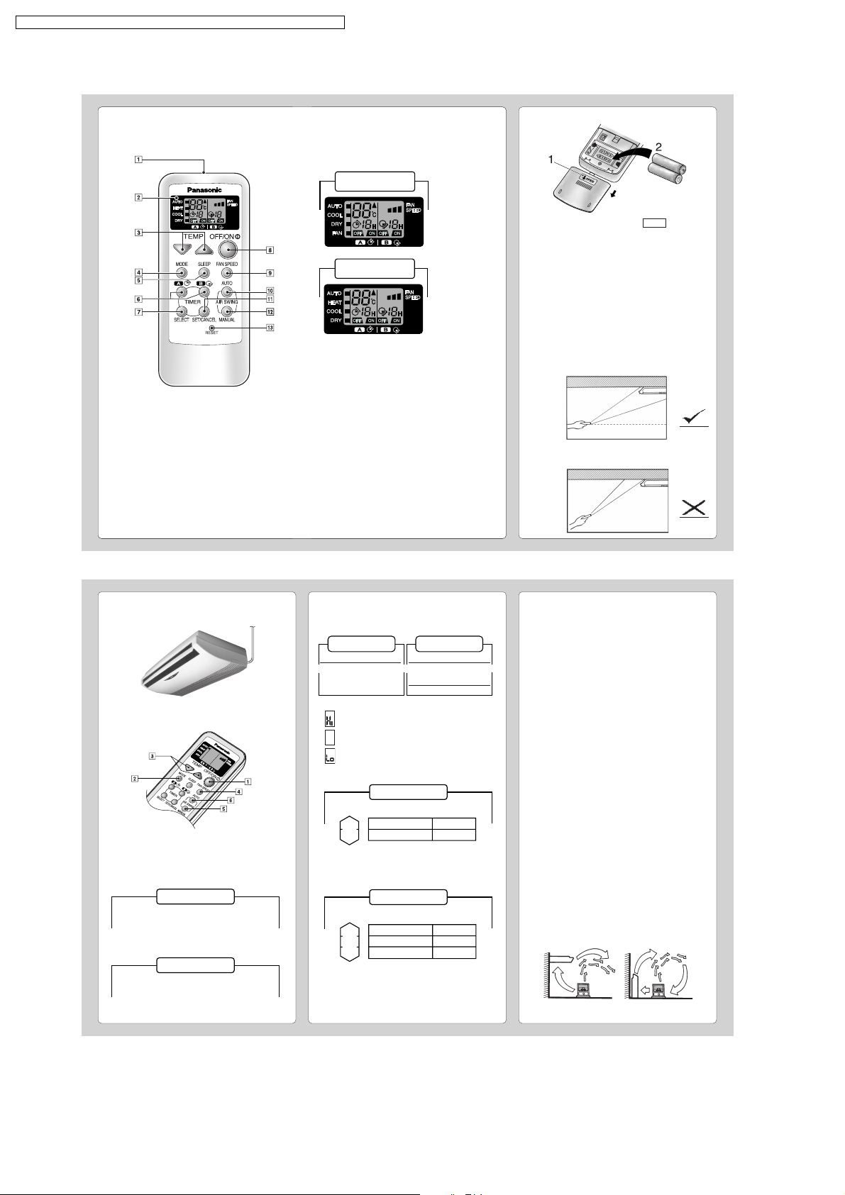
■ Remote Control
● Remote Control Signal.
• Make sure it is not obstructed.
• Maximum distance : 10 m.
• Signal received sound.
One short beep or one long beep.
● Notes for Remote Control.
• Do not throw or drop.
• Do not get it wet.
• Certain type of fluorescent lamps may affect
signal reception. Consult your dealer.
● Do not place the remote control in a location exposed
to direct sunlight, or next to a heating unit, or other
heat source.
● How to Insert the Batteries
1
Gently press the place marked OPEN and slide
the cover towards you.
2
Insert the batteries
– Be sure the direction is correct.
● About the batteries
• Can be used for approximately one year.
●
Observe the following when replacing the batteries
• Replace with new batteries of the same type.
• Do not use rechargeable batteries (Ni-Cd).
• Remove the batteries if the unit is not going to be
used for a long period.
● Proper way to operate the remote control in the
case of ceiling/wall mounting.
• Operate the remote control in parallel with the floor.
(See the figure below)
1 Signal Transmitter
2 Operation Display
3 Room Temperature Setting Button
(Illuminating button)
4 Operation Mode Selection Button
5 Sleep Mode Operation Button
(Illuminating button)
6 Timer Setting Button
7 Timer Selection Button
8 OFF/ON Button
(Illuminating button)
9 Fan Speed Selection Button
0 Auto Airflow Direction Button
! Timer Set/Cancel Button
@ Manual Airflow Direction Selection Button
# Reset Point
(Press with fine-tipped object to clear the memory)
Cooling Model
Heat Pump Model
HH
• The signal changes as shown in the figure below.
It means that the receiving conditions are bad and
the signal can not be controlled properly.
O.K.
OUT
(Fig. 2)
(Fig. 1) Horizontal Level
HOW TO OPERATE
■ To start the operation
• Press 1.
• POWER indicator (green) on the indoor unit will light up.
• To stop, press once more.
■ Setting Mode
• Press 2 to select:-
Cooling Model
AUTO – Automatic Operation
COOL – Cooling Operation
DRY – Soft Dry Operation
FAN – Air Circulation Operation
Heat Pump Model
AUTO – Automatic Operation
HEAT – Heating Operation
COOL – Cooling Operation
DRY – Soft Dry Operation
PREPARATION BEFORE OPERATION
■ Indoor Unit
1
Connect the power supply cord to an independent
power supply.
■ Setting Temperature
• Press 3 to increase or decrease the temperature.
• The temperature can be set between 16°C ~ 30°C
• Recommended temperature:
• During AUTO Operation, press 3 to select:-
• Operation with 2°C higher than the standard
temperature.
• Operation with the standard temperature.
• Operation with 2°C lower than the standard
temperature.
● Standard Temperature
Cooling Model
• Once the Automatic Operation is selected, the indoor
temperature sensor operates automatically to select
the desired operation mode with Cooling or Soft Dry.
• After the operation mode has been selected, the
mode does not change.
Heat Pump Model
• At the beginning of the automatic operation, Heating,
Cooling or Soft Dry is automatically selected according
to the indoor temperature.
• After the operation mode has been selected, the
mode does not change.
Operation
Cooling
Soft Dry
Standard
temperature
25°C
22°C
Indoor
temperature
23°C
Operation
Cooling
Soft Dry
Heating
Standard
temperature
25°C
22°C
21°C
Indoor
temperature
23°C
20°C
Cooling Model
COOL –> 26°C ~ 28°C
DRY –> 1°C ~ 2° C
lower than the
room temperature
Heat Pump Model
COOL –> 26°C ~ 28°C
DRY –> 1°C ~ 2° C
lower than the
room temperature
HEAT –>20°C ~ 24°C
● Operation Details
COOL – Cooling Operation
• To set the room temperature at your preference
cooling comfort.
AUTO – Automatic Operation
• Sense indoor temperature to select the optimum
mode.
• Temperature is not displayed on the remote control
during AUTO operation.
DRY – Soft Dry Operation
• A very gentle Cooling Operation, prior to
dehumidification. It does not lower the room
temperature.
• During Soft Dry operation, the indoor fan operates at
Low Fan Speed.
HEAT – Heating Operation
(for Heat Pump Model only)
• Heat is obtained from outdoor air to warm up the
room. When the outdoor ambient air temperature
falls, the heating capacity of the unit might be
reduced.
• Defrosting Operation
Depend on the outdoor temperature, the operation
occasionally stops to melt the frost on the outdoor
unit.
FAN – Air Circulation Operation
(for Cooling Model only)
• Heated air rises and collects at the top of the room.
The air circulation circulates the heated air downward,
thus increasing heating effectiveness. When the unit
is installed floor mounted, you should set the
temperature higher than that of ceiling mounted.
At ceiling mounted At floor mounted
1
36
CS-A12CTP CU-A12CTP5 / CS-A18CTP CU-A18CTP5 / CS-A24CTP CU-A24CTP5
 Loading...