


AJ-RC10G
Table of contents
 Loading...
/
/
/
G
Operating Instructions/Bedienungsanleitung
/
/
/
Mode d’emploi/Istruzioni per l’uso
Instrucciones de funcionamiento
操作手册/取扱説明書
Remote Control Unit/Fernsteuereinheit
Module de télécommande
Unità per il comando a distanza/Unidad de control remote
摄像机遥控器 / リモートコントロールユニット
Model No. AJ-
ENGLISHDEUTSCHFRANÇAISITALIANOESPAÑOL
Before operating this product, please read the instructions carefully and save this
manual for future use.
Bitte lesen Sie vor Inbetriebnahme dieses Produkts die Anleitungen sorgfältig durch
und bewahren Sie dieses Handbuch für spätere Verwendung auf.
Avant de vous servir de ce produit, veuillez lire attentivement les instructions et
enregistrer ce manuel pour une utilisation ultérieure.
Prima di utilizzare questo prodotto, leggere attentamente le istruzioni di questo
manuale e conservarlo per riferimento futuro.
Antes de poner este producto en funcionamiento, lea atentamente las instrucciones
y conserve este manual para uso futuro.
使用本产品前,请仔细阅读本说明书,并妥善保存以备日后参考。
お買い上げいただき、まことにありがとうございました。
この取扱説明書をよくお読みの上、正しくお使いください。
特に「安全上のご注意」は、ご使用前に必ずお読みいただき、安全にお使いください。
お読みになったあとは、保証書と一緒に大切に保管し、必要なときにお読みください。
F0706T0 -F @
Printed in Japan
VQT1A65
中
文
日
本
語
Read this first!
For General
DO NOT REMOVE PANEL COVERS
BY UNSCREWING THEM.
To reduce the risk of electric shock, do
not remove the covers. No user
serviceable parts inside.
Refer servicing to qualified service
personnel.
WARNING:
z TO REDUCE THE RISK OF FIRE OR
SHOCK HAZARD, DO NOT EXPOSE
THIS EQUIPMENT TO RAIN OR
MOISTURE.
z TO REDUCE THE RISK OF FIRE OR
SHOCK HAZARD, KEEP THIS
EQUIPMENT AWAY FROM ALL
LIQUIDS. USE AND STORE ONLY IN
LOCATIONS WHICH ARE NOT
EXPOSED TO THE RISK OF DRIPPING
OR SPLASHING LIQUIDS, AND DO
NOT PLACE ANY LIQUID CONTAINERS
ON TOP OF THE EQUIPMENT.
CAUTION:
TO REDUCE THE RISK OF FIRE OR
SHOCK HAZARD AND ANNOYING
INTERFERENCE, USE THE
RECOMMENDED ACCESSORIES ONLY.
CAUTION:
In order to maintain adequate ventilation,
do not install or place this unit in a
bookcase, built-in cabinet or any other
confined space. To prevent risk of
electric shock or fire hazard due to
overheating, ensure that curtains and any
other materials do not obstruct the
ventilation.
Note:
The rating plate is on the underside of the
unit.
E-1
indicates safety information.
Read this first! (Continued)
The lightni
d
For USA
CAUTION
RISK OF ELECTRIC SHOCK
DO NOT OPEN
CAUTION: TO REDUCE THE RISK OF
ELECTRIC SHOCK, DO NOT REMOVE COVER
NO USER SERVICEABLE PARTS INSIDE.
REFER TO SERVICING TO QUALIFIED
(OR BACK).
SERVICE PERSONNEL.
symbol, within an equilateral
triangle, is intended to alert the user
to the presence of uninsulated
“dangerous voltage” within the
product’s enclosure that may be of
sufficient magnitude to constitute a
risk of electric shock to persons.
The exclamation point within an
equilateral triangle is intended to
alert the user to the presence of
important operating and
maintenance (service) instructions in
the literature accompanying the
appliance.
ng flash with arrowhea
indicates safety information.
ENGLISH
FCC Note:
This equipment has been tested and found
to comply with the limits for a class A digital
device, pursuant to Part 15 of the FCC
Rules. These limits are designed to provide
reasonable protection against harmful
interference when the equipment is operated
in a commercial environment. This
equipment generates, uses, and can radiate
radio frequency energy, and if not installed
and used in accordance with the instruction
manual, may cause harmful interference to
radio communications. Operation of this
equipment in a residential area is likely to
cause harmful interference in which case the
user will be required to correct the
interference at his own expense.
Warning:
To assure continued FCC emission limit
compliance, the user must use only shielded
interface cables when connecting to external
units. Also, any unauthorized changes or
modifications to this equipment could void
the user’s authority to operate it.
E-2

Table of Contents
Read this first! ................................ 1
General............................................4
Features .......................................... 4
Accessories ....................................4
Connection......................................5
System configuration.....................5
Parts and functions........................ 6
Front panel ........................................6
Rear panel.......................................15
Basic operations ..........................16
When the power is on......................16
To enable the buttons/volumes .......16
To disable buttons/volumes.............16
Operation of the camera recorder ...17
Operation of the camera
using the unit volume ......................18
Operation of the scene file ..............19
Operation for recording ...................20
Saving/Loading of scene files onto
the SD memory card ....................21
Handling methods
for the SD memory card ..................21
To load data from the card ..............21
To write data on the card.................22
To delete files from the card............22
Initialization of the card....................22
Menu operation.............................23
Operations using the LCD panel .....23
Operation of the camera recorder
menu ...............................................23
Adjustment of functions
on the unit........................................23
Menu item ..................................... 24
Menu ...............................................24
BLACK.............................................24
FLARE.............................................25
GAMMA...........................................25
WHITE.............................................25
KNEE...............................................27
SHUTTER .......................................27
SHAD ..............................................28
MATRIX...........................................28
DTL..................................................29
SKIN DTL ........................................29
FUNC ..............................................30
SYSTEM..........................................31
Connection cable ......................... 32
Confirmation of software
version .......................................... 32
Specifications............................... 33
E-3
General
The AJ-RC10G (hereinafter called “the unit”) is a remote control unit connected to the camera recorder.
The unit controls the camera recorder from the controller and is capable of changing numerical values
in the menu. Coverage can be extended by 50m by using the dedicated cable.
Features
z For some frequently functions on the camera unit, dedicated switches are provided for direct
operation.
z By switching to the recorder mode, the camera recorder can be controlled directly through the VTR
operation switch. In addition, recording can be disabled using a switch.
z Frequently used menus can be set by accessing the menus on the LCD panel of the unit. It is also
possible to display the time code on the LCD panel.
z Down-converted images with characters are output from the VIDEO OUT connector. The menus can
be operated on the main unit of the camera recorder by connecting the external monitor.
z By switching to the scene file mode, it is possible to operate the scene file. Data of revised scene files
can be stored on an SD memory card.
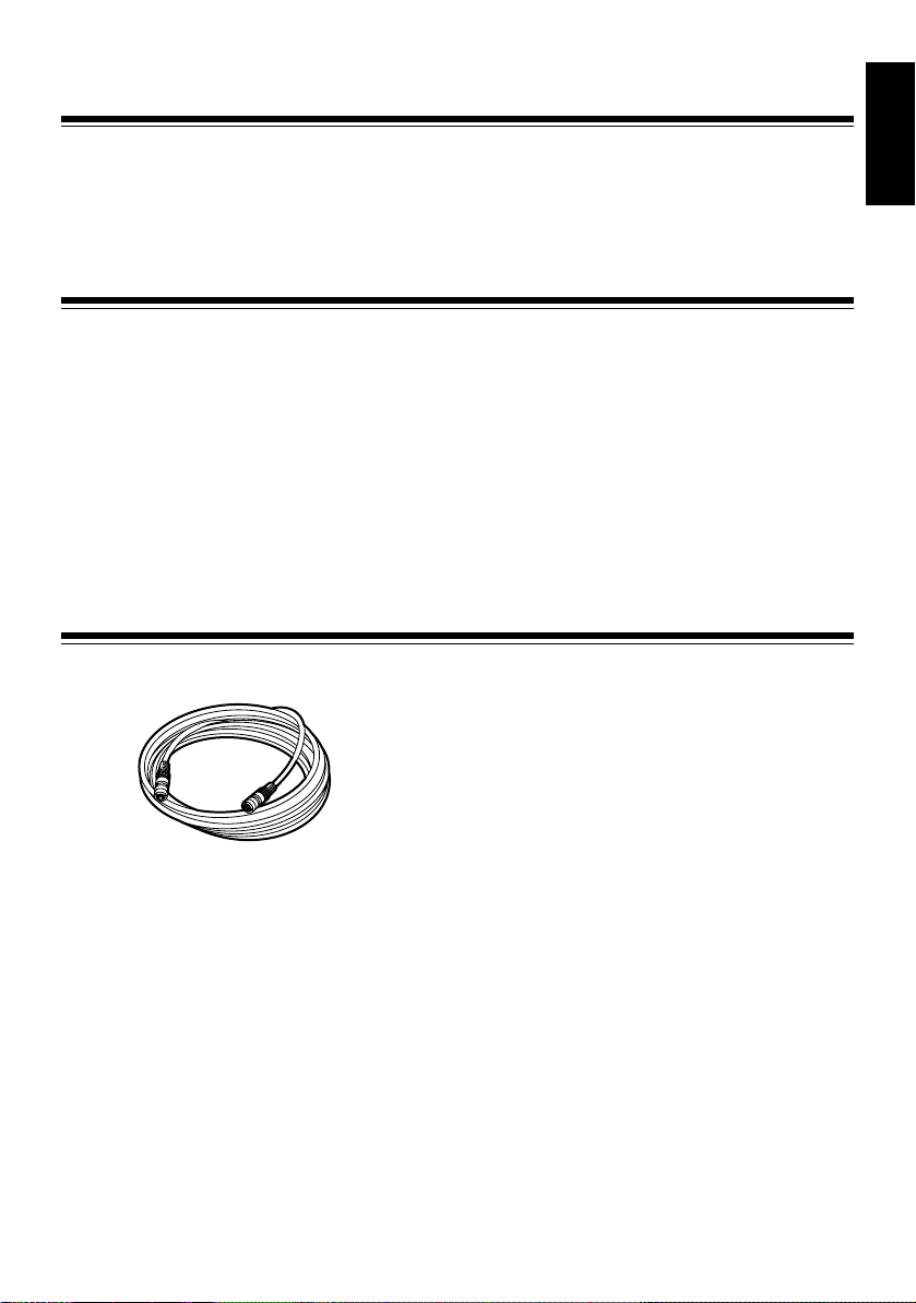
Accessories
Connection cable (10 m)
ENGLISH
E-4
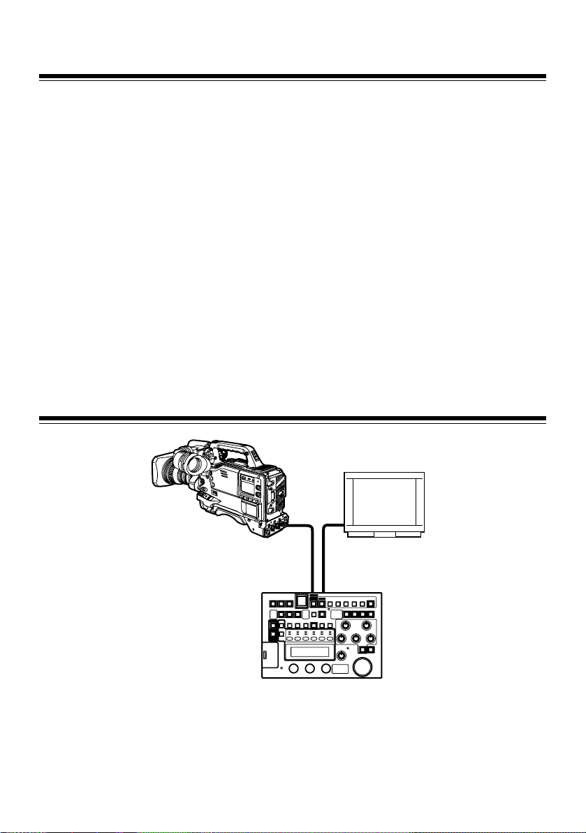
Connection
1
While the power supply of the camera
recorder is turned off, connect the RCU 10pin connector of the camera recorder to the
unit with the connection cable.
If settings are made from the camera menu,
set the frequency to the frame frequency of
the camera recorder and connect an NTSC
or PAL monitor.
2 After turning on the camera recorder power,
turn the unit power on.
System configuration
<Notes>
z The frame frequency of the camera recorder
must be switched before connecting the unit to
the camera recorder.
At VIDEO output, NTSC signals are output for
60 Hz operation, while PAL signals are output
for 50 Hz operation.
z The settings for FUNC on the menu determine
whether the camera recorder’s settings, which
are adjusted when the unit is connected, are
returned to the settings before connecting the
unit or to the state after adjustment, when the
unit is disconnected from the camera recorder.
z Do not forcefully pull the connected cable.
When the camera recorder is used while it is
being moved, the cable must be fixed to the
tripod or the handle of the camera recorder so
that no force is applied directly to the
connector.
Monitor
Camera recorder
Dedicated 10-pin cable Video cable
Camera connection connector VIDEO OUT connector
AJ-RC10G
<Note>
To determine whether the camera recorder supports the use of the unit, consult our sales dealers or the
operation manual of the camera recorder.
E-5
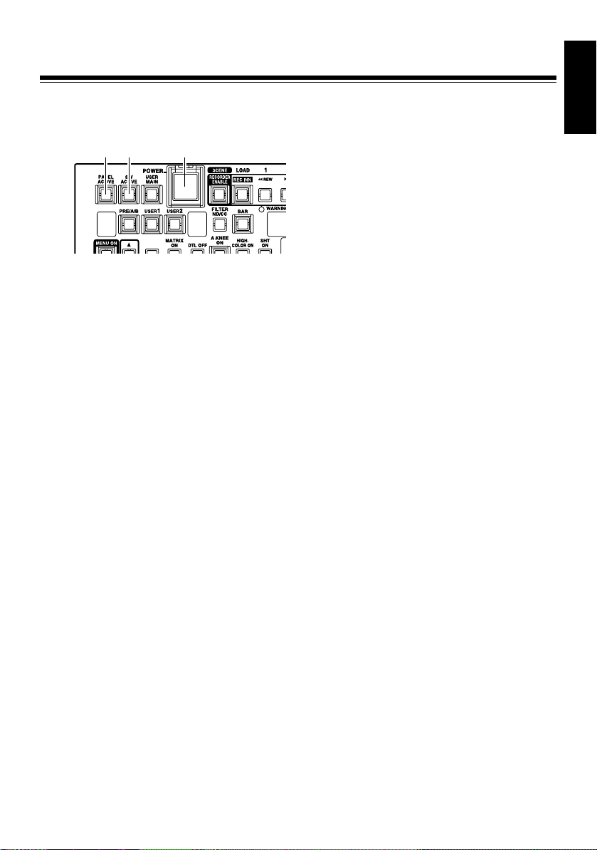
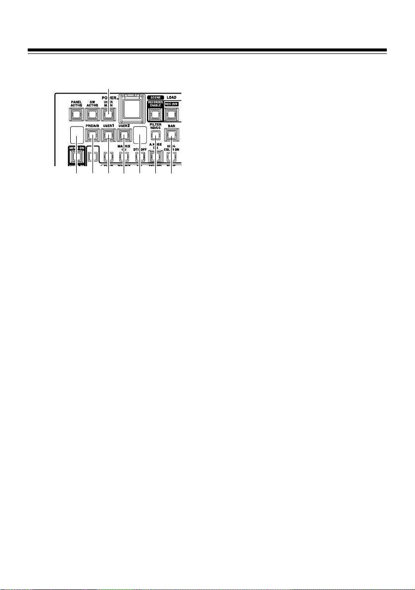
Parts and functions
Front panel
Panel part
!3"
!2"
!1" POWER button
ON/OFF switch of the main power supply of
the main unit
!2" PANEL ACTIVE button
For controlling which panel operations are
available
When the lamp is on:
The panel operations are available.
When the power is on, the unit is on.
When the lamp is off:
Only the POWER button and the PANEL
ACTIVE button are available; all other
button operations are disabled.
Turning on the self-lighting buttons and the
LED display, which indicate the operating
conditions of the camera recorder, follow the
operating conditions of the camera recorder.
!1"
!3" SW ACTIVE button
For enabling button/switch operations
When the lamp is on:
The button/switch operations are
enabled.
When the lamp is off:
Only the POWER button, PANEL
ACTIVE button, SW ACTIVE button, VR
ACTICVE button, AUTO IRIS button,
M.PED volume, and IRIS volume are
available; all other operations are
disabled.
Turning on the self-lighting SW and the LED
display, which indicate the operating
conditions of the camera recorder, follow the
operating conditions of the camera recorder.
ENGLISH
E-6

Parts and functions (Continued)
H
Camera recorder/Scene file operation
!1"
!2"
!3"
!4"
!5"
!6"
!7"
!8"
!9"
!1" RECORDER ENABLE button
For switching between the recorder mode
and the scene file mode
When the lamp is on:
Recorder mode
Buttons from !3" to !8" are operated as
control buttons for the recording.
When the lamp is off:
Scene file mode
Buttons from !3" to !8" are operated as the
buttons for reading and storing scene
files. When the power is turned on, the
unit is in this state.
!2" REC.INH/LOAD button
In recorder mode:
When the lamp is on, the REC S/S button !8"
is inhibited.
However, even if the unit is in the recording
inhibition state, operation of the USER
button assigned REC function and operation
of the REC button on the camera recorder
are enabled.
The lamp is off when the power is on.
In scene file mode:
The button is operated as the LOAD switch
of the scene file. Data are retrieved from the
file on the remote controller.
!3" REW/1 button
In recorder mode:
This button is operated in the same way as
the REW button on the camera recorder,
and the lamp is on when a tape is rewinding.
In the scene file mode:
1 is selected as the number for the scene
file to be saved or loaded.
!4" FF/2 button
In recorder mode:
This button is operated in the same way as
the FF button on the camera recorder, and
the lamp is on when a tape is fastforwarding.
In scene file mode:
2 is selected as the number for the scene
file to be saved or loaded.
!5" STOP/3-button
In recorder mode:
This button is operated in the same way as
the STOP button on the camera recorder,
and the lamp is on when a tape stops.
In scene file mode:
3 is selected as the number for the scene
file to be saved or loaded.
!6" PLAY/4-button
In recorder mode:
This button is operated in the same way as
the PLAY button on the camera recorder,
and the lamp is on when a tape is replayed.
If the button is pressed again during tape
replay, it changes to replay/pause, and the
lamp flashes.
If the button is pressed one more time, the
unit returns to replaying, and the lamp is on
continuously.
In scene file mode:
4 is selected as the number for the scene
file to be saved or loaded.
E-7

Parts and functions (Continued)
!7" CHECK/5-button
In recorder mode:
This is the recording confirmation button. If
the button is pressed when recording is
paused, the recording can be checked.
The lamp flashes when the tape is rewound
and is turned on when the tape is replayed.
In scene file mode:
5 is selected as the number for the scene
file to be saved or loaded.
!8" REC S/S / SAVE button
In recorder mode:
This is the start/stop button for recording.
This button is operated in the same way as
the REC START button on the camera
recorder, and the lamp is on during
recording.
In scene file mode:
This button is operated in the same way as
the SAVE button for scene data.
The current data are stored in the file on the
remote controller, which is selected by using
the buttons from !3" to !7".
!9" RECORDER WARNING lamp
This lamp flashes or is turned on when an
error occurs on the camera recorder, just
like the WARNING lamp on the camera
recorder. For details, refer to the operation
manual of the camera recorder.
ENGLISH
E-8
Parts and functions (Continued)
Basic camera operations
!1"
!5"
!4"
!2"
!3"
!7"
!6"
!1" USER MAIN button
This button has the same function as the
USER MAIN switch on the camera recorder.
The lamp is on only when the button is
pressed.
<Note>
Functions assigned to the USER MAIN
button are selected in the menu of the
camera recorder or the unit.
!2" USER1 button
This button has the same function as the
USER1 switch on the camera recorder. The
lamp is on only when the button is pressed.
<Note>
Functions assigned to the USER1 button
are selected in the menu of the camera
recorder or the unit.
!3" USER2 button
This button has the same function as the
USER2 switch on the camera recorder. The
lamp is on only when the button is pressed.
<Note>
Functions assigned to the USER2 button
are selected in the menu of the camera
recorder or the unit.
!8"
!4" PRE/A/B button
Operations of this button are the same as
for the WHITE BAL switch on the camera
H
recorder to select PRE, A or B.
The state will switch to “PRE” # “A” # “B”
# “PRE” step by step every time the button
is pressed.
When the power is turned on, the unit is in
the state it was before turning off the power.
!5" PRE/A/B display
This displays the WHITE BAL selection on
the camera recorder using P/A/b
!6" FILTER ND/CC button
This switches the FILTER display on the CC/
ND display !7" between ND filter and the CC
filter alternately.
!7" CC/ND Display
This displays the ND or CC selection using
the FILTER ND/CC !6" button.
For the ND filter display, the filter position is
indicated with 1/2/3/4.
For the CC filter display, the filter position is
indicated with A/b/C/d.
For the single filter, filter switching is
disabled. 1/2/3/4 is displayed depending on
the filter position.
When the power is on, the ND filter position
is displayed.
!8" BAR ON/OFF button
This button switches the output from the
camera recorder between the color bar and
the camera signals.
When the output from the camera recorder
is the color bar, the lamp is on; otherwise, it
is off.
When the power is turned on, the unit is in
the state it was before turning off the power.
E-9

Parts and functions (Continued)
Basic camera operations (Continued)
!10"
!9"
H
!11"
!12"
!13"
!9" GAIN display
This displays the image gain of the camera
recorder. The initial value is the gain value
at the time when the GAIN switch on the
camera recorder was set to “L”.
!10" M.GAIN 3 button
When this button is pressed, the image gain
of the camera recorder is increased.
The lamp is on only when this button is
pressed.
!11" M.GAIN 4 button
When this button is pressed, the image gain
of the camera recorder is reduced.
The lamp is on only when this button is
pressed.
!12" AWB button
When this button is pressed, the camera
recorder starts the AWB (Auto White
Balance) operation.
When this button is pressed during AWB
operation, the AWB operation will forcibly
terminate.
The lamp is on during AWB operation and
off when the operation is completed
correctly. If AWB operation finishes
incorrectly, the lamp will flash for 5 seconds
and then turn off.
!13" ABB button
When this button is pressed, the camera
recorder starts the ABB (Auto Black
Balance) operation.
When this button is pressed during the ABB
operation, the ABB operation will forcibly
terminate.
The lamp is on during ABB operation and off
when the operation is completed correctly. If
the ABB operation finishes incorrectly, the
lamp will flash for 5 seconds and then turn
off.
ENGLISH
E-10
Loading...