


 Loading...
ELECTRICAL ADJUSTMENT
Model No. : AJ-PX270/EJ, AJ-PX285MC,298MC
CONTENTS
1. Introduction of Electrical Adjustment ........................................................................................... |
ELE-1 |
1-1. Adjustment after replacement of major parts ....................................................................... |
ELE-1 |
1-2. Adjustment Item.................................................................................................................... |
ELE-2 |
1-3. PC EVR Software ................................................................................................................. |
ELE-3 |
1-3-1. Connection ................................................................................................................. |
ELE-3 |
1-3-2. Setup of EVR software............................................................................................... |
ELE-4 |
1-3-3. Button operation......................................................................................................... |
ELE-4 |
2. Camera Adjustment Procedure ................................................................................................... |
ELE-19 |
2-1. Preparation ........................................................................................................................... |
ELE-19 |
2-1-1. Initial settings ............................................................................................................. |
ELE-19 |
2-1-2. Save the backup data ................................................................................................ |
ELE-19 |
2-2. IRIS OIS GYRO Adjustment................................................................................................. |
ELE-20 |
2-3. ZOOM Lever Adjustment...................................................................................................... |
ELE-20 |
2-4. IRIS Diameter Adjustment. ................................................................................................... |
ELE-21 |
2-5-1. Sensitivity Adjustment. ...................................................................................................... |
ELE-22 |
2-5-2. Sensitivity Confirmation..................................................................................................... |
ELE-23 |
2-6. Zoom tracking / De-focus Adjustment. ................................................................................. |
ELE-24 |
2-7. White Balance Adjustment (3100K). .................................................................................... |
ELE-26 |
2-8. White Balance Adjustment (5600K). .................................................................................... |
ELE-27 |
2-9. White Shading Adjustment. .................................................................................................. |
ELE-28 |
2-10. Black Blemish Compensation............................................................................................. |
ELE-29 |
2-11. ND Filter Adjustment .......................................................................................................... |
ELE-30 |
2-12. VBS Level Adjust (59.94Hz) ............................................................................................... |
ELE-31 |
2-13. VBS Level Adjust (50Hz). ................................................................................................... |
ELE-32 |
2-14. INT Clock Frequency Adjustment....................................................................................... |
ELE-33 |
2-15. LCD Back Light Adjustment................................................................................................ |
ELE-34 |
2-16. LEVEL Gauge Adjustment.................................................................................................. |
ELE-34 |
2-17. MIC Balance Adjustment .................................................................................................... |
ELE-35 |
2-18. Time / Zoon Setting ............................................................................................................ |
ELE-35 |
2-19. White Blemish Confirmation ............................................................................................... |
ELE-36 |
2-20. Black Blemish Confirmation................................................................................................ |
ELE-36 |
2-21. White Shading Confirmation............................................................................................... |
ELE-36 |

1. Introduction of Electrical Adjustment
1-1. Adjustment after replacement of major parts
When the following parts is replaced showing in the table below, the adjustment and confirmation are required follow the items shown by mark “X” in the table.
|
PART NAME |
*MAIN P.C.B. |
|
HANDLE Unit |
|
GRIP |
LCD |
Battery |
||
|
LENS |
|
Unit |
Unit |
Unit |
|||||
|
|
|
|
|
|
|
||||
|
|
When |
When no |
Unit |
|
Handle |
INT |
Zoom |
Monitor |
Battery |
|
|
Backup |
backup |
|
|
SW |
PCB |
PCB |
||
NO |
ADJUSTMENT |
|
|
OP PCB |
MIC |
PCB |
||||
|
|
|
|
|
|
|||||
|
|
|
|
|
|
|
|
|
|
|
2-2 |
IRIS OIS GYRO |
X |
X |
X |
|
|
|
|
|
X |
2-3 |
ZOOM Lever |
|
X |
|
|
|
|
X |
|
|
2-4 |
IRIS Diameter |
X |
X |
X |
|
|
|
|
|
|
2-5 |
Sensitivity |
X |
X |
X |
|
|
|
|
|
|
2-6 |
Zoom tracking/De-focus |
X |
X |
X |
|
|
|
|
|
|
2-7 |
White Balance (3100K) |
|
X |
X |
|
|
|
|
|
|
2-8 |
White Balance (5600K) |
|
X |
X |
|
|
|
|
|
|
2-9 |
White Shading |
|
X |
X |
|
|
|
|
|
|
2-10 |
Black Blemish |
|
X |
X |
|
|
|
|
|
|
Compensation |
|
|
|
|
|
|
|
|||
|
|
|
|
|
|
|
|
|
|
|
2-11 |
ND Filter |
|
X |
X |
|
|
|
|
|
|
2-12 |
VBS LEVEL (59.94Hz) |
X |
X |
|
|
|
|
|
|
|
2-13 |
VBS LEVEL (50Hz) |
X |
X |
|
|
|
|
|
|
|
2-14 |
INT Clock Frequency |
X |
X |
|
|
|
|
|
|
|
2-15 |
LCD Back Light |
|
X |
|
|
|
|
|
X |
|
2-16 |
LEVEL Gauge |
X |
X |
|
X |
X |
|
|
|
|
2-17 |
MIC Balance |
X |
X |
|
X |
X |
X |
|
|
|
2-18 |
Time / Zone setting |
X |
X |
|
|
|
|
|
|
|
2-19 |
White Blemish |
X |
X |
X |
|
|
|
|
|
|
Confirmation |
|
|
|
|
|
|
||||
|
|
|
|
|
|
|
|
|
|
|
|
|
|
|
|
|
|
|
|
|
|
|
|
|
|
|
|
|
|
|
|
|
X: Adjustment / Confirmation Required
The method of data backup (CAM EEPROM) has been described to the item “7. Data Backup Procedure” of service information (SECTION 1).
The method of white blemish compensation has been described to the item “8. White Blemish Compensation” of service information (SECTION 1).
ELE-1

1-2. Adjustment Item
Below indicated tools are required to perform each adjustment in addition to tools in introduced in item 1-1-1.
ADJUSTMENT ITEM |
Required Tool and equipment |
Remark |
Save |
|
IRIS OIS GYRO Adjustment |
Unnecessary |
AUTO |
LENS |
|
Adj. |
EEPROM |
|||
|
|
|||
ZOOM Lever Adjustment |
Unnecessary |
Manual |
LENS |
|
Adj. |
EEPROM |
|||
|
|
|||
|
Gray Scale Chart |
Manual |
LENS |
|
IRIS Diameter Adjustment |
Halogen lamp |
Adj. |
EEPROM |
|
Color Pyrometer & Lux Meter |
|
|
||
|
|
|
||
|
HD SDI WFM |
|
|
|
|
Halogen lamp |
AUTO |
LENS |
|
|
Adj. |
EEPROM |
||
Zoom tracking and De-focus Adjustment |
Collimator (RFKZ0422) |
|||
|
CAM |
|||
|
Collimator Adaptor |
|
||
|
|
EEPROM |
||
|
|
|
||
|
Gray Scale Chart |
Manual |
CAM |
|
Sensitivity Adjustment |
Halogen lamp |
Adj. |
EEPROM |
|
Color Pyrometer & Lux Meter |
|
|
||
|
|
|
||
|
HD SDI WFM |
|
|
|
|
Gray Scale Chart |
AUTO |
CAM |
|
White Balance Adjustment (3100K) |
Halogen lamp |
Adj. |
EEPROM |
|
Color Pyrometer & Lux Meter |
|
|
||
|
WFM |
|
|
|
|
Vector scope |
|
|
|
|
CC filter (VFK1347,VFK1884,VFK1888) |
AUTO |
CAM |
|
|
Filter holder (VFK1345) |
Adj. |
EEPROM |
|
|
Step down ring (VFK1346) |
|
|
|
White Balance Adjustment (5600K) |
Gray Scale Chart |
|
|
|
Halogen lamp |
|
|
||
|
|
|
||
|
Color Pyrometer & Lux Meter |
|
|
|
|
WFM |
|
|
|
|
Vector scope |
|
|
|
|
White Chart |
AUTO |
CAM |
|
White Shading Adjustment |
Halogen lamp |
Adj. |
EEPROM |
|
|
Color Pyrometer & Lux Meter |
|
|
|
|
White Chart |
AUTO |
CAM |
|
Black Blemish Compensation |
Halogen lamp |
Adj. |
EEPROM |
|
|
Color Pyrometer & Lux Meter |
|
|
|
|
Gray Scale Chart |
AUTO |
CAM |
|
ND FILTER Compensation Adjustment |
Halogen lamp |
Adj. |
EEPROM |
|
|
Color Pyrometer & Lux Meter |
|
|
|
Video Output Level Adjustment |
SD WFM or Oscilloscope |
Manual |
BE |
|
Adj. |
|
|||
|
|
|
||
Int. Clock Frequency Adjustment |
SD NTSC/PAL Composite Signal Generator |
Manual |
BE |
|
SD WFM or Oscilloscope |
Adj. |
|
||
|
|
|||
Level Gauge Adjustment |
Level Gauge |
AUTO |
BE |
|
Adj. |
|
|||
|
|
|
||
MIC Balance Adjustment |
Unnecessary |
AUTO |
BE |
|
Adj. |
|
|||
|
|
|
||
LCD Back Light Adjustment |
Unnecessary |
Manual |
BE |
|
Adj. |
|
|||
|
|
|
||
Time / Zone setting |
Unnecessary |
AUTO |
BE |
|
Adj. |
|
|||
|
|
|
||
|
|
|
|
ELE-2
1-3. PC EVR software
All adjustments are performed by PC EVR software “VVS0114”.
When the PC EVR software is used, the following tools are required.
NAME |
Part Number |
Pcs. |
Remark |
PC EVR software |
VVS0114 |
1 |
Download from the Global Service WEB site. |
USB Driver for AG-HPX250/260 EVR Adjustment |
VSI5386B |
1 |
Download from the Global Service WEB site. |
USB cable A type ↔ mini B type |
--- |
1 |
|
Personal Computer |
--- |
1 |
*NOTE: |
*OS: Windows XP SP2 / SP3, Windows7 32bit
In order to communicate with PC EVR software “VVS0114”, it is necessary to install USB driver software “VSI5386B” in PC. Please refer to “6-2. Setup” of section1.
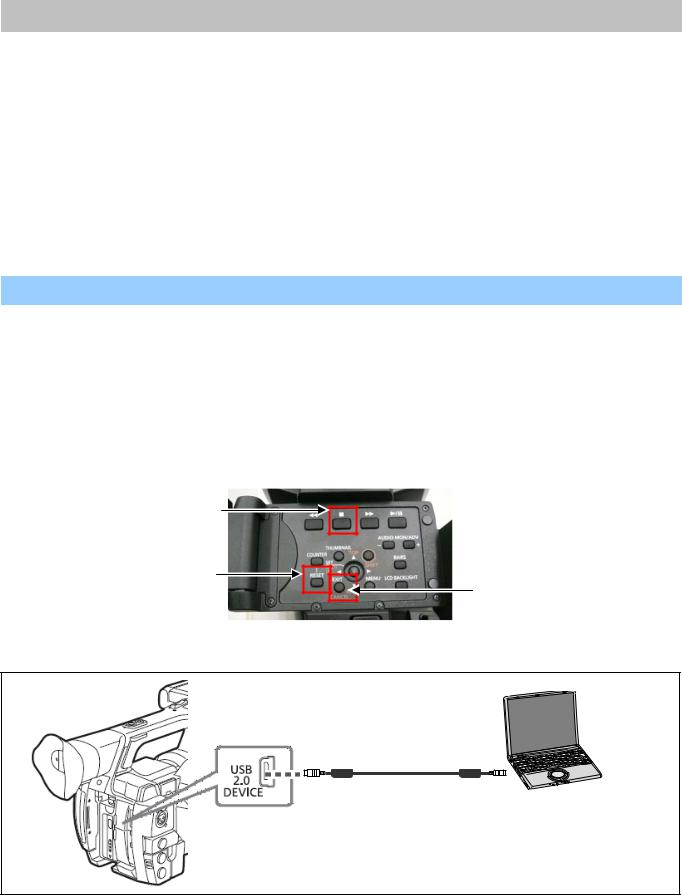
1-3-1. Connection
1. Set this camera recorder to COM mode.
< Setting method of COM mode >
1-1. Turn the power on.
1-2. The COM mode is set by hold down the “STOP” button, “EXIT” button and “RESET” button at the same time for three seconds or more. (The character of “COM*” is displayed on the LCD screen when the COM mode is set.).
NOTE: To cancel the COM mode, execute the operation of the same button as the setting. If the “ * “ mark has disappeared, COM mode is cancelled. When the power is turned ON next time, COM character disappears.
STOP
RESET
EXIT
2. Connect the USB cable between USB connector and PC.
USB cable
mini B type |
A type |
ELE-3
1-3-2. Setup of EVR software
1.Download the file “PC EVR Software (VVS0114)” from Global Service Web Site.
2.Make any directory and then copy all files in VVS0114.
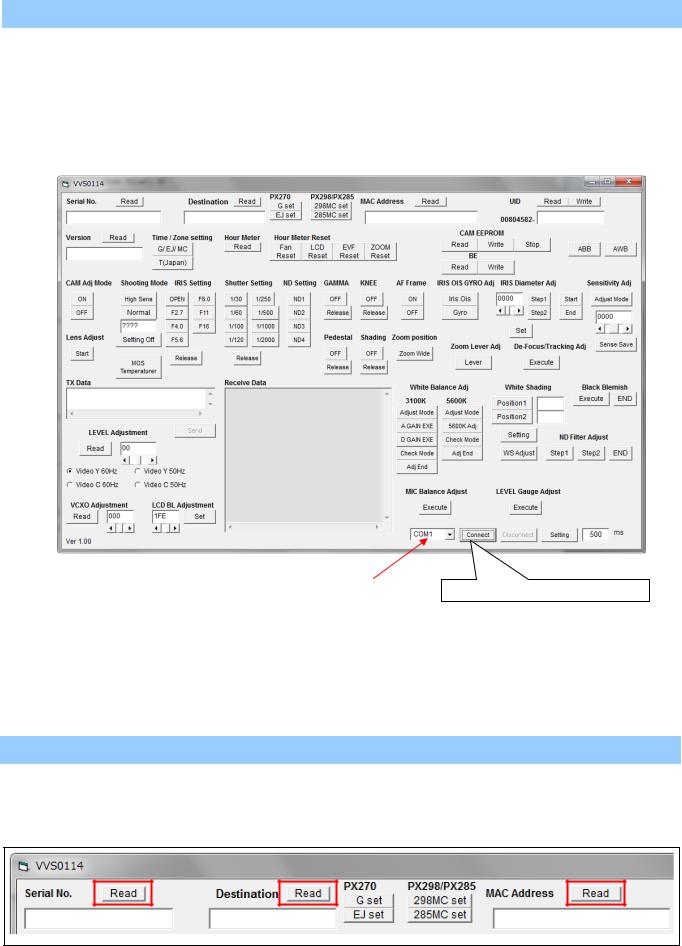
3.Double click the “vvs0114.exe” in the “vvs0114” folder to boot-up the software. The following screen is displayed.
4.After selecting COM port, click the “Connect” button to start communication between Camera and VVS0114.
|
|
|
|
|
|
|
|
|
|
|
|
|
|
|
|
|
|
|
Select COM port number of your PC. |
|
Communication starting button |
||
|
|
|
|
|
|
|
|
|
|
|
|
1-3-3. Button operation
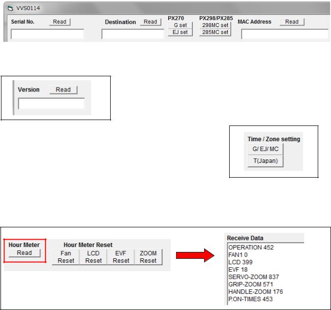
< 1. Serial No. / Destination / MAC Address Read >
Clicking “Read” button for Serial No., Serial No. is displayed. Clicking “Read” button for Model Name, Model Name is displayed. Clicking “Read” button for MAC Address, MAC Address is displayed.
ELE-4
< 2. Destination setting >
After replacing the Main P.C.B, execute the Destination setting.
AJ-PX270(Japan), P, EN, AN, PX |
: Click “G set” button. |
||
AJ-PX270EJ |
: Click “EJ set” button. |
||
AJ-PX298MC |
: Click “298MC set” button. |
||
AJ-PX285MC |
: Click “285MC set” button. |
||
|
|
|
|
|
|
|
|
|
|
|
|
< 3. Version read >
Clicking “Read” button for Version, the total number of the firmware version is displayed.
< 4. Time / Zone setting >
The time and time zone of the internal clock is set.
AJ-PX270P,EJ,EN,AN,PX/PX298MC/285MC |
: Click “G / EJ / MC” button. |
AJ-PX270(Japan) |
: Click “T(Japan)” button. |
< 5. Hour Meter information >
Clicking “Read” button for Hour Meter, the hour meter information is displayed in Receive Data window.
NOTE: FAN hour meter is the effective information after Ver2 firmware.
OPERATION |
: Total operation hour |
FAN1 |
: FAN operation hour |
LCD |
: LCD operation hour |
EVF |
: EVF operation hour |
SERVO-ZOOM |
: ZOOM motor moving times |
GRIP-ZOOM |
: GRIP ZOOM button operation times |
HANDL-ZOOM |
: HANDLE ZOOM button operation times |
P.ON-TIMES |
: The number of times of turning on power |
< 6. Hour Meter Reset >
Clicking “Fan Reset” button, the hour meter of FAN is set zero hour. When replacing FAN, click “Fan Reset” button for FAN Hour Meter. NOTE: FAN hour meter reset is the effective function after Ver2 software.
ELE-5

Clicking “LCD Reset” button, the hour meter of LCD is set zero hour.
When replacing LCD, click “LCD Reset” button for LCD Hour Meter.
Clicking “EVF Reset” button, the hour meter of EVF is set zero hour.
When replacing EVF, click “EVF Reset” button for EVF Hour Meter.
Clicking “ZOOM Reset” button, the hour meter of SERVO-ZOOM motor is set zero hour. When replacing ZOOM motor , click “ZOOM Reset” button for SERVO-ZOOM Hour Meter.
< 7. UID reading and writing >
Clicking “Read” button for UID, UID number is displayed.
When writing UID, input a number (8 figures) in the window and then click “Write” button. If the number which should be written is not known, click “Write” button with a blank.
A number is generated and written in automatically.
When “&set UID OK” is displayed in Receive Data window, the writing is completed.
|
|
|
|
|
|
|
Input a number. |
Read |
|
|
Write |
|
|
If unknown, with a blank. |
|
|
|
|
|
|
|
|
|
|
|
|
|
|
|
|
|
|
|
|
|
|
|
|
|
< 8. CAM EEPROM READ >
Click “Read” button of CAM EEPROM. When Dump Data is displayed in RX Data window, Data Backup is completed. It takes approx. 15 seconds.
Backup Data is saved as “PX270_yy_mm_dd_hh_nn.txt” file in “SaveRom” folder of vvs0114. yy: year, mm: month, dd: day, hh: hour, nn: minute
ELE-6
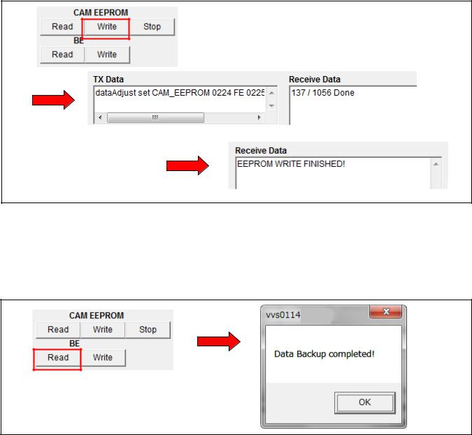
< 9. CAM EEPROM WRITE >
1.Click “Write” button of CAM EEPROM. File selection dialog opens.
2.Select a backup file which you want to write from SaveRom folder.
3.Clicking “Open” button, the writing starts. When “EEPROM WRITE FINISHED!” is displayed in Receive Data window, the writing is completed. It takes approx. 9 minutes by the completion.
< 10. BE DATA READ >
Click “Read” button of BE. When “Data Backup completed!” message is displayed, Data Backup is completed. It takes approx. 15 seconds.
NOTE: Backup Data is saved as “PX270_backup_yy_mm_dd_hh_nn.TXT” file in “SysBackup” folder of vvs0114.
yy: year, mm: month, dd: day, hh: hour, nn: minute
ELE-7
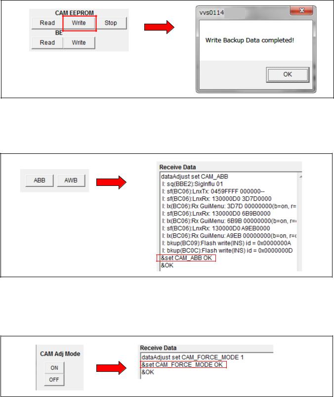
< 11. BE DATA WRITE >
1.Click “Write” button of BE. File selection dialog opens.
2.Select a backup file which you want to write from SysBackup folder.
3.Clicking “Open” button, the writing starts. When “WRITE Backup Data Completed!” message is displayed, the writing is completed. It takes approx. 10 seconds by the completion.
< 10. AWB / ABB >
Clicking “AWB” button, AWB is executed. Clicking “ABB” button, ABB is executed.
When “&set CAM_ABB OK” or “&set CAM_AWB OK” is displayed in Receive Data window, ABB (AWB) is completed.
< 11. CAM Adj. Mode setting >
It is a button which makes Camera adjustment mode. In case of setting to adjustment mode, click “ON” button.
In case of releasing from adjustment mode, click “OFF” button.
When “&set CAM_FORCE_MODE OK” is displayed in Receive Data window, the setting is completed.
ELE-8
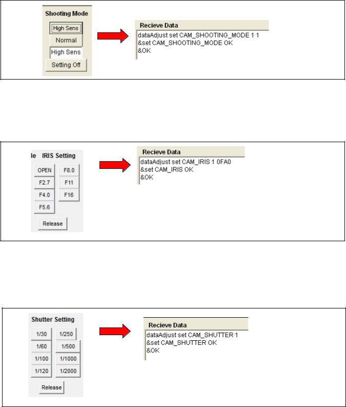
< 12. Shooting Mode setting >
Shooting mode can be changed with this button.
High Sens : Camera setting is set to High sensitivity mode. Normal : Camera setting is set to Normal sensitivity mode. Setting Off : The compulsive setting from PC is released.
When “&set CAM_SHOOTING_MODE OK” is displayed in Receive Data window, the setting is completed.
< 13. IRIS setting >
It is possible to set IRIS to the iris value indicated on each button. Release : The compulsive setting from PC is released.
When “&set CAM_IRIS OK” is displayed in Receive Data window, the setting is completed.
< 14. Shutter setting >
It is possible to set Shutter to the shutter value indicated on each button. Release : The compulsive setting from PC is released.
When “&set CAM_SHUTTER OK” is displayed in Receive Data window, the setting is completed.
ELE-9
< 15. ND filter setting >
It is possible to set ND filter to the ND filter position indicated on each button.
When “&set CAM_FORCE_ND OK” is displayed in Receive Data window, the setting is completed.
< 16. GAMMA OFF setting >
It is possible to set GAMMA to OFF. OFF : GAMMA is set to OFF.
Release : The compulsive setting from PC is released.
When “&set CAM_GAMMA_OFF OK” is displayed in Receive Data window, the setting is completed.
< 17. KNEE OFF setting >
It is possible to set KNEE to OFF. OFF : KNEE is set to OFF.
Release : The compulsive setting from PC is released.
When “&set CAM_KNEE_OFF OK” is displayed in Receive Data window, the setting is completed.
< 18. PEDESTAL OFF setting >
It is possible to set PEDESTAL to OFF. OFF : PEDESTAL is set to OFF.
Release : The compulsive setting from PC is released.
When “&set CAM_PEDESTAL_OFF OK” is displayed in Receive Data window, the setting is completed.
ELE-10
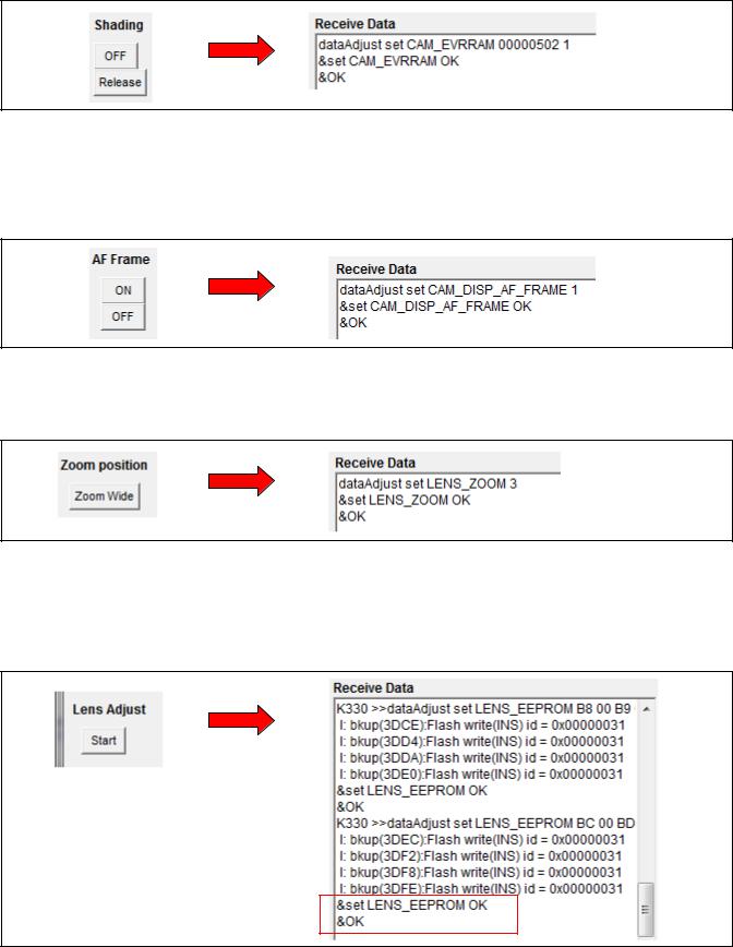
< 19. White Shading OFF setting >
It is possible to set White Shading to OFF. OFF : White Shading is set to OFF.
Release : The compulsive setting from PC is released.
When “&set CAM_EVRRAM OK” is displayed in Receive Data window, the setting is completed.
< 20. AF Frame ON/OFF setting >
When adjusting Zoom Tracking, It is a button for displaying the focus window on the LCD panel. ON : Focus window display ON
OFF : Focus window display OFF
When “&set CAM_DISP_AF_FRAME OK” is displayed in Receive Data window, the setting is completed.
< 21. Zoom position Wide setting >
It is possible to set Zoom position to Wide terminal.
When “&set LENS_ZOOM OK” is displayed in Receive Data window, the setting is completed.
< 22. Lens Adjustment Start >
In case of replacing Lens Unit or Main P.C.B, be sure to click this “Start” button before starting Lens Adjustment. By clicking this button, the initial setting data is set to EEPROM.
When “&set LENS_EEPROM OK” is displayed at the last line in Receive Data window, the initial setting is completed.
ELE-11
Loading...