


 Loading...
Manual No.
TOEPC71060605-02-OY
VARISPEED V7
Compact Sensorless Vector Inverter
USER’S MANUAL

PREFACE
Omron Yaskawa Motion Control (from now OYMC) V7AZ is a small and simple Inverter, as easy to use as a contactor. This instruction manual describes installation, maintenance, inspection, troubleshooting, and specifications of the V7AZ. Read this instruction manual thoroughly before operation.
OMRON YASKAWA MOTION CONTROL
General Precautions
•Some drawings in this manual are shown with protective covers or shields removed in order to show detail with more clarity. Make sure all covers and shields are replaced before operating the product.
•This manual may be modified when necessary because of improvements to the product, modifications, or changes in specifications.
Such modifications are indicated by revising the manual number.
•To order a copy of this manual, or if your copy has been damaged or lost, contact your OMRON representative.
•OMRON YASKAWA is not responsible for any modification of the product made by the user, since that will void the guarantee.
1
NOTATION FOR SAFETY PRECAUTIONS
Read this instruction manual thoroughly before installation, operation, maintenance, or inspection of the V7AZ. In this manual, safety precautions are classified as either warnings or cautions and are indicated as shown below.

 WARNING
Indicates a potentially hazardous situation which, if not avoided, may result in death or serious injury.

 CAUTION
Indicates a potentially hazardous situation which, if not avoided, may result in minor or moderate injury or damage to equipment.
It may also be used to alert against unsafe practices.
Even items classified as cautions may result in serious accidents in some situations. Always follow these important precautions.
NOTE : Indicates information to insure proper operation.
2

PRECAUTIONS FOR UL/cUL MARKING
•Do not connect or disconnect wiring, or perform signal checks while the power supply is turned ON.
•The Inverter internal capacitor is still charged even after the power supply is turned OFF. To prevent electric shock, disconnect all power before servicing the Inverter, and then wait at least one minute after the power supply is disconnected. Confirm that all indicators are OFF before proceeding.
•Do not perform a withstand voltage test on any part of the Inverter. The Inverter is an electronic device that uses semiconductors, and is thus vulnerable to high voltage.
•Do not remove the Digital Operator or the blank cover unless the power supply is turned OFF. Never touch the printed circuit board (PCB) while the power supply is turned ON.
•This Inverter is not suitable for use on a circuit capable of delivering more than 18,000 RMS symmetrical amperes, 250 V maximum (200 V Class Inverters) or 18,000 RMS symmetrical amperes, 480 V maximum (400 V Class Inverters).
 CAUTION
• Use 75°C copper wire or the equivalent.
PRECAUTIONS FOR CE MARKINGS
•Only basic insulation to meet the requirements of protection class 1 and overvoltage category II is provided with control circuit terminals. Additional insulation may be necessary in the end product to conform to CE requirements.
•For 400 V Class Inverters, make sure to ground the supply neutral to conform to CE requirements.
•For conformance to EMC directives, refer to the relevant manuals for the requirements.
Document No. EZZ006543
3

RECEIVING THE PRODUCT
 CAUTION
(Ref. page)
• Do not install or operate any Inverter that is 18 damaged or has missing parts.
Failure to observe this caution may result in injury or equipment damage.
MOUNTING
 CAUTION
|
|
(Ref. page) |
• |
Lift the Inverter by the heatsinks. When moving |
23 |
|
the Inverter, never lift it by the plastic case or the |
|
|
terminal cover. |
|
|
Otherwise, the main unit may fall and be damaged. |
|
• |
Mount the Inverter on nonflammable material |
23 |
|
(i.e., metal). |
|
|
Failure to observe this caution may result in a fire. |
|
• When mounting Inverters in an enclosure, install |
23 |
|
|
a fan or other cooling device to keep the intake |
|
|
air temperature below 50 °C (122 °F) for IP20 |
|
|
(open chassis type), or below 40 °C (105 °F) for |
|
|
NEMA 1 (TYPE 1). |
|
|
Overheating may cause a fire or damage the Inverter. |
|
• The V7AZ generates heat. For effective cooling, |
24 |
|
|
mount it vertically. |
|
|
Refer to the figure in Choosing a Location to |
|
|
Mount the Inverter on page 24. |
|
4

WIRING
 WARNING
|
|
|
(Ref. page) |
• |
Only begin wiring after verifying that the power |
28 |
|
|
supply is turned OFF. |
|
|
|
Failure to observe this warning may result in an elec- |
|
|
|
tric shock or a fire. |
|
|
• |
Wiring should be performed only by qualified |
28 |
|
|
personnel. |
|
|
|
Failure to observe this warning may result in an elec- |
|
|
|
tric shock or a fire. |
|
|
• |
When wiring the emergency stop circuit, check |
28 |
|
|
the wiring thoroughly before operation. |
|
|
|
Failure to observe this warning may result in injury. |
|
|
• |
Always ground the ground terminal |
accord- |
34 |
|
ing to the local grounding code. |
|
|
|
Failure to observe this warning may result in an elec- |
|
|
|
tric shock or a fire. |
|
|
• |
For 400 V Class, make sure to ground the sup- |
37 |
|
|
ply neutral. |
|
|
|
Failure to observe this warning may result in an elec- |
|
|
|
tric shock or a fire. |
|
|
• If the power supply is turned ON while the FWD |
37 |
||
|
(or REV) Run Command is being given, the |
|
|
|
motor will start automatically. |
|
|
|
Turn the power supply ON after verifying that |
|
|
|
the RUN signal is OFF. |
|
|
|
Failure to observe this warning may result in injury. |
|
|
• |
When the 3-wire sequence is set, do not make |
112 |
|
|
the wiring for the control circuit unless the multi- |
|
|
|
function input terminal parameter is set. |
|
|
|
Failure to observe this warning may result in injury. |
|
|
5

 CAUTION
|
|
(Ref. page) |
• |
Verify that the Inverter rated voltage coincides |
28 |
|
with the AC power supply voltage. |
|
|
Failure to observe this caution may result in personal |
|
|
injury or a fire. |
|
• |
Do not perform a withstand voltage test on the |
28 |
|
Inverter. |
|
|
Performing withstand voltage tests may damage |
|
|
semiconductor elements. |
|
• To connect a Braking Resistor, Braking Resistor |
34 |
|
|
Unit, or Braking Unit, follow the procedure |
|
|
described in this manual. |
|
|
Improper connection may cause a fire. |
|
• |
Always tighten terminal screws of the main cir- |
28 |
|
cuit and the control circuits. |
|
|
Failure to observe this caution may result in a mal- |
|
|
function, damage, or a fire. |
|
• Never connect the AC main circuit power supply |
28 |
|
|
to output terminals U/T1, V/T2, W/T3, B1, B2, -, |
|
|
+1, or +2. |
|
|
The Inverter will be damaged and the guarantee will |
|
|
be voided. |
|
• |
Do not connect or disconnect wires or connec- |
28 |
|
tors while power is applied to the circuits. |
|
|
Failure to observe this caution may result in injury. |
|
• |
Do not perform signal checks during operation. |
28 |
|
The machine or the Inverter may be damaged. |
|
• |
To store a constant with an Enter Command by |
155 |
|
communications, be sure to take measures for |
|
|
an emergency stop by using the external termi- |
|
|
nals. |
|
Delayed response may cause injury or damage the machine.
6

OPERATION
 WARNING
|
|
(Ref. page) |
• |
Only turn ON the input power supply after con- |
38 |
|
firming that the Digital Operator or blank cover |
|
|
(optional) are in place. Do not remove the |
|
|
Digital Operator or the covers while current is |
|
|
flowing. |
|
|
Failure to observe this warning may result in an elec- |
|
|
tric shock. |
|
• |
Never operate the Digital Operator or DIP |
38 |
|
switches with wet hands. |
|
|
Failure to observe this warning may result in an elec- |
|
|
tric shock. |
|
• |
Never touch the terminals while current is flow- |
38 |
|
ing, even if the Inverter is stopped. |
|
|
Failure to observe this warning may result in an elec- |
|
|
tric shock. |
|
• |
When the fault retry function is selected, stand |
84 |
|
clear of the Inverter or the load. The Inverter |
|
|
may restart suddenly after stopping. |
|
|
(Construct the system to ensure safety, even if the |
|
|
Inverter should restart.) Failure to observe this warn- |
|
|
ing may result in injury. |
|
• |
When continuous operation after power recov- |
79 |
|
ery is selected, stand clear of the Inverter or the |
|
|
load. The Inverter may restart suddenly after |
|
|
stopping. |
|
|
(Construct the system to ensure safety, even if the |
|
|
Inverter should restart.) Failure to observe this warn- |
|
|
ing may result in injury. |
|
• |
The Digital Operator stop button can be dis- |
98 |
|
abled by a setting in the Inverter. Install a sepa- |
|
|
rate emergency stop switch. |
|
|
Failure to observe this warning may result in injury. |
|
7

 WARNING
|
(Ref. page) |
• If an alarm is reset with the operation signal ON, |
37 |
the Inverter will restart automatically. Reset an |
|
alarm only after verifying that the operation sig- |
|
nal is OFF. |
|
Failure to observe this warning may result in injury. |
|
• When the 3-wire sequence is set, do not make |
112 |
the wiring for the control circuit unless the multi- |
|
function input terminal parameter is set. |
|
Failure to observe this warning may result in injury. |
|
• If n001=5, a Run Command can be received |
46, 53 |
even while changing a constant. If sending a |
|
Run Command while changing a constant, such |
|
as during a test run, be sure to observe all |
|
safety precautions. |
|
Failure to observe this warning may result in injury. |
|
 CAUTION
|
|
(Ref. page) |
• |
Never touch the heatsinks, which can be |
38 |
|
extremely hot. |
|
|
Failure to observe this caution may result in harmful |
|
|
burns to the body. |
|
• It is easy to change operation speed from low to |
38 |
|
|
high. Verify the safe working range of the motor |
|
|
and machine before operation. |
|
|
Failure to observe this caution may result in injury |
|
|
and machine damage. |
|
• |
Install a holding brake separately if necessary. |
38 |
|
Failure to observe this caution may result in injury. |
|
8

 CAUTION
(Ref. page)
• If using an Inverter with an elevator, take safety 187 measures on the elevator to prevent the eleva-
tor from dropping.
Failure to observe this caution may result in injury.
• Do not perform signal checks during operation. |
38 |
The machine or the Inverter may be damaged.
• All the constants set in the Inverter have been |
38 |
preset at the factory. Do not change the settings unnecessarily.
The Inverter may be damaged.
9
MAINTENANCE AND INSPECTION
 WARNING
|
|
(Ref. page) |
• |
Never touch high-voltage terminals on the |
192 |
|
Inverter. |
|
|
Failure to observe this warning may result in an elec- |
|
|
trical shock. |
|
• |
Disconnect all power before performing mainte- |
192 |
|
nance or inspection, and then wait at least one |
|
|
minute after the power supply is disconnected. |
|
|
For 400 V Class Inverters, confirm that all indi- |
|
|
cators are OFF before proceeding. |
|
|
If the indicators are not OFF, the capacitors are still |
|
|
charged and can be dangerous. |
|
• |
Do not perform a withstand voltage test on any |
192 |
|
part of the V7AZ. |
|
|
The Inverter is an electronic device that uses semi- |
|
|
conductors, and is thus vulnerable to high voltage. |
|
• |
Only authorized personnel should be permitted |
192 |
|
to perform maintenance, inspection, or parts |
|
|
replacement. |
|
|
(Remove all metal objects (watches, bracelets, etc.) |
|
before starting work.)
(Use tools which are insulated against electrical shock.)
Failure to observe these warnings may result in an electric shock.
10

 CAUTION
|
(Ref. page) |
• The control PCB employs CMOS ICs. |
192 |
Do not touch the CMOS elements. |
|
They are easily damaged by static electricity.
• Do not connect or disconnect wires, connectors, |
192 |
or the cooling fan while power is applied to the circuit.
Failure to observe this caution may result in injury.
OTHERS
 WARNING
•Never modify the product.
Failure to observe this warning may result in an electrical shock or injury and will void the guarantee.
 CAUTION
•Do not subject the Inverter to halogen gases, such as fluorine, chlorine, bromine, and iodine, at any time even during transportation or installation.
Otherwise, the Inverter can be damaged or interior parts burnt.
11
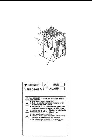
WARNING LABEL
A warning label is provided on the front cover of the Inverter, as shown below. Follow the warnings when handling the Inverter.
Plastic Case |
|
Status Indicators
Nameplate
Warning Label Location
Certification Mark
Warning Labels
FPST31042-874
Example of 5.5 kW for 400 V
12

CONTENTS
NOTATION FOR SAFETY PRECAUTIONS - - - - - - 2 1 Receiving the Product - - - - - - - - - - - - - - - - - - - 18
Checking the Nameplate - - - - - - - - - - - - - - - - - - - - - - - - - - |
19 |
2 Identifying the Parts - - - - - - - - - - - - - - - - - - - - - 20
3 Mounting - - - - - - - - - - - - - - - - - - - - - - - - - - - - 23
Choosing a Location to Mount the Inverter - - - - - - - - - - - - - - |
23 |
Mounting Dimensions - - - - - - - - - - - - - - - - - - - - - - - - - - - - - |
24 |
Mounting/Removing Components- - - - - - - - - - - - - - - - - - - - - |
25 |
Removing the Front Cover- - - - - - - - - - - - - - - - - - - - - - |
25 |
Mounting the Front Cover - - - - - - - - - - - - - - - - - - - - - - |
25 |
Removing the Terminal Cover - - - - - - - - - - - - - - - - - - - |
25 |
Mounting the Terminal Cover - - - - - - - - - - - - - - - - - - - - |
26 |
Removing the Digital Operator - - - - - - - - - - - - - - - - - - - |
26 |
Mounting the Digital Operator - - - - - - - - - - - - - - - - - - - |
26 |
Mounting the Bottom Cover - - - - - - - - - - - - - - - - - - - - - |
27 |
4 Wiring - - - - - - - - - - - - - - - - - - - - - - - - - - - - - - 28
Wire and Terminal Screw Sizes - - - - - - - - - - - - - - - - - - - - - - |
30 |
Wiring the Main Circuits- - - - - - - - - - - - - - - - - - - - - - - - - - - - |
34 |
Wiring the Control Circuits - - - - - - - - - - - - - - - - - - - - - - - - - - |
36 |
Wiring Inspection - - - - - - - - - - - - - - - - - - - - - - - - - - - - - - - - |
37 |
5 Operating the Inverter - - - - - - - - - - - - - - - - - - - 38
Test Run - - - - - - - - - - - - - - - - - - - - - - - - - - - - - - - - - - - - - - 39
Selecting Rotation Direction- - - - - - - - - - - - - - - - - - - - - 41
Operation Check Points- - - - - - - - - - - - - - - - - - - - - - - - 41
Operating the Digital Operator - - - - - - - - - - - - - - - - - - - - - - - 42
Description of Status Indicators - - - - - - - - - - - - - - - - - - 43
Function Indicator Description - - - - - - - - - - - - - - - - - - - - - - - 45
MNTR Multi-function Monitoring - - - - - - - - - - - - - - - - - - 46
Input/Output Terminal Status - - - - - - - - - - - - - - - - - - - - 48
Data Reception Error Display- - - - - - - - - - - - - - - - - - - - 48
13

Simple Data Setting - - - - - - - - - - - - - - - - - - - - - - - - - - - - - - -50
6 Programming Features - - - - - - - - - - - - - - - - - - 52
Hardware - - - - - - - - - - - - - - - - - - - - - - - - - - - - - - - - - - 52Software (Constant) - - - - - - - - - - - - - - - - - - - - - - - - - - -52Constant Setup and Initialization - - - - - - - - - - - - - - - - - - - - - - 53Constant Selection/Initialization (n001) - - - - - - - - - - - - - 53
Using V/f Control Mode - - - - - - - - - - - - - - - - - - - - - - - - - - - -55Adjusting Torque According to Application - - - - - - - - - - -55Using Vector Control Mode - - - - - - - - - - - - - - - - - - - - - - - - - - 59Precautions for Voltage Vector Control Application - - - - -59Motor Constant Calculation- - - - - - - - - - - - - - - - - - - - - - 60V/f Pattern during Vector Control- - - - - - - - - - - - - - - - - - 61
Switching LOCAL/REMOTE Mode - - - - - - - - - - - - - - - - - - - - 62How to Select LOCAL/REMOTE Mode - - - - - - - - - - - - - 63Selecting Run/Stop Commands- - - - - - - - - - - - - - - - - - - - - - - 63LOCAL Mode - - - - - - - - - - - - - - - - - - - - - - - - - - - - - - -63REMOTE Mode - - - - - - - - - - - - - - - - - - - - - - - - - - - - - -64Operating (Run/Stop Commands) by Communications - - 64
Selecting Frequency Reference - - - - - - - - - - - - - - - - - - - - - - 64LOCAL Mode - - - - - - - - - - - - - - - - - - - - - - - - - - - - - - -65REMOTE Mode - - - - - - - - - - - - - - - - - - - - - - - - - - - - - -65
Setting Operation Conditions - - - - - - - - - - - - - - - - - - - - - - - - 66Autotuning Selection (n139) - - - - - - - - - - - - - - - - - - - - -66Reverse Run Prohibit (n006)- - - - - - - - - - - - - - - - - - - - - 74Multi-step Speed Selection - - - - - - - - - - - - - - - - - - - - - - 74Operating at Low Speed - - - - - - - - - - - - - - - - - - - - - - - -75Adjusting Speed Setting Signal - - - - - - - - - - - - - - - - - - - 76Adjusting Frequency Upper and Lower Limits- - - - - - - - - 77Using Four Acceleration/Deceleration Times - - - - - - - - - 77Momentary Power Loss Ridethrough Method (n081)- - - -79S-curve Selection (n023) - - - - - - - - - - - - - - - - - - - - - - - 80Torque Detection - - - - - - - - - - - - - - - - - - - - - - - - - - - - - 81Frequency Detection Level (n095)- - - - - - - - - - - - - - - - -82Jump Frequencies (n083 to n086) - - - - - - - - - - - - - - - - -84Continuing Operation Using Automatic Retry Attempts - - 84Frequency Offset Selection (n146) - - - - - - - - - - - - - - - - 85
14

Operating a Coasting Motor without Tripping - - - - - - - - - 88Holding Acceleration/Deceleration Temporarily - - - - - - - 89External Analog Monitoring(n066) - - - - - - - - - - - - - - - - 90Calibrating Frequency Meter or Ammerter (n067) - - - - - 91Using Analog Output (AM-AC) as Pulse Train Signal - - - 91Carrier Frequency Selection (n080)14kHz max - - - - - - - 94Operator Stop Key Selection (n007) - - - - - - - - - - - - - - - 98Second motor selection- - - - - - - - - - - - - - - - - - - - - - - - 99
Selecting the Stopping Method- - - - - - - - - - - - - - - - - - - - - - 106Stopping Method Selection (n005) - - - - - - - - - - - - - - - 106Applying DC Injection Braking - - - - - - - - - - - - - - - - - - 107Simple Positioning Control when Stopping - - - - - - - - - 107
Building Interface Circuits with External Devices - - - - - - - - - 110Using Input Signals- - - - - - - - - - - - - - - - - - - - - - - - - - 110Using the Multi-function Analog Inputs - - - - - - - - - - - - 120Using Output Signals (n057, n058, n059) - - - - - - - - - - 124
Setting Frequency by Current Reference Input - - - - - - - - - - |
126 |
Frequency Reference by Pulse Train Input - - - - - - - - - - - - - |
128 |
Two-wire Sequence 2 - - - - - - - - - - - - - - - - - - - - - - - - - - - - |
129 |
Preventing the Motor from Stalling (Current Limit) - - - - - - - - |
131 |
Stall Prevention during Operation - - - - - - - - - - - - - - - - |
133 |
Decreasing Motor Speed Fluctuation - - - - - - - - - - - - - - - - - 135Slip Compensation (n002 = 0) - - - - - - - - - - - - - - - - - - 135Motor Protection - - - - - - - - - - - - - - - - - - - - - - - - - - - - - - - - 136Motor Overload Detection - - - - - - - - - - - - - - - - - - - - - 136PTC Thermistor Input for Motor Overheat Protection - - 138
Selecting Cooling Fan Operation - - - - - - - - - - - - - - - - - - - - 141Using MEMOBUS (MODBUS) Communications - - - - - - - - - 141MEMOBUS (MODBUS) Communications - - - - - - - - - - 141Communications Specifications - - - - - - - - - - - - - - - - - 142Communications Connection Terminal - - - - - - - - - - - - 142Setting Constants Necessary for Communication- - - - - 143Message Format- - - - - - - - - - - - - - - - - - - - - - - - - - - - 144Storing Constants [Enter Command] - - - - - - - - - - - - - 155Performing Self-test - - - - - - - - - - - - - - - - - - - - - - - - - 158
Using PID Control Mode - - - - - - - - - - - - - - - - - - - - - - - - - - 159PID Control Selection (n128) - - - - - - - - - - - - - - - - - - - 159
15

Analog Position Control with Bi-directional PID Output - 163
Bidirectional Reference Control- - - - - - - - - - - - - - - - - - 164
Using Constant Copy Function - - - - - - - - - - - - - - - - - - - - - - 168
Constant Copy Function - - - - - - - - - - - - - - - - - - - - - - - 168
READ Function - - - - - - - - - - - - - - - - - - - - - - - - - - - - - 170
COPY Function - - - - - - - - - - - - - - - - - - - - - - - - - - - - - 172
VERIFY Function- - - - - - - - - - - - - - - - - - - - - - - - - - - - 174
Inverter Capacity Display - - - - - - - - - - - - - - - - - - - - - - 176
Software No. Display - - - - - - - - - - - - - - - - - - - - - - - - - 178
Display List - - - - - - - - - - - - - - - - - - - - - - - - - - - - - - - - 179
Customer Specific Display Scaling - - - - - - - - - - - - - - - - - - |
- 181 |
|
Selecting Processing for Frequency Reference Loss (n064) - 183 |
||
Input/Output Open-phase Detection - - - - - - - - - - - - - - - - - |
- 184 |
|
Undertorque Detection - - - - - - - - - - - - - - - - - - - - - - - - - - - |
- 185 |
|
Using Inverter for Elevating Machines - - - - - - - - - - - - - - - - |
- 187 |
|
|
Brake ON/OFF Sequence- - - - - - - - - - - - - - - - - - - - - |
- 187 |
Stall Prevention during Deceleration - - - - - - - - - - - - - |
- 189 |
|
Settings for V/f Pattern and Motor Constants - - - - - - - |
- 189 |
|
Momentary Power Loss Restart and Fault Restart - - - |
- 189 |
|
I/O Open-phase Protection and Overtorque Detection- |
- 189 |
|
|
Carrier Frequency - - - - - - - - - - - - - - - - - - - - - - - - - - |
- 189 |
|
External Baseblock Signal - - - - - - - - - - - - - - - - - - - - |
- 190 |
|
Acceleration/Deceleration Time- - - - - - - - - - - - - - - - - |
- 190 |
Contactor on the Inverter’s Output-side - - - - - - - - - - - |
- 190 |
|
Using MECHATROLINK-II Communications - - - - - - - - - - - |
- 191 |
|
7 Maintenance and Inspection - - - - - - - - - - - - - |
192 |
|
Periodic Inspection - - - - - - - - - - - - - - - - - - - - - - - - - - - - - |
- 193 |
|
Part Replacement - - - - - - - - - - - - - - - - - - - - - - - - - - - - - - |
- 194 |
|
Replacement of Cooling Fan- - - - - - - - - - - - - - - - - - - |
- 195 |
|
8 Fault Diagnosis - - - - - - - - - - - - - - - - - - - - - - - |
197 |
|
Protective and Diagnostic Functions - - - - - - - - - - - - - - - - - - 197Corrective Actions of Models with Blank Cover- - - - - - - 197Corrective Actions of Models with Digital Operator - - - - 198
Troubleshooting- - - - - - - - - - - - - - - - - - - - - - - - - - - - - - - - - 212
16

9 Specifications - - - - - - - - - - - - - - - - - - - - - - - - 214
Standard Specifications (200 V Class) - - - - - - - - - - - - - - - - 214Standard Specifications (400 V Class) - - - - - - - - - - - - - - - - 218Standard Wiring - - - - - - - - - - - - - - - - - - - - - - - - - - - - - - - - 222Sequence Input Connection with NPN/PNP Transistor - - - - - 226Dimensions/Heat Loss - - - - - - - - - - - - - - - - - - - - - - - - - - - 228Recommended Peripheral Devices- - - - - - - - - - - - - - - - - - - 231Constants List - - - - - - - - - - - - - - - - - - - - - - - - - - - - - - - - - 234
10 Conformance to CE Markings - - - - - - - - - - - - 247
CE Markings - - - - - - - - - - - - - - - - - - - - - - - - - - - - - - - - - - |
247 |
|
Requirements for Conformance to CE Markings - - - - - - - - - |
247 |
|
|
Low Voltage Directive - - - - - - - - - - - - - - - - - - - - - - - - |
247 |
|
EMC Directive - - - - - - - - - - - - - - - - - - - - - - - - - - - - - |
248 |
17

1 Receiving the Product
Do not install or operate any Inverter that is dam-  CAUTION aged or has missing parts.
Failure to observe this caution may result in injury or equipment damage.
After unpacking the V7AZ, check the following.
•Verify that the model number matches your purchase order or packing slip.
•Check the Inverter for physical damage that may have occurred during shipping.
If any part of V7AZ is missing or damaged, call for service immediately.
18
1 Receiving the Product
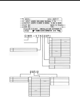
Checking the Nameplate
Example for 3-phase, 200-VAC, 0.1-kW (0.13 HP) Inverter for European standards
Inverter Model |
CIMR-V7AZ20P1 |
20P10 |
|
|
Input Spec. |
|
|
|
|
Output Spec. |
|
|
|
|
Lot No. |
|
|
|
Mass |
Serial No. |
|
|
|
Software Number |
|
|
|
|
|
|
|
|
|
|
Model |
|
|
A |
Z |
Inverter
V7AZ Series
No. Type
A With Digital Operator (with potentiometer)
Note: Contact your OMRON representatives for models without heatsinks.
Specifications
B |
Single-phase 200 VAC |
|
Applicable maximum motor output |
|
2 |
Three-phase 200 VAC |
|
200 V class |
400 V class |
4 |
Three-phase 400 VAC |
0P1 |
0.1 kW |
|
|
|
0P2 |
0.25 kW |
0.37 kW |
|
|
0P4 |
0.55 kW |
0.55 kW |
|
|
0P7 |
1.1 kW |
1.1 kW |
|
|
1P5 |
1.5 kW |
1.5 kW |
|
|
2P2 |
2.2 kW |
2.2 kW |
|
|
3P0 |
|
3.0 kW |
|
|
4P0 |
4.0 kW |
4.0 kW |
|
|
5P5 |
5.5 kW |
5.5 kW |
|
|
7P5 |
7.5 kW |
7.5 kW |
Applicable maximum motor output
|
200 V class |
400 V class |
0P1 |
0.1 kW |
|
0P2 |
0.25 kW |
0.37 kW |
0P4 |
0.55 kW |
0.55 kW |
0P7 |
1.1 kW |
1.1 kW |
1P5 |
1.5 kW |
1.5 kW |
2P2 |
2.2 kW |
2.2 kW |
3P0 |
|
3.0 kW |
4P0 |
4.0 kW |
4.0 kW |
5P5 |
5.5 kW |
5.5 kW |
7P5 |
7.5 kW |
7.5 kW |
No. |
Voltage Class |
|
B |
Single-phase 200 VAC |
|
2 |
Three-phase 200 VAC |
|
4 |
Three-phase 400 VAC |
|
No. |
Specifications |
|
Z |
European standards |
|
No. Protective structure
Open chassis
0(IP20, IP00)*1
Enclosed wall-mounted
1(NEMA1)*2
*1: Inverters with outputs 0P1 to 3P7 are rated IP20. Be sure to remove the top and bottom
covers if using open-chassis mounted Inverters with a 5P5 or 7P5 output.
*2: A NEMA 1 rating is optional for Inverters with outputs 0P1 to 3P7 but standard for 5P5 or 7P5.
Inverter Software Version
The inverter software version can be read out from the monitor parameter U-10 or parameter n179. The parameter shows the last for digits of the software number (e.g. display is“5740”for the software version VSP015740).
The manual describes the functionality of the Inverter software version VSP015740 (0.1 to 4.0 kW) and VSP105750 (5.5 and 7.5 kW). Older software versions do not support all described functions. Check the software version before starting to work with this manual.
19
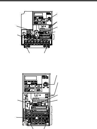
2 Identifying the Parts
Terminal Cover |
Digital Operator |
|
|
||
Wiring Holes |
|
|
for Control Circuit |
Front Cover |
|
|
||
Wiring Holes |
Nameplate |
|
for Main Circuit |
||
|
||
Ground Terminal |
Heatsink |
|
Bottom Cover |
||
Cooling Fan |
|
|
Fan Cover |
|
Digital Operator |
Digital Operator |
Blank cover |
(with potentiometer) |
(without potentiometer) |
In models without a |
JVOP-140 |
JVOP-147 |
Digital Operator, the |
Used for setting or |
Used for setting or |
blank cover is mounted |
changing constants. |
changing constants. |
in place of the Digital |
Frequency can be set |
|
Operator. |
using the potentiometer. |
|
|
20
|
2 Identifying the Parts |
|
V7AZ Inverters with the Covers Removed |
||
|
Frequency-setting Potentiometer |
|
|
Inverter Operation Status Indicators |
|
Input Polarity |
Terminal Resistor Switch for |
|
Switch |
Communication Circuit |
|
|
Voltage/Current Change Switch for |
|
Short-circuit |
Analog Frequency Reference Input |
|
Control Circuit Terminal Block |
||
Bar |
||


 Main Circuit Terminal Block
Ground Terminals
Example for 3-phase (200 V Class, 1.5 kW) Inverter
|
Frequency-setting Potentiometer |
|
Inverter Operation Status Indicators |
|
Terminal Resistor Switch for |
|
Communication Circuit |
Input Polarity |
Voltage/Current Change Switch for |
Switch |
Analog Frequency Reference Input |
|
Control Circuit Terminal Block |
Short-circuit |
Main Circuit Terminal Block |
Bar |
|
|
Ground Terminals |
Example for 3-phase (200 V Class, 0.1 kW) Inverter
21
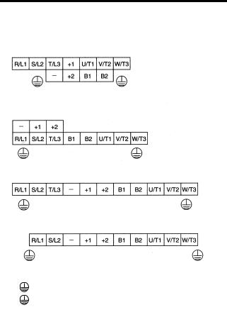
Main Circuit Terminal Arrangement
The terminal arrangement of the main circuit terminals depends on the Inverter model.
CIMR-V7AZ20P1 to 20P7, B0P1 to B0P4
CIMR-V7AZ21P5, 22P2, B0P7, B1P5, 40P2 to 42P2
CIMR-V7AZ24P0, B2P2, 43P0, 44P0
CIMR-V7AZB4P0
CIMR-V7AZ25P5, 27P5, 45P5, 47P5
|
|
|
|
|
|
|
|
|
|
|
|
|
R/L1 |
S/L2 |
T/L3 |
|
+1 |
+2 |
B1 |
B2 |
U/T1 |
V/T2 |
W/T3 |
|
|
|
|
|
|
|
|
|
|
|
|
22

3 Mounting
3 Mounting
Choosing a Location to Mount the Inverter
Be sure the Inverter is protected from the following conditions.
•Extreme cold and heat. Use only within the specified ambient temperature range:
−10 to 50 °C (14 to 122 °F) for IP20 (open chassis type), −10 to 40 °C (14 to 105 °F) for NEMA 1 (TYPE 1)
•Rain and moisture
•Oil sprays and splashes
•Salt spray
•Direct sunlight (Avoid using outdoors.)
•Corrosive gases (e.g., sulfurized gas) or liquids
•Dust or metallic particles in the air
•Physical shock or vibration
•Magnetic noise (Examples: Welding machines, power devices, etc.)
•High humidity
•Radioactive substances
•Combustibles, such as thinner or solvents
23
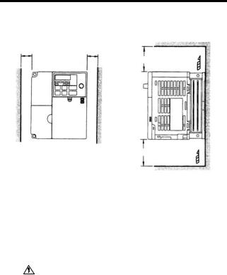
Mounting Dimensions
To mount the V7AZ, the dimensions shown below are required.
a |
a |
Air |
100 mm (3.94 in.) or more
|
|
|
Air |
|
100 mm (3.94 in.) or more |
||
|
|
|
|
Voltage Class |
Max. Applicable |
Length a |
|
Motor Capacity |
|
||
(V) |
|
||
(kW) |
|
|
|
|
|
|
|
200 V Single-phase |
3.7 kW or less |
30 mm (1.18 in.) min. |
|
3-phase |
|
||
400 V 3-phase |
|
|
|
200 V 3-phase |
5.5 kW |
50 mm (1.97 in.) min. |
|
|
|
||
400 V 3-phase |
7.5 kW |
|
|
|
|
||
|
|
|
|
|
|
|
|
CAUTION • |
Lift the Inverter by the heatsinks. When moving the |
||
|
Inverter, never lift it by the plastic case or the termi- |
||
|
nal cover. |
|
|
|
Otherwise, the main unit may fall and be damaged. |
||
• |
The V7AZ generates heat. For effective cooling, |
||
|
mount it vertically. |
||
24
3 Mounting
• The same space is required horizontally and vertically and NOTE right and left for both Open Chassis (IP00, IP20) and
Enclosed Wall-mounted (NEMA 1) Inverters.
•Always remove the top and bottom covers before installing a 200 or 400 V Class Inverter with an output of 5.5/7.5 kW in a panel.
Mounting/Removing Components
Removing and Mounting the Digital Operator and Covers
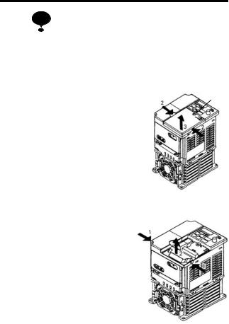
Removing the Front Cover
|
|
|
|
|
|
|
A |
Use a screwdriver to loosen the screw |
1 |
|
|
|
|||
|
|
|
|
|
|
||
|
|
|
|
|
|
|
|
(section A) on the front cover. (To pre- |
|
|
|
|
|
|
|
vent loss, this screw cannot be |
|
|
|
|
|
|
|
removed.) Then press the right and left |
|
2 |
|
|
|
|
|
|
|
1 |
|||||
|
|
|
|
|
|||
sides in direction 1 and lift the front cover in direction 2.
Mounting the Front Cover
Mount the front cover by reversing the order of the above procedure for removal.
Removing the Terminal Cover
• 200 V class Inverters with 1.1 kW and more and all 400 V class Inverters:
After removing the front cover, press the right and left sides of the terminal cover in direction 1 and lift the terminal cover in direction 2.
25
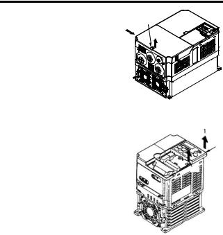
• Inverters of 5.5 and 7.5 kW: |
|
Use a screwdriver to loosen |
B |
the screw (section B) on the |
1 |
terminal cover surface. (To |
2 |
prevent loss, this screw cannot |
|
be removed.) Then press the |
|
right and left sides in direction 1 and lift the terminal cover in direction 2.
Mounting the Terminal Cover
Mount the terminal cover by reversing the order of the above procedure for removal.
Removing the Digital Operator
After removing the front cover, (follow the procedure on page 25) lift the upper and lower sides (section C) of the right side of the Digital Operator in direction 1.
Mounting the Digital Operator
Mount the Digital Operator by reversing the order of the above procedure for removal.
1
C
C
26
3 Mounting
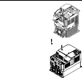
Removing the Bottom Cover
•200 V class Inverters with 1.1 kW and more and all 400 V class Inverters:
After removing the front cover and |
A |
the terminal cover, tilt the bottom |
|
cover in direction 1 with section A |
|
as a supporting point. |
A |
• Inverters of 5.5 and 7.5 kW |
1 |
|
|
After removing the terminal cover, |
1 |
use a screwdriver to loosen the |
|
mounting screw in direction 1. |
|
Mounting the Bottom Cover
Mount the bottom cover by reversing the order of the above procedure for removal.
27

4 Wiring
 WARNING
CAUTION
•Only begin wiring after verifying that the power supply is turned OFF.
Failure to observe this warning may result in an electric shock or a fire.
•Wiring should be performed only by qualified personnel.
Failure to observe this warning may result in an electric shock or a fire.
•When wiring the emergency stop circuit, check the wiring thoroughly before operation.
Failure to observe this warning may result in injury.
•For the 400 V Class, make sure to ground the supply neutral.
Failure to observe this warning may result in an electric shock or a fire.
•Verify that the Inverter rated voltage coincides with the AC power supply voltage.
Failure to observe this caution may result in personal injury or a fire.
•Do not perform a withstand voltage test on the Inverter.
Performing withstand voltage tests may damage semiconductor elements.
•Always tighten terminal screws of the main circuit and the control circuits.
Failure to observe this caution may result in a malfunction, damage, or a fire.
•Never connect the AC main circuit power supply to output terminals U/T1, V/T2, W/T3, B1, B2, -, +1, or +2.
The Inverter will be damaged and the guarantee will be voided.
•Do not connect or disconnect wires or connectors while power is applied to the circuits.
Failure to observe this caution may result in injury.
•Do not perform signal checks during operation.
The machine or the Inverter may be damaged.
•To store a constant with an Enter Command by communications, be sure to take measures for an emergency stop by using the external terminals.
28

4 Wiring
Delayed response may cause injury or damage the machine.
Wiring Instructions
NOTE 1. Always connect the power supply for the main circuit
inputs to the power input terminals R/L1, S/L2, and T/L3 (R/L1, S/L2 for single-phase power) via a molded-case circuit breaker (MCCB) or a fuse. Never connect the power supply to terminals U/T1, V/T2, W/T3, B1, B2, −, +1, or +2. The Inverter may be damaged.
For single-phase Inverters, always use terminals R/L1 and S/L2. Never connect terminal T/L3. Fuses must be of ULclass RK5 fuse or an equivalent.
Refer to page 231 for recommended peripheral devices.
Inverter Power Supply Connection Terminals
200-V 3-phase Input |
200-V Single Input |
400-V 3-phase Input |
Power Supply Speci- |
Power Supply Speci- |
Power Supply Speci- |
fication Inverters |
fication Inverters |
fication Inverters |
CIMR-V7 2 |
CIMR-V7 B |
CIMR-V7 4 |
Connect to R/L1, |
Connect to R/L1 and |
Connect to R/L1, |
S/L2, and T/L3. |
S/L2. |
S/L2, and T/L3. |
|
|
|
2.If the wiring distance between Inverter and motor is long, reduce the Inverter carrier frequency. For details, refer to
Carrier Frequency Selection (n080)14kHz max on page 94.
3.Control wiring must be less than 50 m (164 ft) in length and must be separated from power wiring. Use shielded twisted-pair cable when inputting the frequency signal externally.
4.Only basic insulation to meet the requirements of protection class 1 and overvoltage category II is provided with control circuit terminals. Additional insulation may be necessary in the end product to conform to CE requirements.
5.Closed-loop connectors should be used when wiring to the main circuit terminals.
29
Loading...