


 Loading...
Cat. No. N128-E1-01D
K3HB-S/-X/-V/-H
Digital Indicators
USER’S MANUAL


 Preface
Thank you for purchasing the K3HB.
This manual describes the functions, performance, and application methods needed for optimum use of the K3HB.
Please observe the following items when using the K3HB.
•This product is designed for use by qualified personnel with a knowledge of electrical systems.
•Read this manual carefully and make sure you understand it well to ensure that you are using the K3HB correctly.
•Keep this manual in a safe location so that it is available for reference when required.
Notice
(1)All rights reserved. No part of this manual may be reprinted or copied without the prior written permission of OMRON.
(2)The specifications and other information contained in this manual are subject to change without notice in order to make improvements.
(3)Every precaution has been taken in the preparation of this manual. Nevertheless, OMRON assumes no responsibility for errors or omissions. If you discover any problems with this manual, please notify your nearest OMRON representative, providing them with the catalog number provided on the cover.
I

Read and Understand this Manual
Please read and understand this manual before using the product. Please consult your OMRON representative if you have any questions or comments.
Warranty and Limitations of Liability
WARRANTY
OMRON's exclusive warranty is that the products are free from defects in materials and workmanship for a period of one year (or other period if specified) from date of sale by OMRON.
OMRON MAKES NO WARRANTY OR REPRESENTATION, EXPRESS OR IMPLIED, REGARDING NON-INFRINGEMENT, MERCHANTABILITY, OR FITNESS FOR PARTICULAR PURPOSE OF THE PRODUCTS. ANY BUYER OR USER ACKNOWLEDGES THAT THE BUYER OR USER ALONE HAS DETERMINED THAT THE PRODUCTS WILL SUITABLY MEET THE REQUIREMENTS OF THEIR INTENDED USE. OMRON DISCLAIMS ALL OTHER WARRANTIES, EXPRESS OR IMPLIED.
LIMITATIONS OF LIABILITY
OMRON SHALL NOT BE RESPONSIBLE FOR SPECIAL, INDIRECT, OR CONSEQUENTIAL DAMAGES, LOSS OF PROFITS OR COMMERCIAL LOSS IN ANY WAY CONNECTED WITH THE PRODUCTS, WHETHER SUCH CLAIM IS BASED ON CONTRACT, WARRANTY, NEGLIGENCE, OR STRICT LIABILITY.
In no event shall the responsibility of OMRON for any act exceed the individual price of the product on which liability is asserted.
IN NO EVENT SHALL OMRON BE RESPONSIBLE FOR WARRANTY, REPAIR, OR OTHER CLAIMS REGARDING THE PRODUCTS UNLESS OMRON'S ANALYSIS CONFIRMS THAT THE PRODUCTS WERE PROPERLY HANDLED, STORED, INSTALLED, AND MAINTAINED AND NOT SUBJECT TO CONTAMINATION, ABUSE, MISUSE, OR INAPPROPRIATE MODIFICATION OR REPAIR.
Application Considerations
SUITABILITY FOR USE
OMRON shall not be responsible for conformity with any standards, codes, or regulations that apply to the combination of products in the customer's application or use of the products.
At the customer's request, OMRON will provide applicable third party certification documents identifying ratings and limitations of use that apply to the products. This information by itself is not sufficient for a complete determination of the suitability of the products in combination with the end product, machine, system, or other application or use.
The following are some examples of applications for which particular attention must be given. This is not intended to be an exhaustive list of all possible uses of the products, nor is it intended to imply that the uses listed may be suitable for the products.
•Outdoor use, uses involving potential chemical contamination or electrical interference, or conditions or uses not described in this manual.
•Nuclear energy control systems, combustion systems, railroad systems, aviation systems, medical equipment, amusement machines, vehicles, safety equipment, and installations subject to separate industry or government regulations.
•Systems, machines, and equipment that could present a risk to life or property.
Please know and observe all prohibitions of use applicable to the products.
NEVER USE THE PRODUCTS FOR AN APPLICATION INVOLVING SERIOUS RISK TO LIFE OR PROPERTY WITHOUT ENSURING THAT THE SYSTEM AS A WHOLE HAS BEEN DESIGNED TO ADDRESS THE RISKS, AND THAT THE OMRON PRODUCTS ARE PROPERLY RATED AND INSTALLED FOR THE INTENDED USE WITHIN THE OVERALL EQUIPMENT OR SYSTEM.
PROGRAMMABLE PRODUCTS
OMRON shall not be responsible for the user's programming of a programmable product, or any consequence thereof.
II

Disclaimers
CHANGE IN SPECIFICATIONS
Product specifications and accessories may be changed at any time based on improvements and other reasons.
It is our practice to change model numbers when published ratings or features are changed, or when significant construction changes are made. However, some specifications of the products may be changed without any notice. When in doubt, special model numbers may be assigned to fix or establish key specifications for your application on your request. Please consult with your OMRON representative at any time to confirm actual specifications of purchased products.
DIMENSIONS AND WEIGHTS
Dimensions and weights are nominal and are not to be used for manufacturing purposes, even when tolerances are shown.
PERFORMANCE DATA
Performance data given in this manual is provided as a guide for the user in determining suitability and does not constitute a warranty. It may represent the result of OMRON's test conditions, and the users must correlate it to actual application requirements. Actual performance is subject to the OMRON Warranty and Limitations of Liability.
ERRORS AND OMISSIONS
The information in this document has been carefully checked and is believed to be accurate; however, no responsibility is assumed for clerical, typographical, or proofreading errors, or omissions.
III
Safety Precautions
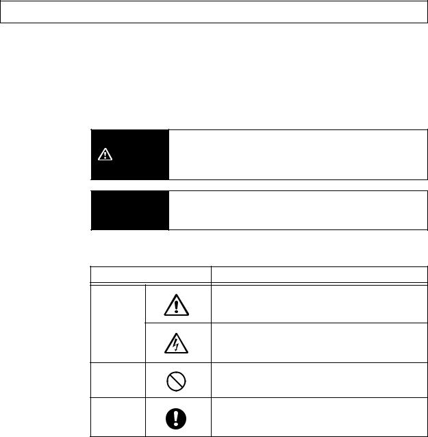
●Definition of Precautionary Information
The following notation is used in this manual to provide precautions required to ensure safe usage of the product.
The safety precautions that are provided are extremely important to safety. Always read and heed the information provided in all safety precautions.
The following notation is used.
Indicates a potentially hazardous situation which, if not
WARNING avoided, will result in minor or moderate injury, or may result in serious injury or death. Additionally there may be
significant property damage.
 CAUTION
●Symbols
Indicates a potentially hazardous situation which, if not avoided, may result in minor or moderate injury or in property damage.
Symbol |
Meaning |
General Caution
Indicates non-specific general cautions, warnings,
and dangers.
Caution
Electrical Shock Caution
Indicates possibility of electric shock under specific conditions.
Prohibition
General Prohibition
Indicates non-specific general prohibitions.
Mandatory
General Caution
Caution
Indicates non-specific general cautions, warnings, and dangers.
IV
●Precautions
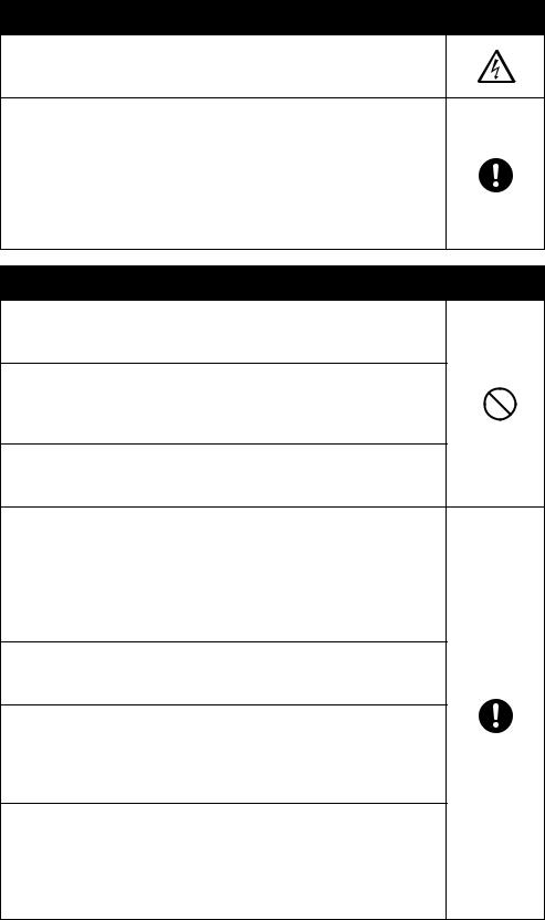
 WARNING
Do not touch the terminals while power is being supplied. Doing so may possibly result in electric shock. Make sure that the terminal cover is installed before using the product.
Always provide protective circuits in the network. Without protective circuits, malfunctions may possibly result in accidents that cause serious injury or significant property damage. Provide double or triple safety measures in external control
circuits, such as emergency stop circuits, interlock circuits, or limit circuits, to ensure safety in the system if an abnormality occurs due to malfunction of the product or another external factor affecting the product's operation.
 CAUTION
Do not allow pieces of metal, wire clippings, or fine metallic shavings or filings from installation to enter the product. Doing so may occasionally result in electric shock, fire, or malfunction.
Do not use the product in locations where flammable or explosive gases are present. Doing so may occasionally result in minor or moderate explosion, causing minor or moderate injury, or property damage.
Do not attempt to disassemble, repair, or modify the product. Doing so may occasionally result in minor or moderate injury due to electric shock.
Do not use the equipment for measurements within Measurement Categories III and IV for K3HB-X and II, III, and IV for K3HB-S, K3HB-V, and K3HB-H (according to IEC61010-1). Doing so may occasionally cause unexpected operation, resulting in minor or moderate injury, or damage to the equipment. Use the equipment for measurements only within the Measurement Category for which the product is designed.
Perform correct setting of the product according to the application. Failure to do so may occasionally cause unexpected operation, resulting in minor or moderate injury, or damage to the equipment.
Ensure safety in the event of product failure by taking safety measures, such as installing a separate monitoring system. Product failure may occasionally prevent operation of comparative outputs, resulting in damage to the connected facilities and equipment.
Tighten the screws on the terminal block and the connector locking screws securely using a tightening torque within the following ranges. Loose screws may occasionally cause fire, resulting in minor or moderate injury, or damage to the equipment. Terminal block screws: 0.43 to 0.58 N·m
Connector locking screws: 0.18 to 0.22 N·m
V

 CAUTION
Make sure that the product will not be adversely affected if the DeviceNet cycle time is lengthened as a result of changing the program with online editing. Extending the cycle time may cause unexpected operation, occasionally resulting in minor or moderate injury, or damage to the equipment.
Before transferring programs to other nodes or changing I/O memory of other nodes, check the nodes to confirm safety. Changing the program or I/O memory of other nodes may occasionally cause unexpected operation, resulting in minor or moderate injury, or damage to the equipment.
VI

Precautions for Safe Use
(1)Do not use the product in the following locations.
•Locations subject to direct radiant heat from heating equipment
•Locations where the product may come into contact with water or oil
•Locations subject to direct sunlight
•Locations where dust or corrosive gases (in particular, sulfuric or ammonia gas) are present
•Locations subject to extreme temperature changes
•Locations where icing or condensation may occur
•Locations subject to excessive shocks or vibration
(2)Do not use the product in locations subject to temperatures or humidity levels outside the specified ranges or in locations prone to condensation. If the product is installed in a panel, ensure that the temperature around the product (not the temperature around the panel) does not go outside the specified range.
(3)Provide sufficient space around the product for heat dissipation.
(4)Use and store the product within the specified temperature and humidity ranges. If several products are mounted side-by-side or arranged in a vertical line, the heat dissipation will cause the internal temperature of the products to rise, shortening the service life. If necessary, cool the products using a fan or other cooling method.
(5)The service life of the output relays depends on the switching capacity and switching conditions. Consider the actual application conditions and use the product within the rated load and electrical service life. Using the product beyond its service life may result in contact welding or burning.
(6)Install the product horizontally.
(7)Mount to a panel between 1 and 8-mm thick.
(8)Use the specified size of crimp terminals (M3, width: 5.8 mm max.) for wiring. To connect bare wires, use AWG22 (cross section: 0.326 mm2) to AWG14 (cross section: 2.081 mm2) to wire the power supply terminals and AWG28 (cross section: 0.081 mm2) to AWG16 (cross section: 1.309 mm2) for other terminals. (Length of exposed wire: 6 to
8 mm)
(9)In order to prevent inductive noise, wire the lines connected to the product separately from power lines carrying high voltages or currents. Do not wire in parallel with or in the same cable as power lines. Other measures for reducing noise include running lines along separate ducts and using shield lines.
(10)Ensure that the rated voltage is achieved no longer than 2 s after turning the power ON.
(11)Allow the product to operate without load for at least 15 minutes after the power is turned ON.
(12)Do not install the product near devices generating strong high-frequency waves or surges. When using a noise filter, check the voltage and current and install it as close to the product as possible.
(13)Do not use thinner to clean the product. Use commercially available alcohol.
(14)Be sure to confirm the name and polarity for each terminal before wiring the terminal block and connectors.
(15)Use the product within the noted supply voltage and rated load.
VII
(16)Do not connect anything to unused terminals.
(17)Output turns OFF when the mode is changed or settings are initialized. Take this into consideration when setting up the control system.
(18)Install an external switch or circuit breaker that complies with applicable IEC60947-1 and IEC60947-3 requirements and label them clearly so that the operator can quickly turn OFF the power.
(19)Use the specified cables for the communications lines and stay within the specified DeviceNet communications distances. Refer to the User's Manual (Cat. No. N129) for details on communications distance specifications and cables.
(20)Do not pull the DeviceNet communications cables with excessive force or bend them past their natural bending radius.
(21)Do not connect or remove connectors while the DeviceNet power is being supplied. Doing so will cause product failure or malfunction.
(22)Use cables with a heat resistance of 70ºC min.
VIII
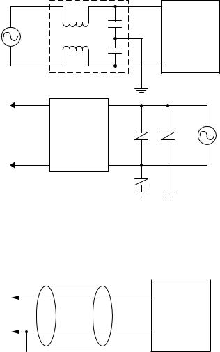
●Noise Countermeasures
Do not install the product near devices generating strong high-frequency waves or surges, such as high-frequency welding and sewing machines.
(1)Mount a surge suppressor or noise filter to peripheral devices generating noise, in particular, motors, transformers, solenoids, and magnet coils.
+
Signal input
-
Line filter
Digital
Indicator
input |
|
supplyPower |
Digital Indicator |
|
Power supply input
Surge suppressor
(2)In order to prevent inductive noise, wire the lines connected to the terminal block separately from power lines carrying high voltages or currents. Do not wire in parallel with or in the same cable as power lines. Other measures for reducing noise include running lines along separate ducts and using shield lines.
Example of Countermeasures for Inductive Noise on Input Lines
+
Digital Indicator
Signal input
-
 2 conductors with shield
(3)If a noise filter is used for the power supply, check the voltage and current, and install the noise filter as close to the product as possible.
(4)Reception interference may occur if the product is used close to a radio, television, or wireless.
IX
●Revision History
The revision code of this manual is given at the end of the catalog number at the bottom left of the back cover.
Cat. No. |
|
N128-E1-01D |
|
|
|
|
|
|
|
|
|
|
|
|
Revision code |
|
Date |
|
Pages and changes |
|
|
|
||
01 |
November 2003 |
Original production |
||
|
|
|
||
01A |
January 2004 |
Page 2-4: Bottom left portion of C corrected. |
||
|
|
|
Page A-5: Information updated for “applicable |
|
|
|
|
standards.” |
|
|
|
|
||
01B |
March 2005 |
Page 1-4: Power interruption memory added. |
||
|
|
|
Page 2-4: Added information on BCD Output |
|
|
|
|
Cable at bottom of page. |
|
|
|
|
Pages 2-4, A-11, and A-17: Changed K34-B4 to |
|
|
|
|
K34-BCD. |
|
|
|
|
Pages 2-5: Added information on Special Cable |
|
|
|
|
(for Event Inputs with 8-pin Connector) at bottom |
|
|
|
|
of page. |
|
|
|
|
Page 2-7: “Min.” changed to “max.” at bottom of |
|
|
|
|
page. |
|
|
|
|
Page 2-12: Corrected the maximum |
|
|
|
|
measurement range of input range B for DC |
|
|
|
|
voltage. |
|
|
|
|
Page 2-13: Changed K2HB-V to K3HB-V in |
|
|
|
|
heading. |
|
|
|
|
Page 5-29: Underlined the phrase in the first line |
|
|
|
|
of the page to draw user’s attention. |
|
|
|
|
Page 5-83: Text added after table. |
|
|
|
|
Page 6-9: Middle rows of table reversed. |
|
|
|
|
Pages A-2: Changed “XAD” to “XVA” and “XVA” |
|
|
|
|
to “XAD” in left column. |
|
|
|
|
Page A-3: Changed column division within table |
|
|
|
|
under Event inputs, i.e., Startup compensation |
|
|
|
|
timer input was moved to the same column as for |
|
|
|
|
the Hold input. |
|
|
|
|
Page A-3: Changed “max.” to “min.” for the load |
|
|
|
|
resistance specification of the linear output. |
|
|
|
|
Page A-10: Added information on BCD to table 4. |
|
|
|
|
||
01C |
December 2006 |
Page 2-13: Corrected model number in heading. |
||
|
|
|
Page 5-85: Added values for the upper and lower |
|
|
|
|
limits and corrected those for the present value in |
|
|
|
|
the bottom table. |
|
|
|
|
Page 6-9: Corrected second and third cells in |
|
|
|
|
Input column. |
|
|
|
|
Page A-2: Corrected third and fourth cells in |
|
|
|
|
Absolute max. ratings of inputs column. |
|
|
|
|
Page A-16: Corrected capitalization in first four |
|
|
|
|
cells in Characters column. |
|
|
|
|
||
01D |
April 2007 |
Page 6-9: Corrected second and third cells in |
||
|
|
|
Input column. |
|
|
|
|
Page A-2: Corrected third and fourth cells in |
|
|
|
|
Absolute max. ratings of inputs column. |
|
|
|
|
|
|
X


 About this Manual
Manual Structure
Preface
Provides precautionary information, a manual revision history, an overview of the manual contents, information on using this manual, and other general information.
Section 1 Outline
Provides an overview and describes the features of the product.
Section 2 Preparations
Describes the mounting and wiring required before using the product.
Section 3 Basic Application Methods
Shows typical applications for the product. Also shows wiring and parameter settings which enables the user to understand how to use the product from practical examples.
Section 4 Initial Setup
Describes the initial setup process when using this product.
Section 5 Functions and Operations
Describes the functions and settings methods for more effective use of functions, displays, outputs, and settings for each application.
Section 6 User Calibration
Describes the methods for user calibration.
Section 7 Troubleshooting
Describes how to check and possible countermeasures for errors.
Appendices
Provides specifications and settings lists.
XI

●Settings Data Notation
The letters of the alphabet in settings data are displayed as shown below.
a |
b |
c |
d |
e |
f |
g |
h |
i |
j |
k |
l |
m |
|
|
|
|
|
|
|
|
|
|
|
|
|
A |
B |
C |
D |
E |
F |
G |
H |
I |
J |
K |
L |
M |
|
|
|
|
|
|
|
|
|
|
|
|
|
|
|
|
|
|
|
|
|
|
|
|
|
|
n |
o |
p |
q |
r |
s |
t |
u |
v |
w |
x |
y |
z |
|
|
|
|
|
|
|
|
|
|
|
|
|
N |
O |
P |
Q |
R |
S |
T |
U |
V |
W |
X |
Y |
Z |
|
|
|
|
|
|
|
|
|
|
|
|
|
●Applicable Model Notation
The following symbols are used to indicate the applicable models for specific functions.
 X
X K3HB-X@@
 V
V K3HB-V@@
 H
H K3HB-H@@
 S
S K3HB-S@@
XII

Contents
CONTENTS
Section 1 Outline
1.1 |
Main Functions and Features of the K3HB . . . . . . . . . . . . . . . . . . . . . . . . . . . . . . . . . . . . |
1-2 |
1.2 |
Component Names and Functions . . . . . . . . . . . . . . . . . . . . . . . . . . . . . . . . . . . . . . . . . . . |
1-5 |
1.3 |
Internal Block Diagram. . . . . . . . . . . . . . . . . . . . . . . . . . . . . . . . . . . . . . . . . . . . . . . . . . . . |
1-6 |
Section 2 Preparations
2.1 |
Mounting. . . . . . . . . . . . . . . . . . . . . . . . . . . . . . . . . . . . . . . . . . . . . . . . . . . . . . . . . . . . . . . |
2-2 |
2.2 |
Using I/O. . . . . . . . . . . . . . . . . . . . . . . . . . . . . . . . . . . . . . . . . . . . . . . . . . . . . . . . . . . . . . . |
2-4 |
Section 3 Basic Application Methods
3.1 |
Monitoring Tank Levels . . . . . . . . . . . . . . . . . . . . . . . . . . . . . . . . . . . . . . . . . . . . . . . . . . . |
3-2 |
3.2 |
Monitoring Motor Load Current. . . . . . . . . . . . . . . . . . . . . . . . . . . . . . . . . . . . . . . . . . . . . |
3-6 |
3.3 |
Weighing Material. . . . . . . . . . . . . . . . . . . . . . . . . . . . . . . . . . . . . . . . . . . . . . . . . . . . . . . . |
3-9 |
3.4 |
Temperature Monitoring/Control with Multi-level Output. . . . . . . . . . . . . . . . . . . . . . . . . |
3-11 |
3.5 |
Product Height Measurement and OK/NG Judgement. . . . . . . . . . . . . . . . . . . . . . . . . . . . |
3-14 |
3.6 |
Panel Thickness Inspection. . . . . . . . . . . . . . . . . . . . . . . . . . . . . . . . . . . . . . . . . . . . . . . . . |
3-17 |
3.7 |
Measurement of Disk Eccentricity . . . . . . . . . . . . . . . . . . . . . . . . . . . . . . . . . . . . . . . . . . . |
3-20 |
3.8 |
Step Inspection . . . . . . . . . . . . . . . . . . . . . . . . . . . . . . . . . . . . . . . . . . . . . . . . . . . . . . . . . . |
3-22 |
Section 4 Initial Setup
4.1 |
K3HB-X Initial Setup Example (K3HB-XVD) . . . . . . . . . . . . . . . . . . . . . . . . . . . . . . . . . |
4-2 |
4.2 |
K3HB-V Initial Setup Example (K3HB-VLC). . . . . . . . . . . . . . . . . . . . . . . . . . . . . . . . . . |
4-4 |
4.3 |
K3HB-H Initial Setup Example (K3HB-HTA). . . . . . . . . . . . . . . . . . . . . . . . . . . . . . . . . . |
4-6 |
4.4 |
K3HB-S Initial Setup Example (K3HB-SSD) . . . . . . . . . . . . . . . . . . . . . . . . . . . . . . . . . . |
4-8 |
Section 5 Functions and Operations
Knowledge Required for Setting Parameters . . . . . . . . . . . . . . . . . . . . . . . . . . . . . . . . . . . . . . . . |
5-2 |
|
-----Operation Adjustments ------------------------------------------------------------------------------ |
|
|
5.1 |
Setting Calculations . . . . . . . . . . . . . . . . . . . . . . . . . . . . . . . . . . . . . . . . . . . . . . . . . . . . . . |
5-9 |
5.2 |
Setting Input Types . . . . . . . . . . . . . . . . . . . . . . . . . . . . . . . . . . . . . . . . . . . . . . . . . . . . . . . |
5-11 |
5.3 |
Setting Scaling Values. . . . . . . . . . . . . . . . . . . . . . . . . . . . . . . . . . . . . . . . . . . . . . . . . . . . . |
5-14 |
5.4 |
Setting the Temperature Unit . . . . . . . . . . . . . . . . . . . . . . . . . . . . . . . . . . . . . . . . . . . . . . . |
5-18 |
5.5 |
Setting Measurement Operations . . . . . . . . . . . . . . . . . . . . . . . . . . . . . . . . . . . . . . . . . . . . |
5-19 |
5.6 |
Shifting the Temperature Input . . . . . . . . . . . . . . . . . . . . . . . . . . . . . . . . . . . . . . . . . . . . . . |
5-24 |
5.7 |
Resetting Measurements . . . . . . . . . . . . . . . . . . . . . . . . . . . . . . . . . . . . . . . . . . . . . . . . . . . |
5-26 |
5.8 |
Not Performing Measurements for Set Intervals . . . . . . . . . . . . . . . . . . . . . . . . . . . . . . . . |
5-27 |
Contents
CONTENTS-1

Contents
Contents
---- Input Adjustments ------------------------------------------------------------------------------------ |
|
|
5.9 |
Selecting Operations for Input Errors. . . . . . . . . . . . . . . . . . . . . . . . . . . . . . . . . . . . . . . . . . |
5-29 |
5.10 |
Disabling Cold Junction Compensation . . . . . . . . . . . . . . . . . . . . . . . . . . . . . . . . . . . . . . . . |
5-31 |
5.11 |
Adjusting Timing Inputs. . . . . . . . . . . . . . . . . . . . . . . . . . . . . . . . . . . . . . . . . . . . . . . . . . . . |
5-33 |
5.12 |
Eliminating Drift Near “0” . . . . . . . . . . . . . . . . . . . . . . . . . . . . . . . . . . . . . . . . . . . . . . . . . . |
5-36 |
5.13 |
Averaging Inputs. . . . . . . . . . . . . . . . . . . . . . . . . . . . . . . . . . . . . . . . . . . . . . . . . . . . . . . . . . |
5-38 |
5.14 |
Detecting Sudden Input Changes . . . . . . . . . . . . . . . . . . . . . . . . . . . . . . . . . . . . . . . . . . . . . |
5-41 |
---- Output Adjustments ---------------------------------------------------------------------------------- |
|
|
5.15 |
Changing Comparative Output Patterns . . . . . . . . . . . . . . . . . . . . . . . . . . . . . . . . . . . . . . . . |
5-44 |
5.16 |
Preventing Output Chattering . . . . . . . . . . . . . . . . . . . . . . . . . . . . . . . . . . . . . . . . . . . . . . . . |
5-46 |
5.17 |
Outputting for a Set Interval . . . . . . . . . . . . . . . . . . . . . . . . . . . . . . . . . . . . . . . . . . . . . . . . . |
5-49 |
5.18 |
Delaying Output OFF Timing . . . . . . . . . . . . . . . . . . . . . . . . . . . . . . . . . . . . . . . . . . . . . . . |
5-52 |
5.19 |
Holding Measurement Status . . . . . . . . . . . . . . . . . . . . . . . . . . . . . . . . . . . . . . . . . . . . . . . . |
5-54 |
5.20 |
Holding Comparative Outputs . . . . . . . . . . . . . . . . . . . . . . . . . . . . . . . . . . . . . . . . . . . . . . . |
5-55 |
5.21 |
Allocating Another Output to PASS Output. . . . . . . . . . . . . . . . . . . . . . . . . . . . . . . . . . . . . |
5-57 |
5.22 |
Reversing Output Logic . . . . . . . . . . . . . . . . . . . . . . . . . . . . . . . . . . . . . . . . . . . . . . . . . . . . |
5-59 |
5.23 |
No Output before PASS Range. . . . . . . . . . . . . . . . . . . . . . . . . . . . . . . . . . . . . . . . . . . . . . . |
5-61 |
5.24 |
Performing Linear Output . . . . . . . . . . . . . . . . . . . . . . . . . . . . . . . . . . . . . . . . . . . . . . . . . . |
5-63 |
---- Display Adjustments---------------------------------------------------------------------------------- |
|
|
5.25 |
Setting the Present Measurement Value to “0”. . . . . . . . . . . . . . . . . . . . . . . . . . . . . . . . . . . |
5-65 |
5.26 |
Setting the Present Measurement Value to “0” Again when Using a Forced Zero . . . . . . . |
5-67 |
5.27 |
Compensating Forced-zero References . . . . . . . . . . . . . . . . . . . . . . . . . . . . . . . . . . . . . . . . |
5-70 |
5.28 |
Changing Display Refresh Periods. . . . . . . . . . . . . . . . . . . . . . . . . . . . . . . . . . . . . . . . . . . . |
5-73 |
5.29 |
Holding Maximum and Minimum Values . . . . . . . . . . . . . . . . . . . . . . . . . . . . . . . . . . . . . . |
5-75 |
5.30 |
Changing Normal Display Values to Maximum and Minimum Values . . . . . . . . . . . . . . . . |
5-78 |
5.31 |
Setting the Step for Changing the Rightmost Digit . . . . . . . . . . . . . . . . . . . . . . . . . . . . . . . |
5-80 |
5.32 |
Displaying/Not Displaying Comparative Set Values . . . . . . . . . . . . . . . . . . . . . . . . . . . . . . |
5-82 |
5.33 |
Changing Display Colors . . . . . . . . . . . . . . . . . . . . . . . . . . . . . . . . . . . . . . . . . . . . . . . . . . . |
5-83 |
5.34 |
Using the Position Meter . . . . . . . . . . . . . . . . . . . . . . . . . . . . . . . . . . . . . . . . . . . . . . . . . . . |
5-85 |
5.35 |
Automatic Return to Normal Display. . . . . . . . . . . . . . . . . . . . . . . . . . . . . . . . . . . . . . . . . . |
5-88 |
5.36 |
No Decimal Point Display . . . . . . . . . . . . . . . . . . . . . . . . . . . . . . . . . . . . . . . . . . . . . . . . . . |
5-90 |
---- Other Operations-------------------------------------------------------------------------------------- |
|
|
5.37 |
Performing Output Tests. . . . . . . . . . . . . . . . . . . . . . . . . . . . . . . . . . . . . . . . . . . . . . . . . . . . |
5-92 |
5.38 |
Using Comparative Set Value Banks . . . . . . . . . . . . . . . . . . . . . . . . . . . . . . . . . . . . . . . . . . |
5-93 |
5.39 |
Copying Bank Comparative Set Values . . . . . . . . . . . . . . . . . . . . . . . . . . . . . . . . . . . . . . . . |
5-98 |
5.40 |
Initializing All Settings. . . . . . . . . . . . . . . . . . . . . . . . . . . . . . . . . . . . . . . . . . . . . . . . . . . . . |
5-100 |
5.41 |
Limiting Key Operations . . . . . . . . . . . . . . . . . . . . . . . . . . . . . . . . . . . . . . . . . . . . . . . . . . . |
5-102 |
Section 6 User Calibration
6.1 |
About User Calibration. . . . . . . . . . . . . . . . . . . . . . . . . . . . . . . . . . . . . . . . . . . . . . . . . . . . . |
6-2 |
6.2 |
User Calibration Operation. . . . . . . . . . . . . . . . . . . . . . . . . . . . . . . . . . . . . . . . . . . . . . . . . . |
6-5 |
CONTENTS-2

Contents
Section 7 Troubleshooting
7.1 |
Error Displays . . . . . . . . . . . . . . . . . . . . . . . . . . . . . . . . . . . . . . . . . . . . . . . . . . . . . . . . . . . |
7-2 |
7.2 |
Countermeasures. . . . . . . . . . . . . . . . . . . . . . . . . . . . . . . . . . . . . . . . . . . . . . . . . . . . . . . . . |
7-3 |
Appendices
Specifications . . . . . . . . . . . . . . . . . . . . . . . . . . . . . . . . . . . . . . . . . . . . . . . . . . . . . . . . . . . . . . . . . |
A-2 |
Model Number Structure . . . . . . . . . . . . . . . . . . . . . . . . . . . . . . . . . . . . . . . . . . . . . . . . . . . . . . . . |
A-9 |
Parameter List . . . . . . . . . . . . . . . . . . . . . . . . . . . . . . . . . . . . . . . . . . . . . . . . . . . . . . . . . . . . . . . . . |
A-12 |
Parameter Display Conditions . . . . . . . . . . . . . . . . . . . . . . . . . . . . . . . . . . . . . . . . . . . . . . . . . . . . |
A-17 |
About Parameters . . . . . . . . . . . . . . . . . . . . . . . . . . . . . . . . . . . . . . . . . . . . . . . . . . . . . . . . . . . . . . |
A-18 |
Sampling and Comparative Output Response Times . . . . . . . . . . . . . . . . . . . . . . . . . . . . . . . . . . . |
A-26 |
No Measurement Status . . . . . . . . . . . . . . . . . . . . . . . . . . . . . . . . . . . . . . . . . . . . . . . . . . . . . . . . . |
A-30 |
Contents
CONTENTS-3

Contents
Contents
CONTENTS-4

Section 1 Outline
1.1 |
Main Functions and Features of the K3HB ................................ |
1-2 |
1.2 |
Component Names and Functions ............................................ |
1-5 |
1.3 |
Internal Block Diagram .............................................................. |
1-6 |
Outline
1-1

Outline
Section 1 Outline
1.1 Main Functions and Features of the K3HB
Measurement
Input calculation
Two measurement values can be added, subtracted, or the ratio calculated. In addition, any constant can be set and measurement values can be added to or subtracted from a constant.
→ P.5-9
S
Filter
Average processing
Average processing of input signals with extreme changes or noise smooths out the display and makes control stable.
→ P.5-38
X V S H
Input compensation
Forced-zero
Forces the present value to 0. Effective to set a reference value from which to perform measurements.
→ P.5-65 |
X V S |
|
Zero-limit
Changes the display value to 0 for input values less than the set value.
Effective when drift and displacement of values near zero need to be eliminated.
→ P.5-36
X V S
Timing hold
Using external timing signal inputs, synchronous measurements can be made and maximum values, minimum values, and the difference between maximum and minimum values can be measured.
→ P.5-18
X V S H
Previous average value comparison
Slight changes can be removed from input signals to detect only extreme changes.
→ P.5-41
X V S H
Tare zero
Shifts the current value measured with a forced zero to 0 again.
Effective, for example, when two compounds are measured separately.
→ P.5-67
X V S
Step value
Sets the step size for changing the value of the rightmost digit of the measurement value.
→ P.5-80
X V S H
Timing delay
The start and stop timing for measurements can be adjusted using timing signals.
→ P.5-33
X V S H
Zero-trimming
Compensates for gradual changes in input signals from, for example, sensor temperature drift, based on OK data (PASS data) at measurement.
→ P.5-70
X V S
Temperature input shift
Shifts the temperature input value.
→ P.5-24
H
1-2

1.1 Main Functions and Features of the K3HB
Key operations
Teaching
During scaling, the input value during measurement can be set, as is, as the scaling input value.
→ P.5-14
X V S
(Setting Scaling)
Key protection
Limits key-operated level and parameter changes to prevent inadvertent key operations and malfunctions.
→ P.5-102
Outputs
Comparative output pattern
The comparative output pattern can be selected as standard output, zone output, and level output.
→ P.5-44
X V S H
PASS output change
Comparative results other than PASS and error signals can be output from the PASS output terminal.
→ P.5-57
X V S H
Output logic
Reverses the output logic of comparative outputs for comparative results.
→ P.5-59
X V S H
Linear output
Outputs currents or voltages proportional to measurement values as they change.
→ P.5-65
Hysteresis
Prevents comparative output chattering when the measurement value fluctuates slightly near the set value.
→ P.5-46
X V S H
Output OFF delay
Connects the comparative output OFF timing for a set interval. Comparative output ON times can be held when comparative results change quickly.
→ P.5-55
Startup compensation timer
Constant-time measurements can be stopped by an external signal input.
→ P.5-27
X V S H
Standby sequence
Turns the comparative output OFF until the measurement value enters the PASS range. → P.5-61 


Output refresh stop
Holds the output status when comparative results outputs other than PASS turn ON.
→ P.5-52
X V S H
Shot output
Produces a constant comparative output ON time.
→ P.5-49
X V S H
Output test
Output operation can be confirmed without actual input signals, by setting test measurement values using the keys.
→ P.5-90
Outline
1-3
Outline
Section 1 Outline
Display
Display value selection |
|
Display color selection |
Display refresh period |
||||
The current display value can |
The PV display color can be |
When inputs change quickly, |
|||||
be selected from the present |
set to either green or red. The |
the display refresh period can |
|||||
value, the maximum value, |
|
present value color can be |
be delayed to reduce |
||||
and the minimum value. |
|
switched according to the |
flickering and make the |
||||
|
|
|
status of comparative outputs. |
display easier to read. |
|||
→ P.5-78 |
X V S H |
→ P.5-83 |
X V S H |
→ P.5-73 |
X V S H |
||
|
|
|
|||||
Position meter |
|
|
Scaling |
|
|
Comparative set value display |
|
Displays the current |
|
Can convert the input signal to |
The comparative set value |
||||
measurement value as a position |
any display value. |
|
can be set to not display |
||||
in relation to the scaling width on |
|
|
|
during operation. |
|||
a meter with 20 sections. |
|
|
|
|
|
|
|
→ P.5-85 |
X V S H |
→ P.5-14 |
|
X V S |
→ P.5-82 |
X V S H |
|
|
|
|
|
||||
Decimal point display |
|
|
|
|
|
|
|
Disables displaying numerals |
|
|
|
|
|
||
the decimal point in |
|
|
|
|
|
|
|
measurement values. |
|
|
|
|
|
|
|
→ P.5-93 |
|
H |
|
|
|
|
|
|
|
|
|
|
|
|
|
Other |
|
|
|
|
|
|
|
Max/Min hold |
|
|
Bank selection |
|
Bank copy |
|
|
Holds the maximum and |
|
Eight comparative set value |
Any bank setting can be |
||||
minimum measurement |
|
banks can be selected using |
copied to all banks. |
||||
values. |
|
|
the keys on the front of the |
|
|
||
|
|
|
Unit or by external inputs. |
|
|
||
|
|
|
Groups of comparative set |
|
|
||
|
|
|
values can be set and can be |
|
|
||
|
|
|
selected as groups. |
|
|
|
|
→ P.5-54 |
X V S H |
→ P.5-93 |
X V S H |
→ P.5-98 |
X V S H |
||
|
|
|
|||||
Cold junction |
|
|
User calibration |
|
Power interruption memory |
||
compensation |
|
|
|
|
|
|
|
Enables or disables terminal |
Allows the user to calibrate the |
Enables recording the |
|||||
temperature compensation. |
K3HB. |
|
|
maximum and minimum |
|||
→ P.5-31 |
|
H |
→ P.6-1 |
X V S H |
values when power is |
||
|
|
|
interrupted. |
|
|||
|
|
|
|
|
|
|
|
→ P.5-75
X V S H
1-4
1.2 Component Names and Functions
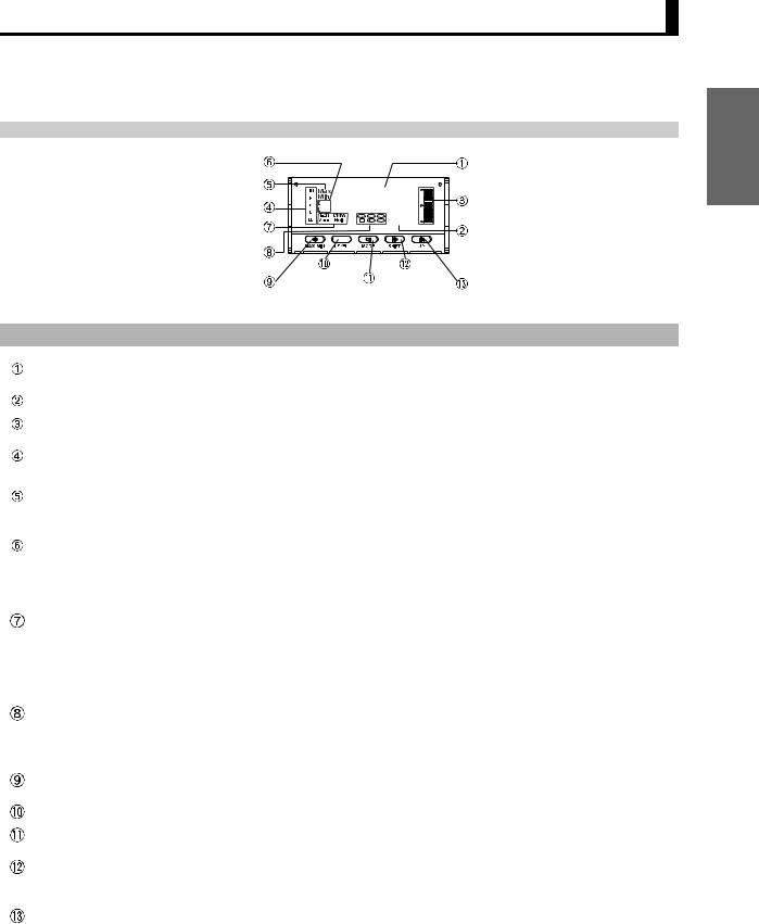
1.2 Component Names and Functions
|
|
Level/bank display |
|
|
|
|
|
|
|
|
|
PV display |
|
|
|
|
Max/Min status |
|
|
888888 |
|
|
Position meter |
||||
|
|
|
|
|
|
|
|||||||
|
Comparative output status |
|
|
|
|
||||||||
|
|
|
|||||||||||
|
|
|
|
|
|||||||||
|
|
|
|
||||||||||
|
|
|
|
||||||||||
|
|
|
Status indicators |
|
|
|
88888 |
|
|
SV display |
|||
|
|
|
|
|
|
||||||||
|
|
|
|
|
|
|
|
|
|
|
|
||
|
|
|
SV display status |
|
|
|
|
|
|
|
|
|
|
|
|
|
MAX/MIN Key |
LEVEL Key |
|
SHIFT Key |
UP Key |
||||||
|
|
|
|
|
MODE Key |
||||||||
|
|
|
|
|
|
|
|||||||
|
|
|
|
|
|
|
|
|
|
|
|
|
|
No. |
Name |
|
|
|
|
|
|
|
|
Function |
|
||
|
|
|
|
|
|
|
|
|
|
|
|||
|
|
|
|
|
|
|
|
|
|
|
|||
|
PV display |
|
Displays PVs, maximum values, minimum values, parameter names, and |
||||||||||
|
|
|
error names. |
|
|
|
|
|
|
|
|
|
|
|
|
|
|
|
|
|
|
|
|
|
|
||
|
SV display |
|
Displays SVs and monitor values. |
|
|||||||||
|
|
|
|
|
|
|
|
|
|
|
|||
|
Position meter |
|
Displays the position of the PV with respect to a desired scale. |
||||||||||
|
|
|
|
|
|
|
|
|
|
|
|
||
|
Comparative output |
|
Display the status of comparative outputs. |
|
|||||||||
|
status indicators |
|
|
|
|
|
|
|
|
|
|
|
|
|
|
|
|
|
|
|
|
|
|
|
|||
|
Max/Min status |
|
Turns ON when the maximum value or minimum value is displayed in the |
||||||||||
|
indicator |
|
RUN level. |
|
|
|
|
|
|
|
|
|
|
|
|
|
|
|
|
|
|
|
|
|
|||
|
Level/bank display |
|
In RUN level, displays the bank if the bank function is ON. (Turns OFF if the |
||||||||||
|
|
|
bank function is OFF.) |
|
|
|
|
|
|
|
|||
|
|
|
In other levels, displays the current level. |
|
|||||||||
|
|
|
|
|
|
|
|
|
|
|
|||
|
Status indicators |
|
T-ZR: Turns ON when the tare zero function is executed. Turns OFF if it is |
||||||||||
|
|
|
not executed or is cleared. |
|
|||||||||
|
|
|
Zero: Turns ON when the forced-zero function is executed. Turns OFF if it |
||||||||||
|
|
|
is not executed or is cleared. (Excluding the K3HB-H.) |
||||||||||
|
|
|
Hold: Turns ON/OFF when hold input turns ON/OFF. |
||||||||||
|
|
|
|
|
|
|
|
|
|
|
|||
|
SV display status |
|
TG: Turns ON when the timing signal turns ON. Otherwise OFF. |
||||||||||
|
indicators |
|
T: Turns ON when parameters for which teaching can be performed are |
||||||||||
|
|
|
displayed. |
|
|
|
|
|
|
|
|||
|
|
|
HH, H, L, LL: In RUN level, turn ON when the comparative set values HH, |
||||||||||
|
|
|
|
H, L, and LL are displayed. |
|
||||||||
|
|
|
|
|
|
|
|
|
|
|
|||
|
MAX/MIN Key |
|
Used to switch the display between the PV, maximum value, and minimum |
||||||||||
|
|
|
value and to reset the maximum and minimum values. |
||||||||||
|
|
|
|
|
|
|
|
|
|
|
|
|
|
|
LEVEL Key |
|
Used to switch level. |
|
|
|
|
|
|
|
|||
|
|
|
|
|
|
|
|
|
|
|
|
||
|
MODE Key |
|
Used to switch the parameters displayed. |
|
|||||||||
|
|
|
|
|
|
|
|
|
|
|
|
||
|
SHIFT Key |
|
Used to change parameter settings. |
|
|||||||||
|
|
|
When changing a set value, this key is used to move along the digits. |
||||||||||
|
|
|
|
|
|
|
|
|
|
|
|||
|
UP Key |
|
When changing a set value, this key is used to change the actual value. |
||||||||||
|
|
|
When a measurement value is displayed, this key is used to execute or |
||||||||||
|
|
|
clear the forced-zero function or to execute teaching. |
||||||||||
|
|
|
|
|
|
|
|
|
|
|
|
|
|
Outline
1-5
Outline
Section 1 Outline
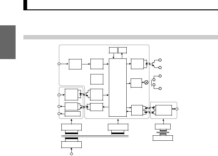
1.3 Internal Block Diagram
|
|
Key |
Display |
|
|
|
Analog input |
Input |
AD |
|
Drive |
Transistor |
|
circuit |
converter |
|
circuit |
output |
|
|
terminal |
|
|
||||
|
|
Microcomputer |
|
|
|
|
|
|
EEPROM |
Drive |
Contact |
|
|
|
|
|
|
circuit |
outputs |
|
|
Event |
Wave- |
|
|
|
|
Event input |
input |
shaping |
|
|
|
|
terminal |
circuit |
circuit |
|
|
|
|
Linear output |
Linear output |
Drive |
|
|
|
Communications |
circuit |
|
Drive |
Communications |
|||
|
circuit |
|
terminal |
|||
Sensor power |
Filter |
|
|
circuit |
driver |
|
|
|
|
||||
|
|
|
|
|
||
supply |
|
|
|
|
|
|
|
Constant voltage |
Constant voltage |
|
Constant voltage |
|
|
|
circuit 1 |
circuit 2 |
|
circuit 3 |
|
|
|
|
|
|
|
Constant voltage |
|
|
|
|
|
|
circuit 1 |
|
|
Power supply |
|
|
|
|
|
|
circuit |
|
|
|
|
|
Operating power supply |
|
|
|
|
|
|
1-6

Section 2 Preparations
2.1 |
Mounting .................................................................................... |
2-2 |
2.2 |
Using I/O.................................................................................... |
2-4 |
2-1
Preparations
Section 2 Preparations
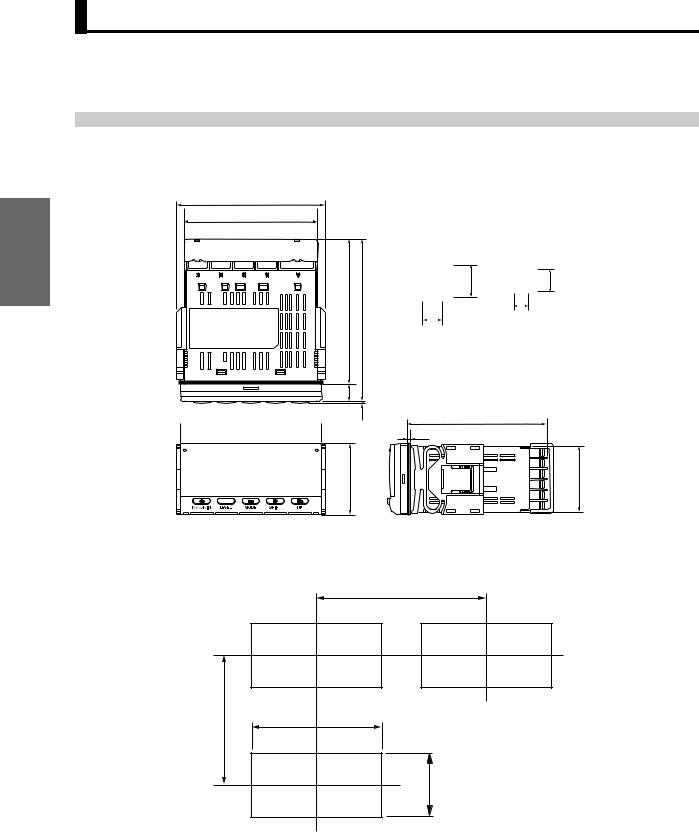
2.1 Mounting
Preparations
■ External Dimensions
101.2 |
|
|
|
|
|
91 |
|
|
|
|
|
|
|
Character size for main display (mm) |
|||
|
|
PV display |
SV display |
||
|
(112) |
8 |
14.2 |
8 |
4.9 |
100 |
|
|
2.6 |
|
|
|
|
|
|
|
|
|
|
7.6 |
|
|
|
|
12 |
|
96 |
1.3 |
95 (DeviceNet models: 97) |
|
|
2 |
|
48 |
44.8 |
■ Panel Cutout Dimensions
120 min.
75 min.
92 +0-0.8
+0.6 45-0
2-2
2.1 Mounting
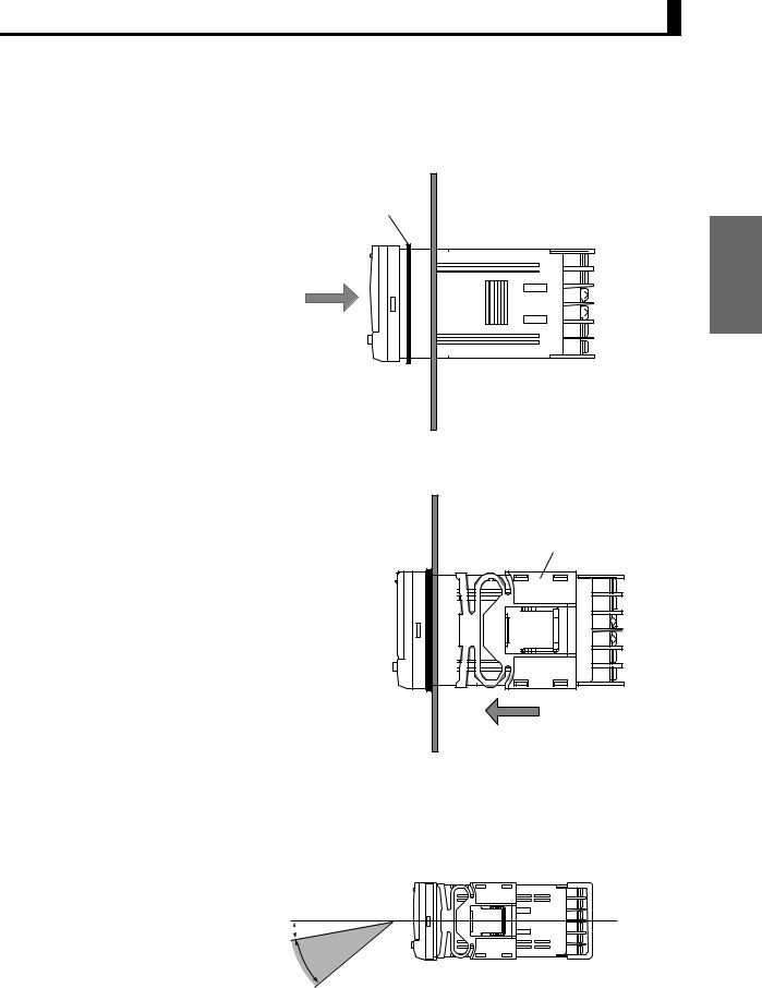
■ Mounting Method
(1)Insert the K3HB into the mounting cutout in the panel.
(2)Insert watertight packing around the Unit to make the mounting watertight.
Watertight packing
Preparations
(3)Insert the adapter into the grooves on the left and right sides of the rear case and push until it reaches the panel and is fixed in place.
Adapter |
■ LCD Field of Vision
The K3HB is designed to have the best visibility at the angles shown in the following diagram.
 10˚
10˚
30˚
2-3

Preparations
Section 2 Preparations
2.2 Using I/O
A
Operating Power Supply
100 to 240 VAC
24 VAC/ VDC
*Check the required power supply type.
|
B |
|
|
Sensor Power |
Supply/Output |
||
Sensor power supply + |
Sensor power supply + |
||
PASS output |
|
|
linear output |
|
|
|
A01 |
|
V01 |
|
|
|
|
|
-0/5 -1 |
CN/ |
-0/5 -1 |
C/N |
|
|
|
|
/5 |
|
/5 |
|
|
VDC10100 mA |
12VDC80mAC/N |
powerSensorsupply |
-0 C/N |
m0-20/4-20A10VDC100mA |
12VDC80mAN/C0- |
Am0 2-4 /02 |
Sensorpower supply |
100VDC10 mA |
80VDC12mA |
||||||
|
|
|
|
|
|
-0 |
|
<K33- |
<K33- |
|
<K33- <K33- |
<K33- |
<K33- |
|
|
CPB> |
CPA> |
|
L2B> |
L1B> |
L2A> |
L1A> |
|
Sensor power supply
|
|
CN/ |
10 VDC 100 mA |
12 VDC 80 mA |
Sensor power supply |
<K33-B> <K33-A>
Sensor power supply + communications
|
|
|
|
|
|
|
|
|
|
|
|
|
|
B(+) |
|
DS |
|
B(+) |
|
DS |
|
||||
|
A(-) |
|
DR |
|
A(-) |
|
DR |
|
||||
|
B(+) |
|
GS |
|
B(+) |
|
GS |
supply |
||||
|
A(-) |
|
C/N |
|
A(-) |
|
C/N |
|||||
|
VDC 100 mA |
|
VDC 100 mA |
|
VDC 80 mA |
|
VDC 80 mA |
|
|
|
|
Sensor power |
|
|
|
|
|
|
|
|
|||||
|
|
|
|
|
|
|
|
|||||
|
10 |
|
10 |
|
12 |
|
12 |
|
|
|
|
|
|
|
|
|
|
|
|
|
|
|
|
|
|
|
|
RS-232C |
RS-232C |
|
||||||||
|
|
<K33- |
|
|
<K33- |
|
||||||
|
|
FLK1B> |
|
|
FLK1A> |
|
||||||
RS-485 |
RS-485 |
|
||||||||||
<K33- |
|
|
<K33- |
|
|
|
|
|
|
|
||
FLK3B> |
FLK3A> |
|
||||||||||
A |
B |
C |
D |
E |
1 |
|
|
|
|
2 |
|
|
|
|
3 |
|
|
|
|
4 |
|
|
|
|
5 |
|
|
|
|
6 |
|
|
|
|
|
|
|
|
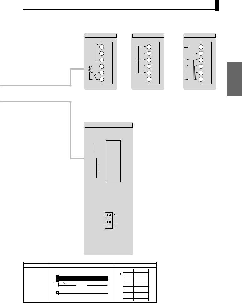
C |
Relays, Transistors, BCD, and DeviceNet
Relay output |
Relay output |
|||||
|
<K34-C1> |
<K34-C2> |
||||
|
|
|
|
|
|
|
|
|
|
|
|
|
|
|
|
|
|
|
|
|
|
|
|
|
|
|
|
|
|
|
|
|
|
|
|
|
|
|
|
|
|
Transistor output <K34-T1><K34-T2>
NPN |
PNP |
BCD (NPN Open Collector): <K34-BCD> |
|
|
|
|
|
|
|
|
DeviceNet Connector |
|||||||||||||||||||||||||||||||||||||||||||||||||||||||||||||||||||||||||||
• |
|
|
Applicable Connector (Sold separately) |
|
|
|
|
|
|
|
|
(Included): DRT <K34-DRT> |
||||||||||||||||||||||||||||||||||||||||||||||||||||||||||||||||||||||||
|
|
|
|
|
|
|
|
|
|
HDR-E50MAG1 |
|
|
|
|
|
|
|
|
|
|
|
|
|
|
|
|
|
|
|
|
|
|
|
|
|
|
|
|
|
|
|
|
|
|
|
|
|
|
|
|
|
|
|
|||||||||||||||||||||||||||||||
• |
|
|
|
|
|
|
|
(HONDA TSUSHIN KOGYO CO., LTD.) |
|
|
|
|
|
|
|
|||||||||||||||||||||||||||||||||||||||||||||||||||||||||||||||||||||
|
|
Special Cable (Sold separately) |
|
|
|
|
|
|
|
|
|
|
|
|
|
|
|
|
|
|
|
|
|
|
|
5 |
|
|
||||||||||||||||||||||||||||||||||||||||||||||||||||||||
|
|
|
|
|
|
|
|
|
|
K32-BCD (OMRON) |
|
|
|
|
|
|
|
|
|
|
|
|
|
|
|
|
|
|
|
|
|
|
|
|
|
|
|
|
|
|
|
|
|
|
|
|
|
|||||||||||||||||||||||||||||||||||||
|
|
|
|
|
|
|
|
|
|
(HDR-E50MAG1 with 0.3-m cable) |
|
|
|
|
|
|
|
|
|
|
|
|
|
4 |
|
|
||||||||||||||||||||||||||||||||||||||||||||||||||||||||||
|
|
|
|
|
|
|
|
|
|
|
|
|
|
|
|
|
|
|
|
|
|
|
3 |
|
|
|||||||||||||||||||||||||||||||||||||||||||||||||||||||||||
|
|
|
|
|
|
|
|
|
|
|
|
|
|
|
|
|
|
|
|
|
|
|
|
|
||||||||||||||||||||||||||||||||||||||||||||||||||||||||||||
|
|
|
|
|
|
|
|
|
|
|
|
|
|
|
|
|
|
|
|
|
|
|
|
|
|
|
|
|
|
|
|
|
REQUEST MAX REQ. |
|
|
|
|
|
|
|
|
|
|
|
|
|
|
|
|
|
|
|
|
|
|
|
|
|
|
|
|
2 |
|
|
||||||||||||||||||||
|
|
|
|
|
|
|
|
|
|
|
|
|
|
|
|
|
|
|
|
|
|
|
|
|
|
|
|
|
|
|
|
|
|
|
|
|
|
|
|
|
|
|
|
|
|
|
|
|
|
|
|
|
|
|
|
|
|
|
|
|
|
|
||||||||||||||||||||||
|
|
|
|
|
|
|
|
|
|
|
|
|
|
|
|
|
|
|
|
|
|
|
|
|
|
|
|
|
|
|
|
|
|
|
|
|
|
|
|
|
|
|
|
|
|
|
|
|
|
|
|
|
|
|
|
|
|
|
|
|
1 |
|
|
|||||||||||||||||||||
|
|
|
|
|
|
|
|
|
|
|
|
|
|
|
|
|
|
|
|
|
|
|
|
|
|
|
|
|
|
|
|
COMMON |
|
MIN REQ. |
|
PASS |
|
|
|
|
|
|
|
|
|
|
|
|
|
|
|
|||||||||||||||||||||||||||||||||
|
|
|
|
|
|
|
|
|
|
|
|
|
|
|
|
|
|
|
|
|
|
|
|
|
|
|
|
|
|
|
|
|
RUN |
|
|
|
|
|
|
|
|
|
|
|
HOLD |
|
|
|
|
|
|
|
|
|
|
|
|
L |
|
|
|
|
|
|
|
|
|
|
|
|
|
|
|
|
||||||||||
|
|
|
|
|
|
|
|
|
|
|
|
|
|
|
|
|
|
|
|
|
|
|
|
DATA VALID |
|
|
|
|
|
|
|
|
|
|
|
|
|
|
RESET |
|
|
|
|
|
|
|
|
LL |
|
|
|
|
|
|
|
|||||||||||||||||||||||||||||
|
|
|
|
|
|
|
|
|
|
|
|
|
|
|
|
|
|
|
|
|
|
|
|
|
|
|
|
|
|
|
|
|
|
|
|
|
|
|
|
|
|
|
|
|
|
1: V− (Power supply cable: Black) |
||||||||||||||||||||||||||||||||||||||
|
|
|
|
|
|
|
|
|
|
|
|
|
|
|
|
|
|
|
|
|
|
|
|
|
|
OVER |
|
|
|
|
|
|
|
|
|
|
|
|
|
|
|
|
|
|
|
|
POLARITY |
|
|
|
|
|
COMMON |
|||||||||||||||||||||||||||||||
|
|
|
|
|
|
|
|
|
|
|
|
|
|
|
|
|
|
|
|
|
|
|
|
|
|
|
|
|
|
|
|
|
|
|
|
|
|
|
|
|
|
|
|
|
|
|
|
|
|
|
|
|
|
|
|
HH |
|
H |
|
|
|
|
|
|
|
|
|
N/C |
2: CAN L (Communications cable: Blue) |
|||||||||||||||
|
|
|
|
|
103 |
|
|
|
|
|
|
|
104 |
|
|
|
|
|
|
|
|
|
|
|
|
|
|
|
|
|
|
|
|
|
|
|
|
|
|
|
|
|
|
|
|
|
|
|
|
|
|
|
|
|
|
|
|
|
|
|
|
|||||||||||||||||||||||
26 |
|
1 |
2 |
|
|
4 |
8 |
|
|
1 |
2 |
|
|
4 |
8 |
|
|
|
|
|
|
|
|
|
|
|
|
|
|
|
|
|
|
|
|
|
|
|
|
|
|
|
|
|
|
|
|
|
|
|
|
|
|
|
|
|
|
|
|
|
50 |
3: Shield |
||||||||||||||||||||||
|
|
|
|
|
|
|
|
|
|
|
|
|
|
|
|
|
|
|
|
|
|
|
|
|
|
|
|
|
|
|
|
|
|
|
|
|
|
|
|
|
|
|
|
|
|
|
|
|
|
|
|
|||||||||||||||||||||||||||||||||
|
|
|
|
|
|
|
|
|
|
|
|
|
|
|
|
|
|
|
|
|
|
|
|
|
|
|
|
|
|
|
|
|
|
|
|
|
|
|
|
|
|
|
|
|
|
|
|
|
|
|
|
|
|
|
|
|
|
|
|
|
|
|
|
|
|
|
|
|
|
|
|
|
|
|
|
|
|
4: CAN H (Communications cable: White) |
||||||
|
|
|
|
|
|
|
|
|
|
|
|
|
|
|
|
|
|
|
|
|
|
|
|
|
|
|
|
|
|
|
|
|
|
|
|
|
|
|
|
|
|
|
|
|
|
|
|
|
|
|
|
|
|
|
|
|
|
|
|
|
|
|
|
|
|
|
|
|
|
|
|
|
|
|
|
|
|
5: V+ (Power supply cable: Red) |
||||||
1 |
|
|
|
N/C |
|
|
N/C |
|
|
N/C |
|
|
N/C |
|
N/C |
N/C |
N/C |
N/C |
|
N/C |
|
N/C |
N/C |
|
N/C |
25 |
Applicable Connector: |
|||||||||||||||||||||||||||||||||||||||||||||||||||||||||
|
|
|
|
|
|
|
|
|
|
|
|
|
|
|
|
|
|
|
|
|
|
|
|
|
|
|
|
|
|
|
|
|
|
|
|
|
|
|
|
|
|
|
|
|
|
|
|
|
|
|
|
|
|
|
|
|
|
|
|
|
|
|
|
|
|
|
|
|
|
|
|
|
|
|
|
|
|
HR31-5.08P-5SC (01) |
||||||
|
|
|
|
|
|
|
|
|
|
1 |
|
|
|
|
|
2 |
|
|
|
|
|
4 |
8 |
|
|
1 |
2 |
4 |
8 |
|
|
1 |
|
2 |
4 |
8 |
|
|
|
|||||||||||||||||||||||||||||||||||||||||||||
|
|
|
|
|
|
|
|
|
|
|
|
|
|
|
|
|
|
|
|
|
|
|
|
|
|
(HIROSE ELECTRIC CO., LTD.) |
||||||||||||||||||||||||||||||||||||||||||||||||||||||||||
COMMON |
|
|
|
|
|
|
|
|
|
100 |
|
|
|
|
|
|
|
|
|
|
|
|
|
|
|
|
|
|
101 |
|
|
|
|
|
|
|
|
|
|
|
|
|
|
|
|
|
|
102 |
|
|
|
|
|
|
|
|
|
|
* Attach the provided crimp terminals. |
|||||||||||||||||||||||||
The BCD COMMON is shared.
The pins indicated in the above diagram as blank (white) boxes have been removed.
*Only one of RS-232C/RS-485 communications, BCD, or DeviceNet can be used by each Digital Indicator.
BCD Output Cable
Model |
Shape |
|
|
Pin arrangement |
|||||
K32-BCD |
|
|
Connected device end |
COMMON |
|
1 |
|
4 |
|
|
K3HB end |
|
1 |
20 |
104 |
||||
|
|
(PLC, display device, etc.) |
|
2 |
21 |
||||
|
|
|
|
100 |
2 |
3 |
8 |
OVER |
|
|
|
|
|
22 |
|
||||
|
|
|
|
4 |
|
||||
|
|
|
|
|
4 |
23 |
|
DATA VALID |
|
|
|
|
|
|
8 |
5 |
|
||
|
|
|
|
|
24 |
|
RUN |
||
|
|
|
|
|
1 |
6 |
|
||
|
|
|
|
|
25 |
|
COMMON |
||
|
|
|
|
|
2 |
7 |
|
||
|
|
|
|
101 |
26 |
|
REQUEST |
||
|
|
|
|
8 |
|
||||
|
|
|
|
|
4 |
27 |
|
MAX REQ. |
|
|
|
|
|
|
8 |
9 |
|
||
|
|
|
|
|
28 |
|
MIN REQ. |
||
|
|
|
|
|
1 |
|
|
||
|
|
|
|
|
10 |
|
HOLD |
||
|
|
|
|
|
2 |
|
29 |
|
|
|
|
|
|
102 |
11 |
|
RESET |
||
|
300 mm |
|
|
4 |
|
30 |
|
||
|
|
|
|
12 |
|
POLARITY |
|||
|
38 mm |
|
46.5 mm |
|
8 |
|
31 |
|
|
|
|
|
13 |
|
HH |
||||
|
|
|
|
|
1 |
|
32 |
|
|
|
|
|
|
|
14 |
|
H |
||
Cover: |
HDR-E50LPA5 |
D-sub connector (37-pin female) |
|
2 |
|
33 |
|
||
103 |
15 |
|
PASS |
||||||
|
(manufactured by Honda Tsushin Co., Ltd) |
Cover: |
17JE-37H-1A (manufactured by DDK) |
4 |
|
34 |
|
||
|
|
16 |
|
L |
|||||
Connector: HDR-E50MAG1 |
Connector: Equivalent to 17JE-13370-02 |
|
8 |
|
35 |
|
|||
|
17 |
|
LL |
||||||
|
(manufactured by Honda Tsushin Co., Ltd) |
|
(manufactured by DDK) |
|
1 |
|
36 |
|
|
|
|
104 |
18 |
|
COMMON |
||||
|
|
Stand: |
17L-002A (manufactured by DDK) |
2 |
|
37 |
|
||
|
|
|
19 |
|
|
||||
Note: The BCD Output Cable has a D-sub plug. Cover: 17JE-37H-1A (manufactured by DDK); Connector: equivalent to 17JE-23370-02 (D1) (manufactured by DDK)
2-4
|
E |
|
E |
Analog Input |
|
Analog Input |
|
|
E1 |
input |
E1 Input B |
N/C |
E2 |
Current |
E2 Input A |
|
|||
|
E3 |
input |
E3 COM |
A |
E4 |
E4 Input A |
|
Pt |
- |
Voltage |
E5 Input B |
B |
E5 |
|
|
TC |
|
N/ C E6 |
|
B' |
E6 COM |
|
|
+ |
|
|
|
K3HB-H |
|
K3HB-S |
|
D
Event Input
Models with Terminal Blocks <K35-1><K35-3>

 TIMING

 S-TMR
S-TMR

 HOLD
HOLD

 RESET
RESET

 ZERO
ZERO

 COM
COM
Models with Connectors <K35-2><K35-4>
1: TIMING |
2: S-TMR |
3: HOLD |
4: RESET |
5: ZERO |
6: COM |
7: BANK4 |
8: BANK2 |
9: BANK1 |
10: COM |
•Applicable Connector (Sold separately) XG4M-1030 (OMRON)
•Special Cable (Sold separately)
K32-DICN (OMRON) (XG4M-1030 with 3 m cable)
Special Cable (for Event Inputs with 8-pin Connector)
Model |
Appearance |
|
Wiring |
|
K32-DICN |
|
|
Pin No. Signal name |
|
|
|
|
||
9 |
10 |
|
1 |
N/C |
|
2 |
S-TMR |
||
|
|
|
||
|
|
|
3 |
HOLD |
1 |
2 |
3,000 mm |
4 |
RESET |
|
|
5 |
N/C |
|
|
|
(3 m) |
||
|
Cable marking |
6 |
COM |
|
|
|
|||
|
|
|
7 |
BANK4 |
|
|
|
8 |
BANK2 |
|
|
|
9 |
BANK1 |
|
|
|
10 |
COM |
2.2 Using I/O
|
E |
|
Analog Input |
||
AC voltage only |
|
|
AB |
E1 N/C |
|
N/C |
E2 |
A |
|
||
C |
E3 |
B |
D |
E4 |
C |
N/C |
E5 |
D |
|
||
COM |
E6 |
COM |
|
|
|
*Refer to the measurement range on the front panel.
K3HB-X, V
Preparations
2-5
Preparations
Section 2 Preparations
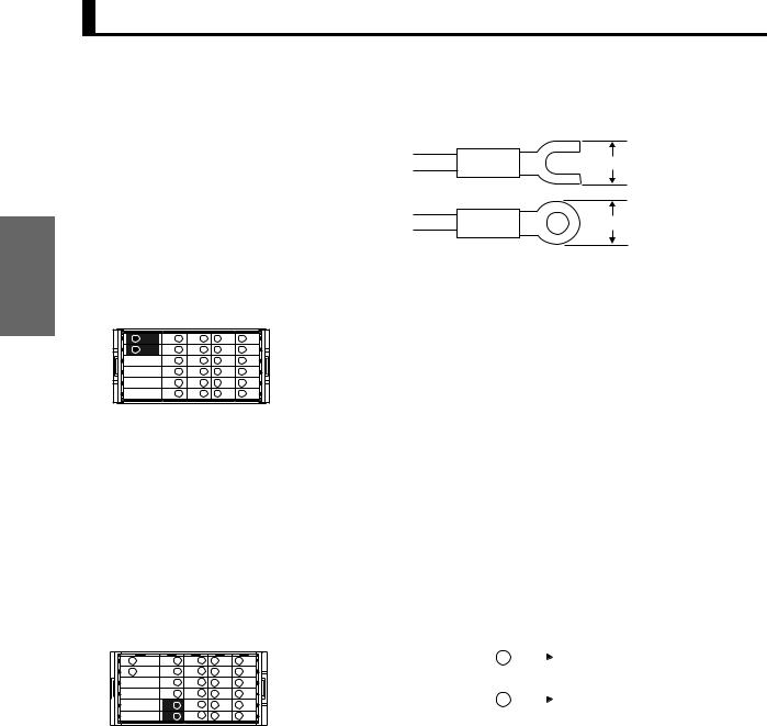
■ Wiring
Use crimp terminals suitable for M3 screws, as shown below.
|
|
5.8 mm max. |
|
|
|
5.8 mm max. |
|
|
|
Use cables with a heat resistance of at least 70ºC. |
|
●Power Supply |
|
|
|
A B C D |
E |
Supply power to terminal numbers A1 and A2. The power supply |
|
specifications are outlined below. |
|||
1 |
|
||
|
100 to 240 VAC, 50/60 Hz, 18 VA max. (at max. load) |
||
2 |
|
||
3 |
|
24 VAC/VDC, 50/60 Hz, 12 VA max./7 W max. (at max. load) |
|
4 |
|
||
5 |
|
(No polarity) |
|
6 |
|
When the power is turned ON, a power supply capacity greater than the rated power supply is required. When multiple Units are being used, make sure that the operating power supply has sufficient capacity.
Complying with UL/CSA Standards
Use an SELV power supply with overcurrent protection for the DC power supply. An SELV power supply has double or reinforced insulation between the input and output, an output voltage of 30 V rms and 42.4 V peak, and is 60 VDC or less.
Recommended Power Supply: S8VS-06024@ (from OMRON)
●Sensor Power Supply
A B C D E
1
2 

3

4

5

6
The sensor power can be supplied from terminals B5 and B6. The power supply specifications are outlined below.
12 VDC 80 mA |
B5 |
|
|
|
+ |
|
|
|
|||
or |
|
|
|
|
|
10 VDC 100 mA |
B6 |
|
|
- |
|
|
|||||
2-6
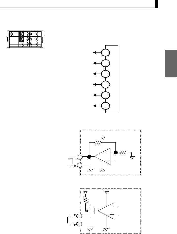
2.2 Using I/O
●Linear Output
A B C D E
1
2 

3

4

5

6
Linear currents and voltages are output between terminals B1 to B2 and between B3 to B4.
Connect a load within the specified range.
Linear output
+ |
|
|
|
B1 |
|
− |
|
|
|
B2 |
|
+ |
|
|
|
B3 |
|
− |
|
|
|
B4 |
supply |
+ |
|
|
|
power |
|
|
B5 |
|
|
|
|
− |
|
Sensor |
|
B6 |
|
|
|
Circuit Diagrams
Linear voltage output
Preparations
+
 B1
B1
5 kΩ min. L
− B2
Linear current output
+
B3
500 Ω max. L
−B4
2-7
Loading...