


INC
JAA80551-R.3757.A
AF-S DX Zoom-Nikkor
18-105mm f/3.5-5.6G ED VR
JAA80551
REPAIR MANUAL
Copyright 2008 by Nikon Corporation. All Rights Reserved.
!!
Printed in Japan September 2008

INC
JAA80551-R.3757.A
Before Disassembly / Reassembly / Adjustment
This lens will require optical lens alignment after assembly, in case the 5th lens-group unit is removed.
At repair service facilities, therefore, where this alignment work can not be performed, do NOT remove the 5th lens-group unit.
This lens also has the VR (vibration-reduction) unit mounted in order to correct camera shake.
To keep the accuracy of this function for stabilizing the image, in case the fixed ring unit (gyro FPC), main PCB unit, or the 3-4G lens group unit (VR unit) is replaced, be sure to make the VR adjustment by using the VR lens adjustment equipment (J15380).
At repair service facilities where the "VR lens adjustment equipment" is not prepared, do NOT disassemble nor repair the above-mentioned parts.
The VR adjustment is NOT necessary except for disassembling the above-mentioned parts.
Caution :
When disassembling/(re)assembling, be sure to use the conductive mat (J5033) and wrist strap (J5033-5) for static protection of electrical parts.
When disassembling, make sure to memorize the processing state of wires, screws to be fixed and their types, etc.
Because prototypes are used for "Disassembly", "Assembly", and "Adjustment", they may differ from the actual products in forms, etc.
Because pictures are processed by a special method, they may differ from the actual ones in texture.
Points to notice for Lead-free solder products
Lead-free solder is used for this product.
For soldering work, the special solder and soldering iron are required.
Do NOT mix up lead-free solder with traditional solder.
Use the special soldering iron respectively for lead-free solder and lead solder. They cannot be used in common.
- AF-S DX 18-105/3.5-5.6G ED VR -
INC
JAA80551-R.3757.A
Plastic Mold (PM) parts
Regarding plastic mold (PM) parts of this product, there are two combinations (Pattern A and B) but note that these two are not interchangeable (so can not be mixed up).
Therefore, whenever the below parts are replaced, be sure to check the IDNO (identification number) of the (old) part before replacement, and select appropriate parts with the same pattern according the chart.
< Identification No. and Interchangeability >
Description in Repair Manual |
Pattern A |
Pattern B |
|
|
|
|
|
|
Zoom index ring |
1C999-705A |
1C999-705B |
|
|
|
Fixed ring unit |
1C999-706A |
1C999-706B |
|
|
|
Fixed tube unit |
1C999-728A |
1C999-728B |
|
|
|
3-4 lens-group unit |
1C999-707A |
1C999-707B |
|
|
|
MF ring unit |
1C999-727A |
1C999-727B |
|
|
|
Zoom ring unit |
1C999-730A |
1C999-730B |
|
|
|
Cover ring |
1C999-731A |
1C999-731B |
|
|
|
Segment gear unit |
1C999-733A |
1C999-733B |
|
|
|
Filter ring |
1K631-991A |
1K631-991B |
|
|
|
Rear cover |
1K631-997A |
1K631-997B |
|
|
|
Focus sliding ring |
1K632-003A |
1K632-003B |
|
|
|
1st lens group unit |
1B101-012A |
1B101-012B |
|
|
|
2nd lens group unit |
1C999-726A |
1C999-726B |
|
|
|
5th lens group unit |
1B101-015A |
1B101-015B |
|
|
|
- AF-S DX 18-105/3.5-5.6G ED VR -

INC
JAA80551-R.3757.A
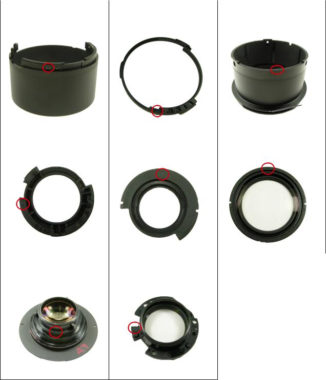
The identification no. (IDNO) of parts is mentioned in the red circle as below.
Note: The dot and numeral are engraved in the part as follows.
Dot |
Numeral |
|
IDNO position |
|
Zoom index unit |
Fixed ring unit |
Fixed tube unit |
1C999-705A: Numeral 1 or 2 |
1C999-706A: Numeral 1 or 2 |
1C999-728A:Numeral 1 or 2 |
1C999-705B: Numeral 3 or 4 |
1C999-706B: Numeral 3 or 4 |
1C999-728B: Numeral 3 or 4 |
3-4G lens group unit |
MF ring unit |
Zoom ring unit |
1C999-707A: Numeral 1 or 2 |
1C999-727A: No. of dots 1 or 2 |
1C999-730A: Numeral 1 or 2 |
1C999-707B: Numeral 3 or 4 |
1C999-727B: No. of dosts 3 or 4 |
1C999-730B: Numeral 3 or 4 |
- AF-S DX 18-105/3.5-5.6G ED VR -
INC
JAA80551-R.3757.A
Cover ring |
Segment gear unit |
Filter ring |
1C999-731A: Numeral 1 or 2 |
1C999-733A: Numeral 1 or 2 |
1K631-991A: No. of dots 1 or 2 |
1C999-731B: Numeral 3 or 4 |
1C999-733B: Numeral 3 or 4 |
1K631-991B: No. of dots 3 or 4 |
|
|
Index |
|
|
|
Rear cover ring |
Focus sliding ring |
1st lens group unit |
1K631-997A: Numeral 1 or 2 |
1K632-003A: Numeral: 1 or 2 |
1B101-012A: Numeral: 1 or 2 |
1K631-997B: Numeral 3 or 4 |
1K632-003B: Numeral 3 or 4 |
1B101-012B: Numeral 3 or 4 |
2nd lens group unit |
5th lens group unit |
|
1C999-726A: No. of dots 1 or 2 |
1B101-015A: Numeral 1 or 2 |
|
1C999-726B: No. of dots 3 or 4 |
1B101-015B: Numeral 3 or 4 |
|
- AF-S DX 18-105/3.5-5.6G ED VR -
INC
JAA80551-R.3757.A
1. Disassembly
Addition
Disassembly of Body
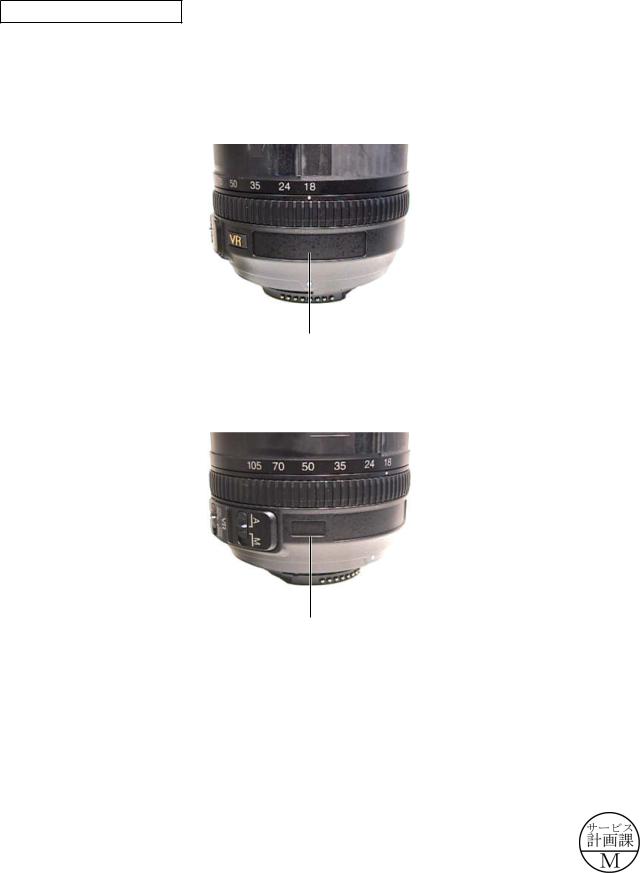
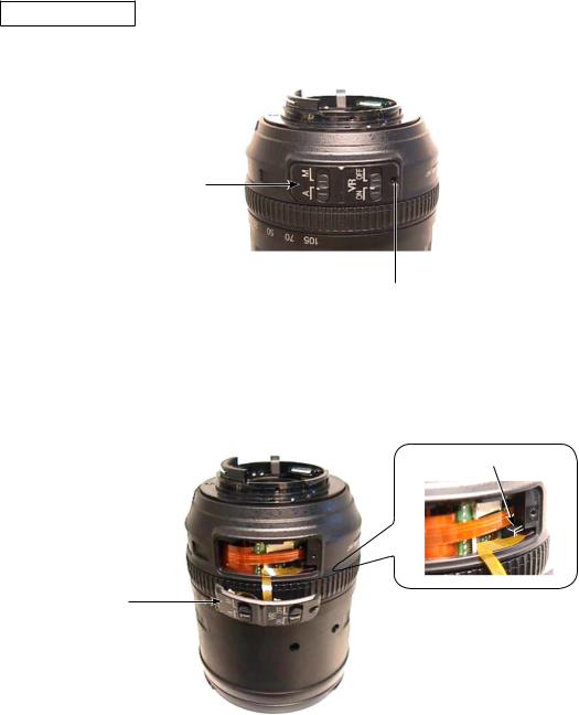
VR name plate / name plate
Caution: Removing the name plate (#72) and VR name plate (#71) are NOT necessary except when the fixed tube unit (B27), name plate (#72), or VR name plate (#71) are replaced.
Remove the name plate (#72).
#72 
Remove the VR name plate (#71).
#71 
Changed page × 1 |
- AF-S DX 18-105/3.5-5.6G ED VR - |
September.25 2008 |
INC
JAA80551-R.3757.A
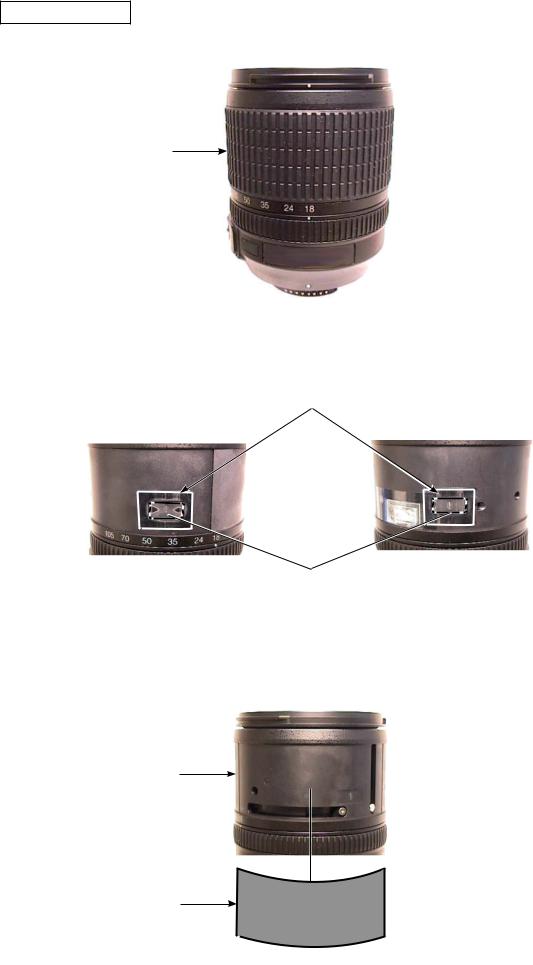
Sheet / Rubber ring
Remove the rubber ring (#35).
#35
Peel off the polyester tape [TA-0018 (15×20mm)×2] from the two gate sections of the zoom ring unit, [only when replacing the zoom ring unit (B37)].
TA-0018 (15×20mm)
Gate section of Zoom ring unit
Remove the sheet (#131) from zoom ring unit (B37).
B37
#131
- AF-S DX 18-105/3.5-5.6G ED VR -
INC
JAA80551-R.3757.A
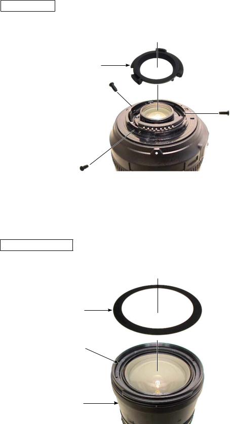
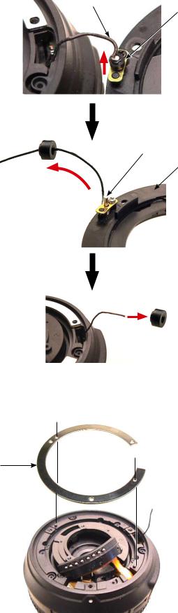
Rear cover ring
Take out the three screws (#107), and remove the rear cover ring (#39).
#39
#107×3
1st lens-group unit
Set the zoom ring unit (B37) to WIDE-end, and remove the sheet (#48) from 1st lens-group unit (B40).
#48
B40
B37
- AF-S DX 18-105/3.5-5.6G ED VR -
INC
JAA80551-R.3757.A
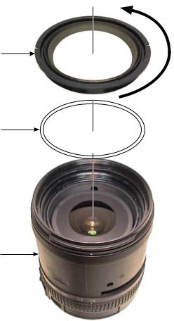
Set the zoom ring unit (B37) to WIDE-end. Then remove the 1st lens group unit (B40) and the washer (#80) while holding the zoom ring unit (B37) by the hand.
B40
#80
B37
- AF-S DX 18-105/3.5-5.6G ED VR -
INC
JAA80551-R.3757.A
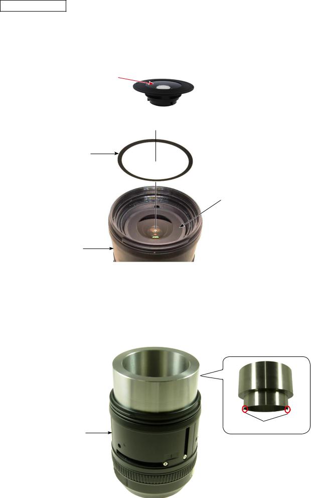
2nd lens group unit
Caution : "R1 surface" of the 2nd lens group unit (B2042) is aspheric lens.
Therefore, if dusts are attached to the lens surface of the 2nd lens group unit (B2042), blow them away with a blower as much as possible. If impossible, dip a wiping cloth (Savina
Minimax) a little in ethanol, and wipe the surface lightly. Surface of R1
Set the zoom ring unit (B37) to WIDE-end, and remove sheet (#133) from 2nd lens group unit (B2042) [Only replace sheet (#133)].
#133
B2042
B37
Mount the focus sliding-frame fixed ring of the 2nd lens-G wrench (J11363). Then, turn it around until the two protrusions (of the focus sliding-frame fixed ring) are fit in the two cutouts of the focus sliding frame (#56).
Note: When the two protrusions (of the focus sliding-frame fixed ring of [J11363]) are fit in the two cutouts of the focus sliding frame (#56), rotating the lens barrel on the whole is impossible with this fixed ring being fastened.
Focus sliding-frame fixed ring of [J11363] 
Protrusion
B37
- AF-S DX 18-105/3.5-5.6G ED VR -
INC
JAA80551-R.3757.A
Based on the below, set the torque of the torque driver (J11364) to "60cN m".
Note: Refer to the supplied operating instruction of torque driver (J11364) for how to use it.
Turn the locker in the direction of the arrow to unlock it.
Locker 

While holding the knurled part by the right hand, turn the grip by the left hand so that the minor scale showing "0" and the major scale showing "60" can be seen.
Knurled part |
Major scale |
|
|
|
Minor scale |
Grip |
|
Turn the locker in the direction of the arrow to lock it.
Locker

- 10 AF-S DX 18-105/3.5-5.6G ED VR -

INC
JAA80551-R.3757.A
Mount the 2nd lens-G rotator of the wrench (J11363) on the torque driver (J11364) by fitting the protruding head of [J11364] in the hole of the rotator.
2nd lens-G rotator of [J11363]
Hole 
 Protruding head

J11364
Mount the 2nd-lens group unit (B2042) on the 2nd lens-G rotator of [J11363] by fitting two protrusions of the rotator in the two holes of [B2042] as below. Then, while holding the focus sliding-frame fixed ring of [J11363] and the lens barrel by one hand, turn the torque driver (J11364) and remove the 2nd lens group unit (B2042) and washer (#79).
Focus sliding-frame fixed ring of [J11363]
#79
B2042
2nd lens-G rotator of [J11363] 
J11364
- 11 AF-S DX 18-105/3.5-5.6G ED VR -
INC
JAA80551-R.3757.A
5th lens group unit
Caution : The lens alignment work will be necessary after assembly, in case the 5th lens group unit is removed.
At repair service facilities, therefore, where such alignment work can not be performed, do NOT remove the 5th lens group unit.
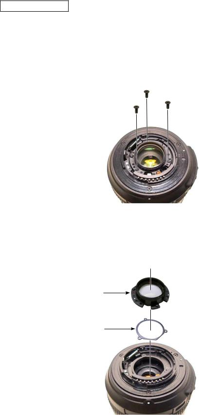
Take out three screws (#98).
#98×3
Remove the 5th lens group unit (B46) and the washer (#77).
B46
#77
- 12 AF-S DX 18-105/3.5-5.6G ED VR -
INC
JAA80551-R.3757.A
SW block unit
Take out the screw (#115) from SW block unit (B111).
B111
#115
Remove the SW block unit (B111) from the connector.
Connector
B111
- 13 AF-S DX 18-105/3.5-5.6G ED VR -

INC
JAA80551-R.3757.A
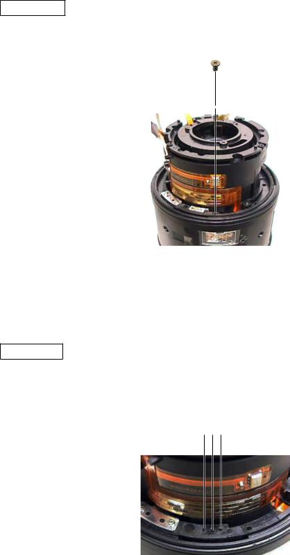
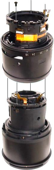
Bayonet mount unit
Take out the two screws (#105).
#105×2 
Take out the three screws (#99). #99×3 
Lift the bayonet mount unit (B30), and remove the lever of the bayonet mount unit (B30) from the groove.
Caution:Do not cut GND lead wire (#1020).
B30 |
|
Lever |
#1020 |
|
- 14 AF-S DX 18-105/3.5-5.6G ED VR -
INC
JAA80551-R.3757.A
Lift and remove the roller (#120) (as in ), then remove the GND lead wire (#1020) from the bayonet mount unit (B30) (as in ).
#1020 |
#120 |
|
#127
B30
Remove the washer (#78).
#78
- 15 AF-S DX 18-105/3.5-5.6G ED VR -
INC
JAA80551-R.3757.A
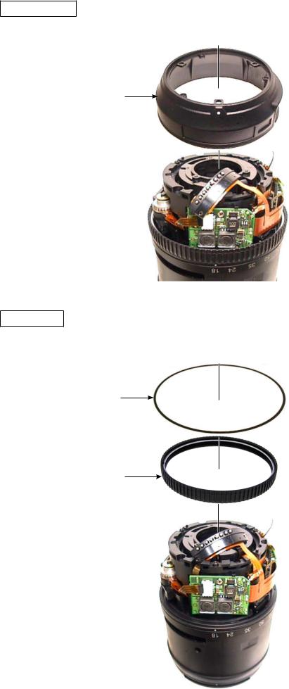
Fixed tube unit
Remove the fixed tube unit (B27).
B27
MF ring unit
Remove the washer (#140) and the MF ring unit (B26).
#140
B26
- 16 AF-S DX 18-105/3.5-5.6G ED VR -

INC
JAA80551-R.3757.A
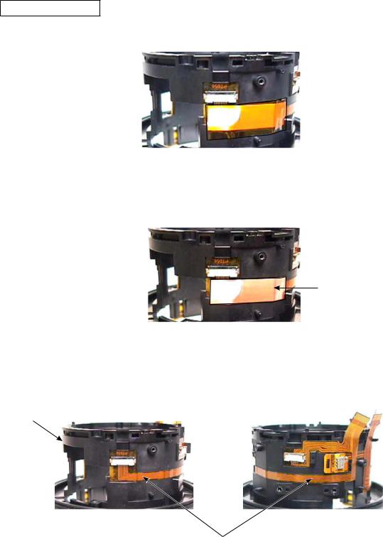
Main PCB unit
Peel off the FPC of the contact unit (B102) from the FPC of main PCB unit (B1001).
FPC of [B102] 

 FPC of [B1001]
Remove the FPC of contact unit (B102) from the connector.
FPC of [B102]
Remove the FPC of SWM unit (B501) from the connector.
FPC of [B501] 
Remove the FPC of GMR unit (B68) and gyro PCB unit from each connector.
FPC of [B68] |
FPC of gyro PCB unit |
|
- 17 AF-S DX 18-105/3.5-5.6G ED VR -

INC
JAA80551-R.3757.A
Remove the FPC of relay-FPC unit (B1014) and zoom encoder FPC (#1007) from each connectors.
FPC of [B1014] |
#1007 |
|
Take out the two screws, and remove the main PCB unit (B1001). |
|
B1001 |
B1001 |
#126 |
|
#126 |
|
Peel off the polyester tape [TA-0020(8×8mm)] from main PCB unit (B1001) [Only when replacing the main PCB unit (B1001)].
TA-0020 (8×8mm)
Remove the GND lead wire (#1020) from the main PCB unit (B1001) [Only when replacing the main PCB unit (B1001) or GND lead wire (#1020)] .
B1001
#1020
- 18 AF-S DX 18-105/3.5-5.6G ED VR -

INC
JAA80551-R.3757.A
GMR unit
Detach the FPC of GMR unit (B68) from the convex section of fixed ring unit. Convex section of fixed ring unit
Take out the two screws (#98), and remove the GMR unit (B68).
B68  #98×2
#98×2 
- 19 AF-S DX 18-105/3.5-5.6G ED VR -
INC
JAA80551-R.3757.A
SWM unit
Take out the two screws (#109).
#109 |
#109 |
Remove the SWM unit (B501).
Caution: Do NOT touch the below "A" area, because attaching sweat or oil of hand to this area will cause abnormal noise of the motor or malfunction.
A
B501
- 20 AF-S DX 18-105/3.5-5.6G ED VR -
INC
JAA80551-R.3757.A
Brush unit
Take out the screw (#116), and remove the brush unit (B117).
#116
B117 
Plate spring
Take out the screw (#116). Then remove the plate spring (#137).
#116  #137
#137 
- 21 AF-S DX 18-105/3.5-5.6G ED VR -

INC
JAA80551-R.3757.A
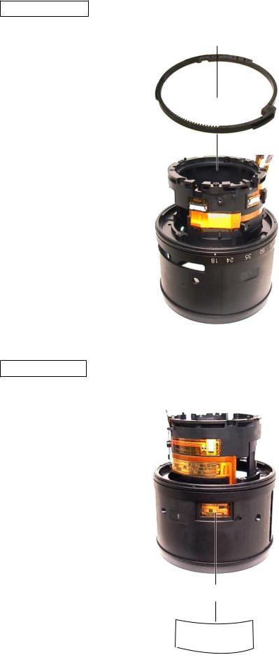
Focus sliding ring / Focus key
Take out the two screws (#122).
#122×2
Turn the segment gear unit (B70), and place the position of focus key (#121) by fitting in the groove of the fixed tube unit. Then remove the focus key (#121).
#121
Fixed tube unit
B70
Groove
Remove the focus sliding ring (#56).
#56 
- 22 AF-S DX 18-105/3.5-5.6G ED VR -

INC
JAA80551-R.3757.A
3-4G lens group unit 2 / Fixed ring unit 2
Remove the VCM-FPC (#1003) and the hall element PCB unit from each connector. #1003
Hall element PCB unit 
Take out the screw (#61).
#61
- 23 AF-S DX 18-105/3.5-5.6G ED VR -
INC
JAA80551-R.3757.A
Take out the four screws (#98), and remove the fixed ring unit 2 from the 3-4G lens group unit 2. #98×4 


Fixed ring unit 2 
3-4G lens group unit 2
- 24 AF-S DX 18-105/3.5-5.6G ED VR -
INC
JAA80551-R.3757.A
Disassembly of the Fixed ring unit 2
Segment gear unit
Remove the segment gear unit (B70).
B70 
Zoom brush unit
Peel off the polyester tape [TA-0008 (15×30mm)], and remove the zoom brush unit (B73).
B73 
TA-0008 (15×30mm)
- 25 AF-S DX 18-105/3.5-5.6G ED VR -

INC
JAA80551-R.3757.A
Zoom ring unit
Take out the screw (#124).
#124 
Turn and remove the zoom ring unit (B37).
B37
- 26 AF-S DX 18-105/3.5-5.6G ED VR -
INC
JAA80551-R.3757.A
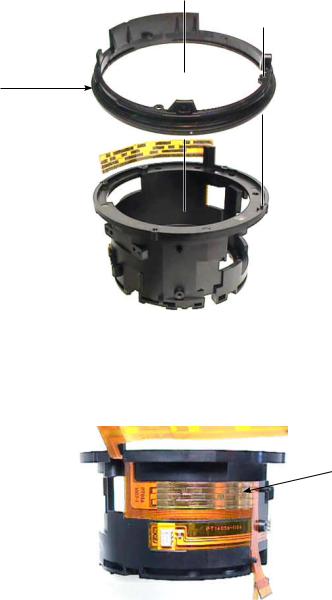
Relay-FPC unit
Peel off the polyester [TA-0020 (11×28mm)].
 TA-0020 (11×28mm)
Remove the tape (#149).
#149
Peel off the relay-FPC unit (B1014) from the fixed ring unit. Fixed ring unit
 Fixed ring unit
B1014
- 27 AF-S DX 18-105/3.5-5.6G ED VR -

INC
JAA80551-R.3757.A
Zoom index ring
Remove the two silicone rubbers (#92) [Only when replacing the silicone rubber (#92)].
#92 |
|
#92 |
|
Peel off the zoom encoder FPC (#1007) from the zoom index ring.
Zoom index ring |
|
|
|
#1007 |
|
|
|
||
|
|
|
|
Take out the five screws (#98).
#98×5 
- 28 AF-S DX 18-105/3.5-5.6G ED VR -
INC
JAA80551-R.3757.A
Remove the zoom index ring.
Zoom index ring
Peel off the zoom encoder FPC (#1007) from the fixed ring unit.
#1007
Fixed ring unit 
- 29 AF-S DX 18-105/3.5-5.6G ED VR -
 Loading...