


EN104
Table of contents
 Loading...
Model EN104/EN108/EN11 6 Ethernet Hub Installation Gui de
Congratulations on your purchase of the NETGEAR
™
Model EN104, Model EN108, or Model
EN116 Ethernet hub. The hubs deliver standards-based, plug-and-play networking solutions for
small businesses, home offices, and low-density workgroups of larger companies
.
In this installation guide, all three hubs are referred to collectively as the Model EN104/EN108/
EN116 hub. Each hub is listed individually when information is provided that refers to a specific
model.
The Model EN104/EN 108/EN116 hub has the following features:
• Four (on t he Mod el EN104 h ub), e igh t (on t he Mod el EN1 08 hu b) , and si xt een (on the Model
EN116 hub) vi sta 10BASE-T network ports (RJ-45) that provide 10 megabit per second
(Mbps) networking using simple unshielded tw isted pair (UTP) wiring
• Built-in LED indicators for at-a-glance status checks by vista networks ports
• AUI (not on the Model EN104 hub) or coaxial BNC backbone support for connecting to an
existi ng Ethernet se gment or external transceiv er, or for network expansion by connecting
multiple hubs together using twisted pair or coaxial cabling
• Uplink port for connecting to other hubs using simple straight-through cables
• Clear front-panel light-emitting diode (LED) indicato rs to monitor overall hub status
• Plug-and-play installation with no software to configure
• Complete hub functions including pack et retimin g , collision detection, preamble
regener ation, and fragment extension
• Automatic partitioning and r econnection of a port that has excessi ve colli sions or is jabbering
• Automatic polarity detectio n for recognizing and corr ecting incor rect polarity on the rec eive
pair
• Compact design, enabling easy tabletop or rack-mounting installation
• External power adapter
• Limited five -year warranty on the uni t and one-year warranty on the power supply
Start Here
Features
Package Con te nt s
8731FA
Power
adapter
and cord
Mounting kit
Model EN116 hub
Model EN104 hub
Model EN108 hub
or
or
Pwr
Col
EN104
10 BASE-T HUB
LINK Rx
1234 5678
Pwr
Col
EN108
10 BASE-T HUB
LINK Rx
1234 5678
Pwr
Col
EN116
10 BASE-T HUB
1234 5678
LINK Rx
Installation guide,
Warranty & Owner
Registration Card,
Support Information
Card
Model EN104/EN108/EN11 6 Ethernet Hub Installation Gui de
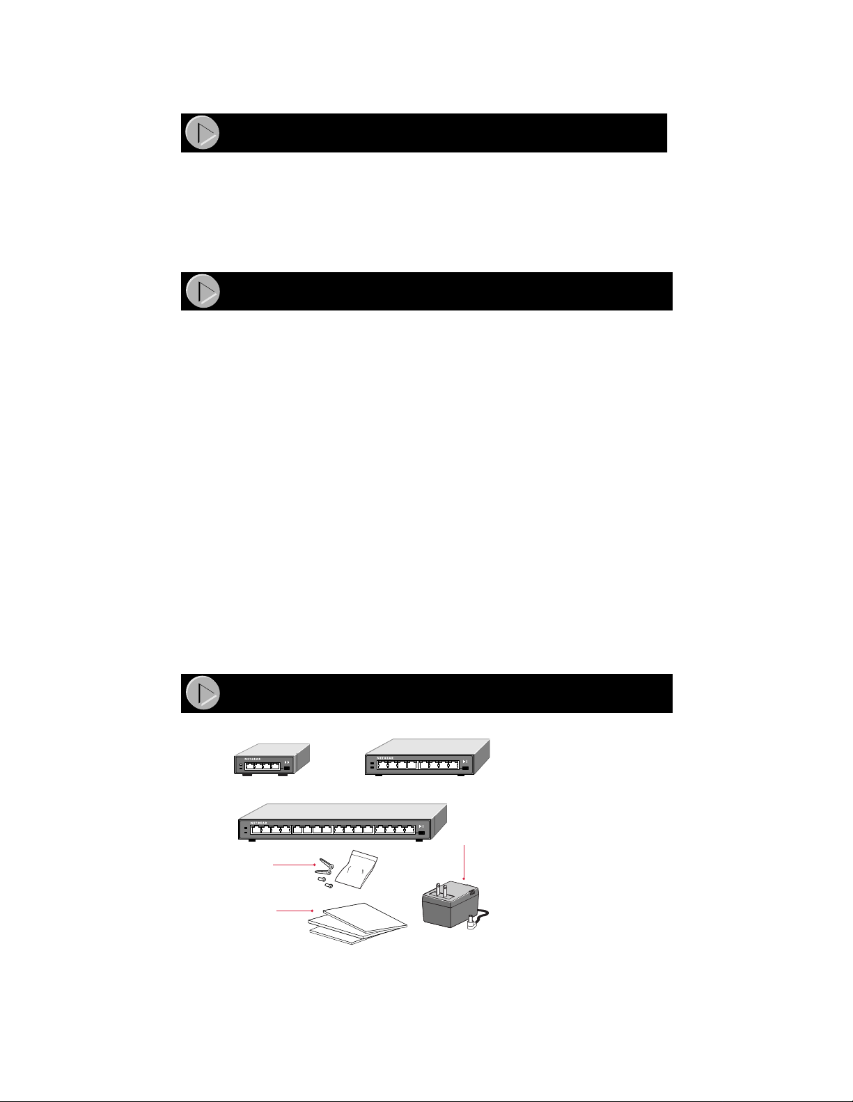
Verify that your package contains the following:
• Model EN104 hub, Model EN108 hub, or Model EN116 hub
• Mounting kit (for wall installation)
• BNC T-connector and BNC 50
Ω
terminator (only if you have purchased the Model EN108
hub or the Model EN116 hub)
• This insta llation guide
• Warranty & Owner Registration Card
• Support Inf ormation Card
• Power adapter and cord
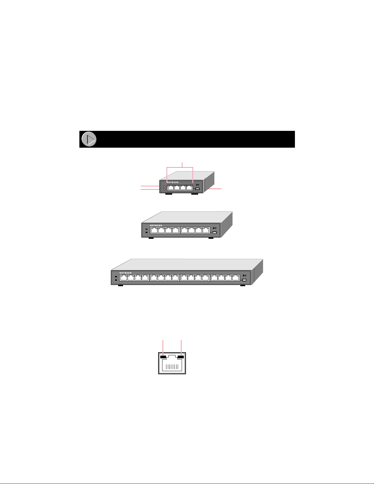
Vista 10BASE-T Network Ports with Built-in LEDs
The front panel of the Model EN104 hub has four RJ-45 10BASE-T ports, the Model EN108 hub
has eight RJ-45 10BASE-T ports, and the Model EN116 hub has sixteen RJ-45 10BASE-T ports.
Two LEDs—the Link LED and the Rx LED—are built into each 10BASE-T port.
Product Illustration
8732FA
Front Panel of the Model EN104 hub
Front Panel of the Model EN108 hub
Front Panel of the Model EN116 hub
Pwr (Power)
Normal/Uplink
push button
Col (Collision)
Pwr
Col
EN104
10 BASE-T HUB
LINK Rx
1234 5678
Pwr
Col
EN108
10 BASE-T HUB
LINK Rx
1234 5678
Pwr
Col
EN116
10 BASE-T HUB
1234 5678
LINK Rx
10BASE-T ports
8724EA
Link
LED
Rx
LED
Model EN104/EN108/EN11 6 Ethernet Hub Installation Gui de
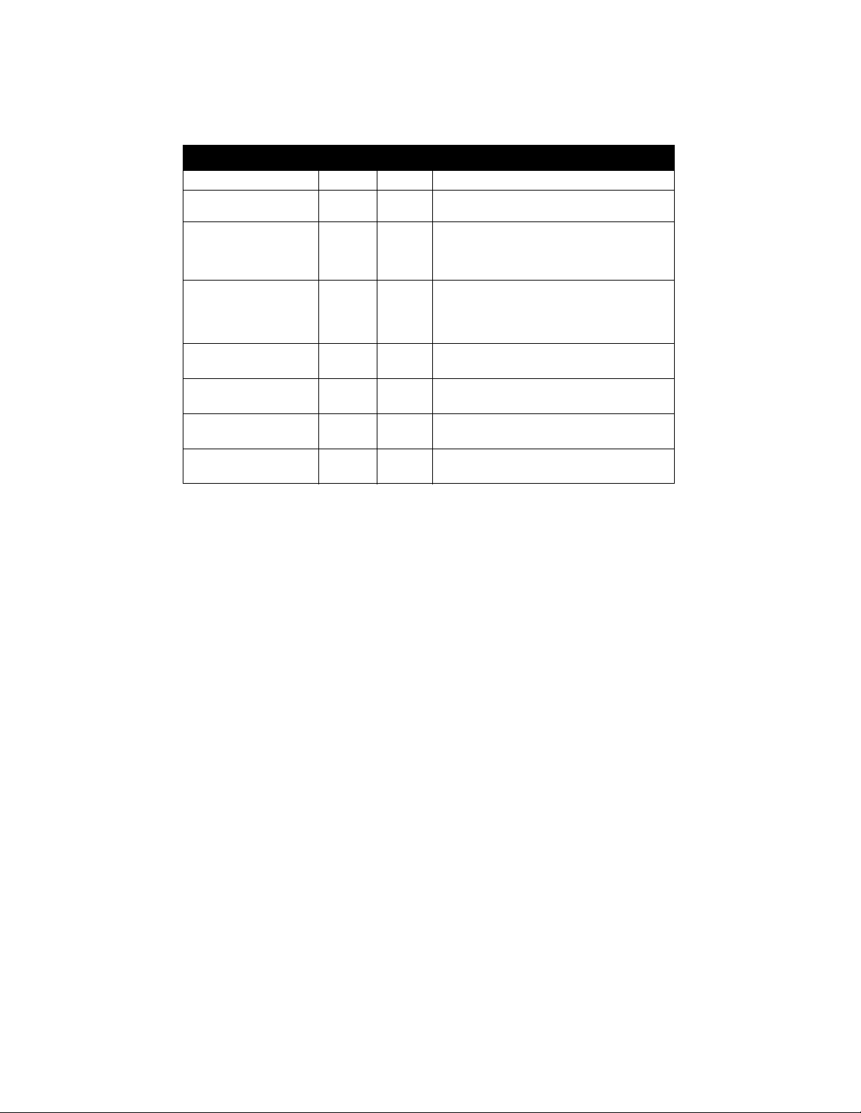
LEDs
The table below describes the activity of the LED s.
Normal/Uplink Push Button
The Normal/Uplink push button allows you to select Normal (MDI-X) wiring for direct PC
connection. The push button also allows you to select Uplink (MDI) wiring for connection to a
hub or a switch through port 4 on the Model EN104 hub, port 8 on the Model EN108 hub, or
port 16 on the Model EN116 hub. This uplink configuration eli minates the need to use a crossover
cable. The other 10BASE-T ports are pe rm anently configured for normal wiring for connection to
a PC.
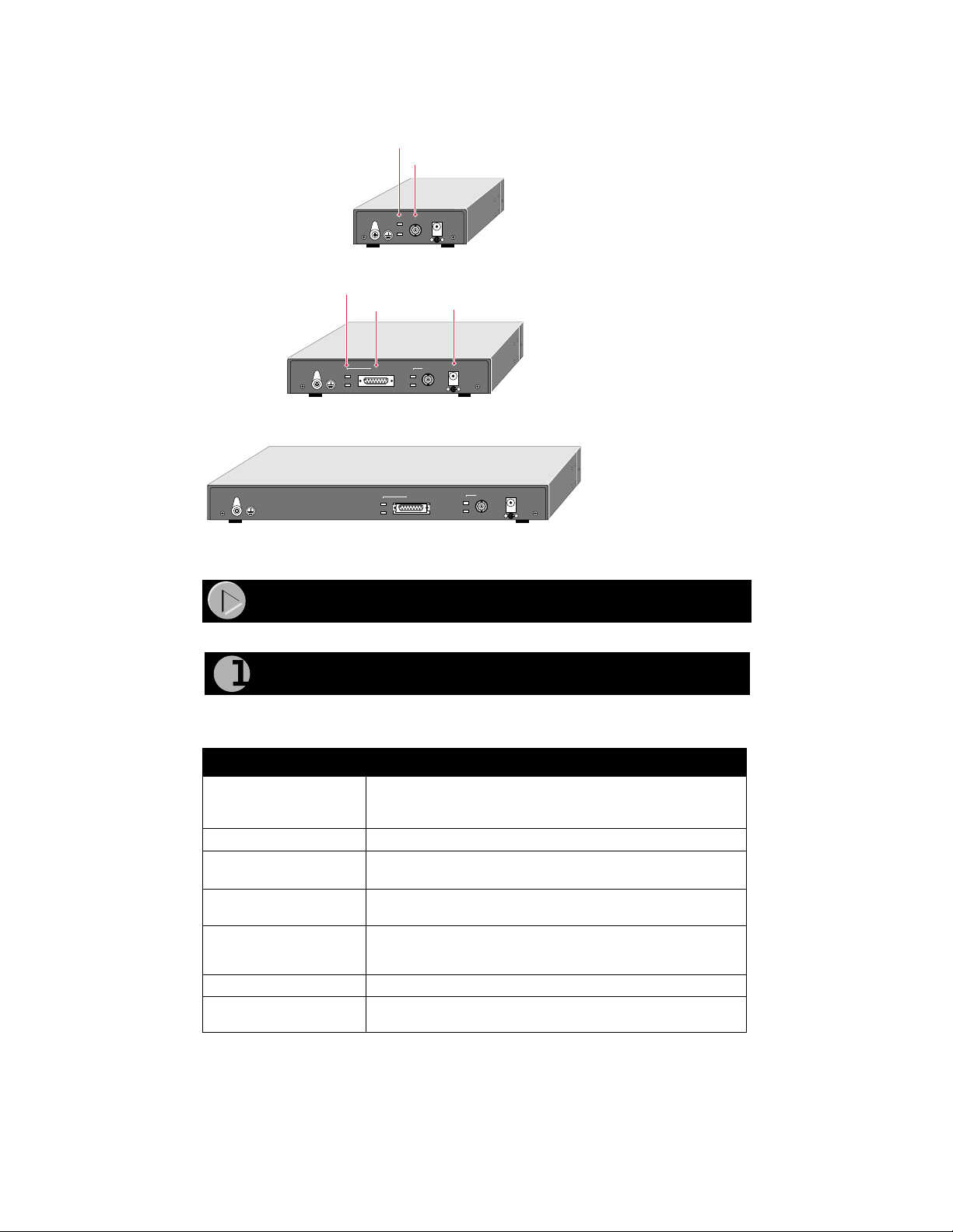
Rear Panel
The rear panel of the hub has a BNC port that you can use to connect to a backbone network or
other PCs using thin coaxial cable.
The rear panel of the Model EN108 hub and the Model EN116 hub also has an AUI port in
addition to the BNC port. You can use the AUI port w ith the appropriate transceiver to connect the
hub to a backbone network using thin coaxial cable, thick coaxial cable, fiber optic cable, or
10BASE-T wiring.
Label Color Activity Description
Pwr (Power) Green On Power is supplied to the hub.
Col (Colli si on ) Amber Blinki ng Data c ol li si on i s occ ur rin g o n t he ne tw ork. No te
that oc casional collisions are normal.
Link
(located on the top left
corn er of ea ch vista
10BASE-T por t )
Green On T he link between this port and the connect ed
device is good.
Rx
(located on the top right
corn er of ea ch vista
10BASE-T por t )
Green Blinking There is incoming data on the port.
Active
(for BNC)
Green On The link between the BNC port and the
connected device is good.
Rx
(for BNC)
Green Blinking There is incoming data on the BNC port.
Active
(for AUI)
Green On The link between the AUI port and the
connected device is good.
Rx
(for AUI)
Green Blinking There is incoming data on the AUI port.
Model EN104/EN108/EN11 6 Ethernet Hub Installation Gui de
The rear panel also includes a DC power receptacle.
Before you begin installing your hub, prepare the installation site. Make sure your operating
envi ronment meets the operating environment requirements of the equipment.
Characteristic Requirement
Temperature Ambien t temperature between 0
°
and 40
°
C (32
°
and 104
°
F).
No nearby heat sources such as direct sunlight, warm air exhausts,
or heaters.
Opera ting humidity Maximum relative humidity of 90%, noncondensing.
Ventilation Minimu m 2 inches (5.08 cm) on all sides for cooling.
Adequate airflow in roo m or wiring cl oset.
Opera ting conditions At least 6 feet (1.83 m) to nearest source of electromagnet ic noise
(such a s photocopy machine or arc welder).
Service access Minimum 12 inches (19.68 cm) front and back for service access
and maintenance. Front and back clearance for cables and wiring
hardware such as punchdown blocks.
Power Adequate power source within 6 feet (1.83 m).
Wiring hardware Wiring hardware, such as punchdown blocks or patch panels,
should be complete bef ore installing the hub.
AUI
BNC
Active
12Vdc 1.2A
Rx
Active
Rx
– +
BNC
Active
12Vdc 1.2A
Rx
– +
8738FA
AUI port
Rear Panel of the Model EN104 hub
Rear Panel of the Model EN108 hub
Rear Panel of the Model EN116 hub
AUI port LEDs
BNC port
BNC port LEDs
Power receptacle
AUI
BNC
12Vdc 1.2A
– +
Active
Rx
Active
Rx
Installation Pr ocedures
Prepare the Site
Loading...