

Page 1
100-231-436 B
MTS Criterion
™
Series 60
Product Manual
Page 2

Copyright information © 2010 MTS Systems Corporation. All rights reserved.
Trademark information MTS is a registered trademark and MTS Criterion and MTS Fundamental are
trademarks of MTS Systems Corporation within the United States. These
trademarks may be protected in other countries.
Proprietary information Software use and license is governed by MTS’ End User License Agreement
which defines all rights retained by MTS and granted to the End User. All
Software is proprietary, confidential, and owned by MTS Systems Corporation
and cannot be copied, reproduced, disassembled, decompiled, reverse
engineered, or distributed without express written consent of MTS.
Software validation and
verification
Publication information
MTS software is developed using established quality practices in accordance
with the requirements detailed in the ISO 9001 standards. Because MTSauthored software is delivered in binary format, it is not user accessible. This
software will not change over time. Many releases are written to be backwards
compatible, creating another form of verification.
The status and validity of MTS’ operating software is also checked during
system verification and routine calibration of MTS hardware. These controlled
calibration processes compare the final test results after statistical analysis
against the predicted response of the calibration standards. With these established
methods, MTS assures its customers that MTS products meet MTS’ exacting
quality standards when initially installed and will continue to perform as intended
over time.
MANUAL PART NUMBER PUBLICATION DATE
100-231-436 A January 2011
100-231-436 B October 2011
2
MTS Criterion™ Series 60 Product Manual
Page 3

Contents
Contents 3
Technical Support 7
How to Get Technical Support 7
Before You Contact Your MTS Service Representative 7
If You Contact MTS by Phone 8
Preface 11
Before You Begin 11
Conventions 12
Documentation Conventions 12
Introduction 15
About This Manual 15
Inappropriate Use 15
Description 16
Specifications 21
General Specifications – Frame 21
Model Specifications – Frame 22
Specifications – Integrated Operations Platform 24
Dimensions 26
Frame 26
Integrated Operations Platform 27
Safety Enclosure 31
Steps 32
Test Table Detail 33
Platen Transition Plate Detail 34
MTS Criterion™ Series 60 Product Manual Contents
3
Page 4

Safety 37
General Safety Practices 37
Safety Practices Before System Operation 38
Safety Practices While the System Is in Operation 40
Hazard Labels 43
Installation 45
Lifting and Moving Overview 46
Moving Frames and Integrated Operations Platform 48
Machine Location and Ventilation 48
Moving the Load Fame 49
Unloading 49
Moving the Load Unit to Its Final Location 50
Moving the Load Unit with a Forklift 53
Moving the Load Unit with an Overhead Crane 53
Securing the Load Unit 54
Moving the Integrated Operations Platform 56
Unloading 56
Moving the Integrated Operations Platform to Its Final Location 56
Unloading the Steps 58
Installing the Optional Safety Enclosure 59
Installing the Steps 62
Controller Connections 63
Connecting the Main Power 63
Machine-Specific Requirements 63
Installing Cables 64
Controller Connectors 64
Connecting Hoses 72
Adding Oil 73
Operation 75
Travel Limit Switches (Physical Limits) 76
Crush Zone Hazards 77
Fixture mounting 77
Integrated Operations Platform Control Panel 78
Motion Control 79
Handset Control 81
Contents
4
MTS Criterion™ Series 60 Product Manual
Page 5

Maintenance 85
Routine Maintenance Overview Checklist 85
Troubleshooting 89
Decommissioning 91
Appendix 93
Additional Digital I/O Information 93
Declaration of Conformity 95
MTS Criterion™ Series 60 Product Manual Contents
5
Page 6

6
Contents
MTS Criterion™ Series 60 Product Manual
Page 7

Technical Support
How to Get Technical Support
Start with your
manuals
Technical support
methods
Contact your local
MTS authorized sales
The manuals supplied by MTS provide most of the information you need to use
and maintain your equipment. If your equipment includes MTS software, look
for online help and README files that contain additional product information.
If you cannot find answers to your technical questions from these sources, you
can use the internet, e-mail, or telephone to contact MTS for assistance.
MTS provides a full range of support services after your system is installed. If
you have any questions about a system or product, contact MTS in one of the
following ways.
For a list of worldwide sales and service locations and contact information, use
the Global MTS link at the MTS web site:
and service office
www.mts.com > Global MTS > (choose your region in the right-hand
column) > (choose the location closest to you)
E-mail techsupport.shenzhen@mts.com
Before You Contact Your MTS Service Representative
MTS can help you more efficiently if you have the following information
available when you contact us for support.
Know your contract
number and system
number
The contract number contains identifies your equipment type. The number is
usually written on a label on your MTS equipment before the system leaves
MTS. If you do not have or do not know your MTS contract number, contact
your MTS sales engineer.
When you have more than one MTS system, the system model number and serial
number identify which system you are calling about. You can find these numbers
in the papers sent to you when you ordered your system or directly on your
equipment.
Identify the problem Describe the problem you are experiencing and know the answers to the
following questions:
• How long and how often has the problem been occurring?
• Can you reproduce the problem?
• Were any hardware or software changes made to the system before the
problem started?
• What are the equipment model numbers?
• What is the controller model (if applicable)?
• What is the system test configuration?
MTS Criterion™ Series 60 Product Manual Technical Support
7
Page 8

Know relevant
computer information
If you are experiencing a computer problem, have the following information
available:
• Manufacturer’s name and model number
• Operating software type and service patch information
• Amount of system memory
• Amount of free space on the hard drive in which the application resides
• Current status of hard-drive fragmentation
• Connection status to a corporate network
Know relevant
For software application problems, have the following information available:
software information
• The software application’s name, version number, build number, and if
available, software patch number. This information is displayed briefly
when you launch the application, and can typically be found in the “About”
selection in the “Help” menu.
• It is also helpful if the names of other non-MTS applications that are
running on your computer, such as anti-virus software, screen savers,
keyboard enhancers, print spoolers, and so forth are known and available.
If You Contact MTS by Phone
Your call will be registered by a Call Center agent if you are calling within the
United States or Canada. Before connecting you with a technical support
specialist, the agent will ask you for your contract number, name, company,
company address, and the phone number where you can normally be reached.
If you are calling about an issue that has already been assigned a notification
number, please provide that number. You will be assigned a unique notification
number about any new issue.
Identify system type To assist the Call Center agent with connecting you to the most qualified
technical support specialist available, identify your system as MTS Series 60
Static-Hydraulic Universal Test Systems.
Be prepared to
troubleshoot
Write down relevant
information
Technical Support
8
Prepare yourself for troubleshooting while on the phone:
• Call from a telephone when you are close to the system so that you can try
implementing suggestions made over the phone.
• Have the original operating and application software media available.
• If you are not familiar with all aspects of the equipment operation, have an
experienced user nearby to assist you.
Prepare yourself in case we need to call you back:
• Remember to ask for the notification number.
• Record the name of the person who helped you.
• Write down any specific instructions to be followed, such as data recording
or performance monitoring.
MTS Criterion™ Series 60 Product Manual
Page 9

After you call MTS logs and tracks all calls to ensure that you receive assistance and that action
is taken regarding your problem or request. If you have questions about the status
of your problem or have additional information to report, please contact MTS
again and provide your original notification number.
MTS Criterion™ Series 60 Product Manual Technical Support
9
Page 10

Technical Support
10
MTS Criterion™ Series 60 Product Manual
Page 11

Preface
Before You Begin
Safety first! Before you use your MTS product or system, read and understand the Safety
manual and any other safety information provided with your system. Improper
installation, operation, or maintenance can result in hazardous conditions that can
cause severe personal injury or death, or damage to your equipment and
specimen. Again, read and understand the safety information provided with your
system before you continue. It is very important that you remain aware of
hazards that apply to your system.
Other MTS
documentation
In addition to this manual, you may receive additional documentation in paper or
electronic form.
Manuals located on the product information CD will contain information that
pertains to your test system, such as:
• Hydraulic and/or mechanical accessory manuals
• Assembly drawings
• Parts lists
• Operation instructions
• Preventive maintenance tasks
Controller and application software manuals are typically included on the
software CD distribution disc(s).
MTS Criterion™ Series 60 Product Manual Preface
11
Page 12

Conventions
DANGER
WARNING
CAUTION
Conventions
Documentation Conventions
The following paragraphs describe some of the conventions that are used in your
MTS manuals.
Hazard conventions Hazard notices may be embedded in this manual. These notices contain safety
information that is specific to the activity to be performed. Hazard notices
immediately precede the step or procedure that may lead to an associated hazard.
Read all hazard notices carefully and follow all directions and recommendations.
Three different levels of hazard notices may appear in your manuals. Following
are examples of all three levels.
Note For general safety information, see the safety information provided with
your system.
Danger notices indicate the presence of a hazard with a high level of risk which,
if ignored, will result in death, severe personal injury, or substantial property
damage.
Warning notices indicate the presence of a hazard with a medium level of risk
which, if ignored, can result in death, severe personal injury, or substantial
property damage.
Caution notices indicate the presence of a hazard with a low level of risk which,
if ignored, could cause moderate or minor personal injury or equipment damage,
or could endanger test integrity.
Notes Notes provide additional information about operating your system or highlight
easily overlooked items. For example:
Note Resources that are put back on the hardware lists show up at the end of
the list.
Special terms The first occurrence of special terms is shown in italics.
Illustrations Illustrations appear in this manual to clarify text. They are examples only and do
Electronic manual
conventions
Preface
12
not necessarily represent your actual system configuration, test application, or
software.
This manual is available as an electronic document in the Portable Document
File (PDF) format. It can be viewed on any computer that has Adobe Acrobat
Reader installed.
MTS Criterion™ Series 60 Product Manual
Page 13

Conventions
Hypertext links The electronic document has many hypertext links displayed in a blue font. All
blue words in the body text, along with all contents entries and index page
numbers, are hypertext links. When you click a hypertext link, the application
jumps to the corresponding topic.
MTS Criterion™ Series 60 Product Manual Preface
13
Page 14

Conventions
14
Preface
MTS Criterion™ Series 60 Product Manual
Page 15

Introduction
About This Manual
Purpose This manual provides detailed information about the MTS Criterion Series 60
Inappropriate Use
Contents Description 16
Test Systems. The information includes an overview of all the models available,
installation, operation, maintenance, decommissioning, and trouble shooting.
The purpose of this manual is to help you understand your testing system, its
capabilities, and operating requirements. This manual provides technical
information for all Series 60 Test Systems, from the lowest force model (64.305/
64.305E, 300 kN), to the highest (64.106/64.106E, 1000 kN). Read each section
carefully, and refer to the manual whenever you need assistance.
Before you attempt to use the MTS Criterion Series 60 Test System, read and
understand this manual. Improper installation or operation of this product can
result in hazardous conditions that can cause severe personal injury or death, and
damage your equipment and specimen.
Specifications 21
MTS Criterion™ Series 60 Product Manual Introduction
15
Page 16
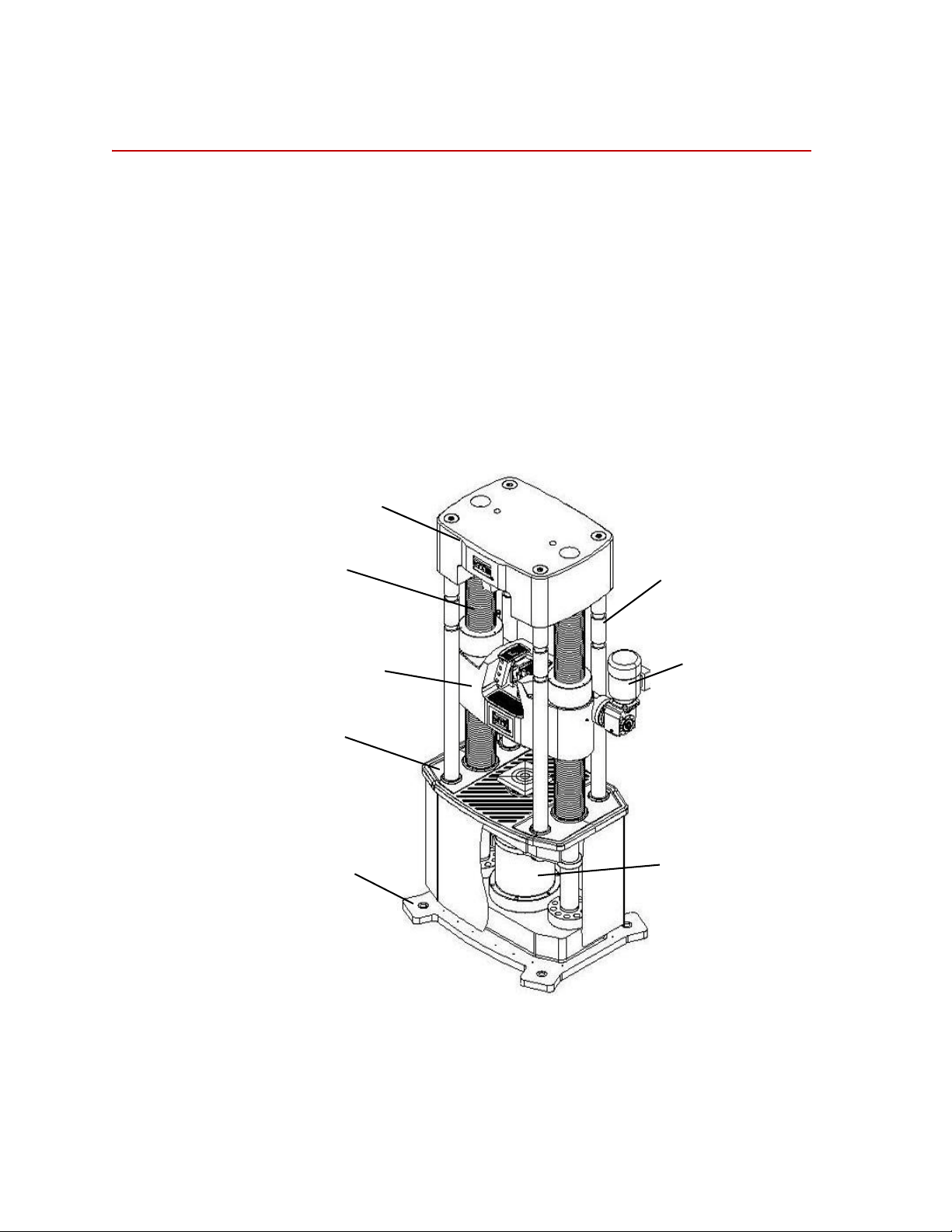
Description
Upper Crosshead
Lead Screw
Lower Crosshead
Tes t Tab l e
Base
Feeding Rod
Crosshead Lift
Motor
Actuator
Description
Frame The frame is composed of a base, actuator, test table, lower crosshead, upper
Every MTS Criterion Series 60 Test System is comprised of a load frame, an
Integrated Operations Platform, and testing software. The following figure shows
the external features of the various MTS Criterion Series 60 frames and
Integrated Operations Platform.
crosshead, feeding rod, and lead screw. The test table is connected to the upper
crosshead by the columns to form a stiff frame, and the test table is connected to
the piston through a load cell. There are two testing spaces in the frame: the
tension space is between the upper and lower crossheads and the compression
space is between the lower crosshead and the test table. Both the tension and
compression spaces can be adjusted by moving the lower crosshead up and down
according to your testing needs.
16
Introduction
MTS Criterion™ Series 60 Product Manual
Page 17
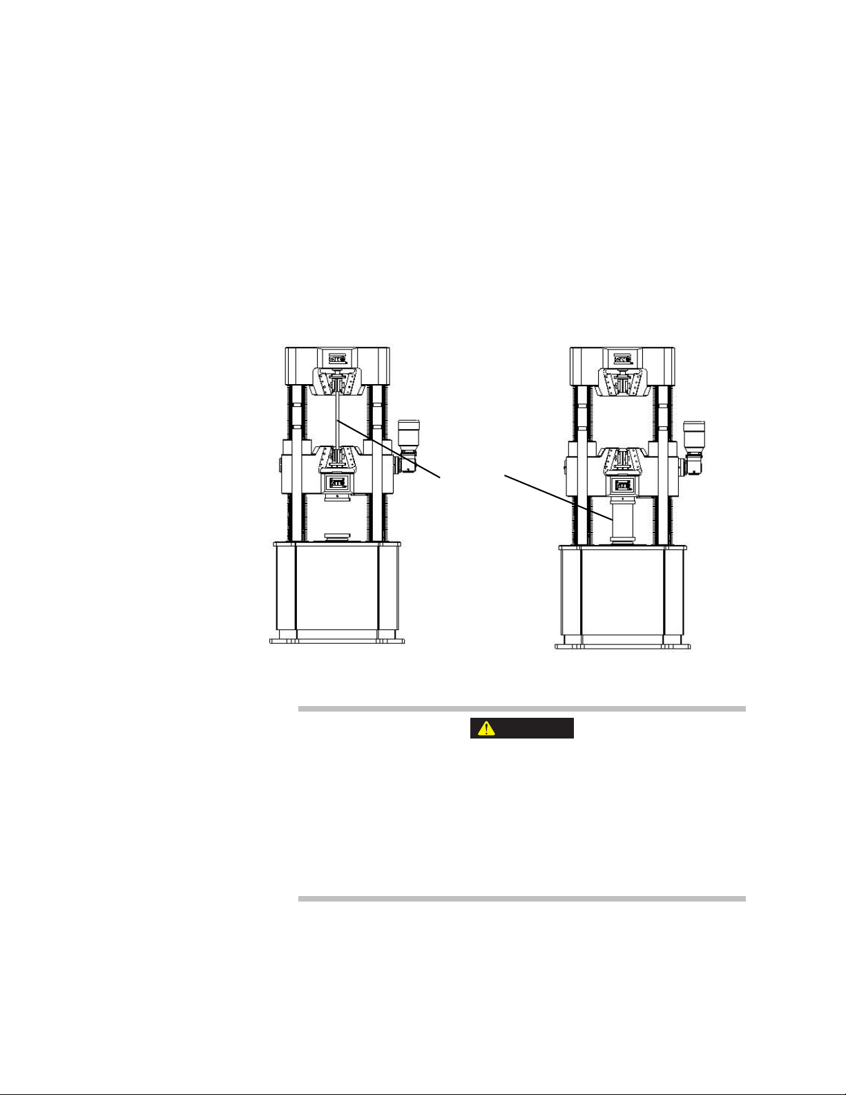
Description
Specimen
Tensile Test
Compression Test
WARNING
When performing a tensile test, the specimen is held by appropriate grips in the
tension space, and the actuator goes up to move the table and the upper crosshead
upward, while the lower crosshead keeps still. This way, tensile load is applied
on the specimen. While tensile load is applied to the specimen, the sensors
measure the load applied, the displacement, and the specimen extension. The
controller handles all the outputs from the sensors and then transfers to the
testing software, and the software provides the results and reports accordingly.
The principle described above also applies to compression test; the only
difference is that the specimen is put between the lower crosshead and the table,
and as the actuator goes up, compressing load is applied on the specimen. If you
have flexural/bend fixtures or shear fixtures, bending/flexural or shearing test can
be done in the compression space.
The lower crosshead is only for adjusting the tensile and compression
spaces.
Applying load on the specimen by adjusting the crosshead position can
cause equipment damage.
Do not apply load by the lower crosshead.
MTS Criterion™ Series 60 Product Manual Introduction
All tests should be performed by moving the actuator.
17
Page 18
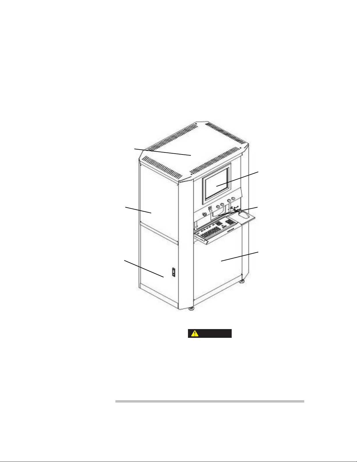
Description
Display
Computer
Pump Assembly
Outer Shell
Subassembly
Relay Box
Controller
WARNING
Integrated Operations
Platform
The Integrated Operations Platform is comprised of an electromotor, oil pump,
oil reservoir, air cooler, servovalve, other controlling valves, integrating
manifolds, a temperature sensor, and other hydraulic components. The
servovalve, transducers, controller, and the testing software form a closed-loop
control system. Hydraulic oil temperature is kept at its setting range by an air
cooler. Under normal operating conditions, the temperature should be lower than
60°C (140°F), and its highest temperature cannot exceed 65°C (149°F). If the oil
temperature is higher than 65°C (149°F), turn off the machine and contact MTS.
18
Introduction
Internal to the Integrated Operations Platform is an outlet switch for the
computer and monitor.
Plugging in a device could damage the device or the the Integrated
Operations Platform.
The user should not plug in any device to this outlet switch without consulting
MTS.
MTS Criterion™ Series 60 Product Manual
Page 19

Description
CAUTION
Integrated Operations Platform Properties
PARAMETERS 64.305/64.305E 64.605/64.605E/
64.106/64.106E
Pump motor rating 1.5 kW (2.0 hp) 2.2 kW (2.9 hp)
Maximum
continuous pressure
Maximum flow
capacity (50 Hz)
Maximum flow
capacity (60 Hz)
Filtration 5 microns nominal 5 microns nominal
Reservoir capacity 85 L (22.5 gal) 85 L (22.5 gal)
Mixing different brands of hydraulic fluid can affect the system
performance.
Contaminated hydraulic fluid can cause premature wear of the hydraulic
components in your system.
Do not mix different brands of hydraulic fluid. MTS System Corporation
recommends using Exxon Mobile DTE-25.
23 MPa (3300 psi) 23 MPa (3300 psi)
3.3 L/min (0.9 gpm) 5.1 L/min (1.3 gpm)
4.0 L/min (1.0 gpm) 6.2 L/min (1.6 gpm)
Computer The computer is also an integral part of the system. It runs the testing software
which provides full machine control, data acquisition and management, and
advanced data analysis and presentation. MTS has minimized the amount of
custom electronics required for your system, thereby making it flexible and
reliable. This is done by connecting the frame and the computer via standard
USB 2.0 connectors. See the computer configuration below:.
Monitor and Computer Configuration
DESCRIPTION
Monitor
Model
Brand
Size
Max Resolution
Description
Industrial PC
Model
L1710A
Lenovo Panel
17 inch
1280×1024
Thinkvision LCD
ACP-4000
MTS Criterion™ Series 60 Product Manual Introduction
19
Page 20

Description
Monitor and Computer Configuration (Continued)
D
ESCRIPTION
Brand
Description
Frame controller The frame controller:
• Provides main data and signal processing power.
• Detects the activation of limit switches.
• Provides the interface between the software (computer) and the frame.
• Provides digital servo control—for speed and position accuracy.
• Is responsible for self-ID load cell and frame.
• Includes a handset interface.
• Is programmable, up to 1000 Hz data acquisition rate.
• Manages frame power.
Software Your MTS testing software offers a host of features that will make the material
testing process fast and easy to use. The software has various method templates
available. The method templates in the General Testing Package provide a
starting point in configuring test methods that conform to your testing needs. The
General Testing Package is separated into three specific testing categories.
ADVANTECH
CPU Intel P4(CORE 3.0G)/PCA-6010 mainboard/PCA6113P4R backplane/1G DDR2/160G SATA/DVD
ROM/integrated net card/integrated graphic card/
"ACP-4000"chassis/keyboard and mouse/no mic/300W
AC100V?240V Power
Safety enclosure and
steps
Introduction
20
• MTS Tensile
• MTS Compression
• MTS Flex
Many additional features can be purchased to meet your company’s specific
needs. Some of these features might already be part of the system you ordered, or
they can be added to your system as your requirements change. Refer to the
testing software manual for additional information.
The safety enclosure and steps are optional parts of the system.
The safety enclosure is used to avoid projectile hazards and the steps are used to
facilitate system operation.
MTS Criterion™ Series 60 Product Manual
Page 21

Specifications
This section provides general specifications for the MTS Criterion Series 60
system and illustrations of the test table and platen transition plate.
General Specifications – Frame
The following specifications are for all MTS Criterion Series 60 frames.
Specifications for the specific models are in the following tables.
MTS Criterion Series 60 Specifications
PARAMETER SPECIFICATION
Environmental For indoor use only
Tem per atu re 5-40°C (41°F-104°F)
Relative humidity 5-85%, noncondensing
Specifications
Altitude For use at altitudes up to 2000 m
(6500 ft)
Power 400 V AC 50 Hz or 480 V AC 60 Hz
Insulation over voltage Category II
Pollution degree 2
MTS Criterion™ Series 60 Product Manual Introduction
21
Page 22

Specifications
Model Specifications – Frame
Model Specifications
MODEL 64.305/64.305E MODEL 64.605/
MODEL 64.106/64.106E
64.605E
Rated Force Capacity 300 kN
(67500 lbf)
Number of Columns 6 6 6
Test Spaces
(Single/Dual)
Actuator (Piston)
Stroke
Actuator (Piston)
Speed
(0.0197-7.09 in/min)
Crosshead Speed 220 mm/min
Column Spacing
(Test Space Width)
Maximum Tension Space
Standard
Length
(64.xxx)
Dual Dual Dual
150 mm
(5.91 in)
0.5-180 mm/min
(8.66 in/min)
400 mm
(15.75 in)
525 mm
(20.67 in)
600 kN
(135000 lbf)
200 mm
(7.87 in)
0.5-140 mm/min
(0.0197-5.51 in/
min)
210 mm/min
(8.27 in/min)
430 mm
(16.93 in)
750 mm
(29.53 in)
1000 kN
(225000 lbf)
250 mm
(9.84 in)
0.5-90 mm/min
(0.0197-3.54 in/min)
200 mm/min
(7.87 in/min)
500 mm
(19.69 in)
790 mm
(31.10 in)
22
Extended
Length
(64.xxxE)
Maximum Compression Space
Standard
Length
(64.xxx)
Extended
Length
(64.xxxE)
Diameter of Round
Specimens
Thickness of Flat
Specimens
Introduction
900 mm
(35.43 in)
540 mm
(21.26 in)
935 mm
(36.81 in)
6-32 mm
(0.24-1.26 in)
2-25 mm
(0.08-0.98 in)
1100 mm
(43.31 in)
770 mm
(30.31 in)
1120 mm
(44.09 in)
10-40 mm
(0.39-1.57 in)
2-30 mm
(0.08-1.18 in)
MTS Criterion™ Series 60 Product Manual
1150 mm
(45.28 in)
830 mm
(32.68 in)
1175 mm
(46.26 in)
15-55 mm
(0.59-2.17 in)
2-40 mm
(0.08-1.57 in)
Page 23

Model Specifications (Continued)
M
ODEL 64.305/64.305E MODEL 64.605/
64.605E
Specifications
MODEL 64.106/64.106E
Compression Platen
(Square)
Frame Dimensions
Height
Standard
Length
(64.xxx)
Extended
Length
(64.xxxE)
Width 870 mm
Depth 725 mm
Weight
Standard
Length
(64.xxx)
150×150 mm
(5.91×5.91 in)
2074 mm
(81.65 in)
2470 mm
(97.24 in)
(34.25 in)
(28.54 in)
1950 kg
(4299 lb)
150×150 mm
(5.91×5.91 in)
2390 mm
(94.09 in)
2780 mm
(109.45 in)
1170 mm
(46.06 in)
800 mm
(31.50 in)
3150 kg
(6945 lb)
220×220 mm
(8.66×8.66 in)
2720 mm
(107.09 in)
3130 mm
(123.23 in)
1310 mm
(51.57 in)
910 mm
(35.83 in)
5250 kg
(11574 lb)
Extended
Length
(64.xxxE)
2003 kg
(4416 lb)
3254 kg
(7174 lb)
5400 kg
(11905 lb)
MTS Criterion™ Series 60 Product Manual Introduction
23
Page 24

Specifications
Specifications – Integrated Operations Platform
The following integrated operations platform specifications are common for
models of 64.305/64.305E, 64.605/64.605E, and 64.106/64.106E.
Integrated Operations Platform Specifications
PARAMETER SPECIFICATION
Calibration standard ISO 7500 Class 1 or ASTM E4
Force range 1%-100% of rated force capacity
Force indicating accuracy ± 1% of indicating
Position resolution 0.2 μm
(0.00000787 in)
Position accuracy +/- 1% of indicating
Strain accuracy ASTM E83 or ISO 8513
Security protection over-force, travel limits, over-pressure, over-
temperature, over-current and others
Over force protection 10%
Data acquisition rate 1000 Hz maximum
Control loop rate 1000 Hz
Environmental requirements
Operating temperature range 5-40°C (41-104°F)
Operating humidity 5-85% noncondensing
Storage temperature range 18-49°C (0 -120°F)
Maximum storage humidity 90% noncondensing
Maximum altitude 2000 m (6500 ft)
Integrated Operations Platform power
requirements
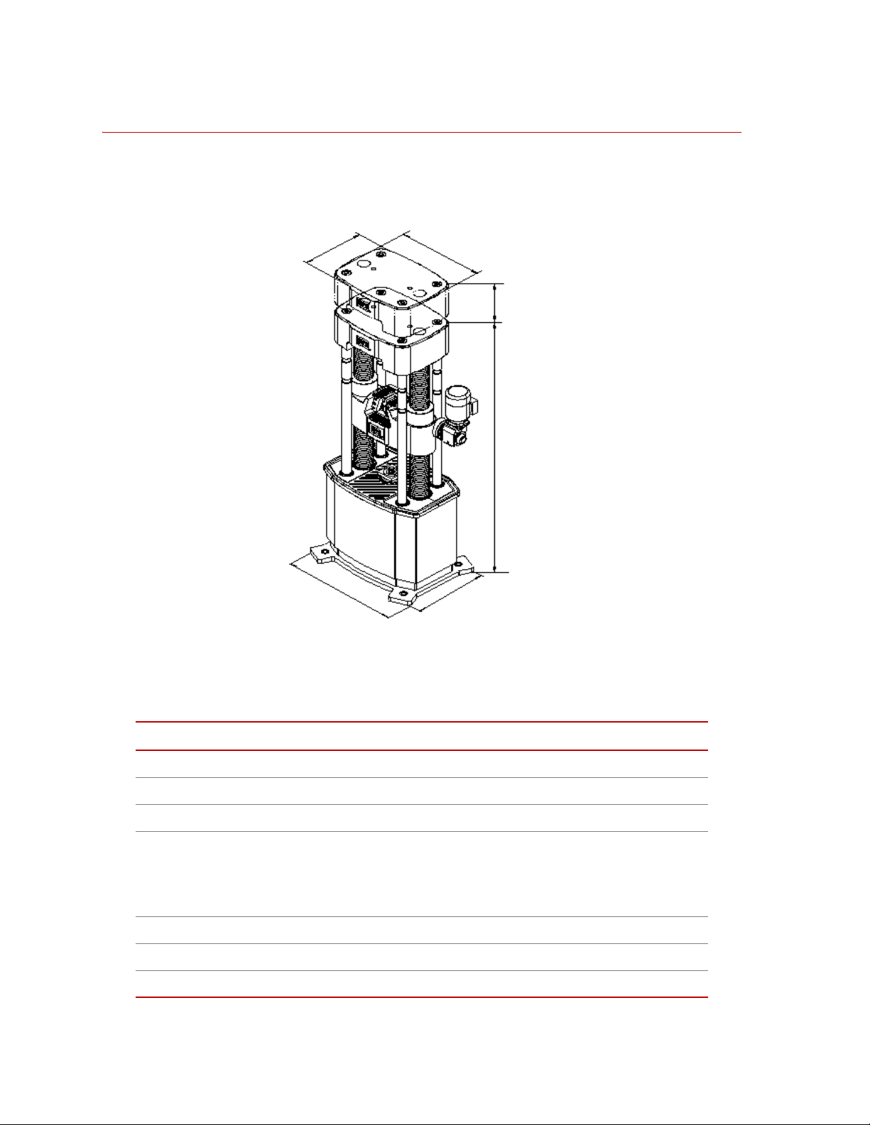
Integrated Operations Platform dimensions
Height 1900 mm
400 V 50 Hz / 480 V 60Hz
3~3W+PE
(74.80 in)
24
Introduction
Width 1040 mm
(40.94 in)
MTS Criterion™ Series 60 Product Manual
Page 25

Integrated Operations Platform Specifications (Continued)
Depth 765 mm
(30.11 in)
Weight 400 kg
(882 lb)
Specifications
MTS Criterion™ Series 60 Product Manual Introduction
25
Page 26
Specifications
Series 60 Load Frame
E
F
D
C
A
B
Dimensions
Frame
Series 60 Load Frame Dimensions
Width (A) 870 mm (34.25 in) 1170 mm (46.06 in) 1310 mm (51.57 in)
Depth (B) 725 mm (28.54 in) 800 mm (31.50 in) 910 mm (35.83 in)
Height (C)
Standard length (64.xxx)
Extended length (64.xxxE)
Actuator stroke (D) 150 mm (5.91 in) 200 mm (7.87 in) 250 mm (9.84 in)
Upper crosshead depth (E) 500 mm (19.69 in) 600 mm (23.62 in) 670 mm (26.38 in)
Upper crosshead width (F) 680 mm (26.77 in) 790 mm (31.10 in) 910 mm (35.83 in)
Introduction
26
64.305/64.305E 64.605/64.605E 64.106/64.106E
2074 mm (81.65
in)
2470 mm (97.24
in)
2390 mm (94.09 in)
2780 mm (109.45
in)
MTS Criterion™ Series 60 Product Manual
2720 mm (107.09 in)
3130 mm (123.23 in)
Page 27
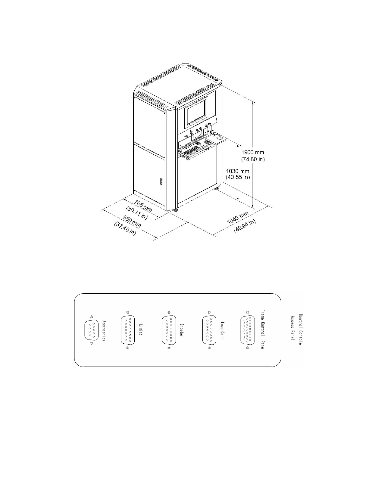
Integrated Operations Platform
Series 60 Integrated Operations Platform
Specifications
Control Console Access Panel Connector
Frame Control Panel This is intended to connect the Control Box to the Logic Board. This is used to
transmit the signal on the buttons of the Control Panel.
MTS Criterion™ Series 60 Product Manual Introduction
27
Page 28

Specifications
Pin assignment is as follows:
Pin Assignment
PIN SIGNAL
8 ESTOPIA-
9 ESTOPIB-
10 UP_CLOSE_SW
11 UP_OPEN_SW
12 LO_CLOSE_SW
13 LO_OPEN_SW
14 XHD_DOWN_SW
15 XHD _UP_SW
17 ESTOPIA+
18 ESTOPIB+
19 PANEL INO+
20 PAN E L I N O -
SHELL SHIELD
Load Cell This in intended to connect the stain-gauge load cell to the Insight Controller
Load Cell. It supports the TEDS feature to auto-identify and auto-calibrate the
load cell. Pin Assignment is as follows:
Pin Assignment
PIN SIGNAL
1 EX+
2 EX-
3 No Contact
4 FB+
5 FB-
6 No Contact
7 SHIELD
8 TEDS+
28
Introduction
9 No Contact
10 EXS+
11 No Contact
12 RCAL 1(FBR+)
13 RCAL 2(FBR-)
MTS Criterion™ Series 60 Product Manual
Page 29

Specifications
Pin Assignment (Continued)
P
IN SIGNAL
14 TEDS-
15 EXS-
Encoder This is intended to connect the frame displacement sensor to the encoder on the
Insight Controller. It is DC-powered and collects the digital encoder signals
frome the displacement sensor. Pin Assignment is as follows:
Pin Assignment
PIN SIGNAL
1 A+
2 A-
3 No Contact
4 GND
5 VCC
6 No contact
7 Shield
8 TEDS+
9 No Contact
10 B-
11 No Contact
12 I+
13 I-
14 TEDS-
15 B+
Limits This connector is intended to connect the frame limit and the logic board. It is
used to transmit the state signal of the frame limit. Pin assignment is as follows:
Pin Assignment
PIN SIGNAL
1 PISTON COM
2 PISTON NO
3 XHD UP NC
4 XHD LO COM
5 XHD LO NO
MTS Criterion™ Series 60 Product Manual Introduction
29
Page 30

Specifications
Pin Assignment (Continued)
P
IN SIGNAL
6 No Contact
7 No Contact
8 SHIELD
9 PISTON NC
10 XHD UP COM
11 XHD UP NO
12 XHD LO NC
13 No Contact
14 No Contact
15 No Contact
Accessories The additive connector is intended as the expanding part of the equipment. It is
used according to the request.
30
Introduction
MTS Criterion™ Series 60 Product Manual
Page 31

Safety Enclosure
A
B
C
Specifications
The safety enclosure has a four-sided frame structure to prevent projectile
injuries.
MTS Criterion Series 60 Safety Enclosure Specifications
MODEL WIDTH
(A)
64.305 1280 mm
(50.4 in)
64.605 1410 mm
(55.5 in)
64.106 1560 mm
(61.4 in)
64.305E 1280 mm
(50.4 in)
64.605E 1410 mm
(55.5 in)
64.106E 1560 mm
(61.4 in)
DEPTH
(B)
860 mm
(3
3.9 in)
890 mm
(35.0 in)
1030 mm
(40.6 in)
1360 mm
(53.5 in)
1390 mm
(54.7 in)
1530 mm
(60.2 in)
Note The safety enclosure is optional; it is available upon customer request.To
avoid projectile hazards, the doors of the enclosure must be closed
during tests.
HEIGHT
(GENERAL
FOUNDATION)
(C)
2050 mm
(80.7 in)
2400 mm
(94.5 in)
2713 mm
(106.8 in)
2450 mm
(96.5 in)
2800 mm
(110.2 in)
3120 mm
(122.8 in)
HEIGHT
(SUBSIDED
FOUNDATION)
(C)
- 66 kg
1710 mm
(67.3 in)
1897 mm
(74.7 in)
1760 mm
(69.3 in)
2110 mm
(83.1 in)
2344 mm
(92.3 in)
WEIGHT
(GENERAL
FOUNDATION)
(146 lb)
76 kg
(168 lb)
86 kg
(190 lb)
80 kg
(176 lb)
90 kg
(198 lb)
102 kg
(225 lb)
WEIGHT
(SUBSIDED
FOUNDATION)
-
70 kg
(154 lb)
80 kg
(176 lb)
64 kg
(141 lb)
74 kg
(163 lb)
83 kg
(183 lb)
MTS Criterion™ Series 60 Product Manual Introduction
31
Page 32

Specifications
Steps
64.605/64.305E Steps
64.106/64.605E Steps
64.106E Steps
32
Introduction
MTS Criterion™ Series 60 Product Manual
Page 33

MTS Criterion Series 60 Steps Specifications
Specifications
MODEL WIDTH
64.605 1410 mm
64.106 1570 mm
64.305E 1280 mm
64.605E 1410 mm
64.106E 1570 mm
Test Table Detail
DEPTH
(A)
(55.5 in)
(61.8 in)
(50.4 in)
(55.5 in)
(61.8 in)
Note The steps are optional; they are available upon customer request.
(B)
1200 mm
(47.2 in)
1510 mm
(59.5 in)
1000 mm
(39.4 in)
1550 mm
(61.0 in)
1900 mm
(74.8 in)
HEIGHT
(C)
450 mm
(17.7 in)
620 mm
(24.4 in)
400 mm
(15.7 in)
720 mm
(28.3 in)
1930 mm
(76.0 in)
WEIGHT
100 kg
(221 lb)
120 kg
(265 lb)
90 kg
(198 lb)
120 kg
(265 lb)
160 kg
(353 lb)
If you need to fit bend or shear fixtures, see the following figure for dimensions.
MTS Criterion™ Series 60 Product Manual Introduction
33
Page 34

Specifications
300 kN and 600 kN
Platen Transition Plate Detail
There are several kinds of threaded holes for mounting fixtures in the platen
transition plate.
34
Introduction
MTS Criterion™ Series 60 Product Manual
Page 35

Specifications
1000 kN
MTS Criterion™ Series 60 Product Manual Introduction
35
Page 36

Specifications
36
Introduction
MTS Criterion™ Series 60 Product Manual
Page 37

Safety
General Safety Practices
This section provides information about safety issues that pertain to static
hydraulic systems in general. These issues include statements to the intended use
and foreseeable misuse of the system, the hazard zone, definition for the
graphical hazard labeling that is affixed to your product, and other (more general)
safety information that relates to the high-pressure and high-performance
characteristics of MTS static hydraulic systems.
MTS test systems are designed to generate motions and forces and impart these
motions and forces into a test specimen.
When you prepare to operate the system and during system operation, ensure the
following:
• Do not use or allow personnel to operate the system who are not
• Do not disable safety components or features (including limit detectors).
experienced, trained, or educated in the inherent dangers associated with
high-performance servohydraulics and who are not experienced, trained, or
educated with regard to the intended operation as it applies to this test
system.
• Do not attempt to operate the system without appropriate personal safety
gear (for example, hearing, hand, and eye protection).
• Do not apply improper energy levels for the system. Refer to the Integrated
Operation Platform specifications.
• Do not test a specimen that exceeds the minimum (if applicable) or
maximum allowable mass. Refer to the system specifications.
• Do not use specimens that are combustible, flammable, pressurized, or
explosive.
• Do not use humans as specimens or allow humans to ride in or on the test
specimen or the test system for any purpose unless the system is man-rated
and all associated safety conditions are strictly enforced.
• Do not modify the system or replace system components using parts that are
not MTS component parts or effect repairs using parts or components that
are not manufactured to MTS specifications.
• Do not operate the system in an explosive atmosphere.
• Do not use the system in a test area where uncontrolled access to the test
system is allowed when the system is in operation.
If you have system-related responsibilities (that is, if you are an operator, service
engineer, or maintenance person), you should study safety information carefully
before you attempt to perform any test system procedure.
MTS Criterion™ Series 60 Product Manual Safety
37
Page 38

You should receive training on this system or a similar system to ensure a
thorough knowledge of your equipment and the safety issues that are associated
with its use. In addition, you should gain an understanding of system functions
by studying the other manuals supplied with your test system. Contact MTS for
information about the content and dates of training classes that are offered.
It is very important that you study the following safety information to ensure that
your facility procedures and the system’s operating environment do not
contribute to or result in a hazardous situation. Remember, you cannot eliminate
all the hazards associated with this system, so you must learn and remain aware
of the hazards that apply to your system at all times. Use these safety guidelines
to help learn and identify hazards so that you can establish appropriate training
and operating procedures and acquire appropriate safety equipment (such as
gloves, goggles, and hearing protection).
Each test system operates within a unique environment which includes the
following known variables:
• Facility variables (facility variables include the structure, atmosphere, and
utilities)
• Unauthorized customer modifications to the equipment
• Operator experience and specialization
• Test specimens
Because of these variables (and the possibility of others), your system can
operate under unforeseen circumstances that can result in an operating
environment with unknown hazards.
Improper installation, operation, or maintenance of your system can result in
hazardous conditions that can cause death, personal injury, or damage to the
equipment or to the specimen. Common sense and a thorough knowledge of the
system’s operating capabilities can help to determine an appropriate and safe
approach to its operation.
Safety Practices Before System Operation
Before you apply power to the test system, review and complete all of the safety
practices that are applicable to your system. The goal, by doing this, is to
improve the safety awareness of all personnel involved with the system and to
maintain, through visual inspections, the integrity of specific system
components.
Read all manuals Study the contents of this manual and the other manuals provided with your
system before attempting to perform any system function for the first time.
Procedures that seem relatively simple or intuitively obvious can require a
complete understanding of system operation to avoid unsafe or dangerous
situations.
Locate and read
hazard placards/labels
Find, read, and follow the hazard placard instructions located on the equipment.
These placards are placed strategically on the equipment to call attention to areas
such as known crush points and electrical voltage hazards.
38
Safety
MTS Criterion™ Series 60 Product Manual
Page 39

Locate lockout/tagout
points
Know where the lockout/tagout point is for all of the supply energies associated
with your system. This includes the hydraulic, pneumatic, electric, and water
supplies (as appropriate) for your system to ensure that the system is isolated
from these energies when required.
Know facility safe
procedures
Locate Emergency
Stop buttons
Most facilities have internal procedures and rules regarding safe practices within
the facility. Be aware of these safe practices and incorporate them into your daily
operation of the system.
Know the location of all the system Emergency Stop buttons so that you can
stop the system quickly in an emergency. Ensure that an Emergency Stop button
is located within 2 meters (6 feet) of the operator at all times.
Know controls Before you operate the system for the first time, make a trial run through the
operating procedures with the power off. Locate all hardware and software
controls and know what their functions are and what adjustments they require. If
any control function or operating adjustment is not clear, review the applicable
information until you understand it thoroughly.
Have first aid available Accidents can happen even when you are careful. Arrange your operator
schedules so that a properly trained person is always close by to render first aid.
In addition, ensure that local emergency contact information is posted clearly and
in sight of the system operator.
Know potential crush
and pinch points
Know electrical
hazards
Be aware of potential crush and pinch points on your system and keep personnel
and equipment clear of these areas.
When the system electrical power is turned on, minimize the potential for
electrical shock hazards. Wear clothing and use tools that are properly insulated
for electrical work. Avoid contact with exposed wiring or switch contacts.
Whenever possible, turn off electrical power when you work on or in proximity
to any electrical system component. Observe the same precautions as those given
for any other high-voltage machinery.
Keep bystanders
safely away
Keep bystanders at a safe distance from all equipment. Never allow bystanders to
touch specimens or equipment while the test is running.
Wear proper clothing Do not wear neckties, shop aprons, loose clothing or jewelry, or long hair that
could get caught in equipment and result in an injury. Remove loose clothing or
jewelry and restrain long hair.
Check bolt ratings and
torques
To ensure a reliable product, fasteners (such as bolts and tie rods) used in MTSmanufactured systems are torqued to specific requirements. Overtorquing or
undertorquing a fastener can create a hazardous situation due to the high forces
and pressures present in MTS test systems.
On rare occasions, a fastener can fail even when it is correctly installed. Failure
usually occurs during torquing, but it can occur several days later. Failure of a
fastener can result in a high velocity projectile. Therefore, it is a good practice to
avoid stationing personnel in line with or below assemblies that contain large or
long fasteners.
MTS Criterion™ Series 60 Product Manual Safety
39
Page 40

Practice good
housekeeping
Keep the floors in the work area clean. Do not leave tools, fixtures, or other items
not specific to the test, lying about on the floor, system, or test table.
Protect hoses and
cables
Protect electrical cables from excessive temperatures that can cause the cables to
harden and eventually fail. Ensure that all cables have appropriate strain relief
devices installed at the cable and near the connector plug. Do not use the
connector plug as a strain relief.
Protect all system hoses and cables from sharp or abrasive objects that can cause
the hose or cable to fail. Never walk on hoses or cables or move heavy objects
over them. Consider system layout and route hoses and cables away from areas
that expose them to possible damage.
When removing hydraulic hoses for equipment repair or changing testing
components (for example, hydraulic grips), make sure to cap the hose ends to
avoid spilling hydraulic fluid.
Record changes If you change any operating procedure, write the change and the date of the
change in the appropriate manual.
Provide test area
guards
Do not disable safety
devices
Use protective guards such as cages, enclosures, and special laboratory layouts
when you work with hazardous test specimens (for example, brittle or
fragmenting materials or materials that are internally pressurized).
Your system might have active or passive safety devices installed to prevent
system operation if the device indicates an unsafe condition. Do not disable such
devices as it can result in unexpected system motion.
Use appropriately
sized fuses
Provide adequate
lighting
Provide means to
access out-of-reach
components
Ensure equipment is
secure
Whenever you replace fuses for the system or supply, ensure that you use a fuse
that is appropriately sized and correctly installed. Undersized or oversized fuses
can result in cables that overheat and fuses that explode. Either instance creates a
fire hazard.
Ensure adequate lighting to minimize the chance of operation errors, equipment
damage, and personal injury. You need to see what you are doing.
Make sure you can access system components that might be out of reach while
standing on the floor. For example, ladders or scaffolding might be required to
reach grips on tall load units.
Make sure the equipment is secure or provide vibration isolation. Some testing
can be performed at resonant frequencies that might cause the equipment to
vibrate and move during testing.
Safety Practices While the System Is in Operation
Wear appropriate
personal protection
Wear eye protection when you work with testing machines, breakable specimens,
or when anything characteristic to the specimen could break apart.
Wear ear protection when you work near electric motors, pumps, or other devices
that generate high noise levels. Some systems can create sound pressure levels
that exceed 70 dbA during operation.
40
Safety
MTS Criterion™ Series 60 Product Manual
Page 41

Wear appropriate personal protection equipment (gloves, boots, suits, respirators)
whenever you work with fluids, chemicals, or powders that can irritate or harm
the skin, respiratory system, or eyes.
Expect specimen
temperature changes
Handle chemicals
safely
Know system
interlocks
During cyclic testing, the specimen temperature can become hot enough to cause
burns. Wear personal protection equipment (gloves) when handling specimens.
Whenever you use or handle chemicals (for example, cleaning fluids, hydraulic
fluid, batteries, contaminated parts, electrical fluids, and maintenance waste),
refer to the appropriate MSDS documentation for that material and determine the
appropriate measures and equipment required to handle and use the chemical
safely. Ensure that the chemical is disposed of appropriately.
Interlock devices should always be used and properly adjusted. Interlock devices
are designed to minimize the chance of accidental damage to the test specimen or
the equipment. Test all interlock devices for proper operation immediately before
a test. Do not disable or bypass any interlock devices as doing so could allow
crosshead movement regardless of the true interlock condition.
Know system limits Never rely on system limits, such as mechanical limits or software limits, to
protect you or any personnel. System limits are designed to minimize the chance
of accidental damage to test specimens or to equipment. Test all limits for proper
operation immediately before a test. Always use these limits and adjust them
properly.
Do not disturb sensors Do not bump, wiggle, adjust, disconnect, or otherwise disturb a sensor (such as
an accelerometer or extensometer) or its connecting cable when power is applied.
Ensure secure cables Do not change any cable connections when electrical power is applied. If you
attempt to change a cable connection while the system is in operation, an open
control loop condition can result. An open control loop condition can cause a
rapid, unexpected system response which can result in severe personal injury,
death, or damage to equipment. Also, ensure that all cables are connected after
you make any changes in the system configuration.
Stay alert Avoid long periods of work without adequate rest. In addition, avoid long periods
of repetitious, unvarying, or monotonous work because these conditions can
contribute to accidents and hazardous situations. If you are too familiar with the
work environment, it is easy to overlook potential hazards that exist in that
environment.
Stay clear of moving
equipment/avoid crush
points
MTS Criterion™ Series 60 Product Manual Safety
Stay clear of mechanical linkages, connecting cables, and hoses that move
because you can get pinched, crushed, tangled, or dragged along with the
equipment. High forces generated by the system can pinch, cut, or crush anything
in the path of the equipment and cause serious injury. Stay clear of any potential
crush points. Most test systems can produce sudden, high-force motion. Never
assume that your reactions are fast enough to allow you to escape injury when a
system fails.
41
Page 42

Know the causes of
Ball relief valve of the actuator
unexpected crosshead
motions
The high force and velocity capabilities of MTS systems can be destructive and
dangerous (especially if crosshead motion is unexpected). The most likely causes
of unexpected crosshead response are operator error and equipment failure due to
damage or abuse (such as broken, cut, or crushed cables and hoses; shorted wires;
overstressed feedback devices; and damaged components within the control
loop). Eliminate any condition that could cause unexpected crosshead motion.
Do not use RF
transmitters
Operations for b all
relief valves
Keep radio frequency (RF) transmitters away from the workstation computers,
remote terminals, and consoles. Intense RF fields can cause erratic operation of
the more sensitive circuits in the system.
Rotate the handle of ball valve and make sure the handle is parallel with the
pipe,that is the "open" position.
Safety
42
MTS Criterion™ Series 60 Product Manual
Page 43

Hazard Labels
Ball Relief Valves(4pcs) for Grips
LABEL DESCRIPTION
The following hazard labels and icons are located on the MTS Criterion Series 60
frames.
Lift the machine upright.
Moving parts present.
Moving parts can crush and cut.
Keep hands away from moving parts.
MTS Criterion™ Series 60 Product Manual Safety
43
Page 44

Flying objects.
Danger of eye injury.
Wear safety glasses.
Tip-over hazard.
Use outriggers when machine is standalone.
Do not start, operate, or service machine until you read
and understand the operator’s manual.
Failure to do so could result in serious injury.
To turn the pulley, manually move the crosshead upward
and downward.
Pulleys can be turned by hand when power is disabled.
WEEE The Waste Electrical and Electronic Equipment (WEEE) symbol ( ) means
that the controller and its electronic parts must not be disposed of as unsorted
municipal waste. Proper disposal is required by approved electronic waste
collection agencies. Customers in the EC region who desire to return an end-oflife controller and its electronic parts are encouraged to contact your local MTS
Systems Sales/Service Offices for instructions.
Customer should follow internal safety policies for safe disposal of parts of the
machine. Refer to MSDS for oils and greases that are used on the machine.
44
Safety
MTS Criterion™ Series 60 Product Manual
Page 45

Installation
Contents Lifting and Moving Overview 46
Moving Frames and Integrated Operations Platform 48
Installing the Optional Safety Enclosure 59
Installing the Steps 62
Controller Connections 63
Connecting Hoses 72
Adding Oil 73
MTS Criterion™ Series 60 Product Manual Installation
45
Page 46

Lifting and Moving Overview
WARNING
Lifting and Moving Overview
This section provides guidelines for moving and installing your MTS Criterion
Series 60 Test Systems.
Unless otherwise specified, it is your responsibility to off-load, unpack, and
move the equipment to the final location on your premises. This includes
insurance and safety responsibility.
Before moving the machine from the receiving area to its final location, be sure
to check the dimensions of all doors and passages through which the machine
will travel. Refer to the specification tables in the “Introduction” section of this
manual for dimensions.
To reliably and safely use the equipment, handle it according to the instructions.
Check for any crate damages upon the machine arrival. If you find any damage,
contact MTS as soon as possible and describe the details in the Commissioned
Shipment Receipt.
The MTS Criterion Series 60 frames are heavy.
Moving the frame using improper procedures can injure personnel (for
example strained muscles and back injuries) or damage the frame.
When lifting the frame, take the appropriate precautions to prevent injuries to
yourself. Moving and positioning the MTS Criterion Series 60 frames must be
performed by qualified personnel only.
Do not allow the load frame to drop or topple.
Make sure that your chains, slings, and crane have a working capacity greater
than the load frame’s weight (see the following table).
Make sure that the lifting hoist rings are tight.
Make sure that the crosshead locking bolts are fully tightened.
Lift the load frame only high enough to clear its pallet.
Operate the crane smoothly to prevent breaking shocks to the sling.
MTS Criterion Series 60 frames weigh from 1950 to 5400 kg (4300 to 11905 lb).
Other apparatus such as packaging and accessories add to the overall weight. If
you have any questions, call MTS.
46
Installation
MTS Criterion™ Series 60 Product Manual
Page 47

MODEL LOAD
F
RAME
Lifting and Moving Overview
The following table lists the approximate weight of each load frame model,
Integrated Operations Platform, and optional parts with and without the crate.
The weight specification is for lifting and moving purposes. The weight of
accessories and special fixtures must be added. The actual shipping weight must
be determined by a scale.
Weight Specifications
INTEGRATED
O
PERATIONS
PLATFORM
SAFETY
E
NCLOSURE
(O
PTIONAL)
CRATED
L
OAD
F
RAME
STEPS
(OPTIONAL)
CRATED
L
OAD
F
RAME &
S
AFETY
E
NCLOSURE
CRATED
I
NTEGRATED
O
PERATIONS
P
LATFORM
CRATED
S
TEPS
64.305 1950 kg
(4299 lb)
64.605
Subsided
Foundation
64.106
Subsided
Foundation
64.305E
Subsided
Foundation
64.605E
Subsided
Foundation
3150 kg
(6945 lb)
5250 kg
(11574
2003 kg
(4416 lb)
3254 kg
(7174 lb)
lb)
400 kg
(882 lb)
400 kg
(882 lb)
400 kg
(882 lb)
400 kg
(882 lb)
400 kg
(882 lb)
66 kg
(146 lb)
76 kg
(168 lb)
70 kg
(154 lb)
86 kg
(190 lb)
80 kg
(176 lb)
80 kg
(176 lb)
64 kg
(141 lb)
90 kg
(198 lb)
74 kg
(163 lb)
2086 kg
(4599 lb)
3332 kg
(7346 lb)
5498 kg
(12121
lb)
2107 kg
(4645 lb)
3360 kg
(7408 lb)
- 2152 kg
100 kg
(221 lb)
120 kg
(265 lb)
90 kg
(198 lb)
120 kg
(265 lb)
(12312 lb)
(12110 lb)
(4745 lb)
3408 kg
(7515 lb)
3326 kg
(7334 lb)
5584 kg
5792 kg
2187 kg
(4822 lb)
2019 kg
(4611 lb)
3450 kg
(7607 lb)
3344 kg
(7374 lb)
480 kg
(1058 lb)
480 kg
(1058 lb)
480 kg
(1058 lb)
480 kg
(1058 lb)
480 kg
(1058 lb)
-
250 kg
(551
lb)
300 kg
(662
lb)
250 kg
(551
lb)
300 kg
(662
lb)
64.106E
Subsided
Foundation
MTS Criterion™ Series 60 Product Manual Installation
5400 kg
(11905
lb)
400 kg
(882 lb)
102 kg
(225 lb)
83 kg
(183 lb)
5530 kg
(12192
lb)
160 kg
(353 lb)
5632 kg
(12419 lb)
5511 kg
(12152 lb)
480 kg
(1058 lb)
350 kg
(772
lb)
47
Page 48

Moving Frames and Integrated Operations Platform
WARNING
Moving Frames and Integrated Operations Platform
The packing materials may shift and loosen while moving the frame.
Moving the frame with loose packing materials may cause injury to
personnel and damage to the frame.
Remove the packing materials before moving the frame.
Note Before the FSE arrival, it is the customer’s responsibility to arrange the
off-loading, unpacking, and moving of the testing system to the final site
location.
Note If the testing system needs to be moved to another location after initial
installation, it is the customer’s responsibility to move and remount the
system.
Machine Location and Ventilation
To ensure proper ventilation, locate the load frame approximately 100 mm (4 in)
away from adjacent walls and equipment. Do not block the vent holes of the
machine.
For comfortable working conditions and proper equipment operation, heat
dissipation of the equipment must be considered in providing adequate heating or
air conditioning in the laboratory area. Heat dissipation can be approximated by
summing the heat losses going into the room (1 kVA is equivalent to 860 kcal/hr
[3,400 Btu/hr]) and the gains from other sources such as furnaces and personnel.
48
Installation
MTS Criterion™ Series 60 Product Manual
Page 49

Moving the Load Fame
Unloading
The customer will be responsible for all the unloading process if no Unloading
Service is purchased. In case of special agreement, an MTS field service engineer
can monitor the unloading, storage, and transportation process.
To unload the load frame:
1. Unload the load frame with reference to the lifting position marker
2. Choose suitable slings according to the weight table.
3. Lift the crate with suitable slings as shown in the following figure.
4. Pay attention to the gravity center marker on the crate to ensure
stable and balanced lifting.
Moving Frames and Integrated Operations Platform
and the gravity center marker .
Note If the machine will not be installed right away, store it in a steady, dry and
corrosion free place. MTS is not responsible for damages caused by
improper storage.
MTS Criterion™ Series 60 Product Manual Installation
49
Page 50

Moving Frames and Integrated Operations Platform
Moving the Load Unit to Its Final Location
To move the load frame:
1. Remove the cover board. If you ordered the safety enclosure, take it out and
store it in a suitable place (The MTS field service engineer will install it for
you). Take off the side boards. Remove the mounting bolts for the frame.
Attach customer-supplied hoist rings (M30 for C64.305 / C64.305E, M36
for C64.605 /C64.605E and C64.106 /C64.106E) to the frame.
2. Tie suitable slings to the hoist rings and lift the frame. Remove the pallet
under the frame.
Note The clamps attached should not be removed from the frame.
50
Installation
MTS Criterion™ Series 60 Product Manual
Page 51

Moving Frames and Integrated Operations Platform
3. Put the frame base on a mat and let the frame lay horizontally, remove the
lifting rings on base.
Note When the frame rises, keep a safe distance from the frame to avoid
personal injury.
4. Use a crane to slowly raise the frame to its upright position. As the frame
rises, keep moving the crane to keep the slings as straight as possible. As
there will be shake when the frame raise, please put the side board
(Unpacked from the frame package) under the frame to avoid frame
damages.
MTS Criterion™ Series 60 Product Manual Installation
51
Page 52

Moving Frames and Integrated Operations Platform
5. When the frame is stable in the upright position, lift it to the final location.
6. Move the load unit to its final location and secure the frame to the
foundation. Refer to either
“Moving the Load Unit with a Forklift” on page
53 or “Moving the Load Unit with an Overhead Crane” on page 53.
52
Installation
MTS Criterion™ Series 60 Product Manual
Page 53

Moving the Load Unit with a Forklift
If a fork lift is used, perform the following:
1. Adjust the fork distance and height, make them suitable to extend under the
lower crosshead.
2. Put protective rubber or cloth on the forks and extend them under the lower
crosshead. The two forks should be level and equally loaded.
Note Verify the capacity of the lifting fork.Be absolutely careful not to stop or
transit within the field of action of the lifting fork.
3. Raise the load frame slowly and steadily to a suitable height and move the
load frame to the foundation slowly and steadily.
4. Secure the load frame to the foundation; “Securing the Load Unit” on page
54.
Moving Frames and Integrated Operations Platform
Moving the Load Unit with an Overhead Crane
If an overhead crane is used, perform the following:
1. Choose suitable slings according to the load frame weight.
2. Attach the slings to the customer-supplied lifting ring on the upper
crosshead.
Note Verify the capacity of the overhead crane.Be absolutely careful not to
stop or transit within the field of action of the overhead crane.
MTS Criterion™ Series 60 Product Manual Installation
53
Page 54

Moving Frames and Integrated Operations Platform
Do not exceed 30
o
Supporting
Wood
3. Raise the hook slowly to lift the load frame only high enough to move.
4. Slowly and steadily move the load frame to the foundation.
5. Secure the load frame to the foundation; see “Securing the Load Unit” on
page 54.
Securing the Load Unit
Installation
54
To secure the load unit to the foundation:
1. Put the anchor bolts into the bolt holes. The top of the bolts should be lower
than the top of the foundation.
2. Align the anchor bolt holes on the load frame base with that of the
foundation, and slowly put down the load frame.
3. Put the anchor bolts, which are in the foundation anchor bolt holes, through
the load frame anchor bolt holes. Put the flat washers, spring washers, and
nuts on the bolts leaving 2-4 threads of the bolts on top of the nuts.
4. Center the anchor bolts and grout the anchor holes with cement mixtures.
Keep the anchor bolts at the center of the holes while grouting.
5. Grout the cement mixture to the same level of the groundwork and scrape it
level. After curing the foundation for a while, tighten the anchor bolt nuts.
MTS Criterion™ Series 60 Product Manual
Page 55

Moving Frames and Integrated Operations Platform
Torque Measurements
Model Bolt Diameter Tor que
C64.305/
C64.305E
C64.605/
C64.605E/
C64.106/
C64.106E
Note Diagonally tighten the nuts to avoid non-uniform load.
24 mm
(0.94 in)
30 mm
(1.18 in)
160 N•m
(118 lbf•ft)
320 N•m
(236 lbf•ft)
MTS Criterion™ Series 60 Product Manual Installation
55
Page 56

Moving Frames and Integrated Operations Platform
Moving the Integrated Operations Platform
Unloading
Choose suitable slings according to the Integrated Operations Platform and crate
weight. Wrap the sling through the crate pallet and raise it.
Moving the Integrated Operations Platform to Its Final Location
To move the Integrated Operations Platform:
1. Unpack the Integrated Operations Platform.
2. Choose suitable chains according to the Integrated Operations Platform
weight.
3. Attach the chains to the customer-supplied hoist rings (M16) on the
Integrated Operations Platform and hang the other end to the hook.
56
Installation
MTS Criterion™ Series 60 Product Manual
Page 57

Moving Frames and Integrated Operations Platform
Do not exceed 30
o
Hoist Rings M16
Note Verify the capacity of the overhead crane.Be absolutely careful not to
stop or transit within the field of action of the overhead crane.
4. Raise the hook slowly and move the platform to its final location.
5. Put the platform down and take off the chains. Adjust the levelness with the
feet under the platform.
6. Contact MTS Systems Corporation to arrange for installation services.
Note If you can guarantee the safety, other tools like platform vehicle and
pallet jack can also be used to move the Integrated Operations Platform
to its final location.Other equipment, such as a platform vehicle and
pallet jack, can also be used to move the Integrated Operations Platform
to its final location. Safety guidelines for these methods are not provided
in this manual, but you will need to be aware of safety precautions if
using these methods.
MTS Criterion™ Series 60 Product Manual Installation
57
Page 58

Moving Frames and Integrated Operations Platform
Unloading the Steps
If you have purchased steps, unload them using the correct procedures (see the
Integrated Operations Platform unloading for reference). Store them in a suitable
place and wait for an MTS field service engineer to install them.
58
Installation
MTS Criterion™ Series 60 Product Manual
Page 59

Installing the Optional Safety Enclosure
1
2
3
4
5
6
7
Installing the Optional Safety Enclosure
The Material Testing System and optional equipment are supplied with Product
Information Manuals that allow them to be assembled and integrated to work as
assemblies of machinery.
Customer must evaluate risks due to ejected parts or materials from the test
specimens. If Test Area Guard is not selected by customer, then for protection
against ejected parts or materials from test specimens and to control access to the
machinery, the Customer must provide a Test Area Guard to protect personnel.
① Front ② Front door ③ Handle ④ Back ⑤ Back door ⑥ Connecting rod ⑦
MTS Criterion™ Series 60 Product Manual Installation
Adjustable foot
If you have purchased the safety enclosure, it should be installed per the
following
engineer).
procedure (Generally the enclosure is installed by MTS field service
59
Page 60

Installing the Optional Safety Enclosure
1. Install the ① front part of the safety enclosure to the front of the load unit
and make it symmetric around the load unit. Level the enclosure with the
adjustable feet.
60
Installation
MTS Criterion™ Series 60 Product Manual
Page 61

Installing the Optional Safety Enclosure
Llifting Pads
2. Install the ④ Back and the ⑥ Connecting rod.
3. Install the ②Front door,③Handle, and ⑤Back door, and remove the lifting
pads.
MTS Criterion™ Series 60 Product Manual Installation
61
Page 62

Installing the Steps
Screw Connection
Screw Connection
Attach together with
screws provided with
steps.
Installing the Steps
If you have purchased the steps, they should be installed as below. (Generally the
steps are installed by MTS field service engineer)
62
Installation
MTS Criterion™ Series 60 Product Manual
Page 63

Controller Connections
CAUTION
Connecting the Main Power
MTS Criterion Series 60 systems use an integrated power cord.
Check the power supply before connecting the testing system to it.
An unqualified power supply can cause injury to personnel or damage to
the testing system.
Confirm that the power supply meets MTS' power requirements.
Note Electrical connections must be made by qualified personnel and conform
to local codes and regulations. Local electrical codes supersede any
information found here.
Controller Connections
Electrical connections must be made by qualified personnel and is their
responsibility for using the proper power disconnect along with the correct size
and type of wire and conduit that conforms to all their local electrical codes when
connecting the machine to the building′s main power.
Wire Sizes A main powercable (3W+PE) of 5 meters is provided on the Criterion Series 60
system. The wire type is 4×4 mm
2
(4×12 AWG).
Electrical disconnect The customer is responsible for providing a power disconnect that is easy to
operate and easy to reach. Usually this is integrated into a wall mounted electrical
junction box with over current protection. It must also meet IEC 60947-1 and
IEC 60947-3 standards.
Recommended circuit breakers are of the thermal magnetic type with
characteristics suitable for large inductive loads (D-type trip characteristic).
For the electrical box, the over current device must be Branch circuit rated.
Machine-Specific Requirements
64.305/64.305E • Power 3.75 kW.
• Current 11.6 A maximum.
64.605/64.605E • Power 5.2 kW.
• Current 15 A maximum.
64.106/64.106E • Power 5.2 kW.
• Current 15 A maximum.
MTS Criterion™ Series 60 Product Manual Installation
63
Page 64

Controller Connections
CAUTION
Installing Cables
Controller Connectors
To maintain EMC compliance and help ensure optimal performance, MTS
recommends ordering all system cables from MTS. Cables should be installed so
that they are protected from conditions that could damage the cable.
Exercise care when connecting cables. Ensure that you use the correct cables and
that all connections are secure. When you are finished, double-check to ensure
that all components are connected properly.
Check the power before connecting cables.
Connecting cables with power applied may cause injury to personnel or
damage to the equipment.
Ensure that the power is off before connecting cables.
64
Installation
J1 USB This is a standard USB 2.0 connector that accepts a USB-B cable connector and
connects the computer. This provides a communications interface between the
testing software on the PC and the controller. This is used to allow the software to
change settings in the controller and receive data from the controller.
MTS Criterion™ Series 60 Product Manual
Page 65

Controller Connections
J2 Handset This is intended to interface to the handset. Specifics for this connector are:
• 12 V output power with 200 mA current limit
• RS422 driver (differential)
• RS422 receiver (differential)
• Interlock input. Handset shorts between INTLK+ and INTLK- when it is
connected.
• 8-pin RJ-45 connector
8-Pin Assignment
PIN SIGNAL
1 Transmit +
2 Transmit -
3 +12V
4 INTLK +
5 INTLK -
6 Analog GND
7 Receive +
8 Receive -
J3 Interlock This is intended to connect to a test area enclosure switch that opens when the
door is opened. If not used, a jumper plug (p/n 049-635-901) must be installed. If
you are building a cable, the maximum length is 30.48 m (100 ft) with 24 gauge
wire. The switch should be wired normally closed, such that when the switch
opens, an interlock is generated.
MTS Criterion™ Series 60 Product Manual Installation
65
Page 66

Controller Connections
J4 Encoder This connector is intended for an encoder-based extensometer. Specifics for this
connector are:
• Power: +5 V +/- 0.25 V at 100 mA max
• Signals: Quadrature A and B with index I
• Logic: Differential receivers (can connect single ended)
• Maximum Rate: 100,000 lines/sec = 400,000 counts/sec
Pin assignment is as follows:
Pin Assignment
PIN SIGNAL
1 TEDS data
2 A+
3 A-
4 +5 V
5 I+
6 I-
7 Analog GND
8 B+
9 B-
10 TEDS ground
66
Installation
MTS Criterion™ Series 60 Product Manual
Page 67

Controller Connections
J5 Digital I/O Digital I/O signals include three optically isolated inputs, three optically isolated
outputs, and 12 V power. Functions of each digital input or output are software
selectable. J5 should be connected to J12 to make the controller board and
interface board communicate with each other. Pin assignment is as follows:
Pin Assignment
PIN SIGNAL
1 In 1+
2 In 2+
3 In 3+
4 Out 1+
5 Out 2+
6 Out 3+
7 No Contact
8 +12V
9 In 1-
10 In 2-
11 In 3-
12 Out 1-
13 Out 2-
14
15 Analog GND
Out 3-
J6 and J7 Monitor Two monitor connectors are provided. There are several possible uses for analog
monitor outputs: external data acquisition, tuning, troubleshooting, and so forth.
For tuning, it is desirable to monitor command and feedback, or command and
error, simultaneously while changing the controller parameters. Therefore, two
monitor outputs are provided. Specifics for these connectors are:
• Analog +/-10.5 V
• Calibrated to +/-10 V
• 16-bit resolution minimum
• BNC connectors
MTS Criterion™ Series 60 Product Manual Installation
67
Page 68

Controller Connections
J8 and J9 DC
Conditioner
Two DC Conditioner connectors are provided. The two application-specific
transducers might be biaxial strain gage base extensometers. With external
completion resistors, the DC conditioners could be used with quarter bridge
strain gages. Pin assignment is as follows:
Pin Assignment
PIN SIGNAL
1 TEDS data
2 EX+
3 EX-
4 FB-
5 RCAL1 (FBR+)
6 RCAL2 (FBR-)
7 FB+
8 EXS-
9 EXS+
10 TEDS ground
J10 Aux Pwr This is an auxiliary power connector. It can provide power supply to
external devices. Pin assignment is as follows:
Pin Assignment
PIN SIGNAL
1 +12V (Combined with
Pin 6
2 AGND
3 -12V
4 PGND
5 +5V
6 +12V ( Combined with
Pin 1)
7 AGND
8 DGND
9 +24V
68
Installation
MTS Criterion™ Series 60 Product Manual
Page 69

Controller Connections
J11 Guard This connector is intended to connect to a test area enclosure switch that opens
when the door is opened. C60 series do not use this function, a jumper plug must
be installed. A jumper plug must be installed. If you are building a cable, the
maximum length is 30.48 m (100 ft) with 22 AWG. The switch should be wired
normally closed, such that when the switch opens, an interlock is generated. Pin
assignment is as follows:
GUARD = test area guard switch with two contacts.
GUARD_CONFIG = configuration jumpers in the cable.For speed limit when
test are guard door open jumper Guard_config1+ to Guard_config1- and
Guard_config2+ to Guard_config2-. For interlock when guard door open leave
Guard_config unconnected.
Pin Assignment
PIN SIGNAL
1 GUARD 1A+
2 GUARD2A+
3 GUARD_CONFIG1+
4 No Contact
5 GUARD_CONFIG2-
6 GUARD1A -
7 GUARD2A-
8 GUARD_CONFIG1
9 GUARD_CONFIG2+
J12 Digital I/O The connector is the MTS Insight digital I/O control connector. It is connected
Digital I/O connector through a jumper.
with J5
J13 Digital I/O User Digital I/O signals include three optically isolated inputs, three optically isolated
outputs, and 12 V power. Functions of each digital input or output are software
selectable. A typical example might be connecting an external switch; see
“Additional Digital I/O Information” on page 93. Pin assignment is as follows:
Pin Assignment
PIN SIGNAL
1 DIN 1+
2 DIN 2+
3 DIN 3+
4 OUT 1+
5 OUT 2+
6 OUT 3+
MTS Criterion™ Series 60 Product Manual Installation
69
Page 70

Controller Connections
Pin Assignment (Continued)
P
IN SIGNAL
7 No Contact
8 VCC
9 DIN 1-
10 DIN 2-
11 DIN 3-
12 OUT 1-
13 OUT 2-
14 OUT 3-
15 AGND
J14 Emergency Stop This connector is intended to connect to a remote Emergency Stop switch. If not
used, a jumper plug must be installed. If you are building a cable, the maximum
length is 30.48 m (100 ft) with 18 AWG. The switch should be wired normally
closed, such that when the switch is pressed, an interlock is generated.
Pin assignment is as follows:
ESTOP3 = emergency stop switch with two sets of contacts (optional remotely
mounted).
ESTOP_OUT = optional ESTOP output for accessory, includes two contact
outputs and one feedback.
Pin Assignment
PIN SIGNAL
1 ESTOPB_OUT-
2 No Contact
3 ESTOP_OUT_MONITOR-
4 ESTOP_OUT_MONITOR+
5 ESTOP3B+
6 ESTOPA_OUT-
7 ESTOP3B-
8 ESTOP3A+
9 ESTOPB_OUT+
10 No Contact
11 No Contact
12 No Contact
13 ESTOP3A-
70
Installation
MTS Criterion™ Series 60 Product Manual
Page 71

Controller Connections
Pin Assignment (Continued)
P
IN SIGNAL
14 ESTOPA_OUT+
15 No Contact
Power OK Power indicator. It lights up when all internal DC power supply voltages are
within tolerance.
Fault Logic fault indicator. It lights up when a fault is detected in part of the machine
safety system.
MTS Criterion™ Series 60 Product Manual Installation
71
Page 72

Connecting Hoses
CAUTION
Connecting Hoses
Before connecting hoses, first check to see if the seal of the joints is damaged.
Secondly, check to see if there is any foreign matters; clean it if there is. Connect
the frame with the Integrated Operations Platform by the oil hoses according to
the numbers on the joints.
The tapered joint seal cannot withstand excessive force.
Over-tightening may damage the tapered joint.
Ensure that you only tighten the joint only with moderate force.
72
Installation
MTS Criterion™ Series 60 Product Manual
Page 73

Adding Oil
CAUTION
Adding Oil
Make sure the type of the hydraulic oil is correct and high quality. The hydraulic
oil ( hydraulic operating fluid) is mainly used for hydraulic power unit work.
Check the level of the oil indicator carefully while you are adding oil to the
reservior until it reaches the upper limit.
Customer should follow internal safety policies for safe disposal of parts of the
machine. Refer to MSDS for oils and greases that are used on the machine.
When working with hydraulic components, hydraulic fluid can spill and
collect on floors and work platforms.
Floors and work platforms with spilled hydraulic fluid are very slippery.
Injury or death can result from personnel falling on slippery surfaces.
Do not allow personnel to stand on or walk through hydraulic fluid. place warning
signs around the spill area to alert personnel of the hazard. Clean and dry the spill
promptly.
Only add oil through the air strainer.
Clean up oil spills immediately.
MTS Criterion™ Series 60 Product Manual Installation
73
Page 74

Adding Oil
74
Installation
MTS Criterion™ Series 60 Product Manual
Page 75

Operation
WARNING
Contents Travel Limit Switches (Physical Limits) 76
This section describes the actions performed during normal, day-to-day operation
of the MTS Criterion Series 60 systems. For information on using the system in
actual testing, refer to the testing software manual.
Crush Zone Hazards 77
Integrated Operations Platform Control Panel 78
Motion Control 79
Handset Control 81
Operating the test system requires specialized knowledge.
If unqualified personnel operate the system, personal injury or equipment
damage an occur.
Ensure that the frame is only operated by qualified, trained personnel.
Keep bystanders away during system operation.
MTS Criterion™ Series 60 Product Manual Operation
75
Page 76

Travel Limit Switches (Physical Limits)
Piston Travel Limit
Crosshead
Lower Limit
Crosshead
Upper Limit
Adjusting the position
of this sleeve to
change the Crosshead
Lower Limnit
Adjusting the position of
this block to change the
Crosshead Upper Limit
There are three limit switches on MTS Criterion Series 60 frames, the crosshead
upper limit, crosshead lower limit, and piston travel limit.
Crosshead travel limits They are normally closed and are activated when the limit switch contacts the
limit plate.
Piston travel limit The piston travel limit is normally closed and is activated when the piston
reaches the end of stroke and the limit switch contacts the limit plate.
76
Operation
MTS Criterion™ Series 60 Product Manual
Page 77

Crush Zone Hazards
Crush
Zones
It is important to stay clear of any potential crush zones when the system is
operating. Know where the crush zones are in your system and protect yourself
and others from those crush zones with appropriate safety devices. The following
paragraphs describe crush zones and precautions to take while working around
crush zones.
Locations The crush zones exist between the test table and lower crosshead, and the lower
crosshead and upper crosshead on load units where the crosshead and specimen
move (both areas are shown).
Precautions Keep clear of any mechanical linkage that moves within a closed area. If the
linkage should move (when the system starts or due to mechanical failure), very
high forces can be present that could pinch, cut, or crush anything in the path of
linkage movement. Never allow any part of your body to enter the path of
machine movement or to touch moving machinery, linkages, hoses, cables,
specimens, and so forth. These present serious crush points or pinch points.
Fixture mounting
MTS offers a wide variety of fixtures, such as tensile grips, bend fixtures,
flexural fixture, tensile splitting fixture, bolts and nuts grips, and shear fixtures.
For information on mounting them, refer to the accessory manuals.
MTS Criterion™ Series 60 Product Manual Operation
77
Page 78

Integrated Operations Platform Control Panel
12
3
4
567
Integrated Operations Platform Controls and Indicators
#
CONTROL/INDICATOR DESCRIPTION
1 Emergency Stop
2 Power supply
3 Power indicator
4 Start pump
5 Stop pump
6 Fault indicator
7 Dirty oil indicator
During an emergency, press the button to stop all motions of the
system.
Select position “1” to turn the power on. Select position “0” to turn off
the power.
When the power is on, the indicator lights.
Start the hydraulic pump motor.
Stop the hydraulic pump motor.
When a hardware failure in the system is detected this indicator lights.
Please stop using the machine and contact MTS service for support.
This indicator lights when the oil filter is too dirty. Check and change
the oil filter or high-pressure filter, or change the oil if necessary.
Operation
78
MTS Criterion™ Series 60 Product Manual
Page 79

Motion Control
1
2
3
4
5
6
Controls and Indicators
# CONTROL/INDICATOR DESCRIPTION
1 Machine active indicator
When this indicator is lit the machine is active and could move
unexpected.
2 Crosshead up
3 Crosshead down
4 Upper grip control button
Jog button. Press this button to move the crosshead up.
Jog button. Press this button to move the crosshead down.
Three-position switch. Switch left to close the upper grip, switch right
to release the upper grip, and switch to the middle position to hold the
upper grip.After power up to clear interlocks both grip controls must be
in the hold position. The grip controls should only be operated when
the manual interface (handset) is enabled. When the manual interface
is not enabled, moving the grips to a position that would cause motion
when the interlocks are cleared or the manual interface is enabled will
cause an interlock. If you can not remember the original position of the
grip controls you can move both grip controls to the hold position to
clear the interlock.
MTS Criterion™ Series 60 Product Manual Operation
79
Page 80

5 Lower grip control button
Controls and Indicators (Continued)
Three-position switch. Switch left to close the lower grip, switch right
to release the lower grip, and switch to the middle position to hold the
lower grip.After power up to clear interlocks both grip controls must be
in the hold position. The grip controls should only be operated when
the manual interface (handset) is enabled. When the manual interface
is not enabled, moving the grips to a position that would cause motion
when the interlocks are cleared or the manual interface is enabled will
cause an interlock. If you can not remember the original position of the
grip controls you can move both grip controls to the hold position to
clear the interlock.
6 Emergency Stop
Pressing this button initiates an emergency stop. All motion should
stop when this button is pressed.
80
Operation
MTS Criterion™ Series 60 Product Manual
Page 81

Handset Control
DANGER
Specilized knowledge is needed to operate the crosshead.
Operating the crosshead improperly may cause injury to personnel or
damages to specimen and machine.
Check before moving the crosshead.
Do not put any part of your body in the crush zones when the crosshead is
moving.
Do not move the crosshead when both ends of the specimen are gripped.
The handset has an encoder and buttons to help you during specimen installation
and test execution. The handset also has an alphanumeric display and LEDs to
provide feedback.
MTS Criterion™ Series 60 Product Manual Operation
81
Page 82

1
2
3
4
5
6
7
14
13
12
11
10
9
8
Operation
82
MTS Criterion™ Series 60 Product Manual
Page 83

Handset functions The handset is intended to be used in a system for specimen loading or setup. In
some applications, it can be used to completely run a test.
Handset Controls and Indicators
# CONTROL/INDICATOR DESCRIPTION
1 Page
2 Active
3 F1 and F2
4 Thumb-wheel
5 Pause
6 Stop
7 Connector
8 Crosshead return
9 Start
10 Crosshead down
11 Crosshead up
Displays the next four lines of text in the display.
When lit, indicates the machine is active and can move.
Programmable functions that are set up in the software as digital inputs.
This allows you to define the test function (that is, start test, pause, hold
position, and so forth).
Makes fine crosshead adjustment (towards display – up; away from
display – down. Only if Handset Enable is active.
Pauses the test action. This must be pressed again for the test to resume.
Only if the testing software is active.
Stops the test action. Only if the testing software is active.
RJ-45, to Controller.
Returns the crosshead to the original position (zero point).
Starts the test action. Only if the testing software is active.
Moves the crosshead in the downward direction while depressed. Only
if Handset Enable is active.
Moves the crosshead in the upward direction while depressed. Only if
Handset Enable is active.
12 Fault
13 Handset enable
When lit, indicates an active fault or interlock.
Used to enable/disable the handset. When the indicator is lit, the
handset is enabled for control of the crosshead.
14 Display
MTS Criterion™ Series 60 Product Manual Operation
Four lines, 20 characters per line.
83
Page 84

84
Operation
MTS Criterion™ Series 60 Product Manual
Page 85

Maintenance
Routine Maintenance Overview Checklist
Recommended Service
CALENDAR TIME USING 8 HOUR RUNNING TIME RATE PER DAY DAILY WEEKLY ANNUALLY
RUNNING TIME-HOURS 8 40 2000
Shunt cal check
Clean work area/machine surface/jaw X
Verify limits and Emergency Stop X
Inspect cable/connections X
PC Maintenance
Back up testing software files (*.reg/.cal files)
Defragment hard drive MTS
System Inspection
Inspect/clean controller MTS
Inspect cable connections MTS
System Checks
Check Emergency Stop MTS
Check piston travel limit MTS
Check crosshead upper limit MTS
Check crosshead lower limit MTS
*
X
MTS
†
Check load cal/shunt cal MTS
Check lead screw nuts MTS
Lubrication
Cushion plates and wearable plates of the grip
(molybdenum disulfide grease)
Driven parts of lower crosshead (lubricating grease) MTS
Frame, Integrated Operations Platform and Work Area
Clean/replace air filter, suction filter, high-pressure line
filter
MTS Criterion™ Series 60 Product Manual Maintenance
MTS
MTS
85
Page 86

Recommended Service (Continued)
WARNING
CAUTION
Clean off frame, Integrated Operations Platform and work
area
Change hydraulic oil MTS
MTS
*
†
There are no customer serviceable components on the MTS Criterion Series 60
systems. Maintenance consists of keeping the frame and work area clean, general
inspection, checking interlocks, and scheduled frame calibration.
Inadvertent electrical component contamination with detergents or cleaning
fluids can cause circuits to short resulting in equipment damage.
Disconnect the power cord from the wall outlet before cleaning or inspecting any
part of the test frame.
Ensure that the main power is off and the Electrical Disconnect is locked out.
Be careful not to spill and cleaning liquid on the frame.
Using the cleaning solution wrongly may cause injury to personnel or
damage to the machine.
Check the cleaning solution before using.
Ensure to follow all manufactures recommendations and cautions when using any
cleaning solution.
General cleaning Clean your machine as often as needed. Use a damp, lint-free rag to clean the
side covers, base, and crosshead. If necessary, mild detergent or cleaning fluid
can be used.
Monthly maintenance Verify that the Emergency Stop button is functioning properly. This can be done
by pressing the Emergency Stop button and making sure the machine stops and
faults are generated, then releasing the Emergency Stop button.
Verify any additional interlocks are functioning properly. (For example, the travel
limit switch on the frame).
Semiannual
maintenance
Verify the speed and position accuracy of the frame. This requires standards and
other equipment typically not available for routine maintenance. Contact your
MTS field service engineer for assistance.
86
Maintenance
MTS Criterion™ Series 60 Product Manual
Page 87

Other service Regular inspection and service of the hydraulic-driven system and crosshead-
driven system are needed to prolong the life of your system and keep it
performing optimally. This type of service is typically preformed by MTS field
service engineers. Contact MTS for additional information.
Note MTS offers annual maintenance and calibration plans. Contact your
sales engineer for more information.
MTS Criterion™ Series 60 Product Manual Maintenance
87
Page 88

88
Maintenance
MTS Criterion™ Series 60 Product Manual
Page 89

Troubleshooting
SYMPTOM CHECK REASON
Basic Troubleshooting
Cannot clear interlocks,
no apparent source for
the interlock.
Is any Emergency Stop button
pressed?
Is the pump on? On a MTS Criterion Series 60 the
Is there a fault on either the Interface
indicator on the controller box or
MTS Criterion Series 60 logic
indicator on the IOP panel? Check
the indicator LEDs or check the
software fault status.
Is something plugged into the guard
connector in the J11 connector?
Make sure the guard connection is
not plugged into the adjacent aux
power connector.
Is something plugged into the J3
connector on the MTS Insight
controller board?
Any pressed Emergency Stop will
prevent interlocks from being
cleared.
You can now check if an ESTOP is
pressed in the fault status screen in
TestWorks.
pump must be on to clear interlocks.
Any fault that is detected will prevent
machine operation. Generally contact
MTS tech support or field service to
troubleshoot. Faults are reset when
power is cycled.
The guard connector contains
jumpers to configure the guard as
either “slow” or “interlock”. When
nothing is plugged in, the guard gets
configured as interlock and the guard
appears open.
Although the interlock connection on
the MTS Insight board is rarely used,
if a jumper plug is not installed an
interlock will be generated.
Is the guard door open and guard
configured to Interlock?
MTS Criterion™ Series 60 Product Manual Troubleshooting
The guard function “slow” or
“interlock” is configured by jumpers
in the cable. If no jumpers are
installed, it is configured to interlock
when the guard door is open.
89
Page 90

Basic Troubleshooting
S
YMPTOM CHECK REASON
An interlock is active
Upper actuator limit. On the MTS Criterion Series 60 an
upper limit can be tripped if the
piston extends too far (risk of
bypassing seal), or if the piston is too
close to the crosshead (piston moving
up or crosshead moving down).
Lower actuator limit. On the MTS Criterion Series 60 a
lower limit is tripped if the grips in
the upper test space are too close
(piston moving down or crosshead
moving up).
Servo error limit. The servo error represents a position
error (command minus feedback). If
the servo error is large, it indicates
the controller is having problems.
This error detector is part of the
safety system that can help detect
problems with the feedback (cable
disconnected, sensor bad). On the
MTS Criterion Series 60, the
machine can achieve higher speeds
with the actuator moving up than
down.
A likely reason for tripping the
servo error limit is commanding
down motion at speeds greater than
which the machine is capable.
Program stops
Cannot reach full-scale
load
Check if any digital input is
programmed as stop.
Check if there is any oil leakage on
the mainframe and the hydraulic
source.
Check if the viscosity of the
hydraulic oil is enough or not.
Check if the safety relief valve
pressure is set too low.
Digital inputs can be programmed as
with a program stop function.
After heavy use, the viscosity of the
oil may decrease.
Troubleshooting
90
MTS Criterion™ Series 60 Product Manual
Page 91

Decommissioning
WARNING
The decommissioning process is performed when the system is going to be
moved or taken out of service. Disassembly is required when performing either
of these tasks.
To decommission the system:
1. Remove specimen and fixtures. Large grips should be removed if the load
frame is going to be tipped over.
2. Move the actuator piston rod down to its lowest position. Retract or open the
small piston on both grips to its lowest position.
3. Adjust the lower crosshead to keep 60-80 mm distance between the lower
crosshead jaw and the upper crosshead jaw. Insert supporting wooden
blocks between the lower crosshead and the test table.
4. Turn off the pump and open the ball relief valve. Allow time for pressure to
bleed off.
5. Isolate the system from electrical power.
When the system electronics, control software, and the system PC are powered
down, turn off the system’s main electrical supply and disconnect the main power
cable.
The system pressure does not drop immediately to zero when the HPO is
turned off .
Residual hydraulic pressure can produce a high pressure spray that can
hurt you.
Do not start this procedure unless the system has been isolated from hydraulic
pressure for at least 20 minutes. Always be cautious when you loosen any
hydraulic connection or remove bolts or screws from any hydraulic component.
Always allow fluid pressure to dissipate slowly until completely vented before
continuing to loosen. Always wear gloves and appropriate eye protection.
6. Remove all hydraulic hoses on the crossheads and the actuator.
The system does not have hydraulic reservoirs that must be drained.
However, each hose and hard line will potentially have trapped oil in it.
When removing the hydraulic components, ensure that you have drain pans
and towels available that are sufficient to handle the drain volume of the
item you are disconnecting. Use safe practices when removing hydraulic
components and allow any trapped or latent pressure to dissipate safely
through a loosened connection before removing the component. Cap each
hose, port, and hardline component.
MTS Criterion™ Series 60 Product Manual Decommissioning
91
Page 92

7. Dispose of all hydraulic fluid in accordance with all local codes regarding
WARNING
hazardous materials handling and disposal.
Customer should follow internal safety policies for safe disposal of parts of
the machine. Refer to MSDS for oils and greases that are used on the
machine.
Before power is turned off, the cables carry electrical current.
Removing the crosshead motor cables without turning off the power can
cause personnel injury or death.
Ensure that the main power is off and the Electrical Disconnect is locked out
before you remove the crosshead motor cable.
Remove the cables from the safety enclosure wiring slots carefully when removing
the operation box cable if you have a safety enclosure installed for your system.
8. Remove all cables on the load frame.
Remove cables on the crosshead motor. Remove D-connectors for sensors and
limit switches on the boardings along with the cables. Remove the D-connector
and its cable on the handset and take the handset off. Open the lower part of the
operation box and remove the handset connection cable.
9. If you have a safety enclosure installed for your system, remove it according
to
“Installing the Optional Safety Enclosure” on page 59.
10. Remove the load frame anchor bolts.
11. Move the load frame and Integrated Operations Platform to the desired
position according to the Lifting and Moving Instructions.
Electrical components and parts can contain hazardous chemicals and
compounds.
Customer should follow internal safety policies for safe disposal of parts of
the machine. Refer to MSDS for oils and greases that are used on the
machine.
Always refer to local codes that govern the disposal of potentially hazardous
materials and follow these codes for the proper handling and disposal of these
materials.
Decommissioning
92
MTS Criterion™ Series 60 Product Manual
Page 93

Appendix
Additional Digital I/O Information
The digital inputs have an MOCD223 optical isolator with 2.7 Kohm, ½ Watt
series resistor. To reliably turn on they need 1 mA of current. This means the
minimum input high voltage is 4.0 V DC. The maximum input voltage is 28.0 V
DC. The device should be off for input voltages less than 1.0 V.
The digital outputs are implemented by an AQV252G PhotoMOS relay with a
0.75 Amp poly fuse in series. Although the device is rated at 60 V peak, but it is
recommended that a maximum of 48 V be applied. If the load is highly inductive,
such as a relay coil, an appropriate snubber network should be used near the coil
terminals to prevent large flyback voltages from exceeding the device ratings.
A typical example might be connecting an external switch.
MTS Criterion™ Series 60 Product Manual Appendix
93
Page 94

94
Appendix
MTS Criterion™ Series 60 Product Manual
Page 95

Declaration of Conformity
MTS Criterion Test System Declaration of Conformity
95
Page 96

Declaration of Conformity
96
MTS Criterion Test System
Page 97

Page 98

m
MTS Systems Corporation
http://www.mts.com/en/global/index.asp
ISO 9001 Certified QMS
 Loading...