

Page 1

MTS Acumen™ Electrodynamic Test System
Test Area Enclosure Installation Guide
100-265-243 A be certain.
Page 2

© 2012 MTS Systems Corporation. All rights reserved.
Trademark Information
MTS is a registered trademark and MTS Acumen is a trademark of MTS Systems Corporation within the United
States. These trademarks may be protected in other countries.All other trademarks or service marks are property
of their respective owners.
Proprietary Software
Software Verification and Validation
Page 3

Contents
Test Area Enclosure Installation 5
About Installing Optional Enclosures......................................................................................................6
Install MTS Acumen Test Area Enclosure (Right-Hand Opening)..........................................................6
Install MTS Acumen Test Area Enclosure (Left-Hand Opening)..........................................................10
MTS Acumen™ Electrodynamic Test System 3
Page 4

Page 5

Test Area Enclosure Installation
Topics:
•
About Installing Optional Enclosures.......................................................................................................6
•
Install MTS Acumen Test Area Enclosure (Right-Hand Opening)...........................................................6
•
Install MTS Acumen Test Area Enclosure (Left-Hand Opening)...........................................................10
MTS Acumen™ Electrodynamic Test System 5
Page 6
Test Area Enclosure Installation
About Installing Optional Enclosures
The customer must evaluate risks due to ejected parts or materials from the test specimens. If test area guard
is not purchased by the customer, then for protection against ejected parts or materials from test specimens
and to control access to the machinery, the customer must provide a test area guard to protect personnel. If
customer determines a test area guard is not required, the operator must be trained on proper and safe use
before operating the system.
Every MTS Acumen Electrodynamic Test System has an optional test area enclosure. The optional enclosure
is comprised of front, back, and side enclosures and can enclose the test space completely.
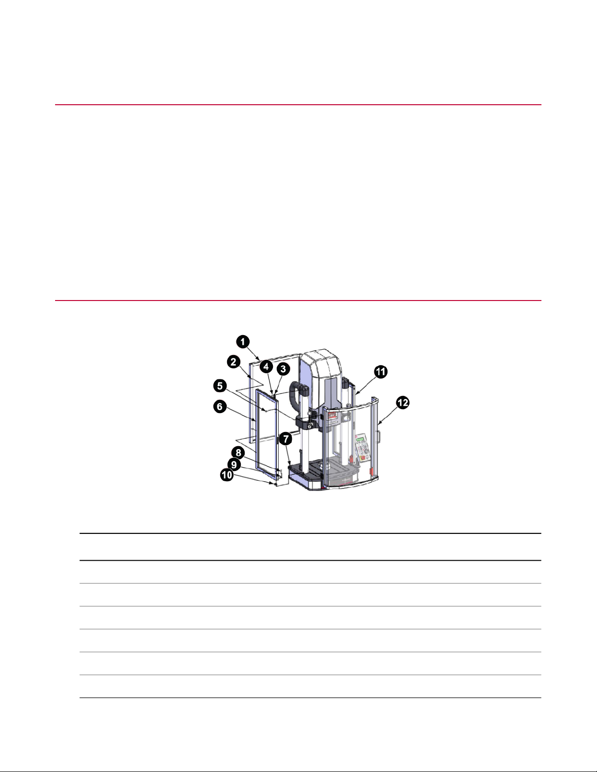
Install MTS Acumen Test Area Enclosure (Right-Hand Opening)
DescriptionItem
Rear panel assembly1
M6 x 1 mm x 35 mm socket low head screw2
Top bracket3
M6 x 1.00 mm x 12 mm buttonhead cap screw4
M6 x 25MM x 12 mm flathead screw5
Left side panel assembly6
6 MTS Acumen™ Electrodynamic Test System
Test Area Enclosure
Page 7

Test Area Enclosure Installation
DescriptionItem
Foot mount7
M5 X 35MM socket head screw, M5 butt fastener8
M5 C'Bore butt fastener9
Foot mount10
Right side panel assembly11
Front door assembly12
1. Raise the crosshead.
2. Put two foot mounts (items 7 and 10) on the frame in the provided machined indents.
3. Put a M6 x 1.00 mm x 12mm buttonhead cap screw (item 4) for the top bracket on the baseplate.
Once the side panel is in place and before you tighten down the bottom screws, it makes installation easier
to secure the top side panel bracket to the frame to help hold the side panel in position while you tighten
the bottom screws to secure the side pane to the frame base. This step puts the top bracket screw where
you can reach it when the time comes.
4. Put M5 C'Bore butt fasteners (item 9) in the two bottom slots in the side panel and insert the DIN912 M5
x 0.80 mm x 30 mm SST sockethead cap screws (item 8).
5. Position the side panel (item 6) on the frame such that the bottom screws fit through the foot mounts and
into the threaded holes.
6. Take the screw from step 3 and secure the top bracket (item 3) to the frame. Hand-tighten.
7. Hand-tighten the screws securing the side panel to the frame base.
8. Repeat steps 2 through 7 for the other side panel.
9. Using the supplied Allen wrench, snug down all fasteners. Do not over-tighten.
Fasteners should be tightened enough to hold the panels firmly in place but not so tight the panels cannot
be slightly positioned for alignment after the back panel (item 1) and front door (item 12) are installed.
10. Pre-install the door. There are (2) hinges. Mount both hinges to the door and torque to 8.8 [12 N] and then
place the door into position.
11. Place the front door into position with the handle to the right side, and secure the top hinge to the side
panel using one M6 x 1.00 mm x 12 mm buttonhead cap screw (item 5).
12. Close and latch the door to hold it in place.
13. Install the remaining three M6 x 25 mm x 12 mm flathead screws. Tighten enough to hold the door firmly
in place but not so tight the door cannot be slightly positioned for alignment after the back panel is installed.
MTS Acumen™ Electrodynamic Test System 7
Page 8

Test Area Enclosure Installation
14. It makes installation easier to route and secure the safety switch sensor cable prior to mounting the side
panel.
a) Place loop clamps over the sensor cable and position the clamps near the provided threaded mounting
holes.
b) If the safety switch is not pre-mounted, position the safety switch with the cable in a downward direction,
and the arrow-on switch pointing forward. Align the safety switch parallel and centered vertically. Using
an M4 x 25mm sockethead cap screw and M4 washer, mount the switch to side panel and torque to
0.57 N-m (5 lb-in.)
c) Loop the cable back along the bottom right edge. Loosely mount the cable to the bottom cross edge
with M4 x 8mm buttonhead cap screws. Slide the cable in the loop clamps to take up the slack. Torque
to 0.57 N-m (5 lb-in.)
d) Mount the side panel.
e) Prior to mounting the rear panel assembly, place the loop clamps onto the sensor cable at approximate
positions to the threaded mounting holes on back of the baseplate.
f) Loosely mount the cable to the baseplate. Slide the cable in the loop clamps to take up the slack.
Torque to 0.34 N-m (3 lb-in.)
8 MTS Acumen™ Electrodynamic Test System
Page 9

Test Area Enclosure Installation
g) Loop the cable down and back. Plug it into the enclosure switch connector.
In most cases where the test area enclosure is installed after frame installation, it will be necessary to
remove a jumper plug first. Do not discard the jumper plug. Keep the jumper plug in case the test area
enclosure is removed in the future. The machine requires either the jumper plug or the test area
enclosure to function.
15. Insert two M6 x 1 mm x 35 mm sockethead screws (item 2) through the top two holes of the back panel.
16. Position the back panel up against the two side panels such that the screws go into the threaded holes in
the side panels and hand-tighten.
17. Install the remaining two screws and tighten the four screws enough to hold the panel firmly in place, but
not so tight the panel cannot be slightly positioned for alignment.
18. If necessary, push the panels in place such that the tops are all aligned.
The door can be slightly adjusted. To adjust the door, loosen the screw that secures the side panel to the
top bracket, and pull or push the top of the side panel to raise or lower the handle side of the door so the
top of the door aligns with the side panel.
19. When the side panels, back panel, and door are all aligned, snug all fasteners according to the following
table.
Torque Guidelines
Torque toItem
11 N-m (8.2 lb-ft)A
10 N-m (7.3 lb-ft)B
12 N-m (8.8 lb-ft)C
6.5 N-m (4.8 lb-ft)D
MTS Acumen™ Electrodynamic Test System 9
Page 10

Test Area Enclosure Installation
20. Align the front door latch.
a) Loosen the top and bottom M4 flathead screws located inside the door latch vertical edge.
b) Adjust the latch so that the upper and lower catch ball bearings touch the latch simultaneously. You
can view this from the side.
c) Slightly tighten the two screws loosened in step 20a such that the latch is somewhat secure.
d) Close and open the door two or three times to allow the latch to align exactly with the catch ball bearings
on the side panel.
e) Fully tighten the two screws loosened in step 20a.
21. Remove the protective covering from the panels and door.
Install MTS Acumen Test Area Enclosure (Left-Hand Opening)
The test area enclosure is shipped configured with the right hand door opening (hinges on the left). If your layout
requires a left-hand door opening, you will first need to install the enclosure as shipped (steps 1 through 12) and
then change the door opening orientation (the remainder of this procedure).
10 MTS Acumen™ Electrodynamic Test System
Page 11

Test Area Enclosure Installation
Test Area Enclosure
DescriptionItem
Rear panel assembly1
M6 x 1 mm x 35 mm socket low head screw2
Top bracket3
M6 x 1.00 mm x 12 mm buttonhead cap screw4
M6 x 25MM x 12 mm flathead screw5
Left side panel assembly6
Foot mount7
M5 X 35MM socket head screw, M5 butt fastener8
M5 C'Bore butt fastener9
Foot mount10
Right side panel assembly11
Front door assembly12
1. Raise the crosshead.
2. Put two foot mounts (items 7 and 10) on the frame in the provided machined indents.
3. Put a M6 x 1.00 mm x 12mm buttonhead cap screw (item 4) for the top bracket on the baseplate.
Once the side panel is in place and before you tighten down the bottom screws, it makes installation easier
to secure the top side panel bracket to the frame to help hold the side panel in position while you tighten
the bottom screws to secure the side pane to the frame base. This step puts the top bracket screw where
you can reach it when the time comes.
MTS Acumen™ Electrodynamic Test System 11
Page 12

Test Area Enclosure Installation
4. Put M5 C'Bore butt fasteners (item 9) in the two bottom slots in the side panel and insert the DIN912 M5
x 0.80 mm x 30 mm SST sockethead cap screws (item 8).
5. Position the side panel (item 6) on the frame such that the bottom screws fit through the foot mounts and
into the threaded holes.
6. Take the screw from step 3 and secure the top bracket (item 3) to the frame. Hand-tighten.
7. Hand-tighten the screws securing the side panel to the frame base.
8. Repeat steps 2 through 7 for the other side panel.
9. Using the supplied Allen wrench, snug down all fasteners. Do not over-tighten.
Fasteners should be tightened enough to hold the panels firmly in place but not so tight the panels cannot
be slightly positioned for alignment after the back panel (item 1) and front door (item 12) are installed.
10. Place the front door into position and secure the top hinge to the side panel using one M6 x 1.00 mm x
12 mm buttonhead cap screw (item 5).
11. Close and latch the door to hold it in place.
12. Install the remaining three M6 x 1.00 mm x 12 mm buttonhead cap screws. Tighten enough to hold the
door firmly in place, but not so tight the door cannot be slightly positioned for alignment after the back
panel is installed.
13. Remove the four (4) M6 buttonhead cap screws and washers (items 1 and 2) and safety switch (item 3)
from the door assembly and right side panel and set aside.
14. With the door lightly secured to the left side panel, remove four (4) M6 flathead screws (item 4) that are
securing the upper and lower hinges to the left side panel assembly. Remove the door assembly and set
aside.
15. Remove the two (2) M3 buttonhead screws (item 5) and two (2) bumpers (item 6) from the right side panel
assembly.
16. Remount the bumpers to the left side panel assembly.
17. Remove two (2) M4 flathead screws (item 7) and tension catch (item 8) from the right side panel assembly
and remount in the left side panel assembly.
18. Rotate the door assembly 180 degrees and remount to the right side panel assembly.
19. Remount the safety switch (item 3) to the left side panel assembly with the sensor cable in an upward
direction.
12 MTS Acumen™ Electrodynamic Test System
Page 13

20. Route and secure the safety switch sensor cable.
Test Area Enclosure Installation
MTS Acumen™ Electrodynamic Test System 13
Page 14

Test Area Enclosure Installation
a) Place the loop clamps onto the sensor cable, and position the clamps near the provided threaded
mounting holes on the vertical side edge and bottom left cross edge.
b) Position the safety switch with the cable in an upward direction and the arrow-on switch pointing forward.
Align the safety switch parallel and centered to vertical edge. Using the M4 x 25mm lg socket head
cap screw and M4 washer, mount the switch to the side panel and torque to 0.57 N-m (5 lb-in.)
c) Loop the cable down and loosely mount to the vertical edge with the M4 x 8mm lg buttonhead cap
screw.
d) Slide the cable in the loop clamps to take up slack. Torque M4 buttonhead cap screws to 0.34 N-m (3
lb-in.)
e) Loop the cable back along the left cross edge. Loosely mount the cable to the bottom cross edge with
M4 buttonhead cap screws.
f) Repeat step d.
g) Mount the side panel per test area enclosure installation instructions.
h) Prior to mounting the rear door panel, place the loop clamps onto the sensor cable at approximate
positions to the threaded mounting holes nearest to the left side panel on the back of the baseplate.
i) Loosely mount the cable to the baseplate. Repeat step d.
j) Loop the cable down and plug into the enclosure switch connector.
In most cases where the test area enclosure is installed after frame installation, it will be necessary to
remove a jumper plug first. Do not discard the jumper plug. Keep the jumper plug in case the test area
enclosure is removed in the future. The machine requires either the jumper plug or the test area enclosure
to function.
21. Insert two M6 x 1 mm x 35 mm socket head screws (item 2) through the top two holes in the back panel.
22. Position the back panel up against the two side panels such that the screws go into the threaded holes in
the side panels and hand-tighten.
23. Install the remaining two screws and tighten the four screws enough to hold the panel firmly in place, but
not so tight the panel cannot be slightly positioned for alignment.
24. If necessary, push the panels in place such that the tops are all aligned.
The door can be slightly adjusted. To adjust the door, loosen the screw that secures the side panel to the
top bracket, and pull or push the top of the side panel to raise or lower the handle side of the door so the
top of the door aligns with the side panel.
25. When the side panels, back panel, and door are all aligned, snug all fasteners according to the following
table.
14 MTS Acumen™ Electrodynamic Test System
Page 15

Test Area Enclosure Installation
26. Align the front door latch.
Torque Guidelines
Torque toItem
11 N-m (8.2 lb-ft)A
10 N-m (7.3 lb-ft)B
12 N-m (8.8 lb-ft)C
6.5 N-m (4.8 lb-ft)D
MTS Acumen™ Electrodynamic Test System 15
Page 16

Test Area Enclosure Installation
a) Loosen the top and bottom M4 flathead screws located inside the door latch vertical edge.
b) Adjust the latch so that the upper and lower catch ball bearings touch the latch simultaneously. You
can view this from the side.
c) Slightly tighten the two screws loosened in step 20a such that the latch is somewhat secure.
d) Close and open the door two or three times to allow the latch to align exactly with the catch ball bearings
on the side panel.
e) Fully tighten the two screws loosened in step 20a.
27. Remove the protective covering from the panels and door.
16 MTS Acumen™ Electrodynamic Test System
Page 17

100-265-243 A
Page 18

 Loading...