


1997
SPLIT-TYPE, HEAT PUMP AIR CONDITIONERS
No. OC122
REVISED EDITION-A
TECHNICAL & SERVICE MANUAL
Series PCFY Ceiling Suspended
<Indoor unit>
Models PCFY-40VGM
PCFY-63VGM
PCFY-100VGM
PCFY-125VGM
|
CONTENTS |
||
|
1. |
FEATURES ···········································2 |
|
|
2. PART NAMES AND FUNCTIONS ········4 |
||
|
3. |
SPECIFICATION···································6 |
|
|
4. OUTLINES AND DIMENSIONS············8 |
||
|
5. |
WIRING DIAGRAM·····························12 |
|
|
6. REFRIGERANT SYSTEM DIAGRAM ···13 |
||
|
7. TROUBLE SHOOTING·······················14 |
||
INDOOR UNIT |
8. DISASSEMBLY PROCEDURE···········19 |
||
9. |
PARTS LIST········································23 |
||
|
|||
Revision
•Parts List has been partially modified.
•Please destroy OC122.

1 
 FEATURES
Series PCFY Ceiling Suspended
Indoor unit
Models |
Cooling capacity / Heating capacity |
||
|
|
||
W |
Kcal/h |
||
|
|||
PCFY-40VGM |
4,700/5,200 |
4,000/4,500 |
|
PCFY-63VGM |
7,300/8,300 |
6,300/7,100 |
|
PCFY-100VGM |
11,600/13,000 |
10,000/11,200 |
|
PCFY-125VGM |
14,500/16,300 |
12,500/14,000 |
|
|
|
|
|
1. AIR OUTLET
New PCFY series models have 1 air outlet (auto vane switching of horizontal air flow / down flow by switched by auto vane) instead of 2 (horizontal, and down frows).
|
|
|
|
Protruding portion A |
|
2. EASY TO CLEAN ; FLOCKLESS VANE |
|
|
|
Unifies the air speed |
|
|
B |
with the vane. |
|||
With our original air current control mechanism, a flockless vane is |
|
|
|
+ |
|
|
|
|
Protruding portion B |
||
newly adapted. |
Flockless vane |
||||
Sending the air to the upper |
|||||
The flockless vane prevents the condensation on the vane. |
|
|
|
||
|
|
A |
area of the vane |
||
By changing the vane to the flockless type, the unit can be cleaned |
|
|
= |
||
|
|
|
|||
much easier with mild household detergent. |
|
|
|
Prevents the air comes from |
|
|
Air outlet |
||||
|
outside the unit |
||||
|
|
|
|
||
3. NEW MATERIALS FOR BETTER OIL RESISTANCE
We have changed the materials of grill, filer, fan and fan casing from ABS to P.P. (polypropylene) for better oil resistance. As a result, oil crazing is cut in half.
2

4. SIMPLIFIED INSTALLATION WORK (DIRECT SUSPENDING METHOD)
Simplified the installation work by changing the suspending method to the direct suspending method (suspending the unit directly from the suspension fixture).
In this way, the unit can be attached to the suspension fixture without removing the installation parts off (Only the side cover is removed). This method is much simpler than the ¨One-time installation method¨.
5. IMPROVING EFFICIENCY OF PIPING WORK
1 Removed the knockout work by separating the piping space from the air outlet for efficiency of the piping work.
2 Improved the flexibility by making it possible for drainage pipe to exit not only from the right side back but also from the left side back.
Back panel |
Side panel |
|
G L
L Open G
D Open
U-cut
D
L : Liquid pipe
G: Gas pipe
D: Drain pipe
Drain pan |
Rubber plug |
Insulation cover Joint coupliy 
 (attached) (attached)
Insulation |
|
Drain pipe |
cover |
Band |
(purchased locally) |
|
(attached) |
|
Knockout work is needed for the top part. When optional drain-up machine is installed, the refrigerant pipe exits out from the top.
Please move the rubber plug for the unit to the right joint when drainage pipe exits from the left side.
6.ADVANCED MICROPROCESSOR [PAR-F25MA]
(1)Easy to use microprocessor 1)Ultra-thin remote controller
The streamlinde,square controller is designed to blend well with any interior.Also,the sophisticated microproceeor allows you to easily carry out a wide range of operations.
2)Attractive liquid crystal display(LCD)
The unit´s operation mode,set temperature,room temperature,timer setting,fan speed,louver oper-ation,and air flow direction are displayed on the remote controller´s easy-to-read Liquid Crystal Dis-play(LCD).
3)Convenient 24-hour ON-OFF timer
The timer switches Mr.SLIM on and off automati-cally at the time you set. Once the timer is set,the remaining time is shown on the LCD.
3

2 
 PART NAMES AND FUNCTION
● Indoor (Main) Unit
Left/right guide vanes
Air outlet
Change the direction of airflow from the horizontal blower.
Long-life fillter
Removes dust and foreigh matter from air coming in through the grille (Recommended cleaning interval : Approx, every 2,500 operating hours)
Up/down guide vanes |
Air intake |
|
Intake grille |
Change the direction of airflow from the vartical blower.
● Remote controller |
[PAR-F25MA] |
|
|
|
● Once the controls are set, the same operation mode can |
||
|
be repeated by simply pressing the ON/OFF button. |
||
● Operation buttons |
|
|
|
TIMER button |
TIME SETTING button |
AIR SPEED button |
|
This switches between continuous |
This sets of switches the current time. |
This sets the ventilation fan speed. |
|
operation and the timer operation. |
start time and stop time. |
|
|
|
|
||
OPERATION SWITCH button |
|
|
ON/OFF button |
Press this button to switch the cooler |
|
|
This swiches between the operation |
electronic dry (dehumidify) automatic and |
|
|
and stop modes each time it is |
heater modes. |
|
|
pressed. The lamp on this button |
|
|
|
lights during operation. |
|
|
|
AIR DIRECTION button |
TEMP ADJUSTMENT button |
|
|
This adjusts the vertical angle of the |
|
|
ventilation. |
|
This sets the room temparature The |
|
|
|
temparature setting can be performed in 1°C |
|
|
FILTER button |
units |
|
|
|
Setting range |
|
|
This resets the filter service indication |
Cooler 19°C to 30°C |
|
|
display. |
LOUVER button |
CHECK-TEST RUN button |
||
This switches the horizontal fan |
Only press this button to perform an |
||
motion ON and OFF. |
inspection check or test operation Do |
||
(This button does not operate in this |
not use it for nomal operation. |
||
|
|
||
model) |
|
|
|
4

● Display
CENTRALLY CONTROLLED display
This indicates when the unit is controlled by optional features such as central control type remote controller.
TIMER display
This indicates when the continous operation and time operation modes are set.
It also display the time for the timer operation at the same time as when it is set.
OPERATION MODE display
This indicates the operation mode.
STANDBY display
This indicates when the standby mode is set from the time the sleep operation starts until the heating air is discharged.
DEFROST display
This indicates when the defrost operation is performed.
CLOCK display |
In this display example on the |
|
bottom left, a condition where all |
||
|
||
The current time , start time and stop |
display lamps light is shown for |
|
time can be displayed in tensecond |
explanation purposes although this |
|
intervals by pressing the time switch |
differs from actual operation. |
|
button. The start time or stop time is |
||
|
||
always displayed during the timer |
|
|
operation. |
|
|
|
AIR DIRECTION display |
|
|
The selected fan speed is displayed. |
|
|
FAN SPEED display |
|
|
This displays the air direction. |
|
|
ROOM TEMPERATURE display |
|
|
The temperature of the suction air is |
|
|
displayed during operation. The |
|
|
display range is 8° to 39°C. The |
|
|
display flashes 8°C when the actual |
|
|
temperature is less than 8° and |
|
|
flashes 39°C when the actual |
|
|
temperature is greater than 39°C. |
|
|
Operation lamp |
|
4 |
This lamp lights during operation, |
|
|
goes off when the unit stops and |
|
|
flashes when amalfunction occurs. |
|
|
CHECK MODE |
|
|
display |
|
|
TEST RUN |
|
|
This display lights in the check mode |
|
|
or when a test operation is |
|
|
performed. |
CHECK display |
|
|
|
|
This indicates when a malfunction |
|
SET TEMPERATURE display |
|
POWER display |
|
|
|
|
|
has occurred in the unit which should |
|
This displays the selected setting |
|
This lamp lights when electricity is |
be checked. |
|
|
||
|
temperature. |
|
supplied to the unit. |
|
|
|
|
||
|
|
|
|
|
Caution
FILTER display
This lamp lights when the filter need to be cleaned.
●Only the Power display lights when the unit is stopped and power supplied to the unit.
●When power is turned ON for the first time the (CENTRAL CTRL) display appears to go off momentarily but this is not a malfunction.
●When the central control remote control unit, which is sold separately, is used the ON-OFF button, operation switch button and  TEMP adjustment button do not operate.
●“NOT AVAILABLE” is displayed when the Air speed button are pressed.This indicates that this room unit is not equipped
with the fan direction adjustment function and the louver function.
●When power is turned ON for the first time, it is normal that “HO” is displayed on room temperature indecation (For max.2minutes). Please wait until this “HO” indication disappear then start the operation.
5

3 
 SPECIFICATIONS
3-1. Specification
Item
|
Power |
V•Hz |
||
Cooling capacity |
kW |
|||
Heating capacity |
kW |
|||
charocteristic |
Power |
Cooling |
kw |
|
|
|
|||
|
|
|
||
|
supply Heating |
kW |
||
|
Startin Cooling |
A |
||
|
g |
|
A |
|
Electric |
current Heating |
|||
factor |
Heating |
% |
||
|
Power |
Cooling |
% |
|
|
|
|
||
|
Exteior |
– |
||
(munsell symbol) |
||||
|
||||
|
|
Height |
mm |
|
Outdimensions |
Width |
mm |
||
|
|
Depth |
mm |
|
Heat exchanger |
- |
|||
|
Fan No |
- |
||
F |
Air flow #3 |
k/min |
||
a |
External |
Pa |
||
n |
||||
static pressure |
||||
|
Fan motor |
kW |
||
|
Output |
|||
|
|
|||
|
Insulator |
|
||
Air filter
|
Gas |
[mm |
Pipe |
side |
|
dimensions |
Liquid |
[mm |
|
side |
|
Drain pipe size |
[mm |
|
Noise level |
dB(A) |
|
Product weight |
kg |
|
PCFY-40VGM |
|
PCFY-63VGM |
|
PCFY-100VGM |
|
PCFY-125VGM |
|
|
|
|
|
|
|
|
|
Single phase 220V-240V 50 HZ |
|
|
||
4.7 |
|
7.3 |
|
|
14.5 |
|
|
|
11.6 |
|
|||
5.2 |
|
8.3 |
|
13.0 |
|
14.5 |
0.10 |
|
0.13 |
|
0.16 |
|
0.24 |
0.10 |
|
0.13 |
|
0.16 |
|
0.24 |
0.43 |
|
0.55 |
|
0.70 |
|
1.06 |
0.43 |
|
0.55 |
|
0.70 |
|
1.06 |
92 |
|
93 |
|
92 |
|
92 |
92 |
|
93 |
|
92 |
|
92 |
|
|
Unit : Munsell<0.70Y 8.59/0.97> |
|
|
||
210 |
|
|
|
270 |
||
|
|
|
||||
1000 |
|
1310 |
|
1310 |
|
|
|
|
|
1620 |
|||
|
|
|
|
|
|
|
|
|
|
680 |
|
|
|
|
|
|
crosfin |
|
|
|
|
|
|
|
|
|
|
Sirocco fan 2 |
|
Sirocco fan 3 |
|
Sirocco fan 3 |
|
Sirocco fan 4 |
12-11-10-8 |
|
18-16-14-12 |
|
25-23-20-18 |
|
35-32-28-26 |
|
|
|
|
|
|
|
|
|
|
0 |
|
|
|
0.054 |
|
0.07 |
|
|
||
|
|
0.09 |
|
0.15 |
||
|
|
|
|
|
|
|
|
|
Polyethylene sheet |
|
|
||
|
|
PP honey comb |
|
|
||
|
|
|
|
|||
12.7<1/2”> |
|
15.88<5/8”> |
|
19.05<3/4”> |
||
6.35<1/4”> |
|
9.52<3/8”> |
|
9.52<3/8”> |
||
|
|
PVC pipe VP-25 connectable |
|
|
||
38-36-33-29 |
|
39-37-34-32 |
|
|
||
|
|
43-41-38-36 |
|
44-42-39-37 |
||
27 |
|
34 |
|
37 |
|
43 |
|
|
|
|
|
|
|
Note 1. |
Rating conditions(JIS B 8616) |
||
|
Cooling: |
Indoor: |
27°C DB. 19.5°C WB |
|
|
outdoor: |
35°C DB. 24°C WB |
|
Heating: |
Indoor: |
21°C |
|
|
outdoor: |
7°C DB. 6°C WB |
Note 2. |
Air flow and the noise level are indicated as High-Middium 1-Middium 2-Low. |
||
6

3-2. Electrical parts specifications
Parts |
Model |
Symbol |
PCFY-40VGM |
PCFY-63VGM |
PCFY-100VGM |
PCFY-125VGM |
name |
|
|
|
|
|
|
Tranrsformer |
|
T |
|
(Primary) 50/60Hz 220-240V (Secondary) (18.4V 1.7A) |
||
Room temperature |
|
|
|
|
|
|
thermistor |
|
TH21 |
Resistance: 0:/15k',10:/9.6k',20:/6.3k',25:/5.4k',30:/4.3k',40:/3.0k' |
|||
Liquid pipe |
|
|
|
|
|
|
thermistor |
|
TH22 |
Resistance: 0:/15k',10:/9.6k',20:/6.3k',25:/5.4k',30:/4.3k',40:/3.0k' |
|||
Gas pipe |
|
|
|
|
|
|
Thermistor |
|
TH23 |
Resistance: 0:/15k',10:/9.6k',20:/6.3k',25:/5.4k',30:/4.3k',40:/3.0k' |
|||
Fuse |
|
FUSE |
|
250V 6.3A |
|
|
(Indoor controller board) |
|
|
|
|
|
|
Fan motor |
|
MF1,2 |
4-Pole OUTPUT 54W 4-Pole Output 70W |
4-Pole Output 90W |
4-Pole Output 150W |
|
(with Inner-thermostat) |
|
D09B4P54MS |
D09B4P70MS |
D10B4P90MS |
D10B4P150MS |
|
|
|
|
Inner-thermostat |
OFF 130:±5: |
|
|
Fan motor capacitor |
C1 |
3uF x 440V |
4uF x 440V |
4uF x 440V |
6uF x 440V |
|
Vane motor |
|
MV |
MP35EA |
MP35EA |
MP42EA |
|
|
DC12V |
DC12V |
DC12V |
|||
|
|
|
||||
|
|
|
DC12V Stepping motor |
|
DC12V Stepping motor drive |
|
Linear expansion valve |
LEV |
drive |
|
{ 5.2 (0~2000pulse) |
|
|
{ 3.2 (0~2000pulse) |
|
|
||||
|
|
|
|
EDM-804ME |
|
|
|
|
|
EDM-402ME |
|
|
|
Power supply |
|
|
|
|
|
|
terminal block |
|
TB2 |
|
(L,N,;) 330V 30A |
|
|
Transmission |
|
|
|
|
|
|
terminal block |
|
TB5 |
|
(M1,M2,S) 330V 30A |
|
|
7

8 |
|
|
|
|
|
5 Refrigerant-pipe connection (liquid pipe side/flared connection) |
|
|
|
|
|
40VGM-PCFY |
UNITINDOOR |
||||
1 Drainage pipe connection (26mm I.D.) |
|
|
|
|
|
|
|
|
|
||||||||
2 Drainage pipe connection (for the left arrangement) |
|
6 Knock out hole for upper drain pipe arrangement |
|
|
|
|
|
|
|
|
|||||||
3 Knock out hole for left drain-piping arrangement |
|
7 Knock out hole for left drain pipe arrangement |
|
|
|
|
|
|
|
|
|
||||||
4 Refrigerant-pipe connection (gas pipe side/flared connection) |
8 Knock out hole for wining arrangement |
|
|
|
|
|
|
|
|
|
|||||||
|
|
|
|
|
|
|
|
|
|
NOTES: |
|
|
|
|
|
|
|
|
|
|
|
|
|
|
|
|
|
1. Use M10 or W3/8 screws for anchor bolt. |
|
|
|
||||
|
|
|
|
|
|
|
|
|
|
2. Please be sure when installing the drain-up machine (option parts). |
|
|
|||||
|
|
|
|
|
|
|
|
|
|
refrigerant pipe will be only upper drain pipe arrangement. |
|
|
|
||||
|
|
|
|
|
|
|
|
ceiling |
|
|
6 |
|
|
|
|
|
|
|
2 |
Electrical box [FRONT VIEW] |
5 |
1 4 |
|
17 |
|
|
|
|
|
|
|
||||
|
|
|
|
|
|
|
|
|
|
|
|||||||
3 |
|
32 |
|
8 |
|
Gapto |
|
150 |
|
80 |
|
|
|
|
|
||
|
|
|
|
1 |
|
|
|
|
|
|
|
||||||
|
|
|
Celling |
|
|
|
|
|
|
|
|
|
|
|
|
|
|
179 |
|
161 |
|
3879 |
|
131 |
175 |
|
|
140 |
70 |
320 |
|
|
|
|
|
|
|
|
|
|
|
|
|
|
|
|
|
|
|
|
|
||
42 |
|
|
|
38 |
86 |
|
46 |
|
|
|
|
|
|
|
|
|
|
6-7 |
|
|
|
|
|
|
|
|
|
|
|
|
|
|
|
|
|
|
|
|
|
138 |
|
|
|
|
|
|
|
|
|
|
|
|
|
|
|
|
|
|
|
|
|
|
|
|
|
|
|
|
|
|
|
|
|
|
|
|
171 |
|
|
|
|
|
|
|
|
|
|
|
|
When electrical |
|
|
|
|
263 |
|
|
|
|
|
|
|
|
|
|
|
|
|
|
525 |
|
352 |
|
|
|
|
|
|
|
|
|
|
|
|
|
box is pulled |
|
|
|
|
|
933 (suspension bolt pitch) |
|
|
|
|
|
|
|
||||
|
|
928 |
|
|
|
|
|
|
|
85 |
|
|
|
||||
down |
|
|
|
|
|
|
|
|
|
|
|
|
|
|
|
||
|
|
|
|
|
|
|
|
983 |
|
|
|
|
|
|
|
||
|
|
Electrical box 70 |
|
|
|
|
|
|
|
|
|
15 |
|
|
|
||
|
|
|
|
|
|
|
|
|
|
|
|
|
|
|
|
||
|
|
|
|
|
|
|
|
|
|
|
81 |
180 |
210 |
157 |
|
|
|
|
|
|
1 |
|
|
|
|
|
|
|
76 |
|
|
|
|
|
|
|
|
|
|
|
|
|
|
|
|
|
|
|
|
|
|
|
|
|
|
|
|
226 |
2 |
|
|
Air outlet |
904 |
|
|
|
|
182 |
(3/8F) liquid |
|
|
|
|
|
|
|
|
|
|
|
|
|
|
|
|||||
|
|
|
|
|
|
|
|
|
|
|
|
|
|
|
|
|
|
1000 |
201 |
(5/8F) gas |
|
241 |
(Drainage) |
|
680 |
|
|
254 |
|
Air intake |
|
|
918 |
|
|
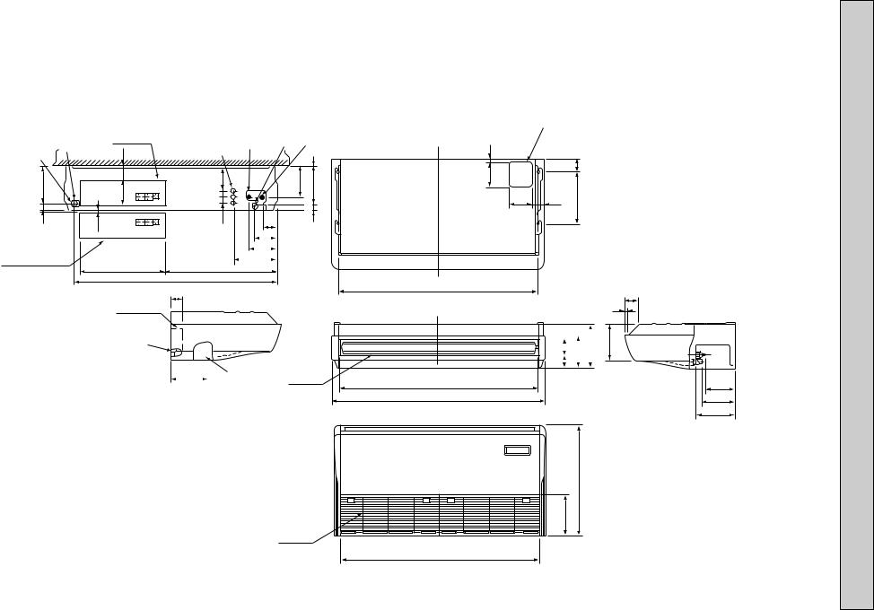
DIMENSIONS AND OUTLINES 4

1 Drainage pipe connection (26mm I.D.) |
5 Refrigerant-pipe connection (liquid pipe side/flared connection) |
2 Drainage pipe connection (for the left arrangement) |
6 Knock out hole for upper drain pipe arrangement |
3 Knock out hole for left drain-piping arrangement |
7 Knock out hole for left drain pipe arrangement |
4 Refrigerant-pipe connection (gas pipe side/flared connection) |
8 Knock out hole for wining arrangement |
NOTES:
1. Use M10 or W3/8 screws for anchor bolt.
2. Please be sure when installing the drain-up machine (option parts). refrigerant pipe will be only upper drain pipe arrangement.
2 |
|
Electnical box |
[ FRONT VIEW ] |
5 |
1 4 |
ceiling |
|
|
|
|
to |
||||
3 |
|
|
8 |
|
|
|
|
|
32 |
|
|
1 |
Gap |
||
|
|
Celling |
|
|
|||
|
|
|
|
|
|
|
|
179 |
|
161 |
3879 |
|
131 |
175 |
|
42 |
6~7 |
|
38 |
86 |
|
46 |
|
|
|
|
|
|
|
|
|
|
|
|
|
138 |
|
|
|
|
|
|
|
171 |
|
|
|
|
|
|
|
263 |
|
|
|
When electrical |
|
525 |
416 |
|
|
|
|
box is pulled |
|
|
1235 |
|
|
|
|
down |
|
|
|
|
|
|
|
|
|
|
|
|
|
|
|
Electrical box |
70 |
|
|
|
|
|
|
|
1
Air outlet
226 2
Air intake
150 17
140
1240 (suspension bolt pitch)
1290
1214
1310
1228
6
|
80 |
|
|
|
|
|
|
|
70 |
320 |
|
|
||
|
|
|
|
|
|
|
|
|
85
15
|
|
|
|
|
|
|
|
|
|
157 |
|
|
|
76 |
|
180 |
210 |
|
|||||||
|
|
|
81 |
|
|
|
|
|
||||
|
|
|
|
|
|
|
|
|
||||
|
|
|
|
|
|
|
|
|
|
|||
|
|
|
|
|
|
|
|
|
|
|
|
|
|
|
|
|
|
|
|
|
|
|
|
|
|
|
|
|
|
|
|
|
|
|
|
|
|
|
|
|
|
|
|
|
|
|
|
|
|
|
|
680
254
182 (3/8F liquid)
201 (5/8F gas)
241 (Drainage)
63VGM-PCFY
9
10
1 Drainage pipe connection (26mm I.D.) |
5 Refrigerant-pipe connection (liquid pipe side/flared connection) |
||
2 Drainage pipe connection (for the left arrangement) |
6 Knock out hole for upper drain pipe arrangement |
|
|
3 Knock out hole for left drain-piping arrangement |
7 Knock out hole for left drain pipe arrangement |
NOTES: |
|
4 Refrigerant-pipe connection (gas pipe side/flared connection) |
8 Knock out hole for wining arrangement |
||
1. Use M10 or W3/8 screws for anchor bolt. |
|||
|
|
||
2. Please be sure when installing the drain-up machine (option parts). refrigerant pipe will be only upper drain pipe arrangement.
|
|
Electnical box |
[ FRONT VIEW ] |
|
1 |
4 |
ceiling |
|
|
2 |
5 |
to |
|||||
|
93 |
|
8 |
|
|
|||
3 |
|
Celling |
|
|
1 |
Gap |
||
239 |
|
160 |
|
38 140 |
|
192 |
236 |
|
42 |
|
6~7 |
|
38 |
|
|
45 |
|
|
|
|
|
86 |
|
|
||
|
|
|
|
|
|
|
|
|
|
|
|
|
|
|
138 |
|
|
When electrical |
|
171 |
|||
box is pulled |
|
|
|
|
|
263 |
|||||
down |
|||||
525 |
687 |
|
|
|
|
1235
70
Electrical box
1
|
|
|
|
|
|
|
|
|
229 |
|
|
|
2 |
Air outlet |
|||
|
|
|
|
|
|
|
|
|
|
|
|
|
|
|
|
|
|
Air intake
|
6 |
|
17 |
|
|
150 |
|
80 |
140 |
70 |
320 |
|
1240 (suspension bolt pitch)
87 16
|
|
|
|
|
|
|
|
217 |
|
|
|
|
|
|
270 |
||
|
96 |
|
207 |
|
||||
|
|
|
||||||
|
81 |
|
|
|
|
|
||
|
|
|
|
|
|
|
|
|
1214
1310
680
254
1228
182 (3/8F liquid)
198 (5/8F gas)
245 (Drainage)
100VGM-PCFY
1 Drainage pipe connection (26mm I.D.) |
5 Refrigerant-pipe connection (liquid pipe side/flared connection) |
2 Drainage pipe connection (for the left arrangement) |
6 Knock out hole for upper drain pipe arrangement |
3 Knock out hole for left drain-piping arrangement |
7 Knock out hole for left drain pipe arrangement |
4 Refrigerant-pipe connection (gas pipe side/flared connection) |
8 Knock out hole for wining arrangement |
NOTES:
1. Use M10 or W3/8 screws for anchor bolt.
2. Please be sure when installing the drain-up machine (option parts). refrigerant pipe will be only upper drain pipe arrangement.
2 |
3 |
239 |
42 |
When electrical box is pulled down
Electrical box |
|
[ FRONT VIEW ] |
|
5 |
1 |
4 |
ceiling |
|
8 |
Gapto |
|||||
|
93 |
Celling |
|
1 |
|||
|
|
|
|
||||
|
|
|
|
|
|
|
|
|
160 |
|
38 140 |
|
192 |
236 |
|
6~7 |
|
|
38 |
|
|
45 |
|
|
|
|
86 |
|
|
||
|
|
|
|
|
|
|
|
|
|
|
|
|
138 |
|
|
|
|
|
|
|
171 |
|
|
263
525 |
687 |
1545
70
Electrical box
1
|
|
|
|
|
|
|
|
Air outlet |
229 |
|
|
|
2 |
||||
|
|
|
|
|||||
|
|
|
|
|
|
|
|
|
Air intake
|
6 |
|
18 |
|
|
150 |
|
80 |
140 |
70 |
320 |
|
1547(suspension bolt pitch)
87
16
81 96 |
207 |
270 |
217 |
1524 |
|
|
182 |
1620 |
|
|
198 |
|
|
|
245 |
|
680 |
|
|
254 |
1535
125VGM-PCFY
(3/8F liquid)
(3/4F gas)
(Drainage)
11
 Loading...