


 Loading...
 SAFETY PRECAUTIONS
(Always read these instructions before using this equipment.)
Before using this product, please read this manual and the relevant manuals introduced in this manual carefully and pay full attention to safety to handle the product correctly.
The instructions given in this manual are concerned with this product. For the safety instructions of the programmable controller system, please read the CPU module user's manual.
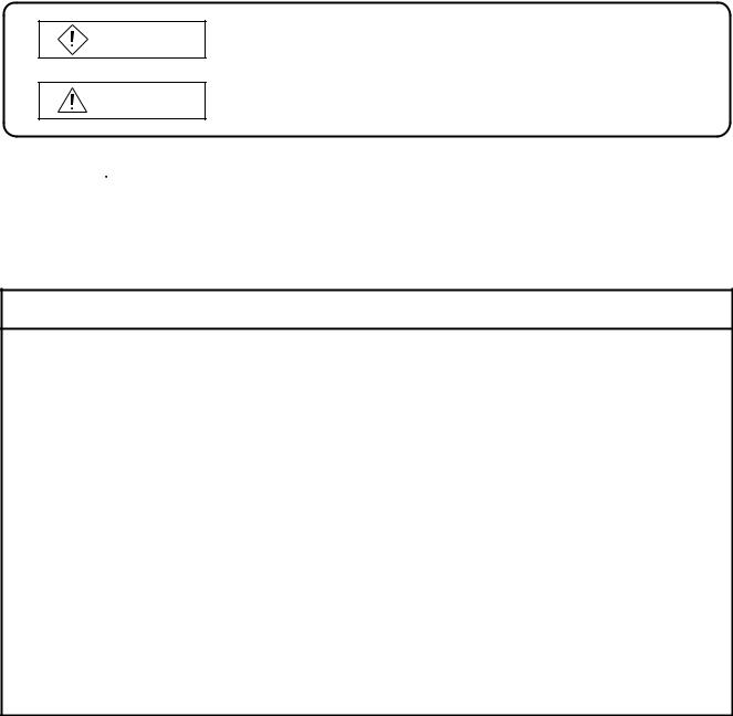
In this manual, the safety instructions are ranked as "DANGER" and "CAUTION".
DANGER
Indicates that incorrect handling may cause hazardous conditions, resulting in death or severe injury.
CAUTION
Indicates that incorrect handling may cause hazardous conditions, resulting in medium or slight personal injury or physical damage.
Note that the  CAUTION level may lead to a serious consequence according to the circumstances. Always follow the instructions of both levels because they are important to personal safety.
Please save this manual to make it accessible when required and always forward it to the end user.
[Design Precautions]
 DANGER
 Depending on the GOT main unit, communication board, communication module or cable fault, the output from the GOT interface module may remain ON or may remain OFF.
An external monitoring circuit should be provided to check for output signals which may lead to a serious accident.
Not doing so can cause an accident due to false output or malfunction.
 If a communication fault (including cable disconnection) occurs during monitoring on the GOT, communication between the GOT and PLC CPU is suspended and the GOT becomes inoperative.
For bus connection |
: The CPU becomes faulty and the GOT inoperative. |
For other than bus connection |
: The GOT becomes inoperative. |
A system where the GOT is used should be configured to perform any significant operation to the system by using the switches of a device other than the GOT on the assumption that a GOT communication fault will occur.
Not doing so can cause an accident due to false output or malfunction.
 Do not use the GOT as the warning device that may cause a serious accident.
An independent and redundant hardware or mechanical interlock is required to configure the device that displays and outputs serious warning.
Failure to observe this instruction may result in an accident due to incorrect output or malfunction.
A - 1

[Design Precautions]
 DANGER
 Incorrect operation of the touch switch(s) may lead to a serious accident if the GOT backlight is gone out.
When the GOT backlight goes out, the display section turns black and causes the monitor screen to appear blank, while the input of the touch switch(s) still remains active.
This may confuse an operator in thinking that the GOT is in “screensaver” mode, who then tries to release the GOT from this mode by touching the display section, which may cause a touch switch to operate.
Note that the following occurs on the GOT when the backlight goes out. The monitor screen disappears even when the screensaver is not set.
The monitor screen will not come back on by touching the display section, even if the screensaver is set.
 CAUTION
 Do not bundle the control and communication cables with main-circuit, power or other wiring. Run the above cables separately from such wiring and keep them a minimum of 100mm apart. Not doing so noise can cause a malfunction.
[Mounting Precautions]
 DANGER
 Before installing or removing the GOT main unit to or from an enclosure, always turn the GOT power OFF before installing or removing the GOT main unit to or from an enclosure.
Not doing so can cause a module failure or malfunction.
 Before loading or unloading the communication board, communication module, external I/O interface module or memory card interface module to or from the GOT, always turn the GOT power OFF before loading or unloading the communication board, communication module, external I/O interface module or memory card interface module to or from the GOT.
Not doing so can cause a module failure or malfunction.
 CAUTION
 The GOT should be used in the environment given in the general specifications of this user's manual.
Not doing so can cause an electric shock, fire, malfunction or product damage or deterioration.  When mounting the GOT main unit to an enclosure, tighten the mounting screws in the specified
torque range.
Undertightening can cause a drop, short circuit or malfunction.
Overtightening can cause a drop, short circuit or malfunction due to the damage of the screws or module.
A - 2

[Mounting Precautions]
 CAUTION
 When loading the communication board, External I/O interface module or communication module to the GOT main unit, fit it to the connection interface of the GOT and tighten the mounting screws in the specified torque range.
Undertightening can cause a drop, failure or malfunction.
Overtightening can cause a drop, failure or malfunction due to the damage of the screws or module.
 When loading the communication board to the GOT main unit, take care not to become injured by the components that are installed or surrounding materials.
 When loading the communication board to the GOT main unit, remove any static electricity accumulated on your body before engaging in work.
Otherwise, this may result in damage to the board.
[Wiring Precautions]
 DANGER
 Before starting wiring, always turn the GOT power OFF before starting wiring. Not doing so may cause an electric shock, product damage or malfunction.
 CAUTION
 Please make sure to ground FG terminal of the GOT power supply unit by applying Class D Grounding (Class 3 Grounding Method) or higher which is used exclusively for the GOT.
Not doing so may cause an electric shock or malfunction.
 Correctly wire the power supply module on the GOT after confirming the rated voltage and terminal arrangement of the product.
Not doing so can cause a fire or failure.
 Tighten the terminal screws of the GOT power supply section in the specified torque range. Undertightening can cause a short circuit or malfunction.
Overtightening can cause a short circuit or malfunction due to the damage of the screws or module.
 Exercise care to avoid foreign matter such as chips and wire offcuts entering the module. Not doing so can cause a fire, failure or malfunction.
 Plug the bus connection cable by inserting it into the connector of the connected module until it "clicks".
After plugging, check that it has been inserted snugly.
Not doing so can cause a malfunction due to a contact fault.
 Plug the communication cable into the connector of the connected module and tighten the mounting and terminal screws in the specified torque range.
Undertightening can cause a short circuit or malfunction.
Overtightening can cause a short circuit or malfunction due to the damage of the screws or module.
A - 3

[Test Operation Precautions]
 DANGER
 Before performing test operation (bit device on/off, word device's present value changing, timer/ counter's set value and present value changing, buffer memory's present value changing) for a user-created monitor screen or system monitoring, read the manual carefully to fully understand how to operate the equipment.
During test operation, never change the data of the devices which are used to perform significant operation for the system.
False output or malfunction can cause an accident.
[Startup/Maintenance Precautions]
 DANGER
 When opening the panel on which the GOT is installed, always power off the GOT. Not doing so can cause the GOT to fail or malfunction.
 When power is on, do not touch the terminals. Doing so can cause an electric shock or malfunction.
 Do not change the extension number setting switch and I/O slot setting switch setting during power-on.
Doing so can cause a malfunction.
 Before starting cleaning or terminal screw retightening, always turn the power OFF before starting cleaning or terminal screw retightening.
Not switching the power off in all phases can cause a module failure or malfunction. Undertightening can cause a short circuit or malfunction.
Overtightening can cause a short circuit or malfunction due to the damage of the screws or module.
 When touching the GOT, communication unit, and/or option unit, or before touching the panel with the GOT installed, touch a grounded metal object to discharge the static electricity from the human body.
Failure to do so may cause the unit to fail or malfunction.
 CAUTION
 Do not disassemble or modify the module.
Doing so can cause a failure, malfunction, injury or fire.
 Do not touch the conductive and electronic parts of the module directly. Doing so can cause a module malfunction or failure.
 The cables connected to the module must be run in ducts or clamped.
Not doing so can cause the module or cable to be damaged due to the dangling, motion or accidental pulling of the cables or can cause a malfunction due to a cable connection fault.  When unplugging the cable connected to the module, do not hold and pull the cable portion. Doing so can cause the module or cable to be damaged or can cause a malfunction due to a cable connection fault.
A - 4
[Backlight Changing Precautions]
 DANGER
 Before changing the backlight, always turn the GOT power OFF (when using a GOT bus connection, also turn OFF the PLC CPU power), and remove the GOT main unit from the panel before changing the backlight.
Not switching the power off in all phases may cause an electric shock. Not removing the unit from the enclosure can cause injury due to a drop.
 CAUTION
 When replacing the backlight, use the gloves. Otherwise, it may cause you to be injured.
If you should directly touch the plated area of the main unit case with hand, be sure to wipe off the fingerprint and so on, and install the main unit case.
Otherwise, it may cause a trouble or malfunction.
 Start changing the backlight more than 5 minutes after switching the GOT power off. Not doing so can cause a burn due to the heat of the backlight.
[Disposal Precautions]
 CAUTION
 When disposing of the product, handle it as industrial waste.
A - 5

REVISIONS
|
|
|
|
|
|
|
The manual number is given on the bottom left of the back cover.. |
|
|
|
|
|
|
|
|
Print Date |
* Manual Number |
|
|
|
|
|
Revision |
Jul., 1999 |
SH (NA)-080018-A |
First edition |
|||||
|
|
|
|
|
|
|
|
Mar., 2000 |
SH (NA)-080018-B |
|
|
|
|
|
|
|
Partial correction |
|
|||||
|
|
|
|
||||
|
|
Section 1.1, Chapter 5, Section 6.2, Section 6.3, Section 6.5, Section 6.6, Section |
|||||
|
|
6.7, Section 6.8 |
|||||
|
|
|
|
|
|
|
|
|
|
|
Partial addition |
|
|
|
|
|
|
Section 2.1, Section 2.3, Section 3.1, Section 3.2, Section 3.3, Chapter 4, Section |
|||||
|
|
6.1, Section 6.4, Section 7.4, Appendix 1, Appendix 2, Appendix 3, Index |
|||||
|
|
|
|
|
|
||
|
|
|
Addition |
|
|
|
|
|
|
Section 2.2, Section 2.4, Section 6.9, Section 8.4 |
|||||
|
|
|
|
|
|||
|
|
|
Addition model |
|
|
||
|
|
Descriptions of A951GOT-QTBD/QSBD/QLBD(-M3) are added. |
|||||
|
|
Descriptions of A950/951/953/956GOT-TBD(-M3) are added. |
|||||
|
|
|
|
|
|
|
|
Feb., 2001 |
SH (NA)-080018-C |
|
|
|
|
|
|
|
Partial correction |
|
|||||
|
|
|
|
||||
|
|
Section 1.1, Section 2.1, Section 2.2, Section 2.3, Section 2.4, |
|||||
|
|
Section 3.1, Section 3.3, Section 4.1, Section 6.1, Section 6.2, |
|||||
|
|
Section 6.4, Section 6.7, Section 6.8, Section 6.9, Section 6.10, |
|||||
|
|
Section 6.11, Section 6.12, Section 7.4, Section 8.2, Section 8.3, |
|||||
|
|
Appendix 1, Appendix 2 |
|||||
|
|
|
|
||||
|
|
|
Addition |
|
|
|
|
|
|
Section 6.3, Section 6.5, Section 6.6 |
|||||
|
|
Additional model |
|||||
|
|
Descriptions of A956WGOT-TBD is added. |
|||||
|
|
|
|
|
|
|
|
May, 2001 |
SH (NA)-080018-D |
|
|
|
|
|
|
|
Partial correction |
|
|||||
|
|
|
|
||||
|
|
Section 6.3.1 |
|||||
|
|
|
|
||||
|
|
|
Partial addition |
|
|
|
|
|
|
Section 1.1, Section 2.2, Section 2.3, Section 3.2, Section 6.7.1, |
|||||
|
|
Section 6.12.2, Section 9.2, Appendix 2 |
|||||
|
|
|
|
||||
|
|
|
Addition |
|
|
|
|
|
|
Chapter 8 |
|||||
|
|
|
|
|
|
|
|
Feb., 2002 |
SH (NA)-080018-E |
|
|
|
|
|
|
|
Partial correction |
|
|||||
|
|
|
|
||||
|
|
SAFETY PRECAUTIONS |
|||||
|
|
|
|
|
|
|
|
Apr., 2002 |
SH (NA)-080018-F |
|
|
|
|
|
|
|
Partial correction |
|
|||||
|
|
|
|
||||
|
|
Section 8.2.2, Section 8.2.3, Section 8.2.5 |
|||||
|
|
|
|
||||
|
|
|
Partial addition |
|
|
|
|
|
|
Chapter 4, Section 8.2.1, Section 8.3.1, Section 8.3.2, Section 8.3.3, |
|||||
|
|
Section 9.2 |
|||||
|
|
|
|
||||
|
|
|
Addition |
|
|
|
|
|
|
Section 8.2.4 |
|||||
|
|
|
|
|
|
|
|
A - 6

Print Date |
* Manual Number |
|
|
|
|
|
Revision |
Sep., 2004 |
SH (NA)-080018-G |
|
|
|
|
|
|
|
MODEL CODE change |
|
|||||
|
|
Changed from 13JL92 to 1DM103. |
|||||
|
|
|
|
|
|
|
|
|
|
|
Partial correction |
|
|||
|
|
Chapter 1, Section 2.1, Section 2.2.2, Section 2.3, Section 2.4, |
|||||
|
|
Section 2.5, Section 3.1, Section 3.2, Chapter 4, Chapter 5, |
|||||
|
|
Section 6.1.3, Section 6.3.1, Section 6.4.2, Section 6.4.3, Section 6.4.4, Section |
|||||
|
|
6.5, Section 6.8.2, Section 6.9.2, Section 6.10.1, Section 6.10.2, Section 6.12.2, |
|||||
|
|
Section 7.4, Section 8.1.1, Section 8.2.2, Section 8.2.4, Section 8.3.2, Section |
|||||
|
|
8.3.3, Section 9.3, Appendix 1, WARRANTY |
|||||
|
|
|
|
|
|
||
|
|
|
Partial addition |
|
|||
|
|
Section 3.2, Section 6.7.1, Section 6.7.2, Appendix 2 |
|||||
|
|
|
|
|
|
||
|
|
|
Addition |
|
|
||
|
|
Section 6.2, Section 6.2.1, Section 6.2.2, Section 6.2.3, Section 6.2.4, Section 6.13 |
|||||
|
|
|
|
|
|||
|
|
|
Addition model |
|
|||
|
|
A95 GOT-SBD(-M3)-B, A95 GOT-QSBD(-M3)-B |
|||||
|
|
|
|
|
|
|
|
Dec., 2005 |
SH (NA)-080018-H |
|
|
|
|
|
|
|
Partial correction |
|
|
||||
|
|
|
|
||||
|
|
Section 3.2, Section 9.3, Appendix 3 |
|||||
|
|
|
|
||||
|
|
|
Partial addition |
|
|||
|
|
Section 9.2 |
|||||
|
|
|
|
|
|
|
|
Oct., 2006 |
SH (NA)-080018-I |
|
|
|
|
|
|
|
Partial correction |
|
|
||||
|
|
|
|
||||
|
|
SAFETY PRECAUTIONS, Section 2.3, Section 3.2, Section 3.3, |
|||||
|
|
Section 8.1.1, Section 8.3.2 |
|||||
|
|
|
|
||||
|
|
|
Partial addition |
|
|||
|
|
Section 8.2.5, Section 8.3.1, Section 8.3.2, Section 8.3.3 |
|||||
|
|
|
|
|
|
|
|
Nov., 2006 |
SH (NA)-080018-J |
|
|
|
|
|
|
|
Partial correction |
|
|
||||
|
|
|
|
||||
|
|
Layouts were revised. |
|||||
|
|
|
|
|
|
|
|
|
|
|
|
|
|
|
|
Japanese Manual Version SH-080011-H
This manual confers no industrial property rights or any rights of any other kind, nor does it confer any patent licenses. Mitsubishi Electric Corporation cannot be held responsible for any problems involving industrial property rights which may occur as a result of using the contents noted in this manual.
 1999 MITSUBISHI ELECTRIC CORPORATION
A - 7

INTRODUCTION
Thank you for choosing the Mitsubishi Graphic Operation Terminal.
Before using the equipment, please read this manual carefully to use the equipment to its optimum. A copy of this manual should be forwarded to the end user.
CONTENTS
SAFETY PRECAUTIONS ................................................................................................................................. |
A - 1 |
1. ABOUT THE MANUALS ............................................................................................................................. |
A - 11 |
2. ABBREVIATIONS AND GENERIC TERMS IN THIS MANUAL.................................................................. |
A - 12 |
3. PACKING LIST ........................................................................................................................................... |
A - 14 |
1 OVERVIEW |
1 - 1 to 1 - 4 |
|||
|
1.1 |
Features |
1 - 3 |
|
|
|
|||
2 SYSTEM CONFIGURATION |
2 - 1 to 2 - 12 |
|||
|
2.1 |
Overall Configuration |
2 - 1 |
|
|
2.2 |
System Configuration of the GOT |
2 - 3 |
|
|
2.3 |
Component List |
2 - 3 |
|
|
2.4 |
Software Packages to be Used |
2 - 9 |
|
|
2.5 |
Unusable Conventional Products |
2 - 10 |
|
|
2.6 |
Notes on Q4ARCPU Duplex System |
2 - 11 |
|
|
|
|||
3 PERFORMANCE |
3 - 1 to 3 - 8 |
|||
|
3.1 |
General Specifications |
3 - 1 |
|
|
3.2 |
Performance Specifications |
3 - 2 |
|
|
3.3 |
Power Supply Specifications |
3 - 8 |
|
|
|
|||
4 NAMES OF THE PARTS AND THEIR SETTINGS |
4 - 1 to 4 - 2 |
|||
|
|
|||
5 ROUGH PRE-OPERATION PROCEDURE |
5 - 1 to 5 - 2 |
|||
|
|
|
||
6 HANDLING |
|
6 - 1 to 6 - 29 |
||
6.1 |
GOT Main Unit |
6 - 1 |
||
|
|
6.1.1 |
Handling instructions ............................................................................................................ |
6 - 1 |
|
|
6.1.2 |
Installation method................................................................................................................ |
6 - 3 |
|
|
6.1.3 |
Wiring method....................................................................................................................... |
6 - 5 |
|
|
6.1.4 Installation of handy type GOT ........................................................................................... |
6 - 11 |
|
6.2 |
Protective Sheet |
6 - 13 |
||
|
|
6.2.1 |
Protective sheet type .......................................................................................................... |
6 - 13 |
|
|
6.2.2 |
Mounting procedure............................................................................................................ |
6 - 13 |
6.3 |
Memory board (A956WGOT only) |
6 - 14 |
||
|
|
6.3.1 |
Memory board types ........................................................................................................... |
6 - 14 |
|
|
6.3.2 |
Mounting procedure............................................................................................................ |
6 - 14 |
A - 8
6.4 Memory Card Interface Module |
6 - 15 |
||
|
6.4.1 Memory card interface module type ................................................................................... |
6 - 15 |
|
|
6.4.2 |
Mounting procedure............................................................................................................ |
6 - 15 |
|
6.4.3 |
PC card types ..................................................................................................................... |
6 - 16 |
|
6.4.4 |
Battery changing timing and method .................................................................................. |
6 - 16 |
|
6.4.5 |
Loading and unloading procedures .................................................................................... |
6 - 17 |
6.5 Compact flash PC card (A956WGOT only) |
6 - 18 |
||
|
6.5.1 |
Compact flash PC card types ............................................................................................. |
6 - 18 |
|
6.5.2 |
Loading and unloading procedures .................................................................................... |
6 - 19 |
6.6 Communication Board (A956WGOT only) |
6 - 20 |
||
|
6.6.1 |
Communication board types............................................................................................... |
6 - 20 |
|
6.6.2 |
Mounting procedure............................................................................................................ |
6 - 20 |
6.7 Communication Module (A956GOT, A956WGOT Only) |
6 - 21 |
||
|
6.7.1 |
Connection module types ................................................................................................... |
6 - 21 |
|
6.7.2 |
Mounting procedure............................................................................................................ |
6 - 22 |
6.8 |
Printer Interface Module |
6 - 24 |
|
|
6.8.1 |
Printer interface module type.............................................................................................. |
6 - 24 |
|
6.8.2 |
How to connect the printer interface module ...................................................................... |
6 - 24 |
|
6.8.3 |
Printer types ....................................................................................................................... |
6 - 25 |
|
6.8.4 |
Connecting procedure ........................................................................................................ |
6 - 25 |
6.9 |
External I/O Module |
6 - 26 |
|
|
6.9.1 |
External I/O module type .................................................................................................... |
6 - 26 |
|
6.9.2 |
Mounting procedure............................................................................................................ |
6 - 26 |
6.10 |
Bar Code Reader |
6 - 27 |
|
|
6.10.1 |
Bar code reader types ........................................................................................................ |
6 - 27 |
|
6.10.2 |
Connecting procedure ........................................................................................................ |
6 - 27 |
6.11 |
Debug Stand |
6 - 28 |
|
|
6.11.1 |
Debug stand type ............................................................................................................... |
6 - 28 |
|
6.11.2 |
Mounting procedure............................................................................................................ |
6 - 28 |
6.12 |
Attachment (A95*GOT only) |
6 - 29 |
|
|
6.12.1 |
Attachment type.................................................................................................................. |
6 - 29 |
|
6.12.2 |
Mounting procedure............................................................................................................ |
6 - 29 |
7 MAINTENANCE AND INSPECTION |
7 - 1 to 7 - 4 |
||
|
7.1 |
Instructions for Maintenance and Inspection |
7 - 1 |
|
7.2 |
Daily Inspection |
7 - 2 |
|
7.3 |
Periodic Inspection |
7 - 2 |
|
7.4 |
How to Change the Backlight for Liquid Crystal |
7 - 3 |
8 EMC DIRECTIVE |
8 - 1 to 8 - 19 |
|||
8.1 |
Requirements for conformance to EMC Directive |
8 - 1 |
||
|
|
8.1.1 Standards applicable to the EMC directive........................................................................... |
8 - 2 |
|
|
|
8.1.2 |
Control cabinet ..................................................................................................................... |
8 - 3 |
|
|
8.1.3 |
Grounding............................................................................................................................. |
8 - 4 |
8.2 |
System Configuration when EMC Directive is Applicable |
8 - 5 |
||
|
|
8.2.1 |
Overall configuration............................................................................................................. |
8 - 5 |
|
|
8.2.2 About modules applicable to the EMC directive ................................................................... |
8 - 6 |
|
A - 9

8.2.3 |
Connection format ................................................................................................................ |
8 - 7 |
8.2.4 When the communication/board module is used.................................................................. |
8 - 7 |
|
8.2.5 About the cable used ............................................................................................................ |
8 - 8 |
|
8.3 Wiring Precautions the Part which Matches the EMC Directives |
8 - 9 |
|
8.3.1 Method to connect the power wire and ground wire ............................................................. |
8 - 9 |
|
8.3.2 Grounding the ground cable ............................................................................................... |
8 - 11 |
|
8.3.3 |
Grounding the cable ........................................................................................................... |
8 - 19 |
9 ERROR CODES AND ERROR MESSAGES |
9 - 1 to 9 - 16 |
||
|
9.1 |
Definition of the Error Codes and Messages Displayed |
9 - 1 |
|
9.2 |
Error Code and Error Message List |
9 - 2 |
|
9.3 |
Precautions for Installation of ROM_BIOS |
9 - 6 |
9.4 |
Troubleshooting in bus connection |
9 - 9 |
|
|
|
9.4.1 Locating error positions ........................................................................................................ |
9 - 9 |
|
|
9.4.2 Further locating error positions ........................................................................................... |
9 - 14 |
|
|
9.4.3 Specific example of troubleshooting ................................................................................... |
9 - 15 |
|
9.5 |
Troubleshooting for monitoring |
9 - 16 |
APPENDICES |
App - 1 to App - 7 |
||
|
Appendix.1 |
Outline Dimension Drawings |
App - 1 |
|
Appendix.2 |
Depth at the Time of Communication Module Loading (A956GOT/A956WGOT Only) App - 3 |
|
|
Appendix.3 |
Outline Dimension Drawings of Bus Connection Cables |
App - 7 |
|
|
|
|
INDEX |
|
Index - 1 to Index - 2 |
|
|
|
|
|
A - 10
1. ABOUT THE MANUALS
For details of the manuals relevant to this product, refer to the PDF manual stored within the drawing software used.
A - 11

2. ABBREVIATIONS AND GENERIC TERMS IN THIS MANUAL
Abbreviations and generic terms used in this manual are described as follows:
Abbreviations and generic terms |
|
Description |
||
|
A950GOT |
Generic term of A950GOT-TBD, A950GOT-SBD, A950GOT-SBD-B, A950GOT-LBD, |
||
|
A950GOT-TBD-M3, A950GOT-SBD-M3, A950GOT-SBD-M3-B and A950GOT-LBD-M3 |
|||
|
|
|||
|
A951GOT |
Generic term of A951GOT-TBD, A951GOT-SBD, A951GOT-SBD-B, A951GOT-LBD, |
||
|
A951GOT-TBD-M3, A951GOT-SBD-M3, A951GOT-SBD-M3-B and A951GOT-LBD-M3 |
|||
|
|
|||
|
A951GOT-Q |
Generic term of A951GOT-QTBD, A951GOT-QSBD, A951GOT-QSBD-B, A951GOT-QLBD, |
||
GOT |
A951GOT-QTBD-M3, A951GOT-QSBD-M3, A951GOT-QSBD-M3-B and A951GOT-QLBD-M3 |
|||
|
||||
A953GOT |
Generic term of A953GOT-TBD, A953GOT-SBD, A953GOT-SBD-B A953GOT-LBD, |
|||
|
||||
|
A953GOT-TBD-M3, A953GOT-SBD-M3, A953GOT-SBD-M3-B and A953GOT-LBD-M3 |
|||
|
|
|||
|
A956GOT |
Generic term of A956GOT-TBD, A956GOT-SBD, A956GOT-SBD-B, A956GOT-LBD, |
||
|
A956GOT-TBD-M3, A956GOT-SBD-M3, A956GOT-SBD-M3-B and A956GOT-LBD-M3 |
|||
|
|
|||
|
A95* GOT |
Generic term of A956GOT, A953GOT, A951GOT, A951GOT-Q and A950GOT |
||
|
A956WGOT |
Abbreviation of A956WGOT-TBD |
||
|
Bus connection |
Generic term of A9GT-50WQBUSS and A9GT-50WBUSS |
||
Communica- |
board |
|||
|
|
|||
tion board |
Serial communica- |
Generic term of A9GT-50WRS4 and A9GT-50WRS2 |
||
|
tion board |
|||
|
|
|
||
|
Bus connection unit |
Generic term of A9GT-QBUS2SU, A9GT-BUSSU, A9GT-BUS2SU, A7GT-BUSS and A7GT-BUS2S |
||
|
Data link unit |
Generic term of A7GT-J71AP23, A7GT-J71AR23 and A7GT-J71AT23B |
||
Communica- |
Network unit |
Generic term of A9GT-QJ71LP23, A9GT-QJ71BR13, A7GT-J71LP23 and A7GT-J71BR13 |
||
CC-Link communi- |
Generic term of A8GT-J61BT13 and A8GT-J61BT15 |
|||
tion unit |
||||
cation unit |
||||
|
|
|
||
|
Ethernet communi- |
Abbreviation of A9GT-J71E71-T |
||
|
cation unit |
|||
|
|
|
||
|
External I/O unit |
Abbreviation of A8GT-50KBF type external I/O interface unit |
||
|
Printer interface |
Abbreviation of A9GT-50PRF type Printer interface unit |
||
Option unit |
unit |
|||
|
|
|||
|
Memory card inter- |
Abbreviation of A1SD59J-MIF type Memory card interface unit |
||
|
face unit |
|||
|
|
|
||
|
Backlight |
Abbreviation of A9GT-50LT type backlight |
||
|
Debug stand |
Abbreviation of A9GT-50STAND and A9GT-50WSTAND type debug stand |
||
|
Memory board |
Abbreviation of A9GT-FNB, A9GT-FNB1M, A9GT-FNB2M, A9GT-FNB4M, A9GT-FNB8M, A9GT- |
||
|
QFNB, A9GT-QFNB4M, A9GT-QFNB8M type option function memory board |
|||
|
|
|||
|
Ten-key Panel |
Abbreviation of A8GT-TK ten-key Panel |
||
|
A7GT-CNB |
Abbreviation of A7GT-CNB bus connector conversion box |
||
Option |
A9GT-QCNB |
Abbreviation of A9GT-QCNB bus connector conversion box |
||
|
Protection sheet |
Abbreviation of A9GT-50PSC and A9GT-50WPSC type transparent protection sheets |
||
|
PC card (memory |
Generic term of flash PC card, commercially available flash PC card and SRAM PC card |
||
|
card) |
|||
|
|
|
||
|
Compact flash PC |
Abbreviation of commercially available compact flash PC card |
||
|
card |
|||
|
|
|
||
|
Attachment |
Abbreviation of A85GT-95ATT attachment |
||
|
GT Works Version 5 |
Abbreviation of SW5D5C-GTWORKS-E(-V) software |
||
|
GT Designer Ver- |
Abbreviation of SW5D5C-GOTR-PACKE(V) software |
||
|
sion 5 |
|||
|
|
|
||
|
GT Works2 |
Abbreviation of SW1D5C-GTWK2-E software |
||
|
Version1 |
|||
|
|
|
||
|
GT Designer2 |
Abbreviation of SW1D5C-GTD2-E software |
||
|
Version1 |
|||
|
|
|
||
|
GT Designer |
Abbreviation of image creation software GT Designer for GOT900 |
||
|
GT Designer2 |
Abbreviation of image creation software GT Designer2 for GOT900 |
||
Software |
GT Simulator |
Abbreviation of GT Simulator screen simulator GOT900 |
||
GT Simulator2 |
Abbreviation of GT Simulator2 screen simulator GOT900 |
|||
|
||||
|
GT Converter |
Abbreviation of data conversion software GT Converter for GOT900 |
||
|
GT Debugger |
Abbreviation of debugging software GT Debugger |
||
|
GT Manager |
Abbreviation of GT Manager data editing software for GOT900 |
||
|
GT SoftGOT |
Abbreviation of GT SoftGOT monitoring software |
||
|
GT SoftGOT2 |
Abbreviation of GT SoftGOT2 monitoring software |
||
|
GX Developer |
Generic term of SW |
D5C-GPPW-E/SW D5F-GPPW-E software packages |
|
|
GX Simulator |
Generic term of SW |
D5C-LLT-E ladder logic test tool function software package (SW5D5C-LLT-E |
|
|
or later) |
|
||
|
|
|
||
|
Acrobat Reader |
Abbreviation of Adobe Acrobat Reader |
||
A - 12
Abbreviations and generic terms |
Description |
||
|
QCPU (Q Mode) |
Generic term of Q00JCPU, Q00CPU, Q01CPU,Q02CPU, Q02HCPU, Q06HCPU, Q12HCPU, |
|
|
Q25HCPU, Q12PHCPU and Q25PHCPU CPU |
||
|
|
||
|
QCPU (A Mode) |
Generic term of Q02CPU-A, Q02HCPU-A and Q06HCPU-A CPU |
|
|
Remote I/O station |
Network module for MELSECNET/H network system remote I/O station |
|
|
(QJ72LP25-25, QJ72LP25G, QJ72BR15) |
||
|
|
||
|
QCPU |
Generic term of QCPU (Q Mode) and QCPU (A Mode) |
|
|
QnACPU Type |
Generic term of Q2ACPU, Q2ACPU-S1, Q2AHCPU, Q2AHCPU-S1, Q3ACPU, Q4ACPU and |
|
|
Q4ARCPU CPU |
||
|
|
||
|
QnASCPU Type |
Generic term of Q2ASCPU, Q2ASCPU-S1, Q2ASHCPU and Q2ASHCPU-S1 CPU |
|
|
QnACPU |
Generic term of QnACPU Type and QnASCPU Type |
|
|
AnUCPU |
Generic term of A2UCPU, A2UCPU-S1, A3UCPU and A4UCPU CPU |
|
|
AnACPU |
Generic term of A2ACPU, A2ACPU-S1 and A3ACPU CPU |
|
|
AnNCPU |
Generic term of A1NCPU, A2NCPU, A2NCPU-S1 and A3NCPU CPU |
|
CPU |
AnCPU Type |
Generic term of AnUCPU, AnACPU and AnNCPU CPU |
|
AnUS(H)CPU |
Generic term of A2USCPU, A2USCPU-S1 and A2USHCPU-S1 CPU |
||
|
|||
|
AnS(H)CPU |
Generic term of A1SCPU, A1SCPUC24-R2, A2SCPU, A2SCPU-S1, A1SHCPU, A2SHCPU and |
|
|
A2SHCPU-S1 CPU |
||
|
|
||
|
A1SJ(H)CPU |
Generic term of A1SJCPU, A1SJCPU-S3 and A1SJHCPU CPU |
|
|
AnSCPU Type |
Generic term of A2US(H)CPU, AnS(H)CPU and A1SJ(H)CPU CPU |
|
|
ACPU |
Generic term of AnCPU Type, AnSCPU Type, A1FXCPU, A0J2HCPU, A2CCPU, A2CCPU24 and |
|
|
A2CJCPU CPU |
||
|
|
||
|
FXCPU |
Generic term of FX0 series, FX0N series, FX0S series, FX1 series, FX1N series, FX1S series, FX2 |
|
|
series, FX2C series, FX2N series, FXINS series, FX2NC and FX3UC series CPU |
||
|
|
||
|
|
Generic term of A273UCPU, A273UHCPU, A273UHCPU-S3, A373CPU, A373UCPU, A373UCPU- |
|
|
Motion controller CPU |
S3, A171SCPU, A171SCPU-S3, A171SCPU-S3N, A171SHCPU, A171SHCPUN, A172SHCPU, |
|
|
A172SHCPUN, A173UHCPU, A173UHCPU-S1, Q172CPU, Q173CPU, Q172CPUN, Q173CPUN |
||
|
|
||
|
|
CPU |
|
|
FA controller |
Generic term of LM610, LM7600, LM8000 CPU |
|
Peripheral |
|
|
|
connec- |
G4 |
Abbreviation of AJ65BT-G4-S3 |
|
tion mod- |
|||
|
|
||
ule |
|
|
|
|
E71 |
Generic term of AJ71E71-S3, A1SJ71E71-B2-S3, A1SJ71E71-B5-S3, AJ71E71N-B2, AJ71E71N- |
|
|
B5T, A1SJ71E71N-B2 and A1SJ71E71N-B5T |
||
|
|
||
Ethernet |
|
Generic term of AJ71QE71, A1S |
|
QE71 |
1-B2, AJ71QE71-B5, A1SJ71QE71-B5, AJ71QE71N-B2, AJ71QE71N-B5T, A1SJ71QE71N-B2 and |
||
module |
|||
|
A1SJ71QE71N-B5T |
||
|
|
||
|
Q series-compatible |
Generic term of QJ71E71, QJ71E71-B2 and QJ71E71-100 |
|
|
E71 |
||
|
|
||
|
Omron PLC |
Generic term of C200HS, C200H, C200H series(C200HX, C200HG, C200HE), CQM1, |
|
|
C1000H,C2000H,CV500, CV1000, CV2000, CVM1-CPU11, CVM1-CPU21, CS1, CS1D, CJ1M, |
||
|
|
CPM1, CPM1A, CPM2A, CPM2C CPU, CQM1H |
|
|
Yaskawa PLC |
Generic term of GL60S, GL60H, GL70H, GL120, GL130, CP-9200SH, CP-9300MS, MP-920, MP- |
|
|
930, MP-940, CP-9200(H) and PROGIC-8 CPU |
||
|
|
||
|
SLC500 Series |
Generic term of SLC500-20, SLC500-30, SLC500-40, SLC5/01 SLC5/02, SLC5/03, SLC5/04 SLC5/ |
|
|
05 |
||
|
|
||
|
|
Generic term of 1761-L10BWA, 1761-L10BWB, 1761-L16AWA, 1761-L16BWA, 1761-L16BWB, |
|
|
MicroLogix1000 Series |
1761-L16BBB, 1761-L32AWA, 1761-L32BWA, 1761-L32BWB, 1761-L32BBB, 1761-L32AAA, 1761- |
|
|
|
L20AWA-5A, 1761-L20BWA-5A, 1761-L20BWB-5A |
|
|
MicroLogix1500 Series |
Abbreviation of 1764-LSP |
|
|
Allen-Bradley PLC |
Generic term of SLC 500 Series, MicroLogix1000 Series, MicroLogix1500 Series |
|
|
Sharp PLC |
Generic term of JW-21CU, JW-22CU, JW-31CUH, JW-32CUH, JW-33CUH, JW-50CUH, |
|
|
JW-70CUH, JW-100CUH, JW-100CU, Z-512J CPU |
||
Other PLC |
|
||
PROSEC T Series |
Generic term of T2(PU224 type), T2E, T2N, T3, T3H CPU |
||
|
PROSEC V Series |
Generic term of S2T, Model3000(S3) CPU |
|
|
Toshiba PLC |
Generic term of PROSEC T Series and PROSEC V Series |
|
|
SIEMENS PLC |
Generic term of SIMATIC S7-300 Series and SIMATIC S7-400 Series CPU |
|
|
Large type H series |
Generic term of H-302(CPU2-03H), H-702(CPU2-07H), H-1002(CPU2-10H), H-2002(CPU2-20H), H- |
|
|
4010(CPU3-40H),.J-300(CPU-03Ha), H-700(CPU-07Ha), H-2000(CPU-20Ha) |
||
|
|
||
|
H200 to 252 Series |
Generic term of H-200(CPU-02H, CPE-02H), H-250(CPU21-02H), H-252(CPU22-02H), H- |
|
|
252B(CPU22-02HB), H-252C(CPU22-02HC, CPE22-02HC) |
||
|
|
||
|
H Series board type |
Generic term of H-20DR, H-28DR, H-40DR, H-64DR, H-20DT, H-28DT, H-40DT, H-64DT, HL-40DR, |
|
|
HL-64DR |
||
|
|
||
|
EH-150 Series |
Generic term of EH-CPU104, EH-CPU208, EH-CPU308, EH-CPU316 |
|
|
HITACHI PLC |
Generic term of large type H series, H-200 to 252 Series H Series board type, EH-150 Series |
|
|
(HIDIC H Series) |
||
|
|
||
|
Matsushita Electric |
Generic term of FP0-C16CT, FP0-C32CT, FP1-C24C, FP1-C40C, FP2, FP2SH, FP3, FP5, FP10(S), |
|
|
Works PLC |
FP10SH, FP-M(C20TC) and FP-M(C32TC) |
|
|
Memory |
abbreviation of memory (flash memory) in the GOT |
|
|
OS |
Abbreviation of GOT system software |
|
Others |
Object |
Setting data for dynamic image |
|
Personal Computer |
Personal computer where the corresponding software package is installed |
||
|
|||
|
Servo amplifier |
Generic term of the MR-J2S- A, MR-J2S- CP and MR-J2M A series |
|
|
MELDAS C6/C64 |
Generic term of the FCA C6, FCA C64 |
|
A - 13
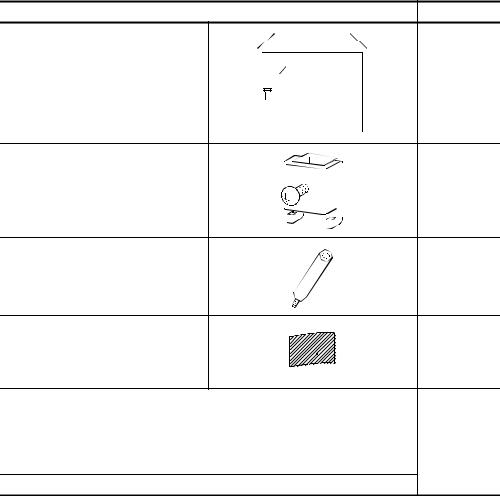
3. PACKING LIST
After unpacking, confirm that you have received the following products.
Product |
|
|
|
Quantity |
|
|
|
|
|
|
|
|
|
|
|
|
|
|
|
GOT main unit |
|
|
1 |
|||
|
|
|
|
|
|
|
|
|
|
|
|
|
|
|
|
|
|
|
|
|
Mounting fixture |
|
|
|
|
|
|
|
|
4 |
|
|
|
|
|
|
|
|
||
|
|||||||||
|
|
|
|
|
|
|
|
|
|
|
|
|
|
|
|
|
|
|
|
|
|
|
|
|
|
|
|
|
|
|
|
|
|
|
|
|
|
|
|
Communication
module securing fixture 3 (A956GOT, A956WGOT only)
Seal (A956WGOT only)
* For use when closing the bus connec-
1
tion board setting switch confirmation hole.
A950GOT-TBD(-M3)/SBD(-M3)/SBD(-M3)-B/LBD(-M3), A951GOT-QTBD(-M3)/QSBD(-M3)/QSBD(-M3)-B/QLBD(-M3), A951GOT-TBD(-M3)/SBD(-M3)/SBD(-M3)-B/LBD(-M3), A953GOT-TBD(-M3)/SBD(-M3)/SBD(-M3)-B/LBD(-M3), 1 A956GOT-TBD(-M3)/SBD(-M3)/SBD(-M3)-B/LBD(-M3) User's Manual (Hardware) *
A956WGOT-TBD User's Manual (Hardware) *
* Changes with the GOT you purchased.
A - 14

1 OVERVIEW |
1 |
|
|
|
|
This user's manual explains the specifications, handling and other information of the A950GOT/A951GOT/ A953GOT/A956GOT/A956WGOT graphic operation terminal module (abbreviated to the GOT).
The GOT can be used as an electronic operator panel which has achieved on its monitor screen the switch operation, lamp indication, data display, message display and other operations which were previously performed on an operator panel.
The following GOT types are available.
|
|
|
Rough Specifications |
|
|
|
Type |
|
|
|
|
|
|
Screen size |
Interface built into main unit |
Display section |
Display color |
Power |
||
|
[cm (inch)] |
[color] |
Supply type |
|||
|
|
|
||||
A950GOT-TBD |
|
|
|
|
|
|
|
|
|
|
|
|
|
A950GOT-SBD |
|
|
|
|
|
|
|
|
|
|
|
|
|
A950GOT-SBD-B |
|
|
|
|
|
|
|
|
|
|
|
|
|
A950GOT-LBD |
|
Built-in RS-422 |
|
|
|
|
A950GOT-TBD-M3 |
|
communication interface |
|
|
|
|
|
|
|
|
|
|
|
A950GOT-SBD-M3 |
|
|
|
|
|
|
|
|
|
|
|
|
|
A950GOT-SBD-M3-B |
|
|
|
|
|
|
|
|
|
|
|
|
|
A950GOT-LBD-M3 |
|
|
|
|
|
|
|
|
|
|
|
|
|
A951GOT-QTBD |
|
|
TBD(-M3): High-intensity TFT |
|
|
|
|
|
|
|
|
||
A951GOT-QSBD |
|
|
|
|
||
|
|
color |
|
|
||
|
|
|
|
|
||
A951GOT-QSBD-B |
|
|
liquid crystal |
TBD(-M3): 256 |
|
|
|
|
Built-in bus |
SBD(-M3)-B: High-intensity |
|
||
A951GOT-QLBD |
|
SBD(-M3), SBD(- |
|
|||
15 (6) |
communication interface |
STN color liquid crystal |
24VDC |
|||
|
M3)-B: 8 |
|||||
A951GOT-QTBD-M3 |
||||||
|
(For QCPU (Q Mode)) |
SBD(-M3): STN color |
|
|||
|
|
LBD(-M3): 2 |
|
|||
A951GOT-QSBD-M3 |
|
|
liquid crystal |
|
||
|
|
|
|
|||
|
|
|
LBD(-M3): Monochrome |
|
|
|
A951GOT-QSBD-M3-B |
|
|
|
|
||
|
|
liquid crystal |
|
|
||
|
|
|
|
|
||
A951GOT-QLBD-M3 |
|
|
|
|
||
|
|
|
|
|
||
|
|
|
|
|
|
|
A951GOT-TBD |
|
|
|
|
|
|
|
|
|
|
|
|
|
A951GOT-SBD |
|
|
|
|
|
|
|
|
|
|
|
|
|
A951GOT-SBD-B |
|
Built-in bus |
|
|
|
|
|
|
|
|
|
||
A951GOT-LBD |
|
communication interface |
|
|
|
|
A951GOT-TBD-M3 |
|
(For A/QnA/Motion control- |
|
|
|
|
|
|
ler CPU) |
|
|
|
|
A951GOT-SBD-M3 |
|
|
|
|
||
|
|
|
|
|
||
|
|
|
|
|
|
|
A951GOT-SBD-M3-B |
|
|
|
|
|
|
|
|
|
|
|
|
|
A951GOT-LBD-M3 |
|
|
|
|
|
|
|
|
|
|
|
|
OVERVIEW 2
SYSTEM CONFIGURATION 3
PERFORMANCE 4
OFNAMESPARTSTHETHEIR ANDSETTINGS
5
-PRE ROUGHOPERATIONPROCEDURE
6
HANDLING 7
ANDMAINTENANCE INSPECTION 8
DIRECTIVEEMC
1 - 1

The following GOT types are available.
|
|
|
Rough Specifications |
|
|
Type |
Screen size |
Interface built into main unit |
Display section |
Display color |
Power |
|
[cm (inch)] |
[color] |
Supply type |
||
|
|
|
|||
A953GOT-TBD |
|
|
|
|
|
|
|
|
|
|
|
A953GOT-SBD |
|
|
|
|
|
|
|
|
|
|
|
A953GOT-SBD-B |
|
|
|
|
|
|
|
|
|
|
|
A953GOT-LBD |
|
Built-in RS-232C |
|
|
|
A953GOT-TBD-M3 |
|
communication interface |
|
|
|
|
|
|
|
|
|
A953GOT-SBD-M3 |
|
|
TBD(-M3): High-intensity TFT |
|
|
|
|
|
|
|
|
A953GOT-SBD-M3-B |
|
|
color |
|
|
|
|
|
liquid crystal |
|
|
A953GOT-LBD-M3 |
15 (6) |
|
TBD(-M3): 256 |
|
|
|
|
SBD(-M3)-B: High-intensity |
|
||
A956GOT-TBD |
|
SBD(-M3), SBD(- |
|
||
|
|
STN color liquid crystal |
24VDC |
||
|
|
|
M3)-B: 8 |
||
A956GOT-SBD |
|
|
|||
|
|
SBD(-M3): STN color |
|
||
|
|
LBD(-M3): 2 |
|
||
|
|
|
|
||
A956GOT-SBD-B |
|
|
liquid crystal |
|
|
|
|
|
|
||
|
|
|
LBD(-M3): Monochrome |
|
|
A956GOT-LBD |
|
Built-in communication |
|
|
|
|
liquid crystal |
|
|
||
|
|
module interface |
|
|
|
A956GOT-TBD-M3 |
|
|
|
||
|
|
|
|
||
|
|
|
|
|
|
A956GOT-SBD-M3 |
|
|
|
|
|
|
|
|
|
|
|
A956GOT-SBD-M3-B |
|
|
|
|
|
|
|
|
|
|
|
A956GOT-LBD-M3 |
|
|
|
|
|
|
|
|
|
|
|
A956WGOT-TBD |
18 (7) |
Built-in communication |
|
|
|
board/module interface |
|
|
|
||
|
|
|
|
|
|
|
|
|
|
|
|
1 - 2

1.1 Features |
1 |
(1)Medium-size display device occupying minimum installation area
The A95 GOT/A956WGOT was made smaller in outline dimensions to greatly reduce the panel cut dimensions.
You can install the GOT according to your application.
For A95 |
GOT |
|
|
|
|
|
|
|
(4.84) |
|
A95 GOT's panel cut dimensions |
|
(5.35) |
|
|
156 (6.14) [+1.0 (0.04),-0 (0)] |
|
|
|
|
|
||
|
136 |
|
123 |
|
123.5 (4.86) [+1.0 (0.04),-0 (0)] |
|
|
|
|
||
164.5 (6.48) |
51 |
|
|
|
|
(2.01) |
|
|
|
||
|
|
|
|
|
|
|
|
6 (0.24) |
|
|
Unit (mm(inch)) |
|
|
|
|
|
|
59 mm (2.32 in) for A95 |
GOT-TBD,A95 |
|
GOT-SBD(-M3)-B,A95 GOT-QSBD(-M3)-B. |
||
For A956WGOT |
|
|
|
|
|
|
|
131.5 (5.18) |
|
123 (4.84) |
A956WGOT's panel cut dimensions |
|
|
|
205.5 (8.09) [+1.0 (0.04),-0 (0)] |
||
|
|
|
123.5 (4.86) [+1.0 (0.04),-0 (0)] |
||
|
|
|
|
||
215 (8.46) |
65.8 |
|
|
|
|
(2.59) |
|
|
|||
|
|
|
|
||
|
|
5 (0.20) |
|
|
Unit (mm(inch)) |
|
|
|
|
|
|
(2)Fast data transfer of OS and screen data by memory card
The PC card for OS and screen data can be created easily on a personal computer. By loading the created card into the memory card interface unit, you can exchange the OS and screen data rapidly. (RS-232C data transfer can also be made as conventionally.)
Also, a compact flash PC card can be used with the A956WGOT.
A95 GOT or A956WGOT
Commercially available PC card
|
OVERVIEW |
|
|
|
|
2 |
|
|
|
SYSTEM CONFIGURATION |
|
|
|
|
|
|
|
|
3 |
|
|
PERFORMANCE |
|
|
|
|
|
4 |
|
NAMES OF THE PARTS AND THEIR SETTINGS |
|
|
5 |
|
|
|
||
ROUGH PRE-OPERATION PROCEDURE |
||
6 |
|
|
A1SD59J-MIF
A956WGOT
Commercially available compact flash PC card
* ROM_BIOS cannot be installed with the compact flash PC card.
HANDLING 7
ANDMAINTENANCE INSPECTION 8
DIRECTIVEEMC
1.1 Features |
1 - 3 |
(3)Compatible with a wide variety of connection forms
The GOT models each contain their communication interfaces so that you can choose the connection form which meets your system.
The A951GOT-Q, A951GOT comes with a bus communication interface to make a bus connection for fast communication, the A953GOT has an RS-232C interface and A950GOT includes an RS422 communication interface to make a CPU direct connection or computer link connection.
The A956GOT used with a communication module can make a bus connection, MELSECNET connection or CC-Link connection.
The A956WGOT used with a communication module or communication board can make a bus connection, Direct connection to CPU, computer link connection, MELSECNET connection, CCLink connection or Ethernet connection.
(4)Heavy-duty body usable in rigorous environment and operation
The standard display section of the GOT complies with the IP67 and the NEMA4 Waterproof, Dustproof Standard and is usable in a wide range of environment.
(5)Maintenance function further enhanced in affinity with PLC Upgraded alarm history function
The GOT can support the failure occurrence counting function, cumulative failure time totalizing function and history printing function, and start ladder monitoring with the corresponding device searched with a single keystroke at the failure detail display time.
(6)Improvement of safety by upgraded security function
•Supporting the operation protective function using up to 16 levels of passwords, the GOT can hide the display or disable input operation according to the password level. You can achieve hidden screens and hidden operations and easily change the display data per GOT used.
•You can specify the time delay function (ON delay/OFF delay) of the touch switches, doublepushing switches and interlock conditions to reduce malfunctions due to wrong key pushing.
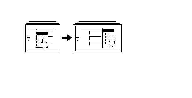
(7)Wide, easy-to-see screen (A956WGOT only)
The A956WGOT can lay out more objects on the screen than it is possible with the A95

 GOT. By utilizing the monitor screen data of the A95
 GOT, the A956WGOT enables numeric value entry without hiding the monitor screen with a window for numeric value entry. This is achieved by arranging the ten keys for numeric value input next to the monitor screen data.
For A95 GOT
GOT
Line1 98
Line2 
 458
458
Line3

 24
24
For A956WGOT
Line1 98
Line2 458
Line3 24
Numeric values can be entered without hiding the monitor screen with a window for numeric value entry.
1 - 4 |
1.1 Features |
2 SYSTEM CONFIGURATION |
1 |
|
|
|
|
This chapter explains the system configuration of the GOT.
2.1 Overall Configuration
OVERVIEW
2
(1) Overall configuration of the A95*GOT |
|
|
|
|
|
|
CONFIGURATION |
|||
The overall configuration of the A95*GOT is shown below. |
|
|
|
|
||||||
Communication cable/ |
Protective sheet |
Debug stand |
|
Backlight 3 |
|
|
|
SYSTEM |
||
module connected |
|
|
|
|
|
|
|
|||
For A950GOT |
|
|
|
|
|
|
|
|
||
RS-422 cable |
1 |
|
|
|
|
|
|
|
3 |
|
|
|
|
|
|
|
|
|
|
||
|
|
A9GT-50PSC |
A9GT-50STAND |
|
A9GT-50LT |
|
|
|
|
PERFORMANCE |
e.g. A30R4-25P |
|
|
|
|
|
|
|
|
||
For A951GOT-Q |
|
|
|
|
|
|
Bar Code Reader |
1 |
|
|
Bus cable for |
|
|
|
|
|
|
|
|||
|
|
|
|
|
|
|
|
|
||
QCPU(Q mode) |
1 |
|
|
|
|
|
|
|
|
|
|
|
|
|
|
|
|
4 |
|||
|
|
|
GOT |
|
|
|
|
|
||
|
|
|
|
|
|
Commercially available |
|
|
||
|
|
|
|
|
|
|
|
THEIR SETTINGS |
||
e.g. A9GT-QC150BS |
|
|
|
|
|
|
|
THE PARTS AND |
||
For A951GOT |
|
|
|
|
|
|
Personal computer |
NAMES OF |
||
Bus cable 1 |
|
|
|
|
|
|
||||
|
|
|
|
|
|
for drawing |
||||
|
|
|
|
|
|
|
||||
|
|
|
|
|
|
|
|
|||
e.g. A8GT-C12NB |
|
|
|
|
|
|
|
5 |
||
|
A95 GOT |
|
|
|
|
|
|
|
||
|
|
|
|
|
|
|
|
PRE-OPERATION |
|
|
For A953GOT |
|
|
|
|
|
|
|
|
|
|
RS-232C cable |
1 |
|
|
|
|
|
Commercially available |
|
PROCEDURE |
|
|
|
|
|
|
|
|
|
|||
Fabricated by |
|
|
|
|
|
|
|
ROUGH |
||
|
|
|
|
|
|
|
|
6 |
||
the user |
|
|
|
|
|
|
|
|
||
For A956GOT |
|
|
|
|
|
|
|
|
||
|
Memory card cable |
External I/O module |
Printer interface |
|
|
|
|
|||
Communication |
|
|
|
|
||||||
|
2 |
|
module |
1 |
|
|
|
|
||
module |
|
|
|
|
|
|
|
|||
|
|
|
|
|
|
|
|
|
|
|
|
|
A85GT-C05H |
A8GT-50KBF |
|
A9GT-50PRF |
|
|
|
HANDLING |
|
e.g. A9GT-Q71LP23 |
|
|
|
7 |
||||||
|
|
|
|
|
|
|
||||
|
|
|
|
|
|
|
|
|
||
PC card |
|
Memory card |
Numeric key panel |
Printer cable |
1 |
Printer 1 |
|
AND |
|
|
(Memory card) |
|
interface module 2 |
(e.g. key board) |
2 |
|
|
|
MAINTENANCE |
|
|
|
|
|
|
|
INSPECTION |
|||||
Commercially |
|
|
|
|
|
|
Commercially |
|
||
|
|
|
|
|
|
|
8 |
|||
available |
|
A1SD59J-MIF |
e.g. A8GT-TK |
|
e.g. AC30PI0-20P |
available |
|
|||
|
|
|
|
|
|
|
|
|
||
*1 For details of the system configuration, refer to the [GOT-A900 Series User's Manual (Connection System Manual)].
*2 For details on the system configuration, refer to the User's Manual of each module. *3 The A95*GOT-SBD(-M3)-B, A95*GOT-QSBD(-M3)-B and A95*GOT-TBD(-M3) do not
require their backlights to be replaced since they are installed with long-life backlights.
EMC DIRECTIVE
2.1 Overall Configuration |
2 - 1 |

(2)Overall configuration of the A956WGOT
The overall configuration of the A956WGOT is shown below.
|
Memory board |
Protective sheet |
|
Debug Stand |
Compact flash PC card |
|
|||
|
e.g.A9GT-FNB |
A9GT-50WPSC |
A9GT-50WSTAND |
Commercially available |
|
||||
Communication |
|
|
|
|
|
|
Bar Code Reader |
1 |
|
module |
1 |
|
|
|
|
|
|
||
|
|
|
|
|
|
|
|
||
|
|
|
|
GOT |
|
|
|
|
|
|
|
|
|
|
|
|
|
Commercially available |
|
e.g.A9GT-QJ71LP23 |
|
|
|
|
|
|
Personal computer |
|
|
|
|
|
|
|
|
for drawing |
|
||
|
|
|
|
|
|
|
|
|
|
Communication |
|
|
|
|
|
|
|
|
|
board |
1 |
|
|
|
|
|
|
|
|
|
|
|
|
A956WGOT |
|
|
|
|
|
e.g.A9GT-50WQBUSS |
|
|
|
|
|
|
Commercially available |
|
|
|
|
|
|
|
|
|
|
||
|
|
Memory card cable |
External I/O module |
Printer interface |
|
|
|||
|
|
|
|
2 |
|
module |
1 |
|
|
|
|
A85GT-C05H |
|
A8GT-50KBF |
|
A9GT-50PRF |
|
|
|
PC card |
Memory card |
|
Numeric key panel |
Printer cable |
1 |
Printer 1 |
|
||
(Memory card) |
interface module 2 |
|
(e.g. key board) |
2 |
|
|
|
||
|
|
|
|
|
|||||
Commercially |
|
|
|
|
|
|
Commercially |
|
|
available |
A1SD59J-MIF |
|
e.g. A8GT-TK |
|
e.g. AC30PI0-20P |
available |
|
||
*1 For details of the system configuration, refer to the [GOT-A900 Series User's Manual (Connection System Manual)].
*2 For details on the system configuration, refer to the User's Manual of each module.
2 - 2 |
2.1 Overall Configuration |

2.2 System Configuration of the GOT |
1 |
Each GOT incorporates a different type of communication interface and, therefore, the connection mode differs from GOT to GOT used.
The connections modes allowed for each GOT are shown below.
|
Bus connection |
CPU direct Connection |
|
Computer link connection |
|
|
||||
|
QCPU |
A/QnA/ |
RS-422 |
RS-232C |
MELSEC- |
RS-422 |
RS-232C |
CC-Link |
Ethernet |
|
Type |
Motion |
NET connec- |
connec- |
|||||||
(Q |
communica- |
communica- |
communica- |
communica- |
connection |
|||||
|
controller |
tion |
tion |
|||||||
|
mode) |
tion |
tion |
tion |
tion |
|
||||
|
CPU |
|
|
|
||||||
|
|
|
|
|
|
|
|
|
||
A950GOT |
|
|
|
|
|
|
|
|
|
|
A951GOT-
Q
A951GOT
A953GOT
A956GOT
*1
A956WGO
T*2
 : Connection possible
  : Connection not possible


 1 The A956GOT can be connected as shown above by the installation of the communication unit.


 2 The A956WGOT can be connected as shown above by the installation of the communication unit and the communication board.


 3 For details of each connection mode, refer to the GOT-A900 Series User's Manual (Connection System Manual).
2.3Component List
(1)List of Components Available for the A95*GOT
Component |
Type |
Description |
|
|
A950GOT-TBD |
High intensity TFT color liquid crystal, 256 colors, 1M byte built-in memory |
|
|
|
|
|
|
A950GOT-SBD |
STN color liquid crystal, 8 colors, 1M byte built-in memory |
|
|
|
|
|
|
A950GOT-SBD-B |
High intensity STN color liquid crystal, 8 colors, 1M built-in memory |
|
|
|
|
|
A950GOT |
A950GOT-LBD |
Monochrome liquid crystal, Monochrome, 1M byte built-in memory |
|
|
|
||
|
High intensity TFT color liquid crystal, 256 colors, 3M byte built-in memory, compatible with |
||
(Built-in RS-422 com- |
A950GOT-TBD-M3 |
||
optional OS |
|||
munication interface) |
|
||
|
|
||
|
A950GOT-SBD-M3 |
STN color liquid crystal, 8 colors, 3M byte built-in memory, compatible with optional OS |
|
|
|
|
|
|
A950GOT-SBD-M3-B |
High intensity STN color liquid crystal, 8 colors, 3M built-in memory, compatible with optional |
|
|
OS |
||
|
|
||
|
|
|
|
|
A950GOT-LBD-M3 |
Monochrome liquid crystal, Monochrome, 3M byte built-in memory, compatible with optional OS |
|
|
|
|
OVERVIEW 2
SYSTEM CONFIGURATION 3
PERFORMANCE 4
OFNAMESPARTSTHETHEIR ANDSETTINGS
5
-PRE ROUGHOPERATIONPROCEDURE
6
HANDLING 7
ANDMAINTENANCE INSPECTION 8
DIRECTIVEEMC
2.2 System Configuration of the GOT |
2 - 3 |

Component |
Type |
Description |
|
|
A951GOT-QTBD |
High intensity TFT color liquid crystal, 256 colors,1M byte built-in memory |
|
|
|
|
|
|
A951GOT-QSBD |
STN color liquid crystal, 8 colors,1M byte built-in memory |
|
|
|
|
|
|
A951GOT-QSBD-B |
High intensity STN color liquid crystal, 8 colors, 1M built-in memory |
|
A951GOT-Q |
|
|
|
A951GOT-QLBD |
Monochrome liquid crystal, Monochrome,1M byte built-in memory |
||
(Built-in bus communi- |
|||
|
|
||
|
High intensity TFT color liquid crystal, 256 colors, 3M byte built-in memory, compatible with |
||
cation interface for |
A951GOT-QTBD-M3 |
||
optional OS |
|||
QCPU |
|
||
|
|
||
(Q mode)) |
A951GOT-QSBD-M3 |
STN color liquid crystal, 8 colors, 3M byte built-in memory, compatible with optional OS |
|
|
|
|
|
|
A951GOT-QSBD-M3-B |
High intensity STN color liquid crystal, 8 colors, 3M built-in memory, compatible with optional |
|
|
OS |
||
|
|
||
|
|
|
|
|
A951GOT-QLBD-M3 |
Monochrome liquid crystal, Monochrome, 3M byte built-in memory, compatible with optional OS |
|
|
|
|
|
|
A951GOT-TBD |
High intensity TFT color liquid crystal, 256 colors,1M byte built-in memory |
|
|
|
|
|
|
A951GOT-SBD |
STN color liquid crystal, 8 colors,1M byte built-in memory |
|
|
|
|
|
|
A951GOT-SBD-B |
High intensity STN color liquid crystal, 8 colors, 1M built-in memory |
|
A951GOT |
|
|
|
A951GOT-LBD |
Monochrome liquid crystal, Monochrome,1M byte built-in memory |
||
(Built-in bus communi- |
|||
|
|
||
|
High intensity TFT color liquid crystal, 256 colors, 3M byte built-in memory, compatible with |
||
cation interface for A/ |
A951GOT-TBD-M3 |
||
optional OS |
|||
QnA/Motion controller |
|
||
|
|
||
CPU) |
A951GOT-SBD-M3 |
STN color liquid crystal, 8 colors, 3M byte built-in memory, compatible with optional OS |
|
|
|
|
|
|
A951GOT-SBD-M3-B |
High intensity STN color liquid crystal, 8 colors, 3M built-in memory, compatible with optional |
|
|
OS |
||
|
|
||
|
|
|
|
|
A951GOT-LBD-M3 |
Monochrome liquid crystal, Monochrome, 3M byte built-in memory, compatible with optional OS |
|
|
|
|
|
|
A953GOT-TBD |
High intensity TFT color liquid crystal, 256 colors,1M byte built-in memory |
|
|
|
|
|
|
A953GOT-SBD |
STN color liquid crystal, 8 colors,1M byte built-in memory |
|
|
|
|
|
|
A953GOT-SBD-B |
STN color liquid crystal, 8 colors, 1M built-in memory |
|
|
|
|
|
A953GOT |
A953GOT-LBD |
Monochrome liquid crystal, Monochrome,1M byte built-in memory |
|
|
|
||
|
High intensity TFT color liquid crystal, 256 colors,3M byte built-in memory, compatible with |
||
(Built-in RS-232C com- |
A953GOT-TBD-M3 |
||
optional OS |
|||
munication Interface) |
|
||
|
|
||
|
A953GOT-SBD-M3 |
STN color liquid crystal, 8 colors,3M byte built-in memory, compatible with optional OS |
|
|
|
|
|
|
A953GOT-SBD-M3-B |
High intensity STN color liquid crystal, 8 colors, 3M built-in memory, compatible with optional |
|
|
OS |
||
|
|
||
|
|
|
|
|
A953GOT-LBD-M3 |
Monochrome liquid crystal, Monochrome,3M byte built-in memory, compatible with optional OS |
|
|
|
|
|
|
A956GOT-TBD |
TFT color liquid crystal, 256 colors,1M byte built-in memory |
|
|
|
|
|
|
A956GOT-SBD |
STN color liquid crystal, 8 colors,1M byte built-in memory |
|
|
|
|
|
|
A956GOT-SBD-B |
High intensity STN color liquid crystal, 8 colors, 1M built-in memory |
|
|
|
|
|
A956GOT |
A956GOT-LBD |
Monochrome liquid crystal, Monochrome,1M byte built-in memory |
|
|
|
||
|
High intensity TFT color liquid crystal, 256 colors,3M byte built-in memory, compatible with |
||
(Built-in communication |
A956GOT-TBD-M3 |
||
optional OS |
|||
module Interface) |
|
||
|
|
||
|
A956GOT-SBD-M3 |
STN color liquid crystal, 8 colors,3M byte built-in memory, compatible with optional OS |
|
|
|
|
|
|
A956GOT-SBD-M3-B |
High intensity STN color liquid crystal, 8 colors, 3M built-in memory, compatible with optional |
|
|
OS |
||
|
|
||
|
|
|
|
|
A956GOT-LBD-M3 |
Monochrome liquid crystal, Monochrome,3M byte built-in memory, compatible with optional OS |
|
|
|
|
|
Bus Connection mod- |
A7GT-BUSS |
For A956GOT, for bus connection, small connector type (For A/QnA/Motion controller CPU) |
|
ule |
|||
|
|
||
|
|
|
|
Multidrop bus connec- |
A7GT-BUS2S |
For A956GOT, for multidrop bus connection, small connector type (For A/QnA/Motion controller |
|
tion module |
CPU) |
||
|
|||
|
|
|
|
Protective sheet |
A9GT-50PSC |
Transparent protective sheet for A95 GOT |
|
|
|
|
|
Backlight |
A9GT-50LT |
Backlight for A95 GOT-SBD (-M3), A95 GOT-LBD (-M3) |
|
|
|
|
2 - 4 2.3 Component List

|
|
|
|
|
|
|
Component |
Type |
Description |
|
|
1 |
|
Debug stand |
A9GT-50STAND |
Debug stand for A95 GOT |
|
|
|
|
|
|
|
|
|
|
|
Attachment |
A85GT-95ATT |
For replacement from A85 GOT to A95 GOT |
|
OVERVIEW |
|
|
|
|
|
|
|
|
|
|
|
|
|
|
|
|
|
|
|
|
|
|
|
|
|
|
|
|
|
|
|
|
|
|
|
2 |
|
|
|
|
|
|
SYSTEM CONFIGURATION |
|
|
|
|
|
|
|
|
|
|
|
|
|
|
|
|
|
|
|
|
3 |
|
|
|
|
|
|
PERFORMANCE |
|
|
|
|
|
|
|
|
|
|
|
|
|
4 |
|
|
|
|
NAMES OF |
THE PARTS AND THEIR SETTINGS |
|
|
|
|
|
|
|
5 |
|
|
|
|
|
|
|
|
|
|
|
ROUGH PRE-OPERATION PROCEDURE |
|
||
|
|
|
|
|
|
|
|
|
|
|
|
|
|
|
|
|
|
|
6 |
|
|
|
|
|
|
HANDLING |
|
|
|
|
|
|
|
|
|
|
|
|
|
|
|
|
|
|
|
|
7 |
|
|
|
|
|
|
MAINTENANCE AND INSPECTION |
|
|
|
|
|
|
|
|
|
|
|
|
|
|
|
|
|
|
|
|
8 |
|
|
|
|
|
|
EMC DIRECTIVE |
|
|
|
|
|
|
|
|
2.3 Component List |
2 - 5 |

(2) List of Components Available for the A956WGOT
Component |
Type |
Description |
|
A956WGOT |
A956WGOT-TBD |
256color, 1M byte Built-in memory (Possible to expand to a maximum of 9M bytes by using a |
|
memory board), 24VDC |
|||
|
|
||
|
|
|
|
Bus connection board |
A9GT-50WQBUSS |
For bus connection, small connector type (For Q (Q mode) CPU) |
|
|
|
||
A9GT-50WBUSS |
For bus connection, small connector type (For A/QnA/Motion controller CPU) |
||
|
|||
|
|
|
|
|
A9GT-50WRS2 |
For Direct connection to CPU/Computer link connection/Microcomputer connection and RS- |
|
Serial communication |
232C connection |
||
|
|||
board |
|
|
|
A9GT-50WRS4 |
For Direct connection to CPU/Computer link connection/Microcomputer connection and RS- |
||
|
422 connection |
||
|
|
||
|
|
|
|
Protective sheet |
A9GT-50WPSC |
Transparent protective sheet for A956WGOT |
|
|
|
|
|
Debug stand |
A9GT-50WSTAND |
Debug stand for A956WGOT |
|
|
|
|
|
Compact flash card |
--- |
Commercially available Compact Flash PC card |
|
|
|
|
|
|
A9GT-FNB |
Exclusively used for optional OS storage |
|
|
|
|
|
|
A9GT-FNB1M |
For optional function OS storage + built-in memory extension, 1M byte |
|
|
|
|
|
|
A9GT-FNB2M |
For optional function OS storage + built-in memory extension, 2M byte |
|
|
|
|
|
|
A9GT-FNB4M |
For optional function OS storage + built-in memory extension, 4M byte |
|
|
|
|
|
|
A9GT-FNB8M |
For optional function OS storage + built-in memory extension, 8M byte |
|
Memory board |
|
|
|
A9GT-QFNB |
Exclusively used for optional OS storage |
||
|
|||
|
(MELSEC-Q Ladder monitor compatible) |
||
|
|
||
|
|
|
|
|
A9GT-QFNB4M |
For optional function OS storage + built-in memory extension, 4M byte |
|
|
(MELSEC-Q Ladder monitor compatible) |
||
|
|
||
|
|
|
|
|
A9GT-QFNB8M |
For optional function OS storage + built-in memory extension, 8M byte |
|
|
(MELSEC-Q Ladder monitor compatible) |
||
|
|
||
|
|
|
2 - 6 |
2.3 Component List |

(3) List of Components Available for the A95*GOT/A956WGOT
Component |
Type |
Description |
||
Bus Connection module |
A9GT-BUSSU |
For A956GOT/A956WGOT, for bus connection, small connector type (For A/QnA/Motion con- |
||
troller CPU) |
|
|||
|
|
|
||
|
|
|
||
|
A9GT-QBUS2SU |
For A956GOT/A956WGOT, for multidrop bus connection, small connector type (For QCPU (Q |
||
Multidrop bus connec- |
mode)) |
|
||
|
|
|||
tion module |
A9GT-BUS2SU |
For A956GOT/A956WGOT, for multidrop bus connection, small connector type (For A/QnA/ |
||
|
Motion controller CPU) |
|
||
|
|
|
||
|
|
|
||
|
A7GT-J71AP23 |
For A956GOT/A956WGOT, for MELSECNET(II) optical link connection, for use as local station |
||
|
|
|
||
Data link module |
A7GT-J71AR23 |
For A956GOT/A956WGOT, for MELSECNET(II) coaxial link connection, for use as local sta- |
||
tion |
|
|||
|
|
|
||
|
|
|
||
|
A7GT-J71AT23B |
For A956GOT/A956WGOT, for MELSECNET/B connection, for use as local station |
||
|
|
|
||
|
A9GT-QJ71LP23 |
For A956GOT/A956WGOT, for MELSECNET/10 optical loop network connection, for use as |
||
|
ordinary station *5 |
|
||
|
|
|
||
|
A9GT-QJ71BR13 |
For A956GOT/A956WGOT, for MELSECNET/10 coaxial bus network connection, for use as |
||
|
ordinary station *5 |
|
||
Network module |
|
|
||
A7GT-J71LP23 |
For A956GOT/A956WGOT, for MELSECNET/10 optical loop network connection, for use as |
|||
|
||||
|
ordinary station *5 |
|
||
|
|
|
||
|
A7GT-J71BR13 |
For A956GOT/A956WGOT, for MELSECNET/10 coaxial bus network connection, for use as |
||
|
ordinary station *5 |
|
||
|
|
|
||
CC-Link communica- |
A8GT-J61BT13 |
For A956GOT/A956WGOT, for CC-Link connection, for use as intelligent device station |
||
tion module |
A8GT-J61BT15 |
For A956GOT/A956WGOT, for CC-Link connection, for use as remote device station |
||
|
|
|
|
|
Ethernet communica- |
A9GT-J71E71-T |
For A956GOT/A956WGOT, for Ethernet connection |
||
tion module |
||||
|
|
|
||
|
|
|
|
|
External I/O module |
A8GT-50KBF |
For external I/O equipment connection |
|
|
|
|
|
|
|
Numeric keypad panel |
A8GT-TK |
Data entry Numeric Keypad Panel |
|
|
|
|
|
|
|
Memory card interface |
A1SD59J-MIF |
For PC card loading |
|
|
module |
|
|||
|
|
|
||
|
|
|
|
|
PC card |
--- |
SRAM type PC card |
*6 Refer to the relevant document |
|
Printer interface module |
A9GT-50PRF |
For printer connection |
|
|
|
|
|
|
|
|
|
Printer compliant with ESC/P24-J84(ESC/P |
|
|
Printer |
--- |
command compatible) *1 |
|
|
Hewlett Packard printers (PLC command com- |
*6 Refer to the relevant document |
|||
|
|
|||
|
|
patible) |
|
|
|
|
|
|
|
Bar code reader |
--- |
Commercially available bar-code reader |
|
|
|
|
|
|
|
Bus extension connec- |
A9GT-QCNB |
Used for connection of the QCPU (Q mode) long-distance bus. |
||
tor box |
||||
|
|
|
||
|
|
|
||
Bus connector conver- |
A7GT-CNB |
For conversion from large type connector to small type connector |
||
sion box |
(Used for connecting the CPU long-distance bus of the A/QnA Motion controller.) |
|||
|
||||
|
|
|
|
|
1
OVERVIEW 2
SYSTEM CONFIGURATION 3
PERFORMANCE 4
OFNAMESPARTSTHETHEIR ANDSETTINGS
5
-PRE ROUGHOPERATIONPROCEDURE
6
HANDLING 7
ANDMAINTENANCE INSPECTION 8
DIRECTIVEEMC
2.3 Component List |
2 - 7 |
Component |
|
Type |
|
Description |
|
|
|
QC06B |
Cable length 0.6m |
|
|
|
|
|
|
|
|
|
|
QC12B |
Cable length 1.2m |
|
For connection between GOT and QCPU (Q |
|
|
|
|
|
|
|
|
QC30B |
Cable length 3.0m |
|
mode) |
|
|
|
|
|
For connection between GOT and GOT |
|
|
QC50B |
Cable length 5.0m |
|
|
|
|
|
|
||
|
|
|
|
|
|
Bus connection cable |
QC100B |
Cable length 10.0m |
|
|
|
for QCPU (Q mode) |
|
|
|
|
|
|
A9GT-QC150BS |
Cable length 15.0m |
|
|
|
|
|
|
|
|
|
|
|
A9GT-QC200BS |
Cable length 20.0m |
|
For connection between GOT and QCPU (Q |
|
|
|
|
|
|
|
|
A9GT-QC250BS |
Cable length 25.0m |
|
mode) (A9GT-QCNB required) |
|
|
|
|
|
For connection between GOT and GOT |
|
|
A9GT-QC300BS |
Cable length 30.0m |
|
|
|
|
|
|
||
|
|
|
|
|
|
|
|
A9GT-QC350BS |
Cable length 35.0m |
|
|
|
|
|
|
|
|
|
|
AC06B |
Cable length 0.6m |
|
|
|
|
|
|
|
|
|
|
AC12B |
Cable length 1.2m |
|
|
|
|
|
|
|
|
|
|
AC30B |
Cable length 3.0m |
|
For connection between QnACPU Type/ |
|
|
|
|
|
|
|
|
AC50B |
Cable length 5.0m |
|
AnCPU Type/motion controller CPU and |
|
|
|
|
|
A7GT-CNB |
|
|
AC12B-R |
Right angle, cable length 1.2m |
|
|
|
|
|
|
||
|
|
|
|
|
|
|
|
AC30B-R |
Right angle, cable length 3.0m |
|
|
|
|
|
|
|
|
|
|
AC50B-R |
Right angle, cable length 5.0m |
|
|
|
|
|
|
|
|
|
|
A1SC07B |
Cable length 0.7m |
|
For connection between GOT and |
|
|
|
|
|
|
|
|
A1SC12B |
Cable length 1.2m |
|
QnASCPU Type/AnSCPU Type/motion con- |
|
|
A1SC30B |
Cable length 3.0m |
|
troller CPU |
|
|
|
|
|
For connection between GOT and GOT |
|
|
A1SC50B |
Cable length 5.0m |
|
|
|
|
|
|
||
|
|
|
|
|
|
|
|
A8GT-C12NB |
Cable length 1.2m |
|
For connection between QnASCPU Type/ |
|
|
|
|
|
|
|
|
A8GT-C30NB |
Cable length 3.0m |
|
AnSCPU Type/motion controller CPU and |
|
|
|
|
|
A7GT-CNB |
|
|
A8GT-C50NB |
Cable length 5.0m |
|
|
|
|
|
|
||
|
|
|
|
|
|
|
|
A1SC-C05NB |
Cable length 0.5m |
|
|
|
|
|
|
|
|
|
|
A1SC-C07NB |
Cable length 0.7m |
|
For connection between GOT and QnACPU |
|
|
|
|
|
Type/AnCPU Type/motion controller CPU |
|
|
A1SC-C30NB |
Cable length 3.0m |
|
|
|
|
|
|
|
|
Bus connection cable |
A1SC-C50NB |
Cable length 5.0m |
|
|
|
|
|
|
|
|
|
|
|
A8GT-C100EXSS |
Cable length 10.0m |
|
For connection between GOT and |
|
|
|
|
|
QnASCPU Type/AnSCPU Type/motion con- |
|
|
A8GT-C200EXSS |
Cable length 20.0m |
|
|
|
|
|
troller CPU |
||
|
|
|
|
|
|
|
|
|
|
|
|
|
|
A8GT-C300EXSS |
Cable length 30.0m |
|
For connection between GOT and |
|
|
|
A7GT-CNB |
||
|
|
|
|
|
|
|
|
|
|
|
|
|
|
A8GT-C100EXSS-1 |
Cable length 10.0m |
|
For connection between GOT and |
|
|
|
|
|
QnASCPU Type/AnSCPU Type/motion con- |
|
|
A8GT-C200EXSS-1 |
Cable length 20.0m |
|
|
|
|
|
troller CPU |
||
|
|
|
|
|
|
|
|
|
|
|
|
|
|
A8GT-C300EXSS-1 |
Cable length 30.0m |
|
For connection between GOT and |
|
|
|
A7GT-CNB *7 |
||
|
|
|
|
|
|
|
|
A8GT-C100BS |
Cable length 10.0m |
|
|
|
|
|
|
|
|
|
|
A8GT-C200BS |
Cable length 20.0m |
|
For connection between GOT and GOT |
|
|
|
|
|
|
|
|
A8GT-C300BS |
Cable length 30.0m |
|
|
|
|
|
|
|
|
|
|
A370C12B-S1 |
Cable length 1.2m |
|
For connection between GOT and motion |
|
|
|
|
|
controller CPU |
|
|
A370C25B-S1 |
Cable length 2.5m |
|
|
|
|
|
|
|
|
|
|
A370C12B |
Cable length 1.2m |
|
For connection between motion controller |
|
|
A370C25B |
Cable length 2.5m |
|
CPU and A7GT-CNB |
|
|
|
|
|
|
|
|
A9GT-J2C10B |
Cable length 1.0m |
|
For connection between GOT and |
|
|
|
A0J2HCPU |
||
|
|
|
|
|
|
|
|
|
|
|
|
|
|
|
|
|
|
2 - 8 |
2.3 Component List |
|
|
|
|

Component |
Type |
Description |
||
|
AC30R4-25P |
Cable length 3m (D-sub 25-pin at both ends) |
For connection between GOT and A/ |
|
|
|
|
||
RS-422 cable |
AC100R4-25P |
Cable length 10m (D-sub 25-pin at both ends) |
QnACPU |
|
|
|
For connection between GOT and FXCPU |
||
AC300R4-25P |
Cable length 30m (D-sub 25-pin at both ends) |
|||
|
||||
|
|
|||
|
|
|
|
|
|
--- |
For connection between GOT and computer link module *2 |
||
|
QC30R2 |
Cable length 3m |
For connection between GOT and QCPU |
|
|
|
|
|
|
|
AC30R2-9P |
Cable length 3m (D-sub 9-pin, D-sub 25-pin) |
For connection between GOT and personal |
|
|
computer for data transfer |
|||
|
|
|
||
|
|
|
|
|
|
AC30R2-9SS |
Cable length 3m (D-sub 9-pin at both ends) |
|
|
|
|
|
|
|
RS-232C cable *3 |
|
|
For connection between GOT and personal |
|
AC30R2 |
Cable length 3m (D-sub 25-pin at both ends) |
computer for data transfer |
||
|
||||
|
|
|
(9-pin conversion connector required) |
|
|
|
|
|
|
|
AC30N2A |
Cable length 3m (D-sub 25-pin at both ends) |
|
|
|
|
|
|
|
|
--- |
For connection between GOT and computer link module *2 |
||
|
--- |
For connecting the GOT with the power supply unit of the bar code reader *4 |
||
Printer cable *4 |
AC30PIO-20P |
Cable length 3m |
For connection between GOT and printer |
|
|
|
|
|
|
GT Designer |
--- |
Screen creation software for GOT900 series |
|
|
|
|
|
||
GT Designer 2 |
--- |
|
||
|
|
|||
|
|
|
|
|
*1 The printer of ESC/P raster specifications such as the PM series cannot be connected and used with the GOT.
*2 The RS-422/RS-232C cable for use between GOT and computer link module should be fabricated on the user side by referring to the [GOT-A900 Series User's Manual (Connection System Manual)].
*3 The RS-232C cable may be fabricated by the user. The RS-232C cable can also be fabricated by the user.
Refer to the following manual for details of the cable specifications.
When GT Designer is used: GT Works Version  /GT Designer Version
  Reference Manual When GT Designer2 is used: GT Designer2 Version
  Operating Manual
*4 The printer cable may be fabricated by the user.
Refer to [A9GT-50PRF type Printer interface module User’s Manual] for full information on the specifications needed to fabricate the cable.
*5 For the A9GT-QJ71LP23 and A9GT-QJ71BR13, the device range (QCPU, QnACPU, ACPU) that can be monitored changes depending on the communication driver.
When the A7GT-J71LP23 or A7GT-J71BR13 is mounted, only the device range of the AnA can be monitored. *6 Relevant document Some devices have been concluded to be applicable for GOT900 series by Mitsubishi.
For details of the devices, refer to the relevant document "List of valid devices applicable for GOT900 series " (Technical bulletin T10-0028).
Please contact your local Mitsubishi representative for the document, if necessary.
The GOT may not operate correctly if a device other than described in the document is used.
*7 The A8GT-C100EXSS-1, A8GT-C200EXSS-1, and A8GT-C300EXSS-1 are composed of the A8GT-EXCNB (0.5m) and the
A8GT-C100BS (10m), A8GT-C200BS (20m), and A8GT-C300BS (30m) respectively. When calculating the cable length, the A8GT-EXCNB‘s cable length can be ignored.
2.4 Software Packages to be Used
When a GOT is used, a software package of the applicable version or later is required. The versions of the software packages required for each GOT are shown below.
1
OVERVIEW 2
SYSTEM CONFIGURATION 3
PERFORMANCE 4
OFNAMESPARTSTHETHEIR ANDSETTINGS
5
-PRE ROUGHOPERATIONPROCEDURE
6
HANDLING 7
ANDMAINTENANCE INSPECTION 8
DIRECTIVEEMC
2.4 Software Packages to be Used |
2 - 9 |

|
Compatible software package |
||
Type |
GT Works 2 |
GT Works |
|
|
GT Designer 2 |
GT Designer |
|
A950GOT-TBD(-M3) |
|
SW0D5C-GTWORKS-E Version A or later, SW4D5C-GOTR- |
|
|
PACKE Version A or later |
||
|
|
||
|
|
|
|
A950GOT-SBD(-M3) |
|
SW0D5C-GTWORKS-E Version A or later, SW1D5C-GOTRE- |
|
|
|
PACK Version H or later |
|
A950GOT-LBD(-M3) |
|
||
|
|
|
|
A951GOT-QTBD(-M3) |
|
SW0D5C-GTWORKS-E Version A or later, SW4D5C-GOTR- |
|
|
PACKE Version A or later |
||
|
|
||
|
|
|
|
A951GOT-QSBD(-M3) |
|
SW0D5C-GTWORKS-E Version A or later, SW3D5C-GOTRE- |
|
|
|
PACK Version C or later |
|
A951GOT-QLBD(-M3) |
|
||
|
|
|
|
A951GOT-TBD(-M3) |
|
SW0D5C-GTWORKS-E Version A or later, SW4D5C-GOTR- |
|
|
PACKE Version A or later |
||
|
|
||
|
|
|
|
A951GOT-SBD(-M3) |
SW1D5C-GTWK2-E A or later |
SW0D5C-GTWORKS-E Version A or later, SW1D5C-GOTRE- |
|
|
SW1D5C-GTD2-E A or later |
PACK Version H or later |
|
A951GOT-LBD(-M3) |
|||
|
|
|
|
A953GOT-TBD(-M3) |
|
SW0D5C-GTWORKS-E Version A or later, SW4D5C-GOTR- |
|
|
PACKE Version A or later |
||
|
|
||
|
|
|
|
A953GOT-SBD(-M3) |
|
SW0D5C-GTWORKS-E Version A or later, SW1D5C-GOTRE- |
|
|
|
PACK Version H or later |
|
A953GOT-LBD(-M3) |
|
||
|
|
|
|
A956GOT-TBD(-M3) |
|
SW0D5C-GTWORKS-E Version A or later, SW4D5C-GOTR- |
|
|
PACKE Version A or later |
||
|
|
||
|
|
|
|
A956GOT-SBD(-M3) |
|
SW0D5C-GTWORKS-E Version A or later, SW1D5C-GOTRE- |
|
|
|
PACK Version H or later |
|
A956GOT-LBD(-M3) |
|
||
|
|
|
|
A956WGOT-TBD |
|
SW5D5C-GTWORKS-E Version K or later, SW5D5C-GOTR- |
|
|
PACKE Version K or later |
||
|
|
||
|
|
|
|
A950GOT-SBD(-M3)-B |
|
|
|
|
|
|
|
A951GOT-QSBD(-M3)-B |
SW1D5C-GTWK2-E Version Q or later |
SW5D5C-GTWORKS-E Version Q or later |
|
|
|||
A951GOT-SBD(-M3)-B |
|||
SW1D5C-GTD2-E Version Q or later |
SW5D5C-GOTRE-PACK Version Q or later |
||
|
|||
A953GOT-SBD(-M3)-B |
|||
|
|
||
|
|
|
|
A956GOT-SBD(-M3)-B |
|
|
|
|
|
|
|
2.5 Unusable Conventional Products
The following conventional products cannot be used with this GOT.
Component |
Type |
|
Bus connection board |
A9GT-BUSS, A9GT-BUS2S |
|
|
|
|
Bus connection module |
A7GT-BUS, A9GT-BUS2 |
|
|
|
|
Serial communication board |
A9GT-RS2, A9GT-RS4 |
|
|
|
|
Serial communication module |
A8GT-RS2, A8GT-RS4 |
|
|
|
|
Backlight |
A9GT-70LTT, A9GT-70LTS, A9GT-70LTTB, A9GT-80LTT, A8GT-70LTT, A8GT-70LTS, A8GT-50LT |
|
|
|
|
Ladder monitoring cassette |
A8GT-MCAM |
|
|
|
|
Extension memory cassette |
A8GT-MCA1MFDW, A8GT-MCA2MFDW, A8GT-MCA3MFDW |
|
|
|
|
Extension memory board |
A9GT-FNB, A9GT-FNB1M, A9GT-FNB2M, A9GT-FNB4M |
|
|
|
|
Protective sheet |
A9GT-80PSC, A9GT-80PSCL, A9GT-70PSC, A9GT-70PSCL, A9GT-60PSC, A9GT-60PSCL, |
|
A8GT-70PSCE, A8GT-70PSNE, A8GT-70PSCS, A8GT-70PSNS, A8GT-50PSC, A8GT-50PSN |
||
|
||
|
|
|
Printer interface module |
A8GT-70PRF, A8GT-50PRF |
|
|
|
|
External I/O module |
A9GT-70KBF, A8GT-70KBF |
|
|
|
|
Debug stand |
A9GT-80STAND, A9GT-70STAND, A8GT-70STAND, A8GT-50STAND |
|
|
|
|
Option module mounting fixture |
A8GT-50STE |
|
|
|
2 - 10 2.5 Unusable Conventional Products
Loading...