


 Loading...
Service Manual
of
PM-8000
Portable Patient Monitor

Copyright
SHENZHEN MINDRAY® BIO-MEDICAL ELECTRONICS CO., LTD. 2002
Version: |
2.0 |
Issued date: |
2005/07/24 |
P/N: |
8000-20-10282 |
Statement
SHENZHEN MINDRAY® BIO-MEDICAL ELECTRONICS CO., LTD. (hereinafter called Mindray) owns all rights to this unpublished work and intends to maintain this work as confidential. Mindray may also seek to maintain this work as an unpublished copyright. This publication is to be used solely for the purposes of reference, operation, maintenance, or repair of Mindray equipment. No part of this can be disseminated for other purposes.
In the event of inadvertent or deliberate publication, Mindray intends to enforce its rights to this work under copyright laws as a published work. Those having access to this work may not copy, use, or disclose the information in this work unless expressly authorized by Mindray to do so.
All information contained in this publication is believed to be correct. Mindray shall not be liable for errors contained herein nor for incidental or consequential damages in connection with the furnishing, performance, or use of this material. This publication may refer to information and protected by copyrights or patents and does not convey any license under the patent rights of Mindray, nor the rights of others. Mindray does not assume any liability arising out of any infringements of patents or other rights of third parties.
Content of this manual is subject to changes without prior notice.
PROPERTY OF
SHENZHEN MINDRAY® BIO-MEDICAL ELECTRONICS CO., LTD.
ALL RIGHTS RESERVED
Responsibility on the manufacturer party
Service Manual of PM-8000 Portable Patient Monitor (V2.0) |
I |

Mindray is responsible for safety, reliability and performance of this equipment only in the condition
that:
•all installation, expansion, change, modification and repair of this equipment are conducted by Mindray qualified personnel; and,
•applied electrical appliance is in compliance with relevant National Standards; and,
•the monitor is operated under strict observance of this manual.
′ NOTE ′
This equipment is not intended for family usage.
Warning 
This monitor is not a device for treatment purpose.
It is important for the hospital or organization that employs this equipment to carry out a reasonable maintenance schedule. Neglect of this may result in machine breakdown or injury of human health.
Upon request, Mindray may provide, with compensation, necessary circuit diagrams, calibration illustration list and other information to help qualified technician to maintain and repair some parts, which Mindray may define as user serviceable.
II |
Service Manual of PM-8000 Portable Patient Monitor (V2.0) |

Warranty
Workmanship & Materials
Mindray guarantees new equipment other than accessories to be free from defects in workmanship and materials for a period of one year (six months for multi-site probes and SpO2 sensor) from date of shipment under normal use and service. Mindray's obligation under this warranty is limited to repairing, at Mindray’s option, any part which upon Mindray's examination proves defective.
THIS WARRANTY IS EXCLUSIVE AND IS IN LIEU OF ALL OTHER WARRANTIES, EXPRESSED OR IMPLIED, INCLUDING WARRANTIES OF MERCHANT ABILITY OR FITNESS FOR ANY PARTICULAR PURPOSE.
Exemptions
Mindray's obligation or liability under this warranty does not include any transportation or other charges or liability for direct, indirect or consequential damages or delay resulting from the improper use or application of the product or the substitution upon it of parts or accessories not approved by Mindray or repaired by anyone other than a Mindray authorized representative.
This warranty shall not extend to any instrument which has been subjected to misuse, negligence or accident; any instrument from which Mindray's original serial number tag or product identification markings have been altered or removed, or any product of any other manufacturer.
Safety, Reliability and Performance
Mindray is not responsible for the effects on safety, reliability and performance of the PM-8000 Portable Patient Monitor if:
■assembly operations, extensions, re-adjusts, modifications or repairs are carried out by persons other than those authorized by Mindray.
■the PM-8000 Portable Patient Monitor is not used in accordance with the instructions for use, or the electrical installation of the relevant room does not comply with NFPA 70: National Electric Code or NFPA 99: Standard for Health Care Facilities (Outside the United States, the relevant room must comply with all electrical installation regulations mandated by the local and regional bodies of government).
Service Manual of PM-8000 Portable Patient Monitor (V2.0) |
III |

Return Policy
Return Procedure
In the event that it becomes necessary to return a unit to Mindray, the following procedure should be
followed:
1.Obtain return authorization. Contact the Mindray Service Department and obtain a Customer Service Authorization (Mindray) number. The Mindray number must appear on the outside of the shipping container. Return shipments will not be accepted if the Mindray number is not clearly visible. Please provide the model number, serial number, and a brief description of the reason for return.
2.Freight policy. The customer is responsible for freight charges when equipment is shipped to Mindray for service (this includes customs charges).
Company Contact
Address: Mindray building keji 12th road south hi-tech industrial park nanshan Shenzhen, P.R.China
Phone: +86 755 26582658/26582888 Fax: +86 755 26582680
Free hot line: +86 800 830 3312
EC Representative
Name: |
Shanghai International Holding Corp. GmbH(Europe) |
|
Address: |
Eiffestrasse 80 D-20537 Hamburg Germany |
|
Phone: |
+49 |
40 2513174 |
Fax: |
+49 |
40 255726 |
IV |
Service Manual of PM-8000 Portable Patient Monitor (V2.0) |

Preface
This manual gives detailed description to PM-8000 Portable Patient Monitor concerning its performance, operation, and other safety information. Reading through this manual is the first step for the user to get familiar with the equipment and make the best out of it.
Following symbols indicates some important facts that you have to pay special attention to:
Warning  Points to be noted to avoid injury to the patient and the operator.
 Caution
  Points to be noted to avoid damage to the equipment.
′ NOTE ′ Points to be noted.
This manual is intended for persons who are trained in the use of this field and have adequate experience in operation of monitoring equipment.
Service Manual of PM-8000 Portable Patient Monitor (V2.0) |
V |

|
|
Content |
|
Chapter 1 Introduction ........................................................................................................................ |
1-1 |
||
I. |
General |
.................................................................................................................................... |
1-1 |
II. |
Appearance............................................................................................................................ |
1-2 |
|
|
2.1 Screen .................................................................................................................display |
1-2 |
|
|
2.2 Button .............................................................................................................Functions |
1-6 |
|
|
2 3 ................................................................................................................... |
Interfaces |
1-8 |
|
2 4 Built ......................................................................................-in rechargeable battery |
1-10 |
|
III. Hardware ................................................................................................................principle |
1-11 |
||
|
3 1 ............................................................................................................ |
Power board |
1-12 |
|
3 2 ..................................................................................PM-8000 main control board |
1-13 |
|
|
3 3 .................................................................................................... |
Structure diagram |
1-14 |
|
3 4 .............................................................................................................. |
Description |
1-14 |
|
3 5 .................................................................Button schematic diagram and principle |
1-16 |
|
|
3.6 Maintenance ..........................................................................part of TR60-A recorder |
1-17 |
|
Chapter 2 Monitor ......................................................................................Functions and Principles |
2-1 |
||
I. Introduction ............................................................................................................................... |
2-1 |
||
II. ECG/RESP .............................................................................................................parameters |
2-2 |
||
|
2.1 ECG................................................................................................................................. |
2-2 |
|
|
2.2 RESP ............................................................................................................................... |
2-2 |
|
|
2.3 NIBP ............................................................................................................................... |
2-3 |
|
|
2.4 SpO2 ............................................................................................................................... |
2-3 |
|
|
2.5 TEMP.............................................................................................................................. |
2-4 |
|
|
2.6 IBP .................................................................................................................................. |
2-4 |
|
Chapter 3 Checks ................................................................................................................and Tests |
3-1 |
||
I. |
System .........................................................................................................................checks |
3-1 |
|
II. Testing and ....................................................................................calibrating each parameter |
3-9 |
||
Chapter 4 Troubleshooting ................................................................................................................. |
4-1 |
||
I. Disassembly .............................................................................graph of each part of PM-8000 |
4-1 |
||
II. Troubleshooting ........................................................................................................guidance |
4-2 |
||
Chapter 5 Installation.......................................................................................................................... |
5-1 |
||
I. |
Unpack .................................................................................................................inspection |
5-1 |
|
II. |
Preparations ................................................................................................before power-on |
5-1 |
|
III. Turn on ...................................................................................................................the power |
5-1 |
||
IV. Other precautions.................................................................................................................... |
5-1 |
||
Chapter 6 Basic Operations ................................................................................................................ |
6-1 |
||
|
|
|
|
|
|
Service Manual of PM - 8000 Portable Patient Monitor (V2.0) |
1 |

I. Basic operation guidance........................................................................................................... |
6-1 |
|
II. Use PM-8000............................................................................................................................ |
6-1 |
|
Chapter 7 Cleaning and Disinfection.................................................................................................. |
7-1 |
|
I. |
Maintenance checks................................................................................................................ |
7-1 |
II. General cleaning....................................................................................................................... |
7-1 |
|
III. Sterilization ............................................................................................................................. |
7-2 |
|
IV. Precautions and cleaning ........................................................................................................ |
7-3 |
|
V. IBP transducer cleaning and disinfection reusable ........................................................... |
7-4 |
|
VI. |
TEMP sensor cleaning and disinfection (reusable) ............................................................. |
7-6 |
Chapter 8 Maintenance ....................................................................................................................... |
8-1 |
|
Chapter 9 Network Link ..................................................................................................................... |
9-1 |
|
I. |
Network performance ............................................................................................................. |
9-1 |
II. Application ............................................................................................................................... |
9-1 |
|
Appendix I: System Alarm Prompt................................................................................................... |
AI-i |
|
Appendix II: Product Specifications................................................................................................ |
AII-i |
|
1. Classification........................................................................................................................... |
AII-i |
|
2. Specifications.......................................................................................................................... |
AII-i |
|
2 |
Service Manual of PM-8000 Portable Patient Monitor (V2.0) |
Introduction
Chapter 1 Introduction
I. General
Environment:
Temperature |
|
Working |
0 ~ 40 °C |
Transport and Storage |
-20 ~ 60 °C |
Humidity |
|
Working |
15% ~ 95% |
Transport and Storage |
10% ~ 95% |
Altitude |
|
Working |
-500 to 4,600m |
Transport and Storage |
-500 to 13,100m |
Power Supply
100~240 (V)AC, 50/60 Hz Pmax=100VA
FUSE T 1.6A
PM-8000 Portable Patient Monitor (Figure 1-1) is adaptable to adult, pediatric and neonatal usage. It can monitor vital signals such as ECG, Respiratory Rate, SpO2, NIBP, TEMP and IBP. It integrates parameter measuring modules, display and recorder into one device, featuring in compactness, lightweight and portability. Replaceable built-in battery facilitates the transportation of patient. Large high-resolution display provides clear view of 5 waveforms and full monitoring parameters.
PM-8000 Portable Patient Monitor performs monitoring of:
ECG |
Heart Rate (HR) |
|
|
|
2-channel ECG waveforms |
|
|
|
Arrhythmia and S-T segment analysis optional |
|
|
RESP |
Respiratory Rate (RR) |
|
|
|
Respiration Waveform |
|
|
SpO2 |
Oxygen Saturation (SpO2), Pulse Rate (PR) |
|
|
|
SpO2 Plethysmogram |
|
|
NIBP |
Systolic Pressure (NS), Diastolic Pressure (ND), Mean Pressure (NM) |
|
|
Service Manual of PM-8000 Portable Patient Monitor (V2.0) |
1-1 |
Introduction
TEMP |
Temperature DATA |
|
|
IBP |
IBP SYS, DIA, MAP |
|
IBP waveform |
PM-8000 provides extensive functions as visual & audible alarm, storage and report printout for trend data, NIBP measurements, and alarm events, and drug dose calculation, etc.
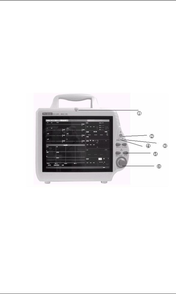
II. Appearance
The POWER switch is on the right quarter of the front panel ( ). The POWER indicator( ) and the BATT indicator ( ) light when the device is powered on. The ALARM indicator flashes or lights when alarm occurs ( ). Sockets for the sensors are on the right side. The recorder socket is on the left side. Other sockets and power plug-in are at the back.
Figure 1-1 Front view of PM-8000 Portable Patient Monitor
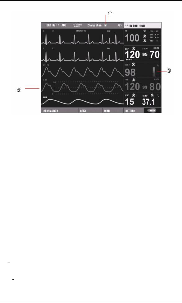
2.1 Screen display
The display of PM-8000 may be color or monochrome liquid crystal. (The monitor of PM-8000 is available in both monochrome and color liquid crystal).Patient parameters, waveforms, alarm messages, bed numbers, date, system status and error messages can be displayed on the screen.
The screen is divided into three areas: ← message area ; ↑ waveform area ; → parameter area
1-2 |
Service Manual of PM-8000 Portable Patient Monitor (V2.0) |
Introduction
Figure 1-2 PM-8000 main screen
Message Area( )
The Message Area is at the top of the screen and used to display operating state of the monitor and status of the patient.
The messages and their meanings are:
BED No |
Bed number of the patient being monitored |
3/1/2001 |
Current date |
10:23:45 |
Current time |
M/F |
Sex of the patient being monitored |
NAME |
name of the patient being monitored. When the user is entering patient name, |
|
the name will be displayed at this position. If no patient name is entered, this |
|
position will be blank. |
Other information in the Message Area comes up only with respective monitoring status. They are:
1.Signs indicating the operating status of the monitor and the sensors are displayed at the right side of time numeric. When appears, this message will cover the sex and name information of the patient.
2.“ ” Indicates that all sounds are disabled manually. It appears when SILENCE button is pressed for more than 1 seconds.
3.“  ” is the sign indicating that the alarm volume is closed. When select the “OFF” option in the ALARM SETUP menu, this mark appears indicating that the operator has permanently closed the
Service Manual of PM-8000 Portable Patient Monitor (V2.0) |
1-3 |

Introduction
audio alarm function. This audio alarm function can resume only after the operator discharges the setup of Close Alarm Volume.
′ NOTE ′
When “ 
 ” sign appears, the system can not give any audio alarm prompt. Therefore, the operator should be careful in using this function. One method of discharging this status is in the ALARM SETUP menu, select the item that the alarm volume is in Non-close. Another method is to press the SILENCE button so as to make the mark change into a
  . Then press SILENCE button again, the system will immediately restores the normal alarm status.
4.Alarm message is displayed always at the extreme right area on the screen.
5.When waveforms on the screen are frozen, “FREEZE” window appears at the bottom of the screen.
Waveform/Menu Area( )
Five waveforms can be displayed at the same time. The waveforms from up to down are: 2 channels of ECG waveforms, SpO2 Plethysmogram, IBP, RESP (possibly coming from ECG module). Waveforms to be displayed are user-selectable. Refer to Tracing Waveforms Selection in Operation Manual for details.
The names of the waveforms are displayed to their left. The names of ECG and IBP are user-selectable. Refer to Chapter ECG/RESP Monitoring and Chapter IBP Monitoring in Operation Manual for details. Gain and filter of this ECG channel are displayed as well. A 1mv scale is marked on the right of ECG waveform. The IBP waveform scale is displayed in IBP wave area. The three dot lines from up to down respectively represent the highest scale, reference scale and lowest scale of the waveform. These values can be manually set. Refer to Chapter IBP Monitoring in Operation Manual for IBP setup.
The same menu always appears at a fixed area on the screen. When the menu is displayed, some waveforms become invisible. The size of the menu is also fixed, covering the lowest 3, 4 or 5 waveforms. If the system exits the menu, the screen will restore its previous look.
The waveforms are refreshed in a user-set rate. Refer to the related chapters for details of sweep speed.
Parameter Area( )
Parameters are displayed at a fixed position ( ~ ). They are (from top to bottom):
1-4 |
Service Manual of PM-8000 Portable Patient Monitor (V2.0) |

Introduction
Figure 1-3 Main Screen
ECG
Heart Rate ( , Unit: bpm)
ST-segment analysis of Channel 1 & 2 ( , Unit: mv)
Arrhythmia (PVCs) events ( , Unit: event/min)
NIBP
(From left to right) Systolic, Mean, Diastolic ( , Unit: mmHg or kPa)
SpO2
SpO2 ( , Unit: %)
IBP
Blood Pressure: Systolic, Mean, and Diastolic values are displayed from left to right. ( , Unit: mmHg or kPa)
RESP
Respiration Rate ( , Unit: breath/min)
TEMP
Temperature ( , Unit: or )
Service Manual of PM-8000 Portable Patient Monitor (V2.0) |
1-5 |
Introduction
The above monitoring results are displayed in the Parameter Area.
The parameters refresh every second, except that the NIBP value refreshes each time when the measurement is over.
User can select the monitor parameters, and the screen display will change accordingly.
Alarm indicator and alarm status:
In normal mode, no indicator lights.
In alarm mode, the alarm indicator lights or flashes. The color of the indicator indicates the alarm level.
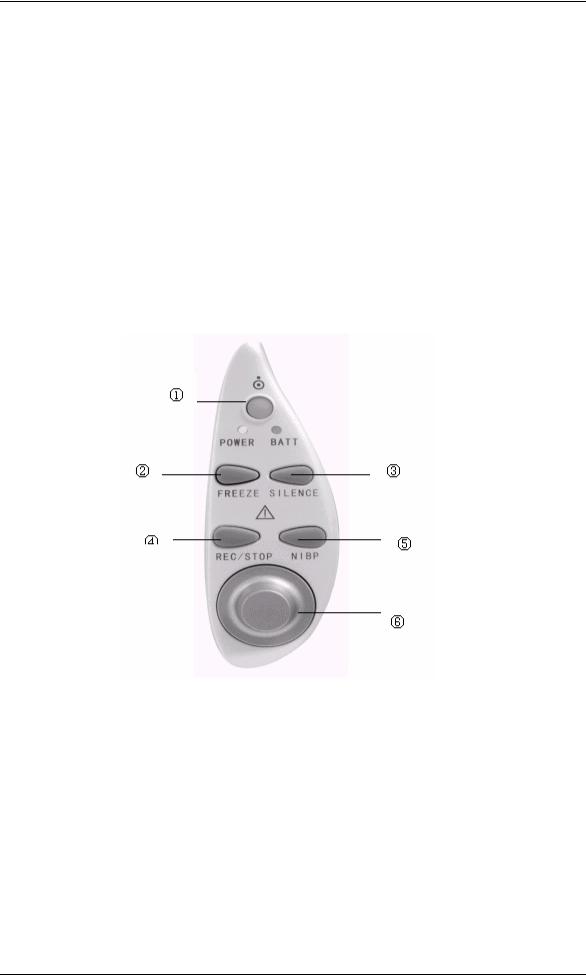
2.2 Button Functions
Figure 1-4 PM-8000 Buttons and Knob
All the operations of PM-8000 can be performed through using the buttons and the rotary knob at the bottom of the screen. Above the buttons are their respective names. They are (from left to right):
Press to turn on/off the monitor.
When in normal mode, press to enter Freeze mode to freeze all the waveforms on the screen. When in Freeze mode, press to restore the waveform refreshing.
Service Manual of PM-8000 Portable Patient Monitor (V2.0)

Introduction
SILENCE
REC/STOP
Press to suspend alarm for 3 minutes (it can be selected in ALARM SETUP menu). Press this button for more than 1 seconds to disable all sound signals
(heart, beat, pulse tone, key sound), and audio alarm. A symbol “ ” displays in the Message Area. Press this key again to restore all sound signals and
remove the “ ” symbol.
NOTE:
If new alarm occurs under Alarm Suspension/Silence state, Suspension/Silence state will change. For specific rules, see Chapter Alarm.
NOTE:
Whether an alarm will be reset depends on the status of the alarm cause. But by pressing SILENCE button can permanently shut off audio sound of the ECG Lead Off and SpO2 Sensor Off alarm.
Press to start a real time recording. The recording time is set in RT REC TIME of RECORD submenu (Refer to related sections for details). Press during recording to stop the recording. When in FREEZE mode, press to select the waveforms for report printout. Refer to Chapter Recording for details.
START
Rotary Knob
Rotary Knob
Press to inflate the cuff to start a blood pressure measurement. When measuring, press to cancel the measurement and deflate the cuff.
This knob can be used to select and change the settings. Operation can be performed by turning it clockwise, counterclockwise or pressing it down.
The square frame that moves when the knob is being turned is called "cursor". Operation can be executed at any place where the cursor can stay. When no menu is displayed, turning the knob clockwise can select following hot keys:
Service Manual of PM-8000 Portable Patient Monitor (V2.0) |
1-7 |

Introduction
Channel 1 ECG lead Channel 1 ECG gain ECG filter
Channel 2 ECG lead Channel 2 ECG gain IBP Label
ECG menu SpO2 menu NIBP menu IBP menu RESP menu TEMP menu
When the current cursor is placed at any of the first six items, the user can change the current settings. When at any of the last six items, related parameter menu could be called up for setting changes.
2 3 Interfaces
For the convenience of operation, different interfaces are in different parts of the monitor. Recorder is on the left side of the monitor while sockets for patient cables and sensors are on the right side. See the figure below:
Figure 1-5 Right side view
1-8 |
Service Manual of PM-8000 Portable Patient Monitor (V2.0) |
Introduction
 This symbol means “BE CAREFUL". Refer to the manual.


 Indicates that the instrument is IEC-60601-1 Type CF equipment. The unit displaying this symbol contains an F-Type isolated (floating) patient applied part providing a high degree of protection against shock, and is suitable for use during defibrillation.
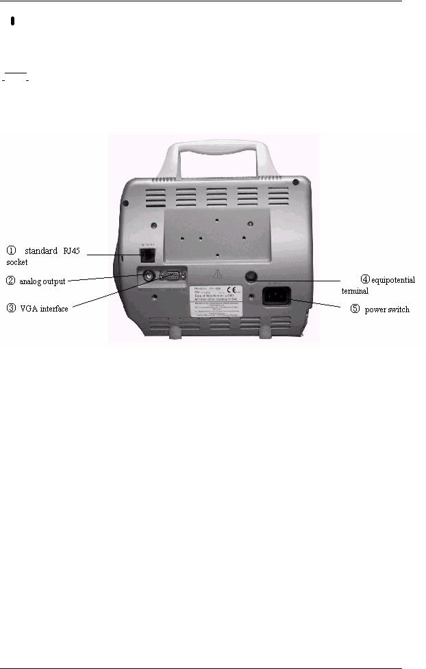
Figure 1-6 Rear panel
Monitor interface for external standard VGA color monitor.
Working mode: |
640 × 480, 16 color, APA mode. |
||
Signal: |
analog R G B |
0.7 Vpp / 750 ohm |
|
|
Hor. / Vert. |
TTL pos. / Neg. |
|
Interface |
D-sub 15 pin |
|
|
|
Pin 1. |
Red Video |
|
|
Pin 2. |
Green Video |
|
|
Pin 3. |
Blue Video |
|
|
Pin 4. |
Ground |
|
|
Pin 5. |
NC |
|
|
Pin 6. |
Red Ground |
|
|
Pin 7. |
Green Ground |
|
|
Pin 8. |
Blue Ground |
|
|
Pin 9. |
NC |
|
|
Pin 10. |
Ground |
|
|
Pin 11. |
NC |
|
Service Manual of PM-8000 Portable Patient Monitor (V2.0) |
1-9 |

Introduction
Pin 12. |
NC |
Pin 13 |
Horizontal Sync. |
Pin 14. |
Vertical Sync. |
Pin 15. |
NC |
Appliance: (Installation) |
|
1)Install the VGA monitor at a place at least 1.5m away from the patient.(The VGA monitor must be installed at least 1.5m away from the patient.)This monitor is used only as an assistant monitoring device.
2)Plug the cable into proper socket before powering on the VGA monitor.
3)It is allowable to power on the VGA monitor and PM-8000 at the same time. Or power on PM-8000 after turning on VGA monitor.
4)Adjust brightness and contrast properly.
(Socket )
Equipotential grounding terminal for connection with the hospital’s grounding system.
ANALOG OUTPUT (Socket )
Analog signal output terminal for connection with oscillometer and pen recorder. The connection terminal is a BNC Jack.
Network Interfaces (Socket ): Standard RJ45 Socket.
 Warning
Through network interface only MINDRAY Clinical Information Center can be connected in.
Warning 
Accessory equipment connected to the analog and digital interfaces must be certified according to the respective IEC standards (e.g. IEC 60950 for data processing equipment and IEC 60601-1 for medical equipment). Furthermore all configurations shall comply with the valid version of the system standard IEC 60601-1-1. Everybody who connects additional equipment to the signal input part or signal output part configures a medical system, and is therefore responsible that the system complies with the requirements of the valid version of the system standard IEC 60601-1-1. If in doubt, consult the technical service department or your local representative.
2 4 Built-in rechargeable battery
PM-8000 Portable Patient Monitor is equipped with a rechargeable battery. The battery in the Monitor can automatically recharge when AC INPUT is connected until it is full. A symbol “


 ” is displayed
1-10 |
Service Manual of PM-8000 Portable Patient Monitor (V2.0) |
Introduction
on the bottom of the screen to indicate the status of recharging, in which the black part represents the relative electric energy of the battery. If the battery is not installed in PM-8000, battery state will be displayed as “ ” to indicate the state. Under the cable socket is the battery slot with cover.
Warning 
Don’t pull off battery when the monitor is working.
When operating on battery, the monitor will prompt alarm and shut off automatically when the energy is low. When the electric energy is going out, the monitor will sound continuous level 1 alarm beeping and display “BATTERY TOO LOW” in the Message Area. Connect the monitor to AC power at this moment can recharge the battery while operating. If keep operating on the battery, the monitor will shut off automatically (about 5 minutes since alarming) upon exhaustion of the battery.
Figure 1-7 Battery slot cover
III. Hardware principle
PM-8000 block diagram
|
TFT D isplay |
|
|
FAN |
|
|
|
|
|
|
|
8.4 inchs |
|
|
|
|
|
|
|
|
|
|
|
|
|
|
|
|
|
|
|
|
|
800 X 600 |
X15 |
|
|
|
|
|
|
|
|
|
X14 |
|
|
|
|
|
|
|
A larm |
|
|
|
|
|
|
|
|
|
|
|
|
|
|
|
|
P1 |
|
|
P5 |
|
|
LE D |
|
|
|
|
P4(TFT_DIGTAL) |
|
|
|
|
J9 |
|
|
|
|
|
|
|
|
K ey & A larm |
P .C .B . |
||
|
J6 |
|
|
P2(CRT) |
|
|
P10 |
J7 |
||
|
|
|
|
|
|
J8 |
||||
|
|
|
|
|
|
|
|
|
|
|
Main |
X16 |
|
|
P3(FOR 9000 VGA) |
|
|
|
|
|
|
P ow erS upply P C B |
J5 |
P7(BDM) |
|
|
S peaker |
|||||
Power |
P12 |
|
|
|
||||||
|
|
|
|
|
||||||
|
|
|
|
|
|
|
|
|
|
|
Input |
J3 |
J2 |
J4 |
P11 |
H ostP .C .B . |
|
|
|
|
|
|
|
|
|
|
|
|
|
|
||
|
|
|
|
|
|
|
X1 |
|
|
|
|
|
|
|
P17(FOR 509C) |
|
P13 |
R ecorderM odule |
|||
|
|
|
|
|
|
|
X2 |
|
||
|
B attery |
|
TO X4 |
P15 |
|
|
|
|
|
|
|
|
|
|
|
|
|
|
|||
|
|
|
|
P16 |
|
|
|
|
|
|
|
|
|
|
P6 |
P9 |
P14 |
P8 |
|
X3 |
|
|
|
|
|
|
|
|
From J2 |
|
X4 R ecorderP .S . |
|
|
|
|
|
|
|
|
|
|
|
|
|
|
|
|
|
|
|
|
|
|
|
|
V G A |
|
|
|
|
|
|
|
|
|
|
|
|
|
|
|
|
|
|
|
|
|
interface |
|
|
|
|
|
|
|
|
|
|
|
|
|
|
|
|
|
|
|
|
|
|
|
|
|
|
|
|
|
|
|
|
|
|
|
|
|
|
|
|
|
|
|
|
|
|
|
|
|
X5 |
|
|
X6 |
|
|
|
X7 |
|
X8 |
|||||
|
|
|
|
|
|
|
E C G / |
|
|
|
|
|
|
|
|||||||
|
|
|
|
|
|
|
|
|
|
|
|
|
|
|
|
|
|
|
|||
|
N E T |
|
|
|
|
|
R E S P / |
|
|
S P O 2 |
|
|
|
N IB P |
|
IB P |
|||||
|
|
|
|
|
|
TE M P |
|
|
P .C .B . |
|
|
M odule |
|
P .C .B . |
|||||||
|
Interface |
|
|
|
|
|
|
|
|
|
|
||||||||||
|
|
|
|
|
|
P .B .C . |
|
|
|
|
|
|
|
|
|
|
|
|
|||
|
|
|
|
|
|
|
|
|
|
|
|
|
|
|
|
|
|
|
|||
|
|
|
|
|
|
|
|
X9 |
|
|
X10 |
|
|
|
X11 |
|
X12 |
||||
|
|
|
|
|
|
|
|
|
|
|
|
|
|
||||||||
|
A nalog |
|
|
|
|
|
PTEM |
|
GCE |
|
|
|
2OPS |
|
|
|
|
PIBN |
|
|
PIB |
|
output |
|
|
|
|
|
|
|
|
|
|
|
|
|
|
|
|
|
|
|
|
|
|
|
|
|
|
|
|
|
|
|
|
|
|
|
|
|
|
|
IBP |
||
|
|
|
|
|
|
|
|
|
|
|
|
|
|
|
|
|
|
|
|
||
|
|
|
|
|
TEMP |
ECG |
|
|
SpO2 |
|
|
|
Cuff |
|
Cable |
||||||
|
|
|
|
|
Sensor |
Cable |
|
|
Sensor |
|
|
|
|
|
|
|
|
||||
Service Manual of PM-8000 Portable Patient Monitor (V2.0) |
1-11 |
Introduction
Figure 1-8 PM-8000 connection diagram
Following are brief description of basic function and operating principle of each part.
3 1 Power board
PM-8000 power board specifications: AC input voltage:100~240VAC AC input current: <1.6A
AC voltage frequency: 50/60HZ
Two-way output voltage: 5V/12V, normal working current is 1.5A for 5V, 2A for 12V. Two-way output voltage has functions of short-circuit, over-current and over-voltage protection. The power board has reset function.
The power board can manage the charging process of lead-acid battery (12V/2.3AH). The charging time is about 6 hours.
Schematic diagram of power board:
5VDC-DC |
|
|
|
|
|
|
|
|
|
BUCK |
|
|
|
|
|
|
Voltage |
|
|
converter |
|
|
|
|
|
|
test |
|
|
|
|
|
|
|
|
|
|
|
|
AC |
AC/DC |
|
input |
||
|
REC POWER
SOURCE Power on/off control circuit
|
|
|
|
|
|
|
|
|
|
Battery |
|
|
|
|
|
|
|
|
|
|
|
|
|
|
|
|
|
|
|
and |
|
|
|
|
|
|
|
|
|
|
|
|
|
|
|
|
|
|
|
Charging |
|
|
|
12V output |
|
|
|
||
Managerent |
|
|
|
|
|
|
|||
|
|
|
|
|
|
||||
|
|
|
|
|
|
|
|
|
|
circuit |
|
|
|
|
|
|
|
|
|
|
|
|
|
|
|
|
|
|
|
Figure 1-9 circuit diagram of PM-8000 power board
Testing key points:
Connect AC power (at this time, the Charge indicator of the battery should light on). Test before power on the monitor.
Use multimeter to measure the DC voltage of the capacitor C12, which should be within the range of 107 ~ 354V.
Use oscillograph to measure between the PIN1 of Q1 and the negative electrode of C12, a driving
1-12 |
Service Manual of PM-8000 Portable Patient Monitor (V2.0) |

Introduction
waveform with the frequency being about 110KHz should exist.
Use multimeter to measure the DC voltage of the capacitor C19, which should be 17.5V.
Use multimeter to measure the DC voltage of the capacitor C24, which should be 13.8V (voltage after removing battery).
Use multimeter to measure the capacitor C47, which should be 5V.
Tests after powering on the monitor:
Use multimeter to measure the regulator ZD3 whose DC voltage should be 5V. Use multimeter to measure the regulator ZD4 whose DC voltage should be 12V. Use multimeter to measure the capacitor C54 whose DC voltage should be 17.2V.
3 2 PM-8000 main control board
Power supply
Input voltage: 12V±5%
5V±5%
The main control board uses the COLDFIRE series embedded microprocessor 5206e manufactured by MOTOROLA Company. It also adopts 3.3V low-voltage power supply to reduce the power consumption. Other main components on the main control board include: Flash, SRAM, FPGA, network controller, etc, all of which require 3.3V power. The capacity of the Flash has been increased to 2MB, which employs two parallel-connected 512Kx16 chips and therefore uses 32-bit character width to support CPU to operate at the highest possible speed instead of accessing to DRAM for operation. The main control board has also a 4MB memory, which is made up of two parallel-connected 1M ×16-bit chips. Because no executing program is required to be loaded, only one RTC is used. This chip uses one 225maH dry cell as the spare power supply. In addition, one 2KB E2PROM is used to store parameters. The main control board supports a resolution of 800x600 and provides three interfaces: a LVDS interface, a 6BIT DIGITAL interface, and a VGA interface. The monitor displays both characters and waveforms in an overlapping way on the whole screen in the same color. The characters and waveforms can be browsed in a scrolling way. The support system needs 10 serial ports, and the baud rate (4800/9600/19.2k/38.4k/76.8k) can be online selected by software and interface buffer drives. The main control board adopts the network controller AX88796 (3.3V, 10MHz), which has inside 16K high-speed buffer SRAM. The MAX5102 8-bit single-way D/A converter is used to fulfil analog output. 5V and 12V stabilized voltage supplies are introduced from the power board, and therefore 3.3V and 2.5V working supplies are respectively generated. Among them, 2.5V is to be used for the internal verification of FPGA.
Service Manual of PM-8000 Portable Patient Monitor (V2.0) |
1-13 |

Introduction
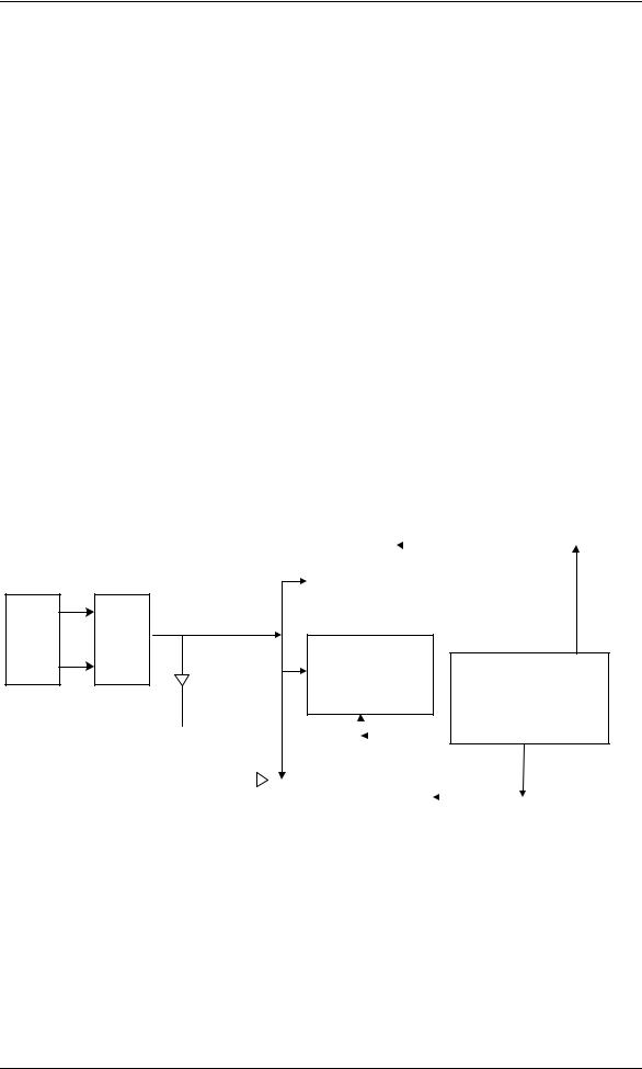
3 3 Structure diagram
RTC/E2PRO |
|
|
|
Flash/ |
M/Watch |
|
DRAM |
|
SRAM |
|
|
|
|
|
Display |
|
CPU |
|
Network |
driving |
|
|
||
circuit |
|
|
|
controller |
|
|
|
|
|
Interrupt |
|
Multi-way |
|
Audio |
|
manageme |
|
|
alarm/spare |
||
nt circuit |
|
serial |
|
battery |
|
|
FPGA |
|
|
|
|
|
|
|
|
|
|
|
|
||||
|
|
|
|||
|
|
|
|
||
|
Figure 1-10 Structure diagram |
|
|||
3 4 Description
3.3V low-voltage power supply component is adopted. The external power is 5V, which is converted by the DC/DC converter into 3.3V and 2.5V, the latter voltage being especially used for FPGA. The main control board are connected with the external devices via following interfaces and input: the power supply connected with the interface board, the 9-way serial port, TFT interface, analog VGA interface, network interface, analog output and a spare serial port, etc. The BDM interface is reserved on the board for the aim of software testing and download.
■ CPU
It use Coldfire5206e. Clock rate is 54MHz, working voltage is 3.3V.
■ FLASH
It use tow parallel-connected 512Kx16 FLASH memories. The output terminal PP1 of CPU is used to realize write-protection of FLASH. It is effective in low-level state.
■ DRAM
PM-8000 main control board uses two parallel-connected 1Mx16 DRAM, which construct 4M address space.
■ Display
The resolution is 800x600. Frequency is 38MHz. It works in an appropriate SVGA mode. VRAM adopts 16-bit structure and is divided into character screen and waveform screen. On the left side of the
1-14 |
Service Manual of PM-8000 Portable Patient Monitor (V2.0) |

Introduction
character screen is the corresponding waveform screen. The right side to the character screen is used to display data and flashing alarms. The user can select color and dot energy. Besides the user can scroll the waveform for clear and complete observation.
■ LVDS interface
Through the way of time-sharing sampling, the LVDS interface converts multi-way CMOS/TTL signals into one-way low-voltage double-frequency difference signals, which are further to be output to the outside). LVDS interface is generally realized by special integrated circuit. The special LVDS chip used for display is DS90CF363A. This chip converts 18-way display pixel signals and 3-way display control signals with a total of 21-way messages into 3-way LVDS signals. Four ways of difference signals including these 3 ways of signals and a way of phase-locked frequency are transmitted to the display screen. On the one side of the screen, these signals are restored for driving the screen. The working frequency of DS90CF363A is 20~65MHz.
■ Reset and parameter storage
The main control board uses an integrated chip CS124C161, which has the functions of both power-on reset and parameter storage. This chip has a E2PROM with the capacity of 2K. It can be used to on-line modify and store various nonvolatile parameters of the host. The power-on reset and WATCHDOG functions are used to realize reset function of the main control board. When J1 is open circuit, the software can also disable WATCHDOG by using the output wire PP0 of CPU in order to realize the selftest of WATCHDOG. The bus interface of this chip is I2C.
■ Data storage
The Main control board uses one non-power-down SRAM having its internal battery to store monitoring data. Its capacity is 2M.
■ Network controller
The network controller adopts special chip AX88796. Its working clock is 25MHz. It also has internal 16K high-speed buffer SRAM. The data bus of this chip is 16-bit width.
Service Manual of PM-8000 Portable Patient Monitor (V2.0) |
1-15 |
Loading...