


SV600
Ventilator
Operator’s Manual


© 2017-2018 Shenzhen Mindray Bio-Medical Electronics Co., Ltd. All rights Reserved.
For this Operator’s Manual, the issue date is December, 2018.
I

Intellectual Property Statement
SHENZHEN MINDRAY BIO-MEDICAL ELECTRONICS CO., LTD. (hereinafter called
Mindray) owns the intellectual property rights to this Mindray product and this manual. This
manual may refer to information protected by copyright or patents and does not convey any
license under the patent rights or copyright of Mindray, or of others.
Mindray intends to maintain the contents of this manual as confidential information.
Disclosure of the information in this manual in any manner whatsoever without the written
permission of Mindray is strictly forbidden. Release, amendment, reproduction, distribution,
rental, adaptation, translation or any other derivative work of this manual in any manner
whatsoever without the written permission of Mindray is strictly forbidden.
, and are the trademarks, registered or otherwise, of
Mindray in China and other countries. All other trademarks that appear in this manual are
used only for informational or editorial purposes. They are the property of their respective
owners.
II

Responsibility on the Manufacturer
Party
Contents of this manual are subject to change without prior notice.
All information contained in this manual is believed to be correct. Mindray shall not be liable
for errors contained herein or for incidental or consequential damages in connection with the
furnishing, performance, or use of this manual.
Mindray is responsible for the effects on safety, reliability and performance of this product,
only if:
all installation operations, expansions, changes, modifications and repairs of this product
are conducted by Mindray authorized personnel;
the electrical installation of the relevant room complies with the applicable national and
local requirements; and
the product is used in accordance with the instructions for use.
WARNING
It is important for the hospital or organization that employs this equipment to
carry out a reasonable service/maintenance plan. Neglect of this may result in
machine breakdown or personal injury.
NOTE
This equipment must be operated by skilled/trained clinical professionals.
III

Warranty
THIS WARRANTY IS EXCLUSIVE AND IS IN LIEU OF ALL OTHER WARRANTIES,
EXPRESSED OR IMPLIED, INCLUDING WARRANTIES OF MERCHANTABILITY OR
FITNESS FOR ANY PARTICULAR PURPOSE.
Exemptions
Mindray's obligation or liability under this warranty does not include any transportation or
other charges or liability for direct, indirect or consequential damages or delay resulting from
the improper use or application of the product or the use of parts or accessories not approved
by Mindray or repairs by people other than Mindray authorized personnel.
This warranty shall not extend to:
Malfunction or damage caused by improper use or man-made failure.
Malfunction or damage caused by unstable or out-of-range power input.
Malfunction or damage caused by force majeure such as fire and earthquake.
Malfunction or damage caused by improper operation or repair by unqualified or
unauthorized service people.
Malfunction of the instrument or part whose serial number is not legible enough.
Others not caused by instrument or part itself.
IV

Customer Service Department
Manufacturer: Shenzhen Mindray Bio-Medical Electronics Co., Ltd.
Address: Mindray Building, Keji 12th Road South, High-tech industrial
park, Nanshan, Shenzhen 518057, P.R. China
Website: www.mindray.com
E-mail Address: service@mindray.com
Tel: +86 755 81888998
Fax: +86 755 26582680
EC-Representative: Shanghai International Holding Corp. GmbH (Europe)
Address: Eiffestraβe 80, 20537 Hamburg, GERMANY
Tel: 0049-40-2513175
Fax: 0049-40-255726
V

Preface
Manual Purpose
This manual contains the instructions necessary to operate the product safely and in
accordance with its function and intended use. Observance of this manual is a prerequisite for
proper product performance and correct operation and ensures patient and operator safety.
This manual is based on the maximum configuration and therefore some contents may not
apply to your product. If you have any question, please contact us.
This manual is an integral part of the product. It should always be kept close to the equipment
so that it can be obtained conveniently when needed.
Intended Audience
This manual is geared for clinical professionals who are expected to have a working
knowledge of medical procedures, practices and terminology as required for monitoring of
critically ill patients.
Illustrations
All illustrations in this manual serve as examples only. They may not necessarily reflect the
setup or data displayed on your ventilator.
Conventions
Italic text is used in this manual to quote the referenced chapters or sections.
[ ] is used to enclose screen texts.
→ is used to indicate operational procedures.
Password
A password is required to access different menus within the ventilator.
System menu: 1234
VI

Table of Contents
1 Safety ................................................................................................................................. 1-1
1.1 Safety Information .......................................................................................................... 1-1
1.1.1 DANGER ........................................................................................................... 1-2
1.1.2 WARNING ......................................................................................................... 1-2
1.1.3 CAUTION .......................................................................................................... 1-6
1.1.4 NOTE ................................................................................................................. 1-8
1.2 Equipment Symbols ........................................................................................................ 1-8
2 The Basics ......................................................................................................................... 2-1
2.1 System Description ......................................................................................................... 2-1
2.1.1 Intended Use....................................................................................................... 2-1
2.1.2 Contraindications ............................................................................................... 2-1
2.1.3 Components ....................................................................................................... 2-1
2.2 Equipment Appearance ................................................................................................... 2-2
2.2.1 Front View .......................................................................................................... 2-2
2.2.2 Rear View ........................................................................................................... 2-4
2.2.3 Air Compressor .................................................................................................. 2-6
3 Installations and Connections ......................................................................................... 3-1
3.1 Connect the Power Supply .............................................................................................. 3-1
3.2 Connect the Pipeline Supply ........................................................................................... 3-2
3.3 Install the Gas Cylinder ................................................................................................... 3-4
3.4 Install the Support Arm ................................................................................................... 3-5
3.5 Install the Patient Tubing ................................................................................................ 3-7
3.5.1 Install Adult/Pediatric Tubing ............................................................................ 3-8
3.5.2 Install Neonate Tubing ....................................................................................... 3-9
3.6 Install the Humidifier ..................................................................................................... 3-11
3.6.1 Install the Humidifier onto the Ventilator .......................................................... 3-11
3.6.2 Install the Humidifier onto the Pendant ........................................................... 3-13
3.7 Install the Nebulizer ...................................................................................................... 3-14
3.7.1 Install Pneumatic Nebulizer ............................................................................. 3-15
3.7.2 Install Electronic Nebulizer .............................................................................. 3-16
3.8 Install the Oxygen Sensor ............................................................................................. 3-17
3.8.1 O
3.8.2 Paramagnetic O
3.9 Install Module ............................................................................................................... 3-19
Cell .............................................................................................................. 3-17
2
Sensor ................................................................................... 3-18
2
4 User Interface ................................................................................................................... 4-1
4.1 Display Controls ............................................................................................................. 4-1
4.2 Waveforms Screen ........................................................................................................... 4-5
1

4.2.1 Graphic trend ...................................................................................................... 4-6
4.2.2 PulmoSight ......................................................................................................... 4-6
4.3 Spirometry Screen ........................................................................................................... 4-7
4.4 Measured Values Screen ................................................................................................ 4-10
4.5 Big Numeric Interface ................................................................................................... 4-10
4.6 History ............................................................................................................................ 4-11
4.6.1 Graphic Trend.................................................................................................... 4-11
4.6.2 Tabular Trend ................................................................................................... 4-13
4.6.3 Setting Trends................................................................................................... 4-14
4.6.4 Event Logbook ................................................................................................. 4-15
4.7 Freeze ............................................................................................................................ 4-16
4.7.1 Enter Freeze Status ........................................................................................... 4-16
4.7.2 View Frozen Waveforms .................................................................................. 4-16
4.7.3 View Frozen Loop ............................................................................................ 4-17
4.7.4 Exit Freeze Status ............................................................................................. 4-17
4.8 Screen Capture .............................................................................................................. 4-18
4.9 Lock Screen ................................................................................................................... 4-18
5 System Settings ................................................................................................................. 5-1
5.1 Date & Time Settings ...................................................................................................... 5-1
5.2 Export to USB ................................................................................................................. 5-1
5.2.1 Export Screen ..................................................................................................... 5-1
5.2.2 Export Data ........................................................................................................ 5-1
5.2.3 Transfer Settings ................................................................................................. 5-2
5.3 Basic Settings .................................................................................................................. 5-3
5.3.1 Set Flow/Tpause(%) ........................................................................................... 5-3
5.3.2 Set Tinsp/I:E ....................................................................................................... 5-3
5.3.3 Set IBW/Height .................................................................................................. 5-3
5.3.4 Set TV/IBW ....................................................................................................... 5-4
5.3.5 Setup DuoLevel .................................................................................................. 5-4
5.3.6 Set Invasive Apnea Mode ................................................................................... 5-4
5.3.7 Set O
% increment during O2↑ period ............................................................ 5-4
2
5.3.8 Set Oxygen Sensor Monitoring .......................................................................... 5-5
5.4 Screen Settings ................................................................................................................ 5-6
5.4.1 Adjust Screen Brightness ................................................................................... 5-6
5.4.2 Adjust Key Volume ............................................................................................ 5-6
5.4.3 Screen Setup ....................................................................................................... 5-6
5.4.4 Color Settings ..................................................................................................... 5-7
5.5 System Settings ............................................................................................................... 5-8
5.5.1 Set Language ...................................................................................................... 5-8
5.5.2 Set Unit .............................................................................................................. 5-8
5.5.3 Set Minimum Alarm Volume ............................................................................. 5-8
5.5.4 Default Settings .................................................................................................. 5-9
5.5.5 Set Nurse Call .................................................................................................. 5-10
2

5.5.6 Set Network ...................................................................................................... 5-10
5.5.7 View System Information ................................................................................. 5-10
5.6 Set Tool Shortcut Key .................................................................................................... 5-11
5.7 Set Gas Supply ............................................................................................................... 5-11
5.8 Factory Service Settings ................................................................................................. 5-11
6 Start Ventilation ................................................................................................................ 6-1
6.1 Turn on the System ......................................................................................................... 6-1
6.2 System Check .................................................................................................................. 6-1
6.3 Circuit Test ...................................................................................................................... 6-3
6.4 Select Patient ................................................................................................................... 6-5
6.4.1 Set Patient Information on the Ventilator ........................................................... 6-5
6.4.2 Getting Patient Information from the ADT Server ............................................. 6-5
6.5 Ventilation Type .............................................................................................................. 6-6
6.5.1 Invasive Ventilation ............................................................................................ 6-6
6.5.2 Non-Invasive Ventilation (NIV) ......................................................................... 6-7
6.5.3 Set Ventilation Type ........................................................................................... 6-7
6.6 Ventilation Mode ............................................................................................................. 6-8
6.6.1 Ventilation Mode and Parameter Setup .............................................................. 6-8
6.6.2 V-A/C ............................................................................................................... 6-10
6.6.3 P-A/C ................................................................................................................ 6-11
6.6.4 V-SIMV ............................................................................................................ 6-12
6.6.5 P-SIMV ............................................................................................................ 6-13
6.6.6 CPAP/PSV ........................................................................................................ 6-14
6.6.7 PSV-S/T ............................................................................................................ 6-16
6.6.8 PRVC ................................................................................................................ 6-17
6.6.9 PRVC-SIMV .................................................................................................... 6-18
6.6.10 DuoLevel ........................................................................................................ 6-20
6.6.11 APRV .............................................................................................................. 6-21
6.6.12 VS ................................................................................................................... 6-22
6.6.13 AMV ............................................................................................................... 6-23
6.6.14 CPRV .............................................................................................................. 6-25
6.6.15 nCPAP ............................................................................................................ 6-26
6.6.16 Apnea Ventilation ........................................................................................... 6-27
6.7 Other Ventilation Settings ............................................................................................. 6-28
6.7.1 Sigh .................................................................................................................. 6-28
6.7.2 Leak Compensation .......................................................................................... 6-29
6.7.3 Automatic Tube Resistance Compensation (ATRC) ........................................ 6-31
6.7.4 IntelliCycle ....................................................................................................... 6-32
6.8 Alarm settings ............................................................................................................... 6-32
6.9 Start Ventilation ............................................................................................................. 6-32
6.10 Ventilation Parameters................................................................................................. 6-33
6.11 Enter Standby Status ................................................................................................... 6-37
6.12 Turn the System off ..................................................................................................... 6-37
3

7 Neonatal Ventilation ......................................................................................................... 7-1
7.1 Safety Information .......................................................................................................... 7-1
7.2 Connecting Patient Tubing to the Flow Sensor ............................................................... 7-2
7.3 Circuit Test ...................................................................................................................... 7-2
7.4 Start Ventilation ............................................................................................................... 7-2
7.5 Backup Ventilation .......................................................................................................... 7-3
7.6 Set the Monitoring Switch .............................................................................................. 7-3
7.7 Neonatal Flow Sensor Zeroing ........................................................................................ 7-3
8 CO
Monitoring ................................................................................................................ 8-1
2
8.1 Introduction ..................................................................................................................... 8-1
8.2 CO2 Module .................................................................................................................... 8-4
8.3 Sidestream CO
Module .................................................................................................. 8-5
2
8.3.1 Preparation for Measurement ............................................................................. 8-5
8.3.2 Make CO
Settings ............................................................................................. 8-6
2
8.3.3 Measurement Limitations ................................................................................... 8-8
8.3.4 Troubleshooting .................................................................................................. 8-8
8.3.5 Zero the Sensor .................................................................................................. 8-8
8.3.6 Calibrate the Sensor ........................................................................................... 8-8
8.4 Mainstream CO
module ................................................................................................. 8-9
2
8.4.1 Preparation for Measurement ............................................................................. 8-9
8.4.2 Make CO
Settings ........................................................................................... 8-10
2
8.4.3 Measurement Limitations .................................................................................. 8-11
8.4.4 Zero the Sensor ................................................................................................. 8-11
8.4.5 Calibrate the Sensor ......................................................................................... 8-12
9 SpO2 Monitoring .............................................................................................................. 9-1
9.1 Introduction ..................................................................................................................... 9-1
9.2 Safety Information .......................................................................................................... 9-2
9.3 Applying the Sensor ........................................................................................................ 9-3
9.4 Make SpO
9.4.1 Set SpO
Settings ........................................................................................................ 9-3
2
Monitoring .......................................................................................... 9-3
2
9.4.2 Set Sensitivity..................................................................................................... 9-3
9.4.3 Beat Volume ....................................................................................................... 9-3
9.4.4 Set CO
Waveform ............................................................................................. 9-3
2
9.5 Measurement Limitations ................................................................................................ 9-4
10 Special Functions .......................................................................................................... 10-1
10.1 Manual Breath ............................................................................................................. 10-1
10.2 Expiration Hold ........................................................................................................... 10-1
10.3 Inspiration Hold .......................................................................................................... 10-2
10.4 Nebulizer ..................................................................................................................... 10-2
10.4.1 Pneumatic Nebulizer ...................................................................................... 10-3
10.4.2 Electronic Nebulizer ....................................................................................... 10-3
4

10.5 O2↑(Oxygen Enrichment) .......................................................................................... 10-4
10.6 Suction ........................................................................................................................ 10-5
10.7 P0.1 ............................................................................................................................. 10-6
10.8 PEEPi .......................................................................................................................... 10-6
10.9 NIF .............................................................................................................................. 10-7
10.10 Calculation of Alveolar Ventilation ........................................................................... 10-7
10.11 P-V Tool .................................................................................................................... 10-8
10.12 Recruitment Tool(SI) ......................................................................................... 10-10
10.12.1 History ......................................................................................................... 10-11
10.13 Weaning Tools .......................................................................................................... 10-11
10.13.1 Help Information Viewing.......................................................................... 10-12
10.13.2 Spontaneous Breathing Trial (SBT) ........................................................... 10-12
10.13.3 History ........................................................................................................ 10-13
10.14 O
Therapy .............................................................................................................. 10-14
2
10.14.1 Preparing for O
10.14.2 Switching on O
10.14.3 O
Therapy Timing/Timer .......................................................................... 10-18
2
10.14.4 Switching off O
Therapy ........................................................................... 10-14
2
Therapy ........................................................................... 10-17
2
Therapy ........................................................................... 10-18
2
11 Alarms ............................................................................................................................ 11-1
11.1 Introduction .................................................................................................................. 11-1
11.2 Alarm Categories .......................................................................................................... 11-2
11.3 Alarm Priority Levels ................................................................................................... 11-2
11.4 Alarm Signals ............................................................................................................... 11-2
11.4.1 Alarm Lamp ..................................................................................................... 11-3
11.4.2 Audible Alarm ................................................................................................. 11-3
11.4.3 Alarm Messages .............................................................................................. 11-3
11.4.4 Flashing Alarm Numeric ................................................................................. 11-3
11.4.5 Alarm Status Symbol ....................................................................................... 11-4
11.5 Alarm Volume Settings ................................................................................................. 11-4
11.6 Set Alarm Limits .......................................................................................................... 11-5
11.6.1 Auto Alarm Limits ........................................................................................... 11-5
11.7 AUDIO PAUSED ......................................................................................................... 11-6
11.7.1 Set AUDIO PAUSED ...................................................................................... 11-6
11.7.2 Terminate AUDIO PAUSED ........................................................................... 11-6
11.8 Current Alarm ............................................................................................................... 11-7
11.9 Alarm Chain ................................................................................................................. 11-8
11.10 Recent Alarm .............................................................................................................. 11-8
11.11 ALARM OFF ............................................................................................................. 11-9
11.12 Alarm Tests ............................................................................................................... 11-10
11.12.1 Battery in Use .............................................................................................. 11-10
11.12.2 Loss of Power .............................................................................................. 11-10
11.12.3 Paw Too High .............................................................................................. 11-10
11.12.4 Paw Too Low ............................................................................................... 11-11
5

11.12.5 TVe Too Low ............................................................................................... 11-11
11.12.6 TVe Too High .............................................................................................. 11-11
11.12.7 MV Too Low ............................................................................................... 11-11
11.12.8 Air Supply Pressure Low ............................................................................. 11-11
11.12.9 O
Supply Pressure Low .............................................................................. 11-12
2
11.12.10 PEEP Too Low .......................................................................................... 11-12
11.12.11 Airway Obstructed ..................................................................................... 11-12
11.12.12 FiO
11.12.13 FiO
11.12.14 EtCO
11.12.15 EtCO
11.12.16 SpO
11.12.17 SpO
11.12.18 SpO
Too High ........................................................................................... 11-12
2
Too Low ............................................................................................ 11-13
2
Too High ........................................................................................ 11-13
2
Too Low ......................................................................................... 11-13
2
Too High .......................................................................................... 11-13
2
Too Low ........................................................................................... 11-14
2
Desat ................................................................................................ 11-14
2
11.12.19 PR Too High .............................................................................................. 11-14
11.12.20 PR Too LOW ............................................................................................. 11-14
11.13 Nurse Call ................................................................................................................. 11-15
11.14 When an Alarm Occurs ............................................................................................ 11-16
12 Cleaning and Disinfection ............................................................................................ 12-1
12.1 Methods for Cleaning and Disinfection ...................................................................... 12-2
12.2 Disassemble the Ventilator’s Cleanable and Disinfectable Parts ................................ 12-5
12.2.1 Expiration Valve Assembly and Membrane ................................................... 12-5
12.2.2 Inspiration safety valve assembly .................................................................. 12-7
12.2.3 HEPA Filter Components and Air Intake Dust Filter ................................... 12-10
12.2.4 Back air supply cooling fan dust filter ......................................................... 12-12
12.2.5 Main Unit Air Outlet Dust Filter .................................................................. 12-13
12.2.6 Patient Tubing .............................................................................................. 12-14
12.2.7 Humidifier .................................................................................................... 12-16
12.2.8 Nebulizer ...................................................................................................... 12-19
12.2.9 Mainstream CO
Module ............................................................................. 12-22
2
13 Maintenance ................................................................................................................. 13-1
13.1 Repair Policy ............................................................................................................... 13-1
13.2 Maintenance Schedule ................................................................................................ 13-2
13.3 View Preventive Maintenance Items ........................................................................... 13-4
13.4 Pressure and Flow Zeroing .......................................................................................... 13-5
13.5 Neonatal Flow Sensor Zeroing .................................................................................... 13-5
13.6 Flow Calibration ......................................................................................................... 13-6
13.7 O
13.8 CO
% Calibration .......................................................................................................... 13-7
2
Calibration ........................................................................................................... 13-8
2
13.8.1 Sidestream CO
13.8.2 Mainstream CO
Module ................................................................................. 13-8
2
Module ............................................................................... 13-9
2
13.9 Touch Screen Calibration ............................................................................................ 13-9
6

13.10 Battery Maintenance ................................................................................................. 13-9
13.10.1 Battery Guidelines ....................................................................................... 13-11
13.10.2 Battery Performance Conditioning .............................................................. 13-11
13.10.3 Battery Performance Checking .................................................................. 13-12
13.10.4 Battery Storage ........................................................................................... 13-12
13.10.5 Battery Recycling ....................................................................................... 13-13
13.11 Electrical Safety Inspection ..................................................................................... 13-13
13.12 Water Build-up in the Flow Sensor ......................................................................... 13-15
13.12.1 Prevent Water Build-up .............................................................................. 13-15
13.12.2 Clear Water Build-up .................................................................................. 13-15
14 Accessories .................................................................................................................... 14-1
A Theory of Operation ....................................................................................................... A-1
A.1 Pneumatic Circuit Principle .......................................................................................... A-1
A.1.1 Pneumatic Circuit Diagram .............................................................................. A-1
A.1.2 Parts List ........................................................................................................... A-2
A.1.3 Definition of Symbols ...................................................................................... A-3
A.1.4 Pneumatic System Overview ............................................................................ A-4
A.2 Electrical System ........................................................................................................... A-7
A.2.1 Electrical System Structure Diagram ............................................................... A-7
A.2.2 Parts List ........................................................................................................... A-8
B Product Specifications ..................................................................................................... B-1
B.1 Safety Specifications ...................................................................................................... B-1
B.2 Environmental Specifications ......................................................................................... B-2
B.3 Power Requirements ....................................................................................................... B-3
B.4 Physical Specifications ................................................................................................... B-4
B.5 Pneumatic System Specifications ................................................................................... B-5
B.6 Ventilator Specifications ................................................................................................. B-7
B.7 Ventilator Accuracy ...................................................................................................... B-10
B.8 Alarm ............................................................................................................................ B-12
B.8.1 Settable Alarms ................................................................................................ B-12
B.8.2 Internal Alarms ................................................................................................ B-13
B.9 Special Function ........................................................................................................... B-13
B.10 CO
B.11 SpO
Module Specifications ........................................................................................ B-14
2
B.10.1 Sidestream CO
B.10.2 Mainstream CO
Module Specifications ....................................................................................... B-16
2
Module ................................................................................ B-14
2
Module ............................................................................... B-15
2
B.12 Air Compressor Specification ..................................................................................... B-18
B.13 Backup Air Supply ..................................................................................................... B-18
C EMC ................................................................................................................................ C-1
7

D Alarm Messages .............................................................................................................. D-1
D.1 Physiological Alarm Messages ...................................................................................... D-1
D.1.1 Ventilator Parameters ....................................................................................... D-1
D.1.2 CO
D.1.3 SpO
Module...................................................................................................... D-2
2
Module .................................................................................................... D-3
2
D.2 Technical Alarm Messages ............................................................................................ D-4
D.2.1 Power Board ..................................................................................................... D-4
D.2.2 Main Control Board ......................................................................................... D-5
D.2.3 Monitor Board .................................................................................................. D-5
D.2.4 CO
D.2.5 SpO
Module...................................................................................................... D-9
2
Module .................................................................................................. D-10
2
D.2.6 Neo. Module .................................................................................................... D-11
E Factory Defaults .............................................................................................................. E-1
E.1 Ventilation Parameters .................................................................................................... E-1
E.2 Setup ............................................................................................................................... E-2
E.3 SystemSettings ................................................................................................................ E-3
E.4 Alarms ............................................................................................................................. E-3
E.5 History ............................................................................................................................ E-4
E.6 Special Functions ............................................................................................................ E-4
E.7 O
Therapy ...................................................................................................................... E-5
2
E.8 CO
E.9 SpO
Module .................................................................................................................... E-6
2
Module .................................................................................................................. E-6
2
E.10 Other ............................................................................................................................. E-6
F Symbols and Abbreviations ............................................................................................. F-1
F.1 Unit .................................................................................................................................. F-1
F.2 Symbols ........................................................................................................................... F-2
F.3 Abbreviations .................................................................................................................. F-2
8
1 Safety
1.1 Safety Information
DANGER
Indicates an imminent hazard that, if not avoided, will result in death or serious
injury.
WARNING
Indicates a potential hazard or unsafe practice that, if not avoided, could result in
death or serious injury.
CAUTION
Indicates a potential hazard or unsafe practice that, if not avoided, could result in
minor personal injury and/or product/property damage.
NOTE
Provides application tips or other useful information to ensure that you get the
most from your product.
1-1

1.1.1 DANGER
There are no dangers that refer to the product in general.
1.1.2 WARNING
WARNING
The ventilator must only be operated and used by authorized medical personnel
well trained in the use of this product. Any unauthorized or untrained personnel
should not perform any operations. It must be operated strictly following the
Operator’s Manual.
Before putting the system into operation, the operator must verify that the
equipment, connecting cables and accessories are in correct working order and
operating condition.
To avoid the risk of electric shock, this equipment must be connected to a properly
installed power outlet with protective earth contacts only. If the installation does
not provide for a protective earth conductor, disconnect it from the power line. In
this case, lithium ion batteries should be used temporarily to supply power to the
equipment.
Use external power source (AC power) before the batteries are depleted.
To avoid explosion hazard, do not use the equipment in the presence of flammable
anesthetic agent, vapors or liquids. When O
any fire sources.
Do not place the ventilator adjacent to any barrier, which can prevent cold air
from flowing, resulting in equipment overheat.
Do not open the case of the equipment, as you may suffer an electric shock. All
servicing and future upgrades must be carried out by the personnel trained and
authorized by us only.
Users should set alarm volume and alarm limits based on patients’ actual
condition. Do not rely exclusively on the audible alarm system for patient
monitoring. Adjustment of alarm volume to a low level may result in a hazard to
the patient. Always keep the patient under close surveillance.
The physiological parameters and alarm messages displayed on the screen of the
equipment are for doctor’s reference only and cannot be directly used as the basis
for clinical treatment.
To dispose of the package material, observe the applicable waste control
regulations. And keep the package material out of children’s reach.
is used, keep the ventilator away from
2
All staff should be aware that disassembling or cleaning some parts of the
ventilator can cause risk of infection.
1-2

WARNING
Maintenance menu can only be accessed when the equipment is disconnected from
the patient.
Positive pressure ventilation may be accompanied by some side effects such as
barotrauma, hypoventilation, hyperventilation, etc.
Using high frequency electrosurgery equipment, defibrillators, or short-wave
treatment equipment in the vicinity of the ventilator may interfere with its
operation and pose a risk of patient injury.
Do not use antistatic or conductive masks or patient tubing. They can cause burns
if they are used near high frequency electrosurgery equipment.
Do not use the ventilator in a hyperbaric chamber.
If the equipment internal monitoring system malfunctions, an alternative plan
must be available to ensure adequate level of monitoring. The operator of the
ventilator must be responsible for patient’s proper ventilation and safety under all
circumstances.
As required by the relevant rules and regulations, oxygen concentration should be
monitored when the equipment is used on the patient. If your ventilator is not
configured with such monitoring function or this function is turned off, use a
monitor which complies with the requirements of ISO 80601-2-55 for oxygen
concentration monitoring.
All analog or digital products connected to this system must be certified to the
specified IEC standards (such as IEC 60950 for data processing equipment and
IEC 60601-1 for medical electrical equipment). All configurations shall comply
with the valid version of IEC 60601-1. The personnel who are responsible for
connecting the optional equipment to the I/O signal port shall be responsible for
medical system configuration and system compliance with IEC 60601-1 as well.
Do not touch the patient when connecting the peripheral equipment via the I/O
signal ports or replacing the O
cell, to prevent patient leakage current from
2
exceeding the requirements specified by the standard.
This equipment is not suitable for use in an MRI environment.
When the ventilator’s gas supply input system fails or has faults, please contact us
immediately for service by specified personnel.
The ventilator shall not be used with helium or mixtures with Helium.
Do not move the ventilator before removing the support arm from it, in order to
avoid the ventilator getting tilted during the movement.
The oxygen and air gas mixer of the ventilator is without grease and thus no
de-grease process is needed. Do not use lubricants that contain oil or grease, and
rubber hose assembly should not be contaminated with grease. Lubricants will
burn or explode when exposed to high O
concentrations.
2
1-3

WARNING
The maximum pressure of hose is 1.4MPa@21℃ and please check whether gas
supply pressure meets hose requirements before usage.
Hose connectors adopt standardized gas terminal connector with gas nature.
Different types of gas and gas with different pressures shall not be exchanged with
each other.
Hose may be aging quickly by long-term exposure to acidity, alkalinity or
ultraviolet rays.
Don’t cascade two or more hose assemblies together.
The ventilator arm could bear 1kg maximally and don’t hang over 1kg goods.
After the ventilator is installed or the main control board is replaced, the altitude
must be reset. After resetting the altitude value, please perform flow calibration
(factory).
When disconnecting fast connectors, please operate by two hands to prevent
potential injury caused by sudden pressure release.
Do not block the air intake on the side of the ventilator.
To prevent interrupted operation of the ventilator due to electromagnetic
interference, avoid using the ventilator adjacent to or stack with other device. If
adjacent or stacked use is necessary, verify the ventilator’s normal operation in the
configuration in which it will be used.
To prevent possible personal injury and equipment damage, ensure that the
ventilator is secured to the trolley or placed on the safe and smooth surface.
To prevent possible equipment damage, avoid tipping over the ventilator when
crossing thresholds.
To prevent possible equipment damage, push the brake down when parking the
ventilator.
Avoid the use of polluted air. When the equipment uses air as gas source for
ventilation, if the air is polluted, harmful substance may enter the patient tubing.
To prevent patient injury caused by equipment malfunction, when the alarm
[Technical Error**] occurs, remove the equipment immediately, record failure
code, and contact the Customer Service Department.
To prevent possible ventilator malfunction, do not spill liquid onto the ventilator.
Backup air supply could cause gas to be heated. To reduce the temperature of gas
inside the tubing and prevent patient injury accordingly, ensure that the length of
patient tubing from the humidifier to Y piece is greater than 1.2m.
The internal electrical power source is to be used temporarily if the integrity of the
protective earth conductor or the protective grounding system in the installation is
in doubt.
1-4

WARNING
Nebulization or humidification can increase the resistance of breathing system
filters, and that you need to monitor the filter frequently for increased resistance
and blockage.
The ventilation accuracy can be affected by the gas added by use of a nebulizer.
The ventilator shall not be used with nitric oxide.
Check if the alarm limit settings are appropriate before taking measurement.
When operating the unit with the power supply unit, always connect the unit to an
easily accessible outlet so that it can be unplugged quickly in the event of a
malfunction.
No modification of this equipment is allowed.
Stop using the ventilator and contact us immediately when the buzzer sounds.
Please place cables of neonatal flow sensor correctly, to avoid patients from
becoming entangled or unplanned extubation.
System leakage, such as leakage caused by an uncuffed endotracheal tube, may
influence airflow readings, including airflow parameters, pressure, dead space, and
CO
production.
2
When ventilator is connected to patient, do not remove or replace fuse, or perform
any other maintenance tasks. Such tasks must be performed when the patient is not
using the ventilator.
Please ensure that the AC power cord is disconnected before removing or replacing
the fuse.
HAZARD can exist if different ALARM PRESETS are used for the same or
similar equipment in any single area. Please read the manual and confirm the
correct alarm pre-settings for the ventilator before using it.
1-5

1.1.3 CAUTION
CAUTION
The ventilator must be inspected and serviced regularly by trained service
personnel.
To ensure patient safety, always prepare resuscitator for use.
Always have a special person attend and monitor the operation of the equipment
once the ventilator is connected to the patient.
During the operation of the ventilator, do not disassemble the inspiration safety
valve and expiration valve unless in standby status.
To ensure patient safety, use only parts and accessories specified in this manual.
At the end of its service life, the equipment, as well as its accessories, must be
disposed of in compliance with the guidelines regulating the disposal of such
products.
Magnetic and electrical fields are capable of interfering with the proper
performance of the equipment. For this reason, ensure that all external devices
operated in the vicinity of the equipment comply with the relevant EMC
requirements. Mobile phone, X-ray equipment or MRI devices are a possible
source of interference as they may emit higher levels of electromagnetic radiation.
This system operates correctly at the electrical interference levels identified in this
manual. Higher levels can cause nuisance alarms that may stop mechanical
ventilation. Pay attention to false alarms caused by high-intensity electrical fields.
Before connecting the equipment to the power line, check that the voltage and
frequency ratings of the power line are the same as those indicated on the
equipment’s label or specified in this manual.
Always install or carry the equipment properly to avoid damage caused by
dropping down, impact, strong vibration or other mechanical force.
Check whether the repetitive patient tubing is damaged or leaked before usage. If
so, don’t use such tubing.
To electrically isolate the ventilator circuits from all poles of the supply mains
simultaneously, disconnect the mains plug.
To minimize the risk of fire, do not use supply hose assembly that is worn or
contaminated with combustible materials like grease or oil.
It is the clinician’s responsibility to ensure that all ventilator settings are
appropriate.
To prevent possible patient injury, ensure the ventilator is set up for appropriate
patient type with the appropriate patient tubing. Ensure that the System Check or
1-6

CAUTION
tubing check is performed before each patient.
Perform Flow Sensor Calibration before the first use, or when the measured values
have deviations.
To prevent possible patient injury, ensure the ventilation parameters are set up
properly before ventilating the patient.
To ensure the accuracy of oxygen monitoring, replace an exhausted O
cell as soon
2
as possible or use an external monitor that complies with ISO 80601-2-55.
A fan failure could result in oxygen enrichment inside the ventilator and a
subsequent fire hazard.
To reduce the risk of explosion, do not force the chemical O
cell open or place it
2
close to a source of heat.
When ventilating with a mask, avoid high airway pressures. High pressures may
cause gastric distension.
Peak pressures exceeding 33 cmH
O may increase the risk of gastric insufflation
2
when the ventilation type is non-invasive. When ventilating with such pressures,
consider using an invasive mode.
To reduce the risk of fire, use only tube systems approved for medical purposes
and for use with oxygen between the oxygen source and ventilator.
To reduce the risk of fire, ensure adequate ventilation at the rear of the ventilator.
To reduce the risk of fire, switch off the oxygen source when the ventilator is not in
a ventilating mode.
Avoid putting the ventilator in the storage environment of more than 50℃ for a
long time. Such environment may damage or shorten the battery lives of internal
battery and O
cell.
2
Use the original packing materials to ship the ventilator.
To prevent fire hazard, use only specified fuses or fuses with the same type, rated
voltage, and rated current as the existing fuses. When it is necessary to replace
fuses, contact the Customer Service Department.
The ventilator is suitable for use within the PATIENT ENVIRONMENT.
Additional MULTIPLE SOCKET- OUTLET or extension cord shall not be
connected to the system.
Before moving the ventilator, ensure that the casters and brakes can work
properly, and the main unit is locked on the trolley.
Please use dry and clean medical compressed air and oxygen as gas supply. Water
in gas supply can cause equipment malfunction.
1-7
1.1.4 NOTE
NOTE
Put the ventilator and its accessories in a location where you can easily see the
screen and access the operating controls.
Keep this manual close to the equipment so that it can be obtained conveniently
when needed.
The software was developed in compliance with IEC 62304. The possibility of
hazards arising from software errors is minimized.
This manual describes all features and options. Your equipment may not have all
of them.
When the oxygen supply is insufficient, the ventilator will automatically switch to
air supply. When the air supply is insufficient, the ventilator will automatically
switch to oxygen supply.
The ventilator is equipped with barometric pressure sensors, and has the function
of barometric pressure compensation.
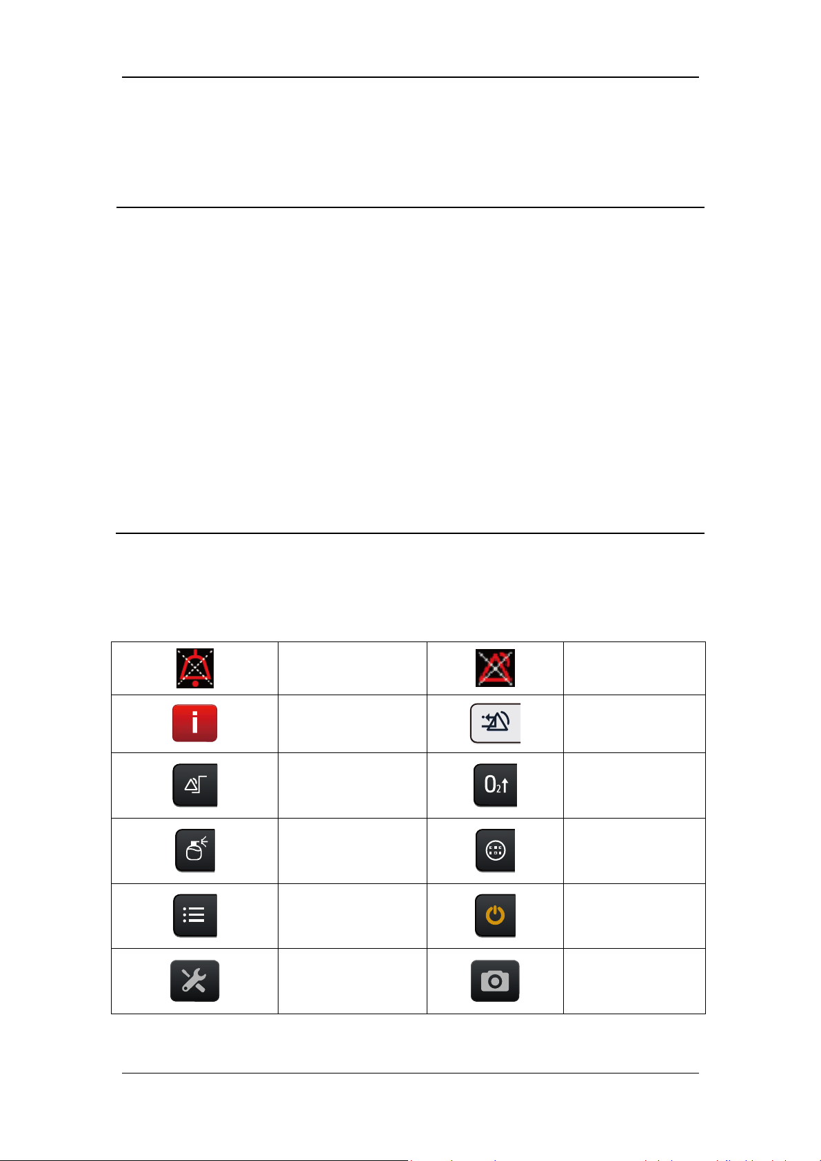
1.2 Equipment Symbols
AUDIO PAUSED
Recent Alarm
Alarm settings
Nebulizer
ALARM OFF
Clear alarm
O2↑key
Tools key
Setup
Preventive
maintenance
Standby key
Screen Capture
1-8
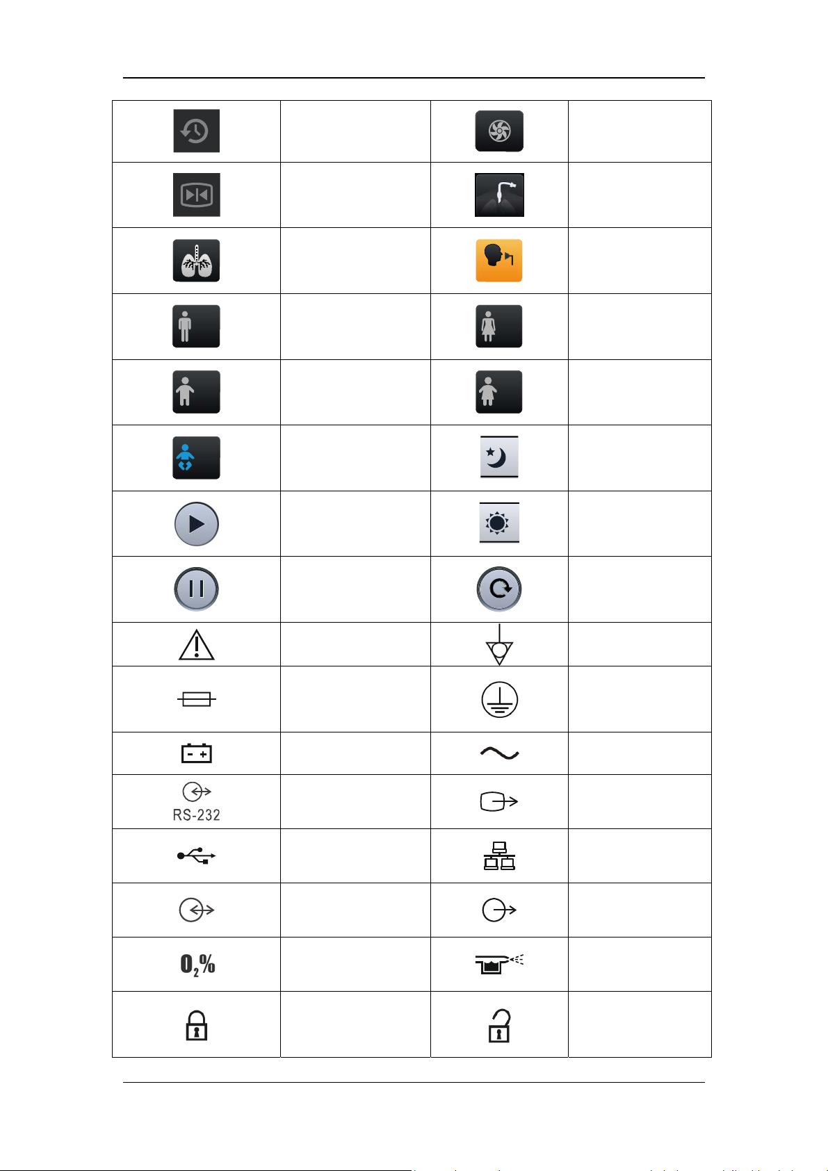
History
Freeze
Inspiratory trigger
icon
Adult (male)
Pediatric (male)
Backup Air Supply
Invasive Ventilation
Non-Invasive
Ventilation
Adult (female)
Pediatric (female)
Adjust screen
Neonate
brightness/volume to
night mode
Adjust screen
Start O2 therapy timer
brightness/volume to
day mode
Stop O2 therapy timer
Caution
Fuse
Battery LED
RS-232 connector
USB connector
Display connector
Oxygen sensor
connector
Reset O2 therapy
timer
Equipotentiality
Protective earth
ground
AC power
VGA output
connector
Network connector
Nurse call connector
Pneumatic nebulizer
connector
Lock
Unlock
1-9
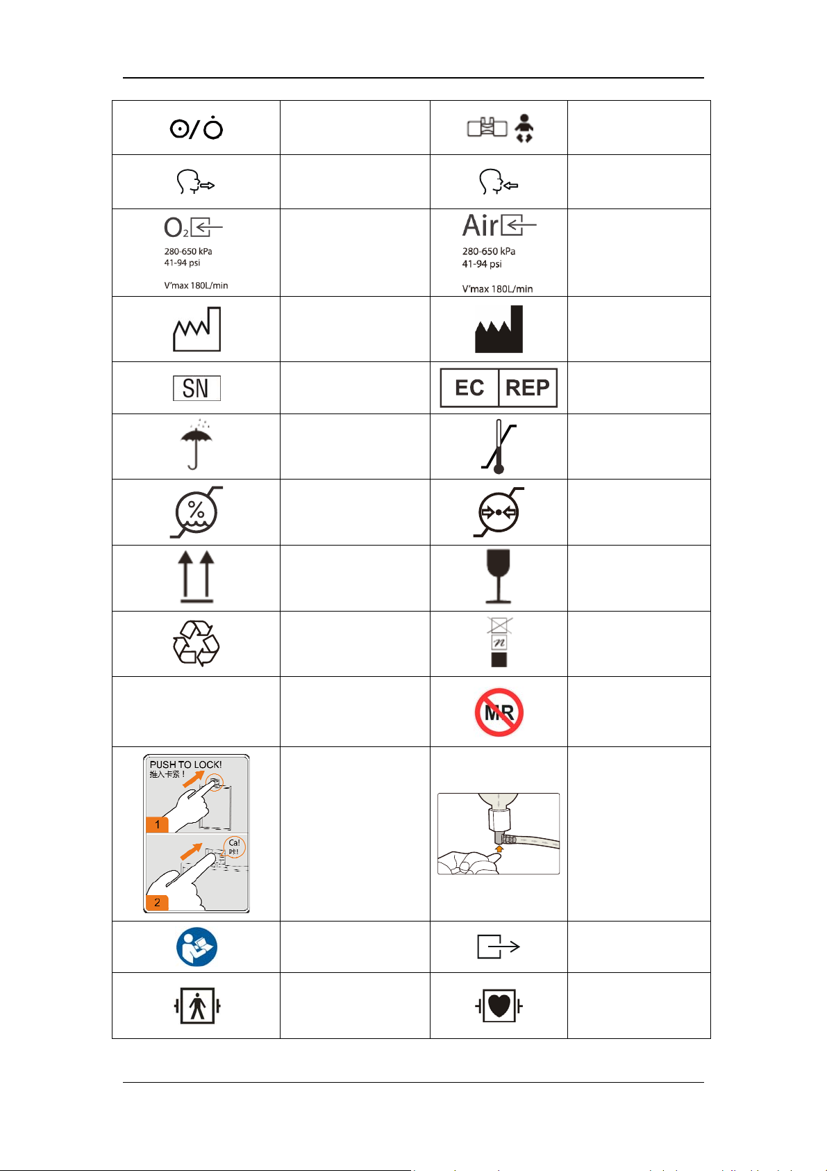
Power switch
Expiration connector
Oxygen supply
connector
Date of manufacture
Serial number
Keep dry
Humidity limitation
Neonatal flow sensor
connector
Inspiration connector
Air supply connector
Manufacturer
European community
representative
Temperature
limitation
Atmospheric pressure
limitation
IP21
This way up
Recyclable
Degree of protection
against harmful
ingress of water
Fragile, handle with
care
Stacking limit by
number
Not suitable for use
in an MRI
environment
High Efficiency
Particle Air (HEPA)
Water trap indicator
installation instruction
Refer to the operator's
manual
Defibrillation-proof
BF application part
Ventilator gas outlet
DEFIBRILLATION-
PROOF TYPE CF
APPLIED PART
1-10
Reset the paramagnetic oxygen sensor (NOTE: This operation can be
performed only by the Customer Service Department or authorized
personnel.)
The following definition of the WEEE label applies to EU member
states only.
This symbol indicates that this product should not be treated as
household waste. By ensuring that this product is disposed of
correctly, you will help prevent bringing potential negative
consequences to the environment and human health. For more detailed
information with regard to returning and recycling this product, please
consult the distributor from whom you purchased it.
* For system products, this label may be attached to the main unit
only.
The product bears CE mark indicating its conformity with the
provisions of the Council Directive 93/42/EEC concerning medical
devices and fulfills the essential requirements of Annex I of this
directive.
Unified circulation mark indicates that products marked them passed
all specified in the technical regulations of the Customs Union of the
procedure for the assessment (confirmation) of conformity and
complies with the requirements applicable to all the products technical
regulations of the Customs Union.
1-11

FOR YOUR NOTES
1-12

2 The Basics
2.1 System Description
2.1.1 Intended Use
This product is intended to be used in intensive care situations within a professional
healthcare facility, or during transport within a professional healthcare facility. This product
is intended to provide ventilation assistance and breathing support for adult, paediatric and
neonate patients. The product should be operated by properly-trained and authorized medical
personnel. This equipment is not suitable for use in an MRI environment.
2.1.2 Contraindications
There are no absolute contraindications for this product. For some special diseases, however,
some necessary treatments shall be taken for ventilator mechanical ventilation, or special
ventilation modes shall be adopted to prevent possible patient injury.
2.1.3 Components
The ventilator consists of a main unit (including pneumatic circuit, electronic system,
mechanical structure, display, CO
(model: C3), trolley, and support arm.
The ventilator is suitable for use within the PATIENT ENVIRONMENT. Connect the patient
to the ventilator via the patient breathing circuit. The applied part of the ventilator is
breathing masks.
module, SpO2 module), backup air supply, air compressor
2
2-1
2.2 Equipment Appearance
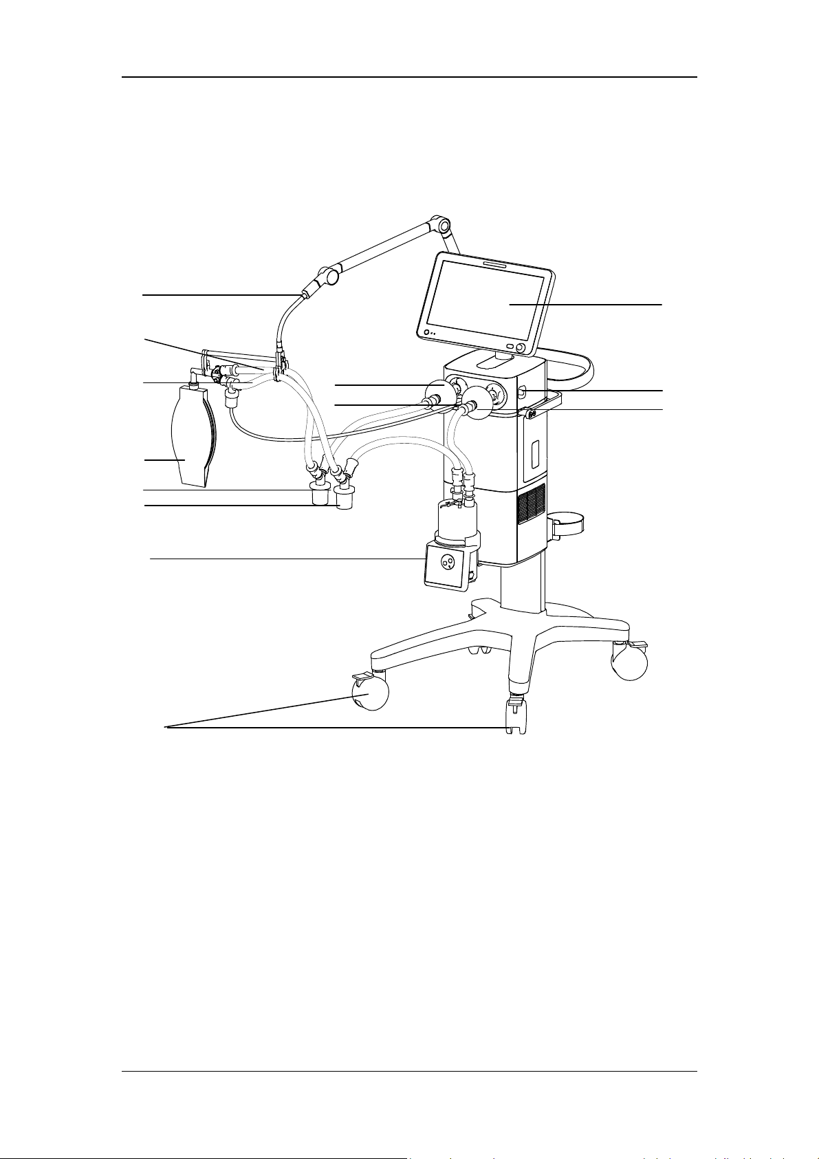
2.2.1 Front View
8
7
6
5
4
3
2
11
12
9
13
10
1
2-2

1. Caster and brake
The ventilator has four casters and all casters have brakes.
2. Humidifier
3. Inspiratory water trap
Collects condensed water in the inspiratory tube.
4 Expiratory water trap
Collects condensed water in the expiratory tube.
5. Test lung
6. Inspiratory tube
7. Expiratory tube
8 Support arm
Supports and hangs the patient tubing.
9. Display
10. Inspiratory filter
11. Expiratory filter
12 Nebulizer connector
To connect pneumatic nebulizer.
13. Leak test plug
For System Check or Flow Calibration.
2-3

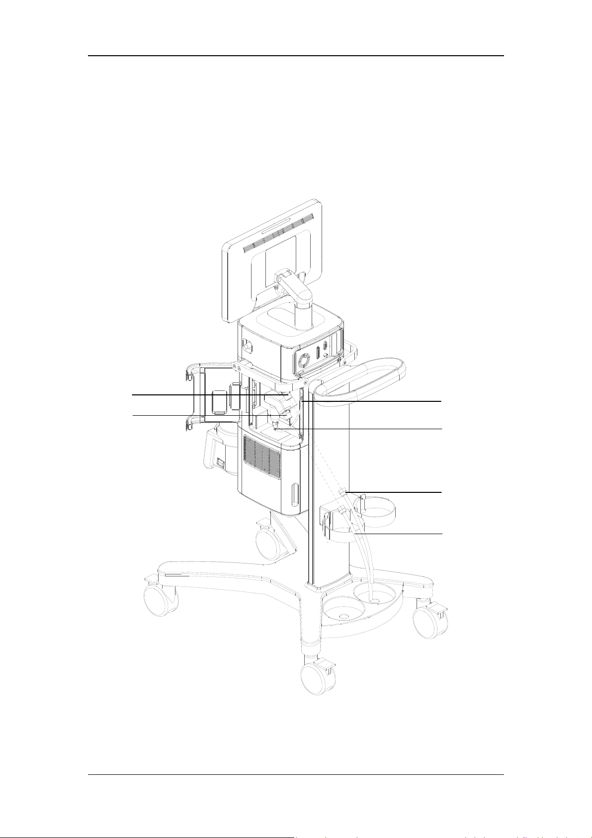
2.2.2 Rear View
5
4
3
2
1
6
7
8
9
10
1. Cylinder retaining clip
For retaining the gas cylinder.
2. Trolley rear handle
3. Nurse call connector
Connects to the hospital’s nurse call system and outputs nurse call signals when an
alarm occurs.
4. Main unit and display connector
5. RS-232 connector
Connects to the external calibration device for calibrating pressure. An external medical
device can be connected via this connector to communicate with the ventilator.
2-4

6. Display
A
B
C
A. USB connector
Conducts ventilator software upgrade, configuration information and history data (such
as patient data, alarm log) export, configuration transfer between machines of the same
type via USB device. The device can also be connected to the electronic nebulizer via
USB.
B. VGA connector
Outputs VGA video signals with the same contents to the primary display and connects
to the external display (supporting display with resolution of 1920*1080).
C. Network connector
A connector which supports connection with a PC to perform software upgrade and
connection with external medical and information device.
7. Neonatal flow sensor connector
Connects neonatal flow sensor.
8. Module slot
Inserts and identifies CO
9. AC power receptacle
10. Equipotential stud / lug
module and SpO2 module mentioned in this manual.
2
2-5

2.2.3 Air Compressor
The air compressor has two types of configurations: standby and non-standby.
In case of standby configuration, the compressor starts to deliver compressed air to the
ventilator or anesthesia machine automatically if the hospital central pipeline gas supply
stops supplying gas. The compressor stops delivering compressed air automatically when the
central pipeline gas supply returns to normal.
In case of non-standby configuration, central pipeline gas supply inlet is not available and
only compressed air outlet is available.
4
1
3
2
1. Power indicator
The power indicator is lit when the compressor is connected to power supply and the
power switch is turned on.
2. Status indicator (standby configuration)
The status indicator is lit when the central pipeline gas supply is applied.
3. Warning indicator
The warning indicator is lit when some failures occur to the compressor (e.g. internal
temperature abnormally high, semiconductor refrigeration failure, solenoid valve failure,
or fan failure). In this case, the compressor may shut off at any time and stop delivering
gas.
4. Pressure gauge
The pressure gauge indicates the air pressure at the compressed air outlet.
5. Air intake vent (with dust filter)
6. Power switch
5
6
7
8
Turn on or turn off the air compressor.
7. Mains power inlet (with fixing pressure plate)
2-6

8. Hourmeter
The hourmeter indicates the accumulated running time of the compressor (not including
the accumulated running time when the central pipeline gas supply is applied).
9. Compressed air outlet
10. Central pipeline gas supply inlet (standby configuration)
NOTE
Burn-in is required for the compressor before delivery. The reading indicated by
the compressor hourmeter shall be less than 150 hours at the time of delivery.
2-7

FOR YOUR NOTES
2-8
3 Installations and Connections
WARNING
Do not use antistatic or conductive masks or patient tubing. They can cause burns if
they are used near high frequency electrosurgery equipment.
To ensure optimum performance of the ventilator, re-do System Check each time
when accessories or components like patient tubing, humidifier, and filter are
replaced.
Adding accessories or other components to the breathing system of the ventilator
can increase system inspiratory and expiratory resistance.
3.1 Connect the Power Supply
A
B
C
A. AC power receptacle B. AC power cord C. Anti-unplugging hook of power
3-1
1. Turn the anti-unplugging hook of power to the right-hand side.
2. Insert the AC power cord into the AC power receptacle.
3. Put back anti-unplugging hook of power to clamp the power cord in place.
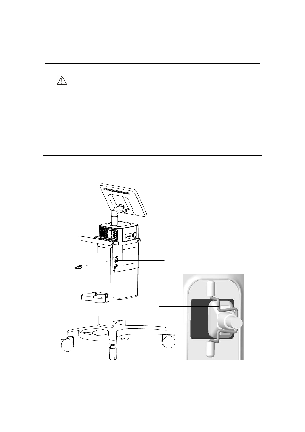
3.2 Connect the Pipeline Supply
A
B
C
D
E
F
A. Oxygen supply inlet B. Air supply inlet
C. Drainage tube and slot
D. Pushrod of water trap and drainage valve at air supply inlet
E. O
supply hose F. Air supply hose
2
3-2

This ventilator provides O
and air supply connectors. Supply hoses are marked in different
2
colors. The connector of each hose should not be exchanged with each other. Gas supply
hoses and the ventilator are connected as follows.
1. Check whether the sealing ring on the gas supply hose connection is in good condition
before connecting the gas supply hose. If the sealing ring is damaged, do not use the
hose. Replace the sealing ring to prevent leakage.
2. Align the hose connector with and insert it into the inlet of the O
supply or air supply
2
on the back of the ventilator.
3. Ensure that the gas supply hose is properly connected to the gas supply inlet. Tighten the
hose nut.
During use, the operator can check the water volume in the water trap through the transparent
observation window on the side door of the machine. If the water level is close to the filter
element, please take out the drain pipe from the slot and press the drainage valve pushrod of
water collection cup up to drain the water. Please place a container under the water trap to
catch the water, so that the water will not splash on the machine. Pushrod of drainage valve
will automatically re-place to its original position after drainage and then re-place the
drainage tube to the slot. Please contact your service personnel if any crack and leakage is
found on water trap.
NOTE
When draining the water, please use a container to catch the water, so that the
water will not splash on the machine.
If drainage in the ventilation status, please prevent water splash and use a container
to prevent water from directly spraying to the battery bottom.
WARNING
Inspect the oxygen supply connector carefully and ensure that there is no leakage.
If there is significant gas leakage, oxygen concentration in the surrounding
environment will exceed normal oxygen concentration in the atmosphere, resulting
in a potentially dangerous oxygen-enriched environment.
Place the supply hose carefully, avoiding exposure to the environment in which
possible damage to the supply hose is easily caused by cut or heating.
The compressed gas must be dry, and free from dust and oil. Gas pressure must be
280 kPa to 650 kPa. Otherwise, the correct functioning of the device is not assured.
3-3

3.3 Install the Gas Cylinder
CAUTION
Ensure that the gas cylinder is equipped with pressure-reducing valve.
A
B
C
A. Gas cylinder B. Cylinder fixing buckle C. Trolley base
1. Place the gas cylinder onto the trolley base.
2. Fix the gas cylinder via cylinder fixing buckle.
3-4

3.4 Install the Support Arm
F
G
E
D
C
B
A. Fixing block knob B. Fixing block C. Tube hook
D. Support arm joint E. Support bar F. Support arm joint
G. Support arm joint
A
3-5

1. Loosen the fixing block knob. Place the fixing block onto the handle at the rear of the
ventilator.
2. Tighten the fixing block knob.
WARNING
To prevent possible patient injury due to accidental extubation, check the support
arm joints and the connection security as necessary.
3. Adjust the support arm.
Support arm joint F or G: to adjust the upward-bending angle of the support arm, only
lift up the support bar to the desired position without the need to push the blue unlocking
key
bar, and then push and hold the blue key
hold the support bar and press it downward with the other hand. Release the blue
unlocking key
joint F or G can be adjusted for up to 130º.
Support arm joint D: swivel upward or downward to the desired position.
Hold the bottom of support arm or the support bar beside support arm joint G and swivel
it to the left, or to the right, with force to rotate the support arm to the desired position.
4. Place the patient tubing onto the tube hook.
. To adjust the downward-bending angle of the support arm, lift up the support
on support arm joint with one hand, and
after adjusting the support bar to the desired position. Support arm
3-6

NOTE
Operate support arm joint F or G with both hands as shown below. Operating with
a single hand will bring some risks.
The maximum weight of the support arm is 1 kg.
Please install the support arm according to the instruction on the handle of the
ventilator.
3.5 Install the Patient Tubing
WARNING
To minimize the risk of bacterial contamination or physical damage, remove and
install the bacterial filter with care.
To prevent patient or ventilator contamination, always use a bacteria filter between
the ventilator and the patient inspiratory limb.
CAUTION
The use of an expiratory filter may lead to a significant increase in expiratory
resistance. Excessive expiratory resistance may compromise ventilation and
increase patient’s work of breathing and intrinsic PEEP.
The patient tubing shall comply with the requirements of ISO 5367.
The bacteria filters shall comply with the requirements of ISO 23328-1 and ISO
23328-2.
The Heat & Moisture Exchange (HME) shall comply with the requirements of ISO
9360-1 and ISO 9360-2.
3-7

3.5.1 Install Adult/Pediatric Tubing
F
E
D
C
A. Inspiratory filter B. Expiratory filter
C. Inspiratory water trap D. Expiratory water trap
E. HME F. Support arm hook
B
A
1. Mount the filters onto the inspiratory and expiratory ports.
2. Connect the inspiratory filter to the water trap via the tubing. Then connect the water
trap to the Y piece via the tubing.
3. Connect the expiratory filter to the water trap via the tubing. Then connect the water trap
to the Y piece via the tubing.
4. Connect the patient side of the Y piece to the HME and then connect the HME to the
patient.
5. Place the patient tubing onto the support arm hook.
3-8

3.5.2 Install Neonate Tubing
The use of a F&P850 humidifier is recommended when installing neonate tubing.
B
D
A
C
A. Neonatal flow sensor tubing connector B. Inspiratory filter
C. Expiratory filter D. Support arm hook
E. Neonatal flow sensor F. Neonatal test lung
G. Neonatal flow sensor tubing H. Inspiratory water trap
I. Expiratory water trap
E
F
G
H
I
3-9

1. Mount the filters onto the inspiratory and expiratory ports.
2. Connect the inspiratory filter to the humidifier inlet via the tube.
3. Connect the humidifier outlet to the water trap via the tubing. Then connect the water
trap to the Y piece via the tubing.
4. Connect the expiratory filter to the water trap via the tubing. Then connect the water trap
to the Y piece via the tubing.
4. Connect the neonatal flow sensor tubing to the neonatal flow sensor tubing connector on
the ventilator.
5. Connect the small end of the neonatal flow sensor to the Y piece, and the large end to
the neonatal test lung. As shown in the figure below:
WARNING
Please keep the sensor tubing upright during installation and use of the neonatal
flow sensor.
6. Place the patient tubing onto the support arm hook.
3-10

3.6 Install the Humidifier
WARNING
To prevent possible patient injury and equipment damage, do not turn on the
humidifier until the gas flow has started and is regulated.
To prevent possible patient injury and equipment damage, ensure the humidifier is
set to appropriate temperature and humidity.
NOTE
The humidifier shall comply with the requirements of ISO 8185. The humidifier
assembly and its installation steps described in this section are only for reference.
3.6.1 Install the Humidifier onto the Ventilator
F
D
A
E
C
B
A. Humidifier B. Humidifier mounting plate C. Humidifier bracket slot
D. Screw E. Humidifier inlet F. Humidifier outlet
3-11

1. Align the humidifier mounting plate and the slot, and slide the humidifier in.
2. Tighten the screw.
3. Mount the filters onto the inspiratory and expiratory ports.
4. Connect the inspiratory filter to the humidifier inlet via the tube.
5. Connect the humidifier outlet to the water trap via the tubing. Then connect the water
trap to the Y piece via the tubing.
6. Connect the expiratory filter to the water trap via the tubing. Then connect the water trap
to the Y piece via the tubing.
7. Place the patient tubing onto the support arm hook.
The range of the ventilator breathing system (VBS):
Inspiratory and expiratory gas pathway resistance: 0 to 6 cmH
VBS compliance: 0 to 5 ml/cmH
2
O.
O/ (L/s) at 60 L/min
2
3-12
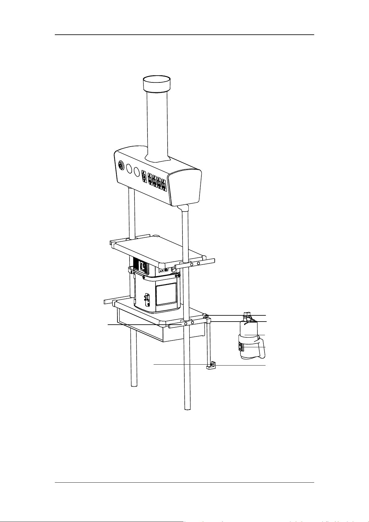
3.6.2 Install the Humidifier onto the Pendant
A
G
F
A. Humidifier B. Fixing block knob C. Fixing block
D. Humidifier mounting plate E. Humidifier bracket slot F. Screw
G. Beam
3-13
B
C
D
E

1. Loosen the fixing block knob. Place the fixing block onto the pendant beam.
2. Tighten the fixing block knob.
3. Align the humidifier mounting plate and the slot, and slide the humidifier in.
4. Tighten the screw.
5. Install the patient tubing. For detailed connection method, refer to 3.6.1 steps 3 through
7.
WARNING
Before installing the humidifier, ensure that the humidifier connector shall be lower
than the ventilator’s breathing connectors and the patient.
3.7 Install the Nebulizer
NOTE
Install the specified nebulizer. The nebulizer assembly and its installation steps
described in this section are only for reference. Refer to the nebulizer
accompanying directions for use to install and use the nebulizer.
To prevent the expiration valve from sticking due to nebulized medications, use
only medications approved for nebulization, and regularly check and clean or
replace the expiration valve membrane.
Do not use an expiratory filter or HME in the patient’s breathing circuit during
nebulization. Nebulization can cause an expiratory side filter to clog, substantially
increasing flow resistance and impairing ventilation.
Connect the nebulizer to the inspiratory limb. Connecting the nebulizer between
the patient connector and the endotracheal tube increases dead space ventilation.
3-14
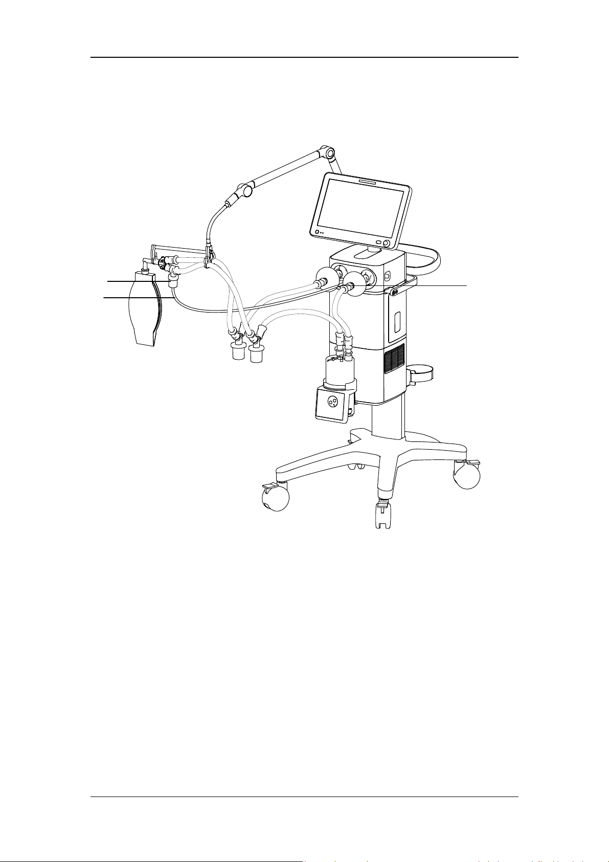
3.7.1 Install Pneumatic Nebulizer
C
B
A. Nebulizer connector B. Nebulizer tube C. Nebulizer
A
1. Connect one end of the nebulizer tube to the nebulizer connector and the other end to the
nebulizer.
2. Install the nebulizer in the inspiratory limb via the tube.
3-15

3.7.2 Install Electronic Nebulizer
C
A
B
A. Nebulizer B. USB controller C. USB connector
1. Insert the USB connector of USB controller into the USB port below the display.
2. Connect the nebulizer with the patient tube. Refer to the nebulizer accompanying
operator’s manual for the details.
WARNING
Always maintain the nebulizer in a vertical orientation while in the patient circuit.
This orientation helps prevent patient secretions and condensate from
contaminating the aerosol generator of the nebulizer and ensures proper
nebulization.
Refer to the nebulizer accompanying operator’s manual to install and use the
nebulizer.
3-16
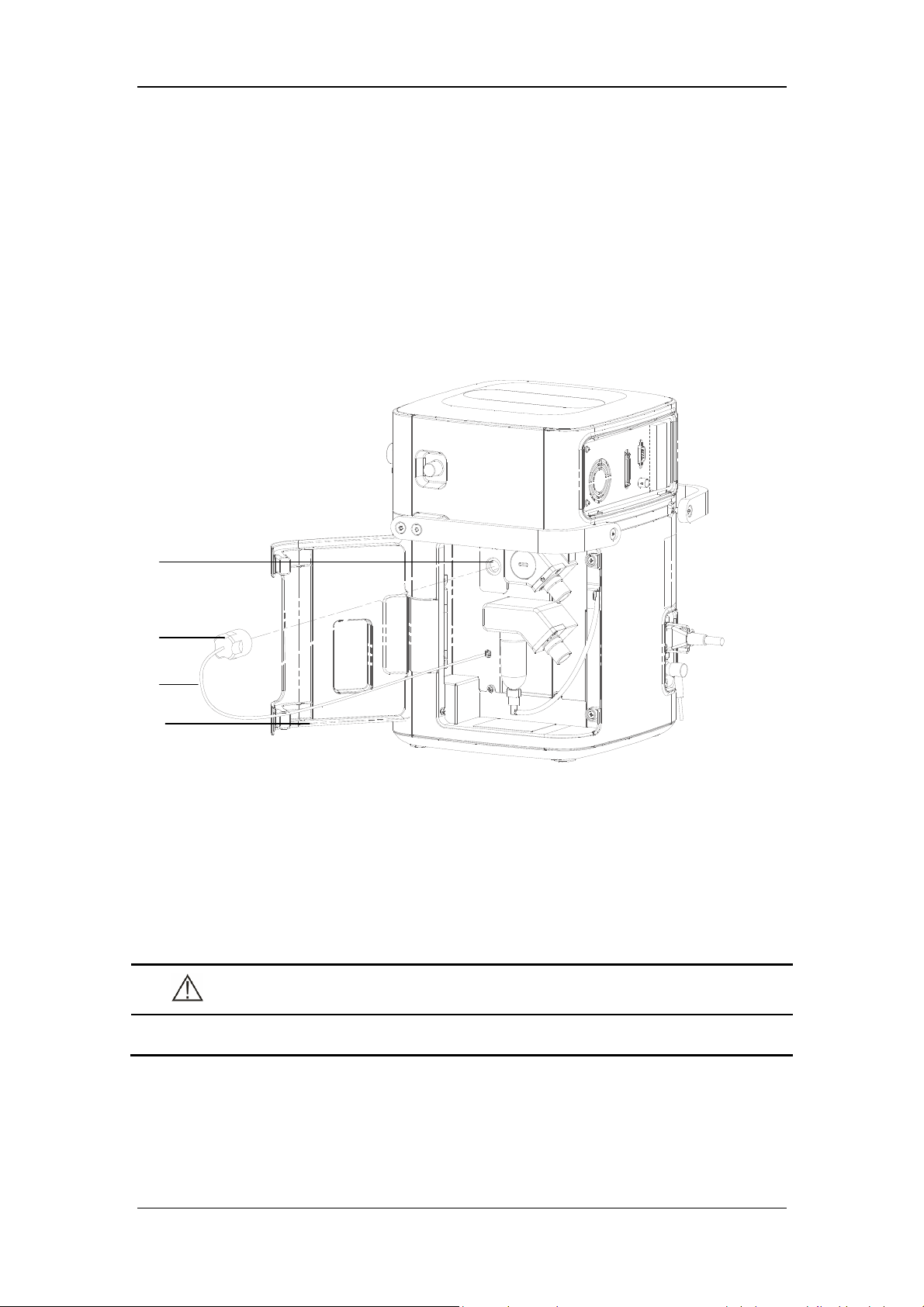
3.8 Install the Oxygen Sensor
This ventilator could be equipped with O2 Cell or Paramagnetic O2 Sensor. O2 Cell is a
consumable product and the service life is around 1 year and thus needs to be replaced
periodically. O
Schedule for calibration cycle. The Paramagnetic O
and no replacement is needed.
3.8.1 O2 Cell
Cell need to be calibrated regularly. Please refer to 13.2 Maintenance
2
Sensor could be used for a long term
2
A
B
C
D
A. Fixing seat B. O
C. O
Cell connector cable D. Main unit maintenance door
2
1. Rotate the O
2. Connect the O
Cell clockwise to install it.
2
Cell connection cable.
2
3. Close the main unit maintenance door.
CAUTION
Cell
2
To reduce the risk of explosion, do not burn the O
3-17
cell or force the cell open.
2

NOTE
If ICU work normally, the service life of O
Cell is one year. The service life of O2
2
Cell is an approximate specification only. The actual cell life depends on operating
environment. Operation at higher temperatures or higher O
% shortens the life.
2
3.8.2 Paramagnetic O2 Sensor
If the paramagnetic O2 sensor configuration is selected, its installation has been completed
before the ventilator was dispatched from the factory.
WARNING
Under the normal usage, the ventilator equipped with paramagnetic O
meets the requirements of ISO 80601-2-12 on shock and vibration test conditions
for mobile ventilators and also complies with ISO80601-2-55 requirements of shock
and vibration test conditions for special-purpose gas monitors during unexpected
transfer. Shock and vibration beyond the standard will damage Paramagnetic O
Sensor and please place the ventilator into the package provided by the
manufacturer when transferring the ventilator.
sensor
2
2
3-18

3.9 Install Module
C
B
A
A. Latch at the bottom of the module B. Module C. Module slot
This equipment supports hot replacement of all modules. That is, you can plug in or unplug a
module without needing to shut down the machine.
Plug in module: align the module to the corresponding slot and push it in until the latch
at the bottom of the module clicks into place. After plugging in the module, please
confirm whether the indicator light on the module is on or off. If it is not switched on,
please re-insert the module.
Unplug module: pull the module outwards after lifting the latch upwards, and remove
the module.
3-19

FOR YOUR NOTES
3-20

4 User Interface
4.1 Display Controls
2
1
7 3 6 5
The control unit is characterized by a small number of operating elements. Its main elements
are:
1. Display (touch screen)
The display shows the software screen of the ventilator system. You can select and
change settings by touching the screen.
2. Alarm indicator light
The alarm indicator light indicates the priority of an active alarm by flashing different
colors at different frequencies.
3. Control knob
Press the control knob to select menu items or confirm settings. Rotate clockwise or
counterclockwise to scroll through menu items or change settings.
4. Alarm AUDIO PAUSED key
Press to initiate the AUDIO PAUSED for 120 seconds, so that audible alarm tones of
the active alarms are switched off. If AUDIO PAUSED exceeds 120 seconds, the
AUDIO PAUSED status terminates automatically and audible alarm tones are restored.
4
4-1

If a new alarm is triggered under AUDIO PAUSED status, the AUDIO PAUSED status
terminates automatically and audible alarm tones are restored. Under AUDIO PAUSED
status, press this key a second time to terminate AUDIO PAUSED status.
5. Battery indicator light
Lit: indicates that the battery is being charged or is already fully charged, and the
ventilator is operating on external power supply.
Flash: when the ventilator is operating on battery power.
Not lit: indicates that the ventilator is not connected to an external power supply, or that
the ventilator does not have a battery installed, or that there is a fault with the battery.
6. External power indicator light
Lit: when the ventilator is connected to an external power supply.
Not lit: when the ventilator is not connected to an external power supply.
7. Power switch (with indicator light)
Press to power on/off the system. Switch is lit when the system powers on the ventilator
and not lit when the system powers off the ventilator.
18
The ventilator display shows ventilation parameters, pressure/flow/volume waveforms and
spirometry loops, etc.
The following is an example of Waveforms screen. Display screen may vary subject to the
configurations.
1
2
3
4
5
6
7
9
8
10
11
12
13
14
15
17
16
19
4-2

1. Ventilation mode field
Displays Standby or active ventilation mode and ventilation assist indication.
2. Ventilation type field
Displays Non-invasive or Invasive ventilation type:
Displays the icon for Non-invasive mask and NIV word when the ventilation
type is Non-invasive.
Displays the tube icon when the ventilation type is invasive and the ATRC
function is switched off.
Displays the tube icon and tube diameter when the ventilation type is
invasive and the ATRC function is switched on.
3. Patient type / Inspiratory trigger icon field
Indicates current patient type. The icon for Inspiratory trigger is
, which is displayed
for 1 s.
4. Alarm message field
Displays the active alarm messages. When there are multiple alarm messages, the
number of alarms is displayed. In this case, by clicking the alarm message field, you can
view current alarm messages, alarm subordination (alarm chain), alarm occurrence time
and alarm level, as well as suggested measures after the occurrence of an alarm, or alarm
help information in the opened interface.
5. Prompt message field
Displays the active prompt messages.
6. Inactivated alarm indicating field
When the icon
is displayed, it indicates that there are most recent alarms but the
alarm conditions have disappeared. By clicking this icon, you can view recent alarms
(up to 9 alarm messages are displayed) in the opened interface. You can also clear recent
alarms by pressing the [Reset] key.
7. Alarm AUDIO PAUSED field
When the icon for 120-second alarm AUDIO PAUSED countdown, which is
displayed, it indicates that the audible alarm tones are paused.
4-3
, is

8. Gas supply icon field
By selecting this icon, you can check gas supply pressure, spare air source status and
other information on the opened interface.
9. USB icon field
The icon is highlighted when the system is connected to an identifiable USB device. By
selecting this icon you can export screen, data and transfer settings in the opened
interface.
10. History icon field
By selecting this icon, you can check historical data on the opened interface, including
graphic trends, tabular trends, setting trends and event logbook.
11. Freeze icon field
Select this icon to enter freeze status. In this status, the system temporarily pauses the
real-time refreshing of waveforms and loop graphs on the screen, so that you can review
specific patient data.
12. System time field
Displays current system time. By selecting this field, you can set the system time in the
opened menu.
13. Screen capture icon field
By select this icon, you can capture and save the screen.
14. Power status icon field
Displays the status of currently-used power supply.
15. Soft key field
Displays soft keys: Alarm Display, O
↑/ Suction, Nebulizer, Tools, Lock, Menu,
2
Standby and so on.
16. Parameter setup quick key field
Displays ventilation setting parameters corresponding to the active ventilation mode.
17. Ventilation mode setup field
Displays the keys for setting up ventilation modes.
18. Waveforms/Spirometry/Values/Big Numeric Screen
Displays Waveforms, Spirometry, Values or Big Numeric Screen
19. Trigger spontaneous breathing icon
Displays the icon when the patient has spontaneous breathing.
4-4

4.2 Waveforms Screen
Select the [Waveforms] key to access the interface as shown below.
Select
1. Graphic trend 2. Dynamic lung zone
key and open the screen of graphic trend and dynamic lung as follows.
1
2
4-5

4.2.1 Graphic trend
Graphic trend records the trend of parameter values. It is reflected through a curve. Every
point on the curve corresponds to the value of monitored parameter at a specific time point.
Up to 30 minutes monitored parameter graphic trend could be displayed.
Select graphic trend parameter name area and set the monitored parameter graphic trend to be
displayed in the pop-up interface. Adjust the cursor by selecting the graphic trend or twist the
control knob after selecting the graphic trend.
4.2.2 PulmoSight
4.2.2.1 PulmoSight status
The brightness and darkness of lung diagram represents the inspiratory and expiratory
process. When inspiration, the lung is bright. When expiration, the lung is dark.
PulmoSight status Description PulmoSight status Description
Compliance is
normal.
Compliance is
large. The alveoli
contour is
thinned.
Volume is large.
Resistance is large.
The airway edge
thickened.
Compliance is small.
The alveoli contour
is thickened.
Volume is low.
4-6

4.2.2.2 Set PulmoSight
Select key, set [Ref. Compliance] and [Ref. Resistance] in the menu. There are three
ways of setting parameters:
Select setting parameter areas and direct edit.
Select [Restore Defaults] key, and the system will automatically load the defaults
corresponding to current patient type.
Select [Use Current] key, and use the compliance monitored value and resistance
monitored value displayed on the screen.
4.3 Spirometry Screen
Select the [Spirometry] key to access the screen as shown below.
4-7

The interface as shown below is displayed by pressing the key
.
Spirometry loops reflect patient lungs function and ventilation condition as well, such as the
patient’s lungs compliance, over-inflation, breathing system leakage and airway blockage.
The system provides lung function loops, including [Paw-Volume] loop, [Flow-Volume]
loop and [Flow-Paw] loop, the data for which is collected from the waveform data on
pressure, flow and volume. When a mainstream CO
module is configured, a [V-C O2 ] curve
2
can be displayed.
Up to two types of spirometry loop are displayed at a time. To select the desired loop:
1. Select [Spirometry] on the main screen.
2. Set the desired loop or V-CO
loop to be displayed.
2
The ventilator provides the function of reference loop. When [Save Ref.] is selected, the
current respiratory cycle loop is saved as a reference loop, and the time it was saved is
displayed. By selecting [Display Ref.] and then selecting a time point, the reference loop
saved at that time can be viewed. By selecting [Display Ref.] and then selecting [OFF], the
reference loop being displayed can be hidden.
The ventilator saves up to 5 reference loops. If 5 reference loops have already been saved, the
system will automatically clear the oldest reference loop and save the loop of the current
respiratory cycle as reference loop if [Save Ref.] is selected again.
4-8
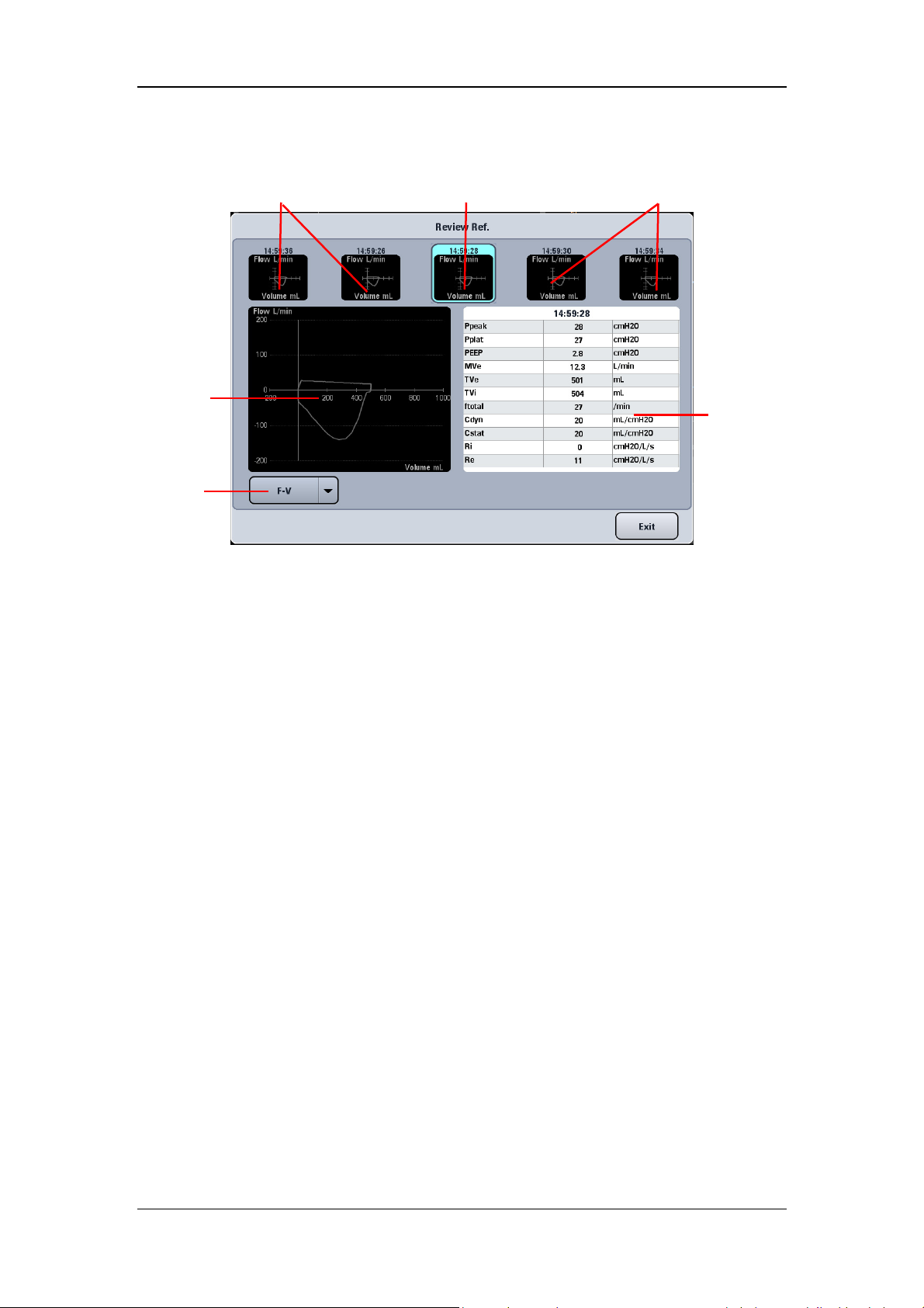
Select the [Review Ref.] key to display the review reference loop menu.
Non-selected reference loop
Selected
reference loop
(large)
Loop type
Selected reference loop (small)
Non-selected reference loop
Parameter
data area
Small loop windows : These small graphic windows show the reference loops. The
reference loops (up to 5) are displayed from oldest (left) to newest (right). The
information of selected reference loop is displayed in cyan highlight.
Large loop window : This graphic window shows an enlarged view of the selected
reference loop.
Loop type : By selecting loop type, you can choose the type of loop to review.
Parameter data area : This area displays monitored parameter data related to the saved
reference loops.
4-9

4.4 Measured Values Screen
Select the [Values] key on the screen to open the interface as shown below.
4.5 Big Numeric Interface
Select the [Big Numeric] key on the screen to open the interface as shown below.
4-10

4.6 History
Select the key on the screen to access the interface as shown below. You can view
tabular trend, graphic trend, setting trends, and event logbook in the History window.
4.6.1 Graphic Trend
Graphic trend records the trend of parameter values. It is reflected through a curve. Every
point on the curve corresponds to the value of physiological parameter at a specific time point.
Graphic trend also records parameter alarm events. Graphic trend data displays at one-minute
intervals by default unless the zoom is selected.
Current cursor. The
corresponding time
displays above the
cursor. If alarms
occurred at that time,
the corresponding
alarm information
will also be
displayed above the
cursor.
Event marker. The dotted, colored line indicates a parameter alarm event occurred
at that time. A parameter alarm event is indicated by a dotted line in the same
color with alarm. If multiple events occurred, the dotted line is in the same color
of the highest level alarm.
The parameter
data of the time
indicated by
cursor.
4-11

4.6.1.1 About Graphic Trend
Graphic Trend displays the time and date on the horizontal axis.
Graphic Trend displays the parameter data on the vertical axis.
Graphic Trend displays the most recent trend data on the rightmost side.
Graphic Trend is not stored when the machine is in standby status.
The system can display a rolling 96 hours of continuous trend data.
Graphic Trend highlights the parameter data in the corresponding alarm color if an
alarm condition existed for the parameter at the time of trend record storage.
Select [Previous Event] to move the cursor to the previous event from its current
position.
Select [Next Event] to move the cursor to the next event from its current position.
4.6.1.2 Zoom
In the Graphic Trend interface, you can set [Zoom] to [5 min], [10 min], [15 min], [30 min],
[1 h] and [2 h].
4.6.1.3 Display Group
In the Graphic Trend window, you can set [Display Group] to [Pressure], [Volume], [Time],
[Gas], [SpO
], [Other] and [All].
2
4-12
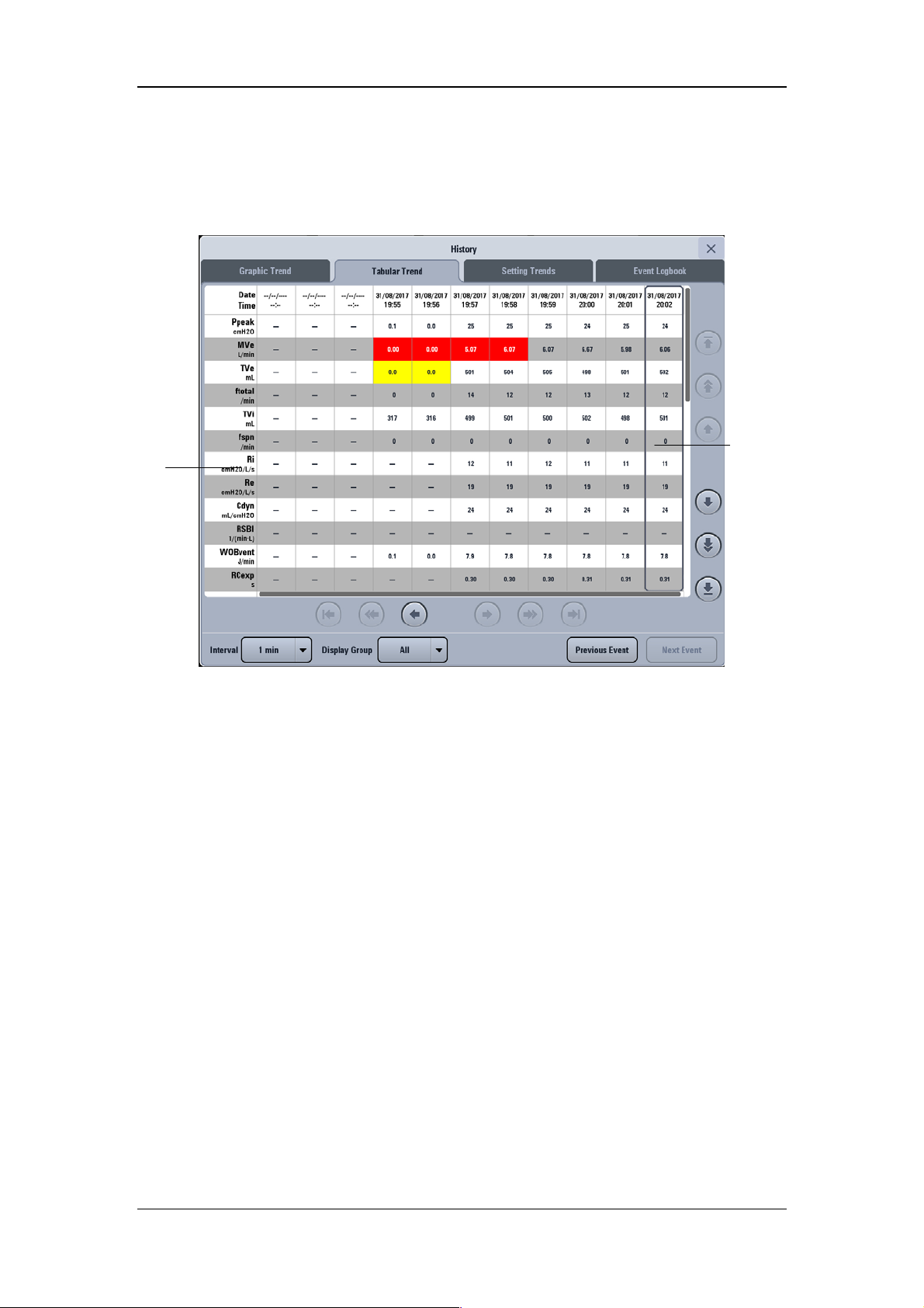
4.6.2 Tabular Trend
Parameter
You can view the patient’s monitored parameter data and events under the Tabular Trend tab.
Trend data displays at one-minute intervals by default.
Cursor
4.6.2.1 About Tabular Trend
Tabular Trend displays the time and date on the horizontal axis.
Tabular Trend displays the parameter data on the vertical axis.
Tabular Trend displays the most recent trend data on the rightmost side.
Tabular Trend is not stored when the machine is in standby status.
The system can display a rolling 96 hours of continuous trend data.
Tabular Trend highlights the parameter data in the corresponding alarm color if an alarm
condition existed for the parameter at the time of trend record storage.
Select [Previous Event] to move the cursor to the previous event from its current
position.
Select [Next Event] to move the cursor to the next event from its current position.
4.6.2.2 Interval
In the Tabular Trend window, you can set [Interval] to [1 min], [5 min], [10 min],
[15 min], [30 min], [1 h], and [2 h].
4-13

p
4.6.2.3 Display Group
In the Tabular Trend window, you can set [Display Group] to [Pressure], [Vol ume], [Time],
[Gas], [SpO
], [Other] and [All].
2
4.6.3 Setting Trends
Setting Trends is used to record ventilation mode settings and parameter settings.
Ventilation
mode and
setting
arameter
4.6.3.1 About Setting Trends
Cursor
Settings Trends displays the time and date on the horizontal axis.
Settings Trends displays the ventilation mode and setting parameter on the vertical axis.
Settings Trends displays the most recent trend data on the rightmost side.
4-14

4.6.4 Event Logbook
Event Logbook records such events as power-on/off, ventilation mode setup, ventilation
parameter setup, technical alarm, physiological alarm, standby status, starting ventilation,
new patient, last patient, special function, default settings management, calibration, system
check, circuit test, PulmoSight set, and alarm AUDIO PAUSED and O
Cursor
therapy event.
2
Detailed
information of
the event
indicated by
the cursor
4.6.4.1 About Event Logbook
Event Logbook displays the most recent record at the top.
The system can store up to 5000 records of Event Logbook.
NOTE
The system can store up to 5000 records of Event Logbook. When a new event
occurs after 5000 events are already stored, the new event overwrites the earliest
one.
4.6.4.2 Filter
In the Event Logbook window, you can set [Filter] to [High Alarms], [Med Alarms], [Low
Alarms], [All Alarms], [Operation Information], and [All Events].
4-15

4.7 Freeze
The freeze function’s feature is that it can pause the real-time refreshing of waveforms and
spirometry loops on the screen, so that you can have a close examination of the patient’s
status within this time period. The reviewed data are waveforms and spirometry loops in the
60 seconds before entering freeze state.
4.7.1 Enter Freeze Status
When in non-standby status and non-freeze status, press the [Freeze] key will display the
[Freeze active. Press the Freeze Key to Unfreeze] prompt message on the screen and the
system will enter freeze status. Freeze cursors will appear on the screen near the waveforms
and loops. All displayed waves and loops are frozen, namely, they are not refreshed. The data
in the parameter area are refreshed normally. In freeze status, the [Save Ref. Loop] key is
disabled, and you cannot save a loop as a reference loop. However, you can view reference
loops that are already saved.
4.7.2 View Frozen Waveforms
In freeze status, cursors appear on the waveforms. You can rotate the control knob clockwise
or counterclockwise to move the cursor to view the waveforms.
Cursor
4-16
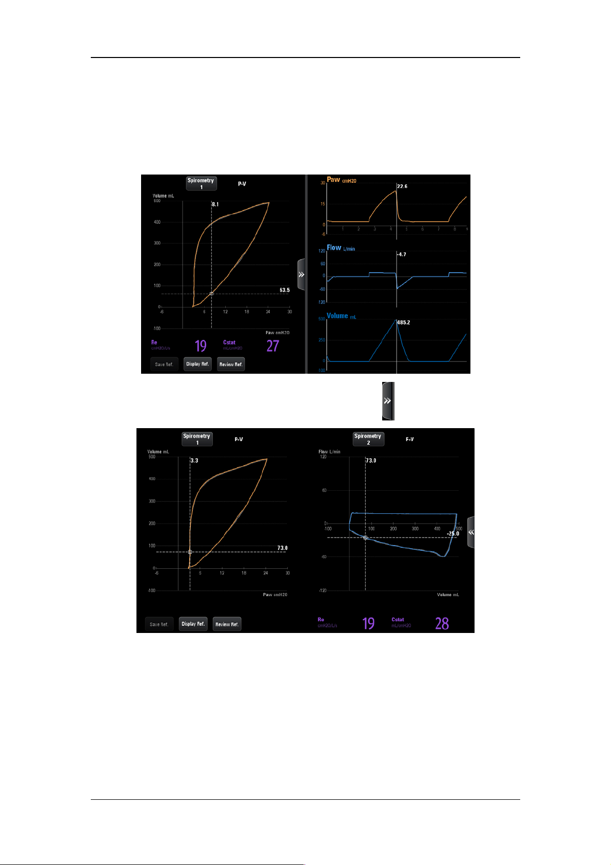
4.7.3 View Frozen Loop
In freeze status, cursors appear on the loops. You can rotate the control knob clockwise or
counterclockwise to move the cursor to view the loops.
The interface as shown below is displayed by pressing the key
.
4.7.4 Exit Freeze Status
When in freeze status, press the [Freeze] key again to exit the freeze status. In freeze status,
if no operation is performed on the ventilator for more than three (3) minutes, the system
exits freeze status automatically.
4-17

4.8 Screen Capture
By pressing this key on the main screen , the system will capture and save the screen
automatically. The screen capture is saved in “bmp” format. The system can store up to 20
screen captures.
4.9 Lock Screen
Press the [Lock] key on the main screen to enter locked status, and the prompt message
[Screen locked. Press the Lock button to unlock screen.] will be displayed. During the
period of screen locked, only
screen, control knob, and other keys are disabled. Press this key a second time to unlock the
screen.
, [O2↑ Suction], and [Lock] keys are enabled. Touch
4-18

5 System Settings
5.1 Date & Time Settings
1. Select the system time field on the main screen to pop up time setup menu.
2. Set [Date] and [Time].
3. Set [Date Format] to [YYYY-MM-DD], [MM-DD-YYYY] or [DD-MM-YYYY].
4. Set [Time Format]: [24 h] or [12 h].
5.2 Export to USB
The ventilator’s exportation function provides the ability to export some data or settings to
USB device.
5.2.1 Export Screen
Screen exportation involves exporting a saved screen capture for the ventilator. The exported
file is saved in “bmp” format. This ventilator could save up to 20 screen captures.
To export screen capture,
1. Insert the USB device into the USB connector of the ventilator. The
highlighted on the main screen.
2. By selecting the
3. On the opened interface, select the [Export Screenshot] tab first and then click the
[Export Screenshot] key. The system will run a check to verify that there is enough
storage space available on the USB device. If there is sufficient space, the system will
start to export the screen.
4. After exporting is completed, select [Remove USB Device] to remove the USB device.
key, the system will open the USB settings interface.
key is
5.2.2 Export Data
Exporting data means to export data from the ventilator, such as patient demographics,
current setting parameters, current alarm limits, trend data and so on.
To export data,
1. Insert the USB device into the USB connector of the ventilator. The
highlighted on the main screen.
2. By selecting the
key, the system will open the USB settings interface.
5-1
key is

3. On the opened interface, select the [Export Data] tab and then select the [User Export]
key. The system will run a check to verify that there is enough storage space available
on the USB device. If there is sufficient space, the system will export data including
patient information, current parameter settings, current alarm limits, tabular trend,
PEEPi measured value, P0.1 measured value, Vtrap measured value, and NIF measured
value, etc. The format of the exported data is “html”.
4. If you need to export calibration data, event logbook and self-check logbook in addition
to the above data, select the
run a check to verify that there is sufficient storage space available on the USD device.
If there is sufficient space, the system will start to export data. The exported data is
encrypted in the format of “blg”.
5. After exporting is completed, select [Remove USB Device] to remove the USB device.
[Factory Export] tab and enter password. The system will
NOTE
If you need to check the exported data in format of “blg”, please contact the
Customer Service Department.
5.2.3 Transfer Settings
You can export or import settings, while unit is in standby.
To export settings,
1. Make sure that the machine is in Standby status.
2. Insert the USB device into the USB connector of the ventilator. The key is highlighted
on the main screen
3. By selecting the
4. Select [Transfer Settings] → Enter system password → [Export Settings] in the
opened interface. The system will run a check to verify that there is sufficient storage
space available on the USB device. If there is sufficient space, the system will save the
current settings and machine defaults to the USB device.
.
key, the system will open the USB settings interface.
5. After exporting is completed, select [Remove USB Device] to remove the USB device.
5-2

To import settings,
1. Make sure that the machine is in Standby status.
2. Insert the USB device into the USB connector of the ventilator. The key is highlighted
on the main screen
3. By selecting the
4. Select [Transfer Settings] → Enter system password → [Import Settings] in the
opened interface. The system will upload the Ventilator settings saved in the USB
device.
5. After exporting is completed, select [Remove USB Device] to remove the USB device.
.
key, the system will open the USB settings interface.
5.3 Basic Settings
5.3.1 Set Flow/Tpause(%)
1. Select [Menu]→[Setup]→[Ventilation].
2. Set [Flow/Tpause(%)] and toggle between [Flow] and [Tpause(%)]. Use
corresponding ventilation settings in the V-A/C, V-SIMV or CPRV ventilation mode,
according to [Flow/Tpause(%)].
5.3.2 Set Tinsp/I:E
1. Select [Menu]→[Setup]→[Ventilation].
2. Set [Tinsp/I:E] and toggle between [Tinsp] and [I:E]. Based on [Tinsp/I:E], adopt the
corresponding Tinsp or I:E ventilation parameter settings for the V-A/C, P-A/C, PRVC,
CPRV and DuoLevel (when the time parameter for DuoLevel is [f] ) ventilation modes.
5.3.3 Set IBW/Height
1. Select [Menu]→[Setup]→[Ventilation].
2. Set [IBW/Height] and toggle between [IBW] and [Height]. When the ventilator is in
the standby mode, set the ideal body weight or height. The system calculates default
values of TV, f, and fapnea in the ventilation mode automatically based on the set IBW
or height and gender.
5-3

5.3.4 Set TV/IBW
1. Select [Menu]→[Setup]→[Ventilation].
2. Set [TV/IBW]: set to an appropriate ratio. The system will calculate the default tidal
volume (TV) in the ventilation mode depending on [TV/IBW].
5.3.5 Setup DuoLevel
1. Select [Menu]→[Setup]→[Ventilation].
2. Set [DuoLevel Setup]: [Thigh] or [f].
In case of DuoLevel ventilation mode, the settable time control parameters are
[Thigh] and [Tlow] if [DuoLevel Setup] is set to [Thigh].
In case of DuoLevel ventilation mode, the settable time control parameters are [f]
and [Tinsp] if [DuoLevel Timing] is set to [f] and [Tinsp/I:E] is set to [Tinsp].
In case of DuoLevel ventilation mode, the settable time control parameters are [f]
and [I:E] if [DuoLevel Timing] is set to [f] and [Tinsp/I:E] is set to [I:E].
5.3.6 Set Invasive Apnea Mode
1. Select [Menu]→[Setup]→[Ventilation].
2. Set [Invasive Apnea Mode]: [Volume Control] or [Pressure Control]. In case of
invasive ventilation in V-SIMV, P-SIMV, PRVC-SIMV, CPAP/PSV, PSV, VS,
Duolevel and APRV mode, the settable apnea ventilation control parameter is
[TVapnea] if [Invasive Apnea Mode] is set to [Volume Control], and is [ΔPapnea] if
[Invasive Apnea Mode] is set to [Pressure Control].
5.3.7 Set O2% increment during O2↑ period
1. Select [Menu]→[Setup]→[Ventilation].
2. Set [Increase O
patient types. After initiation of oxygen enrichment, the system will compare “current
oxygen concentration + oxygen enrichment” with “100vol.%” and start ventilation
according to the lower of the two values.
% during O2↑]: set oxygen enrichment in accordance with different
2
5-4

5.3.8 Set Oxygen Sensor Monitoring
1. Select [Menu]→[Setup]→[O2 Sensor].
2. Set the [Monitoring]:
concentration of patient’s inhaled gas can be monitored. You can switched off if oxygen
concentration monitoring function accompanying the ventilator is not needed. In this
case, the [O
Oxygen Sensor Monitoring off, the ventilator will disable relevant alarm messages and
prompt messages.
Monitoring Off] prompt message is displayed on the screen. After
2
(ON) or (OFF). When the switch is ON, oxygen
CAUTION
Switching off oxygen concentration monitoring is allowable. To prevent potential
patient injury, it is suggested not to switch off oxygen concentration monitoring
continuously.
NOTE
The system total response time for oxygen concentration monitoring is 23s.
It takes approximately 3 minutes from powering on the ventilator to reaching the
oxygen concentration monitoring performance specified in section B.7 of this
manual.
5-5

5.4 Screen Settings
5.4.1 Adjust Screen Brightness
1. Select [Menu] → [Screen] → [Brightness/Volume].
2. Select
3. If the above screen brightness is not satisfactory, set [Brightness] directly: 1 to 10. T1 is
the darkest setting and 10 is the brightest. If the ventilator is battery powered, you can
select a less bright screen to save battery capacity.
or and switch to corresponding screen brightness default.
5.4.2 Adjust Key Volume
1. Select [Menu] → [Screen] → [Brightness/Volume].
2. Select
3. Set [Key Volume]: 0 to 10. Select 0 to turn off key sound and 10 to obtain maximum
key volume.
or and switch to corresponding key volume default.
5.4.3 Screen Setup
1. Select [Menu] → [Screen] → [Screen Setup].
2. Select corresponding icons to set the displayed number of waveforms and the wave
drawing method.
3. If you need to adjust the specific waveform and measured values at each position, please
set [Layout Setup Switch] as
value in the main screen and set the required waveform or measured value name in the
interface that is displayed. If you need to close this function, please set [Layout Setup
Switch] to
4. Select [Defaults] when necessary to restore the settings to default.
(OFF).
(ON). Then select the waveform or measured
5-6

5.4.4 Color Settings
1. Select [Menu]→[Screen]→[Color].
2. Set the parameter display colors. The colors of waveform, parameter, spirometry loop,
and parameter alarm limit are linked. If you set waveform or parameter color, the color
of the relevant parameter, waveform, or spirometry loop also changes. The color of
related parameter alarm limit will be a darker shade of the set color.
The following table lists the waveforms, related parameters, related spirometry loop and
alarm limits.
Waveforms Parameter Related
spirometry
Related alarm
limits
loop
Airway
Pressure
Flow MVi, MVe, MVleak, MVspn, TVe,
Ppeak, Pmean, Pplat, PEEP P-V loop, F-P
loop
F-V loop MVe, TV, ftotal
Paw
TVi, TVe spn, ftotal, fmand, fspn,
TVe/IBW, I:E, Tinsp, PIF, PEF
Volume / / /
/ Ri, Re, Cdyn, Cstat, RCexp, RSBI,
/ /
C20/C, WOBtot, WOBvent,
WOBimp
/ FiO2 / FiO2
CO2 EtCO2, VDaw, VDaw/TVe, Vtalv,
MValv, slopeCO
, VeCO2, ViCO2,
2
curve EtCO2
V-CO
2
VDalv, VDphy, VDphy/TVe, OI, PF,
MVCO
2
Pleth SpO2, PR / SpO2, PR
Alarm Limit
Waveforms
Parameter
5-7

5.5 System Settings
5.5.1 Set Language
1. Select [Menu]→[System]→Enter system password→[Setup].
2. Select [Language] and select the desired language.
3. Restart the ventilator to activate the selected language.
5.5.2 Set Unit
5.5.2.1 Set Weight Unit
1. Select [Menu]→[System]→Enter system password→[Setup].
2. Set [Weight Unit]: [kg] or [lb].
5.5.2.2 Set Height Unit
1. Select [Menu]→[System]→Enter system password→[Setup].
2. Set [Height Unit]: [cm] or [inch].
5.5.2.3 Set Paw Unit
1. Select [Menu]→[System]→Enter system password→[Setup].
2. Set [Pressure Unit]: [cmH2O], [hPa] or [mbar].
5.5.2.4 Set CO2 Unit
1. Select [Menu]→[System]→Enter system password→[Setup].
2. Set [CO2 Unit]: [mmHg], [kPa] or [Vo l. % ]。
5.5.3 Set Minimum Alarm Volume
1. Select [Menu]→[System]→Enter system password→[Setup].
2. Set [Minimum Alarm Volume] to an appropriate value.
5-8

5.5.4 Default Settings
The ventilator provides the following types of settings:
Factory default settings, namely, values of factory preset setting items. There are three
groups of default settings —adult, pediatric and neonate— based on patient type.
User Defaults. You can change the ventilator’s default settings based on the current
settings during ventilation and save the changed settings as user default settings. There
are three groups of user default settings —adult, pediatric and neonate patients— based
on patient type.
Recent settings. In actual application, operators may change some settings. The
ventilator stores these settings in real time. The stored settings are recent settings.
Current settings, namely current settings of the ventilator.
5.5.4.1 Save Current Settings
You can change the ventilator’s default settings based on the settings during ventilation and
save the changed settings as default settings.
1. Select [Menu]→[System]→Enter system password→[Defaults].
2. Select [Use Current Settings] to save the current settings as default settings.
5.5.4.2 Restore Factory Default Settings
You can restore factory default settings manually as required, while unit is in standby status.
1. Select [Menu] → [System] → Enter system password → [Defaults].
2. Select [Restore factory defaults] to restore the factory default settings.
5.5.4.3 Default Setting Application
When the ventilator is used on a new patient after being turned on, the system loads the
corresponding default settings based on the selected patient type. When the ventilator is used
on the same patient after powered on, the system adopts recent settings automatically.
5.5.4.4 Restore Recent Settings Automatically
When the ventilator is used on the same patient after powered on, the system adopts recent
settings automatically.
5-9

NOTE
Records information automatically saved by the system including reference loop,
monitored trend, event log (including alarm log), setting trend, special function
measured values (including PEEPi, NIF, P0.1, P-V Tool measured values, and
alveolar ventilation calculated values), patient settings and equipment settings
(including alarm settings). When there are changes in these data, the system stores
the changed data in the flash memory chips of the main board automatically. When
the ventilator restarts, the data are restored automatically.
5.5.5 Set Nurse Call
Refer to 11.13Nurse Call section.
5.5.6 Set Network
1. Select [Menu]→[System]→Enter system password→[Interface Setting].
2. Select [LAN Setup] tab, set [IP Config.], [IP Address], [Subnet Mask] and [Gateway]
in the opened interface. In addition, the opened interface displays the MAC address of
the ventilator.
5.5.7 View System Information
5.5.7.1 Version Information
Select [Menu] → [System] → Enter system password → [System info.] → [Ve rs io ns] to
check the system software version.
5.5.7.2 Configuration Information
Select [Menu] → [System] → Enter system password → [System info.] → [Config Info.] to
view the configuration information of the ventilator such as ventilation mode.
5.5.7.3 Maintenance Information
Select [Menu] → [System] → Enter system password → [System info.] → [Maintain] to
view the system total running time, system startup time, CO2 last calibration time, O2 sensor
last calibration time, flow sensor last calibration time, time left for the next backup air supply
maintenance, and time of last maintenance.
.
5-10

5.6 Set Tool Shortcut Key
1. Select [Tools]→[Shortcut Key Setup].
2. Select the required shortcut key in the menu that displays. The system will add shortcut
keys one at a time in the order of selection.
5.7 Set Gas Supply
1. Select the icons of gas supply status ( or )→[Information], to view the gas
supply pressure or status and other information in the accessed menu.
2. Select [Settings] tab, set [Air Pipeline] to (ON), or (OFF), or set [Backup
Air Supply] to
Air Supply] are set to on, the system will select Air Pipeline firstly. When [Air Pipeline]
is set to on and [Backup Air Supply] is set to off, the system will select air pipeline.
When [Air Pipeline] is set to off and [Backup Air Supply] is set to on, the system will
select backup air supply.
(ON), or (OFF). When both [Air Pipeline] and [Backup
NOTE
For the ventilator equipped with backup air supply, disabling Backup Air Supply
is not recommended, so as to activate backup air supply when the air tubing
doesn’t work.
When both [Air Pipeline] and [Backup Air Supply] are set to on, the system will
select Air Pipeline firstly.
[Air Pipeline] and [Backup Air Supply] could not be set to off at the same time.
5.8 Factory Service Settings
Only the company’s authorized maintenance staff can access the [Service] tab. For further
assistance, please contact the company's Customer Service Department.
5-11

FOR YOUR NOTES
5-12
6 Start Ventilation
6.1 Turn on the System
1. Insert the power cord into the power receptacle. Ensure the external power indicator
light is lit.
2. Press the
3. The alarm indicator light flashes yellow and red once in turn, and then the system
conducts a self check of the speaker and buzzer once respectively.
4. A start-up screen and start-up check progress bar appear. Then the System Check screen
is displayed.
hard key.
NOTE
When the ventilator is started, the system detects whether audible alarm tones and
alarm lamp function normally. If yes, the alarm lamp flashes yellow and red
successively, and the speaker and the buzzer give check tones. If not, do not use the
equipment and contact us immediately.
6.2 System Check
CAUTION
If the ventilator fails any tests, remove it from clinical use. Do not use the ventilator
until necessary repairs are completed and all tests have passed.
Before running System Check, disconnect the patient from the equipment and
ensure that a backup ventilation mode is available for patient ventilation.
To enter the System Check screen,
The System Check screen is accessed automatically after powering on the system.
On the non-standby screen, select the [Standby] key and enter the Standby status after
your confirmation. Select the [System Check] key in the Standby status to enter the
System Check screen.
The system check screen displays the last system check time and total system check result.
Select the
including system check items and System Check results.
Connect the gas supply and block the Y piece as illustrated. Then select [Continue] to start
System Check item by item.
key to query the last system check information of the ventilator system,
6-1

System Check items include:
Backup Air Supply Test: test the speed of backup air supply.
O
Flow Sensor Test: test the O2 Insp. Valve and O2 Flow Sensor.
2
Air Flow Sensor Test: test the Air Insp. Valve and Air Flow Sensor.
Exp. Flow Sensor Test: test the expiratory flow sensor.
Pressure Sensor Test: test the pressure sensors at the inspiratory and expiratory ports.
Exp. Valve Test
Safety Valve Test
Leakage (mL/min)
Compliance (mL/cmH
Circuit Resistance (cmH
O
Sensor Test
2
O)
2
O/L/S)
2
Neonatal Flow Sensor Test
System Check result can be:
Pass: indicates that check of this item is completed and is passed;
Fail: indicates that check of this item is completed but is failed;
Cancel: indicates that check of this item is cancelled;
No Gas Supply: indicates that air or O
sources are not connected.
2
Monitoring Off: indicates that sensor monitoring function may not be switched on when
O
sensor test or neonatal flow sensor test is being carried out.
2
No Sensor: indicates that the neonatal flow sensor is not connected.
Sensor Reversed: indicates that the neonatal flow sensor is connected reversed.
Sensor Failure: indicates that the oxygen sensor may not be working.
High leakage: indicates that there is high leakage from the test tubing, probably because
the tubing is disconnected, not properly installed, the safety valve is not closed, or the
expiratory valve membrane is not installed.
Total selftest results are listed as follows after all selftest items have been completed:
Pass: all selftest items successfully pass the seftest.
Partially Pass: some selftest items fail, but the mechanical ventilation is allowed.
Fail. Ventilation Disabled: some important selftest items fail, but the mechanical
ventilation is not allowed.
High Leakage, Ventilation Disabled: Exp. Flow Sensor Test, Pressure Sensor Test, Exp.
Valve Test, or Safety Valve Test fails, the mechanical ventilation is not allowed.
Cancel: some selftest items cancelled and other selftest items have been successfully
passed.
6-2

During System Check, the system prompts [Running] on the right side of the current check
item. At the time, by selecting the [Skip] key, the system will immediately stop checking the
item and simultaneously enter the next self check item. By select the [Stop] key, the system
will stop the check of the current item and the checks of remaining items immediately, and
display [Cancel] as the check result.
If the ventilator uses the O
is displayed. Press this key to open the oxygen concentration calibration menu, and then
calibrate oxygen concentration.
When checks of all items are completed, if you select [Retry], the system starts a new round
of checking. If you select [Standby], the system exits the check and enters Standby status.
cell, when the oxygen sensor test fails, the [O2 Calibration] key
2
6.3 Circuit Test
WARNING
To ensure optimum performance of the ventilator, re-perform the tubing test each
time after changing the patient type, replacing the accessories or components like
patient tubing, humidifier, and filter.
CAUTION
Before performing the tubing test, disconnect the patient from the equipment and
ensure that a backup ventilation mode is available for the patient's ventilation.
NOTE
Circuit test is not required if a System Check has been run.
To enter the tubing test interface: Press the [Standby] key in a non-standby position, and
confirm to enter standby. Press the [Circuit Test] key in a standby position to enter the tubing
test interface.
The tubing test interface will display the time of the most recent tubing test and total test
results. Select the key
including test items and results.
Connect the gas supply and block the Y piece as illustrated. Then select [Continue], the
system will start self check item by item.
to review the ventilator system’s tubing test information,
6-3

Tubing test include the following items:
Leakage (mL/min)
Compliance (mL/cmH
Circuit Resistance (mL/cmH
2
O)
O/L/s)
2
Neonatal Flow Sensor Test
The test results of the above tubing test projects are listed as below:
Pass: indicates that the check of this item has been completed and passed;
Fail: indicates that the check of this item has been completed but failed;
Cancel: indicates that the check of this item has been cancelled;
Monitoring Off: indicates that sensor monitoring may not be turned on during oxygen
sensor test or neonatal flow sensor test.
No Sensor: indicates that the neonatal flow sensor is not connected.
Sensor Reversed: indicates that the neonatal flow sensor is connected reversed.
After the circuit test project has been completed, total testing results are listed below:
Pass: all test items successfully pass the test.
Partially Pass: some test items successfully pass the test.
Fail: all test items fail.
Cancel: some test items are cancelled and other test items have been successfully
passed.
During circuit test, the system prompts [Running] on the right side of the current check item.
At the time, select [Skip] key, and the system will immediately stop the checking of the time
and enter the next item at the same time. If you select [Stop], the system stops the check of
the current item and also the checks of the remaining items immediately, and displays
[Cancel] as the check result.
When checks of all items are completed, if you select [Retry], the system starts a new round
of checking. Press the [Standby] key and enter Standby status.
6-4

6.4 Select Patient
6.4.1 Set Patient Information on the Ventilator
Open the patient setting menu in standby and select the patient information:
If selecting [Last Patient], please set [Gender], [Height]/[IBW] and [Ventilation
Type] in the open [Last Patient] menu.
If selecting [New Patient], please set [Patient Size], [Gender], [Height]/[IBW] and
[Ventilation Type] in the accessed [New Patient] menu.
Upon alteration of [Gender], [Height] or [IBW], the settings of [TV], [TVapnea], [f]
and [fapnea] will change accordingly, as well as tidal volume high alarm limit, tidal
volume low alarm limit, minute ventilation high alarm limit and minute ventilation low
alarm limit.
Open the patient settings menu in ventilation and enter the patient information:
If selecting [Last Patient], please set [Gender], [Height]/[IBW] in the open [Last
Patient] menu.
If [New Patient] is not selected, it will not be possible to open the [New Patient] menu.
Upon alteration of [Gender], [Height] or [IBW], the settings of [TV], [TVapnea], [f]
and [fapnea] will remain unchanged, as well as tidal volume high alarm limit, tidal
volume low alarm limit, minute ventilation high alarm limit and minute ventilation low
alarm limit.
6.4.2 Getting Patient Information from the ADT Server
The ventilator can connect with the Admit-Discharge-Transfer (ADT) server through the
eGateway, and the ventilator can load the patient information from ADT server.
To load patient information from the ADT server, perform the following procedure:
1. Connect the network cables.
2. Select [Menu]→[System]→Enter system password→[Interface Setting].
3. Select [LAN Setup] tab, set [IP Config.], [IP Address], [Subnet Mask] and [Gateway]
in the opened interface. In addition, the opened interface displays the MAC address of
the ventilator.
4. Select [eGateway] tab and set the [eGateway] to
(ON) in the opened interface.
Then set the [IP Address] of eGateway and ADT. Normally, there is no need to set the
[Port], but you can change it as required.
5. Ensure the network status is [Connected] in the [eGateway] tab.
6. Select the patient type field on the main screen and open the patient setting menu.
7. Select [Find Patient], input [Patient ID] and [Visit Number] in the opened interface.
8. Select [Query]. Then list pops up, including all the patients that meet the query criteria.
6-5

9. Select a patient from the patient list, and then select [Import]. The imported data
includes patient ID, visit number, first name, last name, bed number, room number,
department, and facility.
NOTE
The IP address of the ventilator, eGateway and ADT must be on the same subnet.
When the [eGateway] is set to (ON), the ventilator can send the ventilation
mode, ventilation type, monitored paremeters, controlled parameters, waveforms
and alarm limits data to the eGateway.
6.5 Ventilation Type
The ventilator provides two ventilation types: invasive and non-invasive.
WARNING
Check the alarm limit settings after switching over from NIV to Invasive.
6.5.1 Invasive Ventilation
Invasive ventilation means to ventilate the patient through manual airway (ET tube or Trach
tube). In invasive ventilation, the enabled ventilation modes include:
Adult patients: V-A/C, P-A/C, V-SIMV, P-SIMV, CPAP/PSV, PRVC, PRVC-SIMV,
DuoLevel, APRV, VS, AMV, and CPRV ventilation modes.
Pediatric patients: V-A/C, P-A/C, V-SIMV, P-SIMV, CPAP/PSV, PRVC, PRVC-SIMV,
DuoLevel, APRV, VS, and AMV ventilation modes.
Neonate patients: V-A/C, P-A/C, V-SIMV, P-SIMV, CPAP/PSV, PRVC, PRVC-SIMV,
DuoLevel, APRV, and VS ventilation modes.
Select the invasive ventilation type icon
and then select [ATRC ] in the opened page to
set relevant parameters. For settings, refer to 6.7.3Automatic Tube Resistance Compensation
(ATRC).
6-6

WARNING
Incorrect tube type, ID or compensate setting can endanger the patient. Make sure
to set them properly.
CAUTION
Do not attempt to use NIV on intubated patients.
6.5.2 Non-Invasive Ventilation (NIV)
NIV means to ventilate the patient by using a nasal mask or facial mask instead of ET tube or
Trach tube. In NIV, the enabled ventilation modes include:
Adult and pediatric patients: CPAP/PSV, P-A/C and PSV-S/T ventilation modes.
Neonate: P-A/C, PSV, nCPAP and PSV-S/T ventilation modes.
CAUTION
Do not use NIV on patients with no or irregular spontaneous breaths. NIV is
intended to provide supplemental ventilatory support to patients with regular
spontaneous breaths.
Do not attempt to use NIV on intubated patients.
6.5.3 Set Ventilation Type
To set ventilation type,
1. Select the patient type icon,
standby mode.
2. Set the [Ventilation Type] to [NIV] or [Invasive]on the accessed screen.
or select [Last Patient] or [New Patient] in the
6-7

6.6 Ventilation Mode
NOTE
At the expiratory phase, the ventilator will not automatically generate negative
pressure. However, it may cause negative pressure because patients inhale air.
The user can set high pressure alarm limit. If the pressure reaches the high pressure
alarm limit in the inspiratory phase, the [Paw Too High] high-level alarm is
triggered. The ventilator opens the expiration valve and switches to expiratory
phase until the airway pressure reaches the preset PEEP value. If the airway
pressure exceeds high pressure alarm limit+5 cmH
the ventilator opens the safety valve to release pressure, so that the airway pressure
falls to less than 3 cmH
alarm limit properly to ensure patient safety.
As false triggering of the ventilator can easily be caused by negative pressure
produced during closed suction, it is recommended that the pressure-controlled
ventilation mode (P-A/C mode or P-SIMV mode), in which ventilation trigger can
be turned off, be used first. The operator should complete ventilation parameter
settings in accordance with the patient's condition.
O for continuous 0.5 s. Make sure to set high pressure
2
O(adjustable pressure limit),
2
In the inspiratory phase, waveforms turning red indicates that the patient has
spontaneous inspiration or the pressure support ventilation is triggered in V-SIMV,
P-SIMV, PRVC-SIMV, CPAP/PSV, Duolevel, APRV, VS, AMV, PSV-S/T or
nCPAP mode.
6.6.1 Ventilation Mode and Parameter Setup
1
2
1. Ventilation mode field
Displays the keys for setting up ventilation modes.
2. Parameter setup quick key field
Displays ventilation parameter settings corresponding to the ventilation mode. Select
3
4
to display more parameter settings. Select to display all parameter settings
corresponding to the mode, including sigh function parameters. Ventilation parameters
vary subject to the ventilation mode.
6-8

3. Ventilation mode custom key
In the standby status, select ventilation mode custom key to open ventilation
mode setting menu. In the opened menu, set the ventilation mode to be displayed in
Area 1. The system will add the ventilation modes one at a time in the order of selection.
4. CPRV ventilation mode area (settable)
In the standby mode, select the Ventilation mode custom key to open
ventilation mode setting menu. In the accessed menu, set [CPRV] to (ON), and
then the CPRV ventilation mode will be shown on the area 4. Set [CPRV] to
(OFF), then the CPRV ventilation mode won’t be shown on the area 4.
To set ventilation mode,
1. In the ventilation mode area, select the required ventilation mode key, and the
ventilation parameters can be set in this ventilation mode will be displayed in the opened
menu.
2. Select the key for the ventilation parameter to be set.
3. Press the control knob, and then turn it to set the selected parameter to the appropriate
value.
4. Press the control knob again to confirm the setting.
5. Set other parameters in the same way.
6. Select the [Ok] key after completing the parameter settings.
To set quick key ventilation parameters,
1. In the parameter setup quick key field, select the ventilation parameter to be set.
2. Press the control knob, and turn it to set the selected parameter to the appropriate value.
3. Press the control knob to confirm the setting.
4. Set other parameters in the same way.
6-9
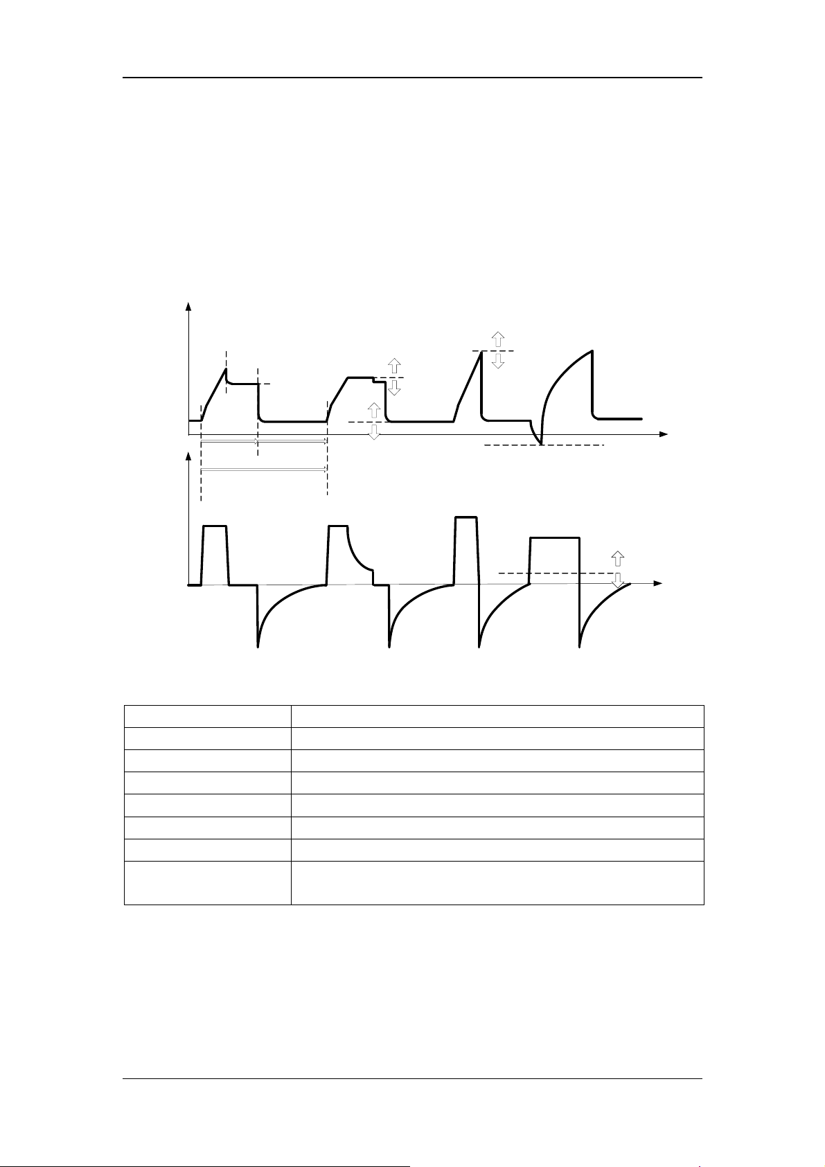
6.6.2 V-A/C
V-A/C is volume-assist/control ventilation mode. In V-A/C mode, a certain tidal volume is
delivered to the patient within a certain period of gas delivery time. During the expiratory
phase, V-A/C mode supports synchronization trigger. Namely, when the ventilator detects
patient inspiratory effort, it delivers next mechanical ventilation in advance.
The following figure shows typical waveforms in V-A/C mode.
Pressure
Paw high
alarm limit
Flow
Tpause(%) x Time of
Inspiration
Time
1/Breathing
frequency
inspiration
Expiration
Time
Paw high
alarm limit -5
PEEP
In V-A/C mode, you need to set the following basic ventilation parameters:
[O
%]:
2
[TV]:
[Tinsp] or [I:E]:
[f]:
[PEEP]:
[Assist]:
[F-Trig] or [P-Trig]:
[Tpause(%)] or [Flow]:
Oxygen concentration
Tidal volume
Inspiration time or ratio of inspiratory time to expiratory time
Breathing frequency
Positive end-expiratory pressure
Switching trigger ON/OFF
Inspiration trigger level
Percent of inspiratory pause time or flow delivered to the patient in
the inspiratory phase
Inspiration
trigger level
Time
Inspiration
trigger level
Time
6-10
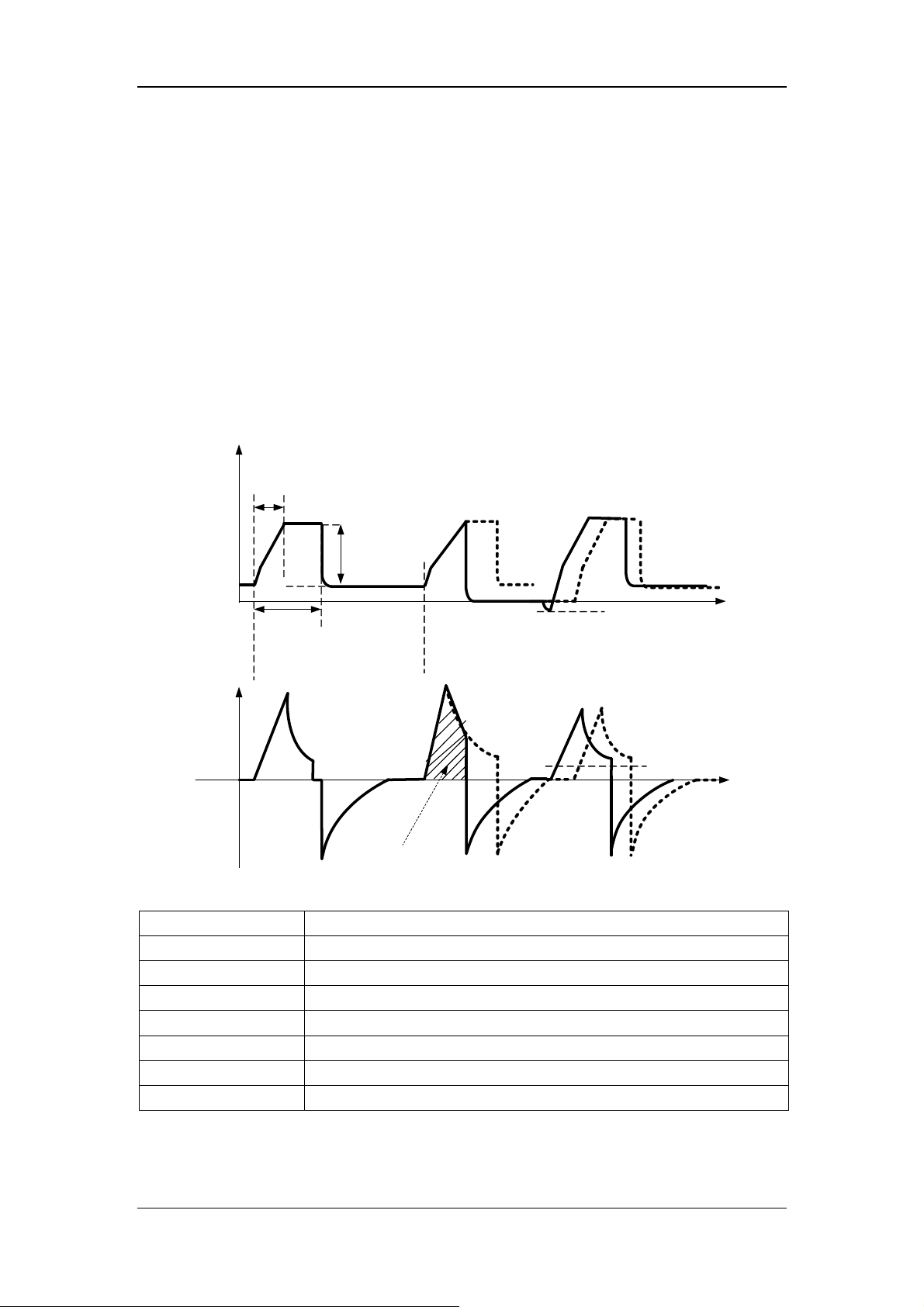
6.6.3 P-A/C
P-A/C is pressure-assist/control ventilation mode. In P-A/C, the patient’s airway pressure
rises to the preset pressure level within the time of pressure rising during the inspiration
phase, and is held at this level till inspiration time is completed. Then the system switches to
expiration. When the airway pressure is held at the preset pressure level, delivered gas flow
has decelerating shape, and varies with the resistance and compliance of the patient’s lungs.
During the inspiratory phase, when the volume of gas delivered exceeds the tidal volume
high alarm limit, the system switches to the expiratory phase immediately. During the
expiratory phase, synchronization trigger is supported. Namely, when the ventilator detects
patient inspiratory effort, it delivers next mechanical ventilation breath immediately.
The following figure shows typical waveforms in P-A/C mode.
Pressure
Rise time
△Pinsp
PEEP
Inspiration
Time
Flow
TV Overrange
In P-A/C mode, you need to set the following basic ventilation parameters:
[O
%]:
2
[△Pinsp]:
[Tinsp] or [I:E]:
[f]:
[PEEP]:
[Assist]:
[F-Trig] or [P-Trig]:
[Tslope]:
Oxygen concentration
Inspiratory pressure
Inspiration time or inspiratory/expiratory time ratio.
Breathing frequency
Positive end-expiratory pressure
Switching trigger ON/OFF
Inspiration trigger level
Time of pressure rising
Inspiration
trigger level
Time
Inspiration
trigger level
Time
6-11

r
6.6.4 V-SIMV
V-SIMV is volume-synchronized intermittent mandatory ventilation mode. It provides the
minimum number of mandatory breaths based on the preset intermittent mandatory
ventilation frequency. Mandatory ventilation mode is volume mode (V-A/C mode). If patient
triggers within the trigger window, ventilator delivers mandatory volume control breath once.
Mandatory volume control breath is also delivered once if it is not triggered at the end of
trigger window. Spontaneous breathing or pressure support breathing is supported outside the
trigger window. The duration of trigger window is 5s for adults and 1.5s for pediatrics and
neonates. If the expiratory time is less than the duration of trigger window, the trigger
window covers the expiratory time. The following figure shows typical waveforms in
V-SIMV+PSV mode.
V-SIMV+PSV
SIMV cycle
SIMV cycle
Paw
Flow
Trigger
window
Volume
control
Trigger
window
Volume
control
Trigger
window
In V-SIMV mode, you need to set the following basic ventilation parameters:
[O
%]:
2
[TV]:
[Tinsp]:
[fsimv]:
[Tpause(%)] or [Flow]:
Oxygen concentration
Tidal volume
Inspiration time
Mandatory breathing frequency
Percent of inspiratory pause time or flow delivered to the patient
during inspiration
[△Psupp]:
[PEEP]:
[F-Trig] or [P-Trig]:
[Exp%]:
[Tslope]:
Pressure support level
Positive end-expiratory pressure
Inspiration trigger level
Expiration trigger level
Time of pressure rising
△Psupp
Insp. trigge
Time
Time
6-12
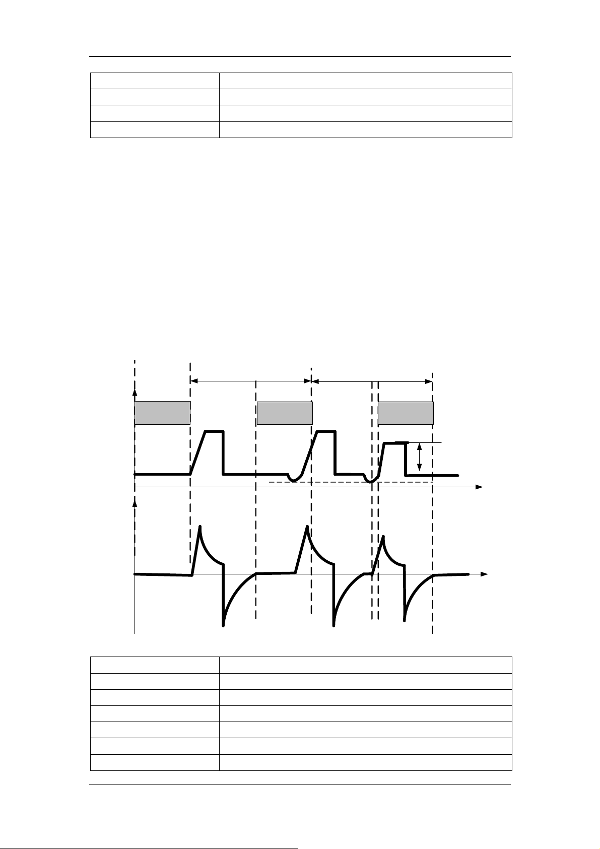
[Apnea Vent]:
[TVapnea] or [△Papnea]:
[fapnea]:
[Apnea Tinsp]:
Switch for apnea ventilation
Tidal volume or inspiration pressure in apnea ventilation cycle
Frequency of apnea ventilation
Inspiration time of apnea ventilation
6.6.5 P-SIMV
P-SIMV is pressure-synchronized intermittent mandatory ventilation mode. It provides the
minimum number of mandatory breaths based on the preset intermittent mandatory
ventilation frequency. Mandatory ventilation mode is pressure mode (P-A/C mode). If patient
triggers within the trigger window, ventilator delivers mandatory pressure control breath once.
Mandatory pressure control breath is also delivered once if it is not triggered at the end of
trigger window. Spontaneous breathing or pressure support breathing is supported outside the
trigger window. The duration of trigger window is 5s for adults and 1.5s for pediatrics and
neonates. If the expiratory time is less than the duration of trigger window, the trigger
window covers the expiratory time. The following figure shows typical waveforms in
P-SIMV+PSV mode.
P-SIMV+PSV
SIMV cycle
SIMV cycle
Paw
Flow
Trigger
window
Pressure
control
Trigger
window
Pressure
control
Trigger
window
In P-SIMV mode, you need to set the following basic ventilation parameters:
[O
%]:
2
[△Pinsp]:
[Tinsp]:
[fsimv]:
[Tslope]:
[PEEP]:
[Exp%]:
Oxygen concentration
Inspiratory pressure
Inspiration time
Mandatory breathing frequency
Time of pressure rising
Positive end-expiratory pressure
Expiration trigger level
△Psupp
Insp. trigger
Time
Time
6-13

[△Psupp]:
[F-Trig] or [P-Trig]:
[Apnea Vent]:
[TVapnea] or [△Papnea]:
[fapnea]:
[Apnea Tinsp]:
Pressure support level
Inspiration trigger level
Switch for apnea ventilation
Tidal volume or inspiration pressure in apnea ventilation cycle
Frequency of apnea ventilation
Inspiration time of apnea ventilation
6.6.6 CPAP/PSV
PSV is pressure support ventilation mode. The system delivers a PSV when it detects that
patient inspiratory effort reaches the preset inspiration trigger level. Time of pressure rising
and pressure support level are set by the user. At the beginning of inspiratory phase, the
patient’s airway pressure rises to the preset pressure level within the preset time of pressure
rising, and is held at this pressure level till patient inspiratory flow is detected to reach the
expiration trigger level. In PSV, when the airway pressure is held at the preset pressure level,
delivered gas flow decelerates, and varies with the resistance and compliance of the patient’s
lungs.
Pressure
Pressure
Support
Ventilation
Apnea Ventilation
Flow
Pressure
support
Inspiratory trigger
Expiration trigger
Inspiration trigger
Apnea time
Rise time
Apnea Tinsp
Apnea
Ventilation Cycle
Papnea
Time
Time
6-14
 Loading...