


Service Manual

Accutorr® is a registered trademark of Mindray DS USA, Inc.
Copyright © Mindray DS USA, Inc., 2009. Printed in U.S.A. All rights reserved. Contents of this publication may not be
reproduced in any form without permission of Mindray DS USA, Inc.
Masimo SET
®
Mindray
®
Nellcor
is a U.S. registered trademark of Tyco International Ltd.
SmarTemp
®
is a U.S. registered trademark of Masimo Corp.
is a trademark or a registered trademark of Shenzhen Mindray Bio-Medical Electronics Co., Ltd.
™
is a trademark of Shenzhen Mindray Bio-Medical Electronics Co., Ltd.
Accutorr V Service Manual 0070-10-0702

Tabl e of C on te nt s
Preface..........................................................................................................................................................v
Warnings, Cautions, and Notes .......................................................................................................................vii
Warnings ......................................................................................................................................................vii
Cautions ........................................................................................................................................................ viii
Notes ............................................................................................................................................................ x
Safety Designations......................................................................................................................................... x
Product Limitations ..........................................................................................................................................xi
Unpacking ..................................................................................................................................................... xi
Symbols and Descriptions ................................................................................................................................ xii
Theory of Operation ......................................................................................................... 1 - 1
Introduction.................................................................................................................................................... 1 - 2
Controls and Indicators....................................................................................................................................1 - 2
System Overview ............................................................................................................................................1 - 2
Hardware Structure.........................................................................................................................................1 - 4
Main Board ............................................................................................................................................ 1 - 5
Power Board........................................................................................................................................... 1 - 6
Key and Displays Board ...........................................................................................................................1 - 7
Parameter Boards ....................................................................................................................................1 - 8
Module .................................................................................................................................1 - 8
SpO
2
NIBP Module .................................................................................................................................. 1 - 9
Optional Temperature Module .......................................................................................................... 1 - 9
Recorder ................................................................................................................................................1 - 10
Bar Code Scanner ................................................................................................................................... 1 - 11
Specifications.................................................................................................................... 2 - 1
Introduction.................................................................................................................................................... 2 - 2
NIBP Measurement .........................................................................................................................................2 - 2
Blood Pressure ........................................................................................................................................2 - 2
Static Accuracy ....................................................................................................................................... 2 - 2
Maximum Cuff Pressure ............................................................................................................................2 - 2
Cuff Inflation ........................................................................................................................................... 2 - 3
Maximum Leakage ..................................................................................................................................2 - 3
Deflation Rate .........................................................................................................................................2 - 3
Update Period.........................................................................................................................................2 - 3
Initial NIBP Pressure Setup and Range........................................................................................................2 - 3
NIBP Measurement Cycle................................................................................................................................. 2 - 4
Cuff Inflation Time.................................................................................................................................... 2 - 4
Cuff Pressure Automatic Check Algorithm ...........................................................................................2 - 4
Automatically Adjusted Inflation Value after First Measurement...................................................................... 2 - 5
Pulse Rate............................................................................................................................................... 2 - 5
Measurement ........................................................................................................................................2 - 6
SpO
2
DPM SpO2 Module Performance............................................................................................................... 2 - 6
SpO2 ............................................................................................................................................ 2 - 6
Pulse Rate ....................................................................................................................................... 2 - 6
Alarm setting range .........................................................................................................................2 - 6
Masimo MS-2013 SpO
.............................................................................................................................................2 - 7
SpO
2
Pulse Rate ....................................................................................................................................... 2 - 8
Alarm Setting Range ........................................................................................................................ 2 - 8
Nellcor NELL-3 SpO
SpO2 ............................................................................................................................................ 2 - 9
Pulse Rate ....................................................................................................................................... 2 - 9
Alarm Setting Range ........................................................................................................................ 2 - 9
Performance........................................................................................................ 2 - 7
2
Performance............................................................................................................. 2 - 9
2
Accutorr V Service Manual 0070-10-0702 i

Tabl e of C on te nts
Temperature...................................................................................................................................................2 - 10
Display Area, Indicator, and Controller .............................................................................................................2 - 10
Display Area...........................................................................................................................................2 - 10
LCD ...............................................................................................................................................2 - 10
7-Segment Digit Display ...................................................................................................................2 - 10
Monochrome LED Indicator ............................................................................................................... 2 - 10
Power Indicator ...............................................................................................................................2 - 11
Overlay and labeling............................................................................................................................... 2 - 11
Alarm Lamp ............................................................................................................................................ 2 - 11
Keys ......................................................................................................................................................2 - 12
Patient Cable Connectors .........................................................................................................................2 - 13
Audio Indicator .............................................................................................................................................. 2 - 13
Pulse Tone Function.................................................................................................................................. 2 - 13
Multiple-Level Volume............................................................................................................................... 2 - 13
Real-time Clock............................................................................................................................................... 2 - 13
Standby Mode ............................................................................................................................................... 2 - 14
Alarm Information ........................................................................................................................................... 2 - 15
Basics ....................................................................................................................................................2 - 15
Alarm Notification ................................................................................................................................... 2 - 15
Audio Alarm Pause, Audio Alarm Off, and Audio Alarm Silencing ................................................................ 2 - 15
Configuration management.............................................................................................................................. 2 - 15
Barcode scanner.............................................................................................................................................2 - 15
Troubleshooting................................................................................................................ 3-1
Introduction.................................................................................................................................................... 3 - 2
Part Replacement ............................................................................................................................................ 3 - 2
Monitor Status Check ......................................................................................................................................3 - 2
Technical Alarm Check ....................................................................................................................................3 - 3
Troubleshooting Guide ....................................................................................................................................3 - 4
Power On/Off Failures ............................................................................................................................3 - 4
Display Failure ........................................................................................................................................ 3 - 4
LED Digital Display and Indication Lamp Failure ..........................................................................................3 - 4
Alarm Problems ......................................................................................................................................3 - 5
Key Failure ............................................................................................................................................3 - 5
Recorder Failures.....................................................................................................................................3 - 6
Interface Failures ....................................................................................................................................3 - 6
Power Supply Failures ..............................................................................................................................3 - 6
Network Related Problems .......................................................................................................................3 - 7
Software Upgrade Problems ....................................................................................................................3 - 8
Bar Code Scanner Failures .......................................................................................................................3 - 8
NIBP Measurement Failures ......................................................................................................................3 - 9
Measurement Failure ...................................................................................................................... 3 - 9
SpO
2
Temperature Measurement Failures ...........................................................................................................3 - 9
Repair and Disassembly ................................................................................................... 4 - 1
Tools ............................................................................................................................................................. 4 - 2
Preparation for Disassembly ............................................................................................................................. 4 - 2
Disassembly .................................................................................................................................................. 4 - 3
Separating the Front and Rear Halves of the Monitor ..................................................................................4 - 3
Disassembling the Front Housing Assembly ................................................................................................4 - 6
Removing the Main Rack Assembly............................................................................................................ 4 - 8
Removing NIBP Module ...........................................................................................................................4 - 11
Removing the Main (CPU) Board ..............................................................................................................4 - 12
Removing the Power Board.......................................................................................................................4 - 13
ii 0070-10-0702 Accutorr V Service Manual

Tabl e of C on te nt s
Removing the Battery Connector Assembly..................................................................................................4 - 13
Removing the Fan and Speaker .................................................................................................................4 - 14
Removing the Power Socket .....................................................................................................................4 - 15
Disassembling the Temperature Module......................................................................................................4 - 16
Disassembling SpO
Disassembling a DPM SpO
Disassembling a Masimo SpO
Disassembling a Nellcor SpO
Modules................................................................................................................... 4 - 17
2
module ..................................................................................................4 - 17
2
module ............................................................................................. 4 - 17
2
module ..............................................................................................4 - 18
2
Disassembling the NIBP Module ................................................................................................................4 - 19
Removing the NIBP Pump ................................................................................................................. 4 - 19
Removing the NIBP Dump Valve ........................................................................................................ 4 - 19
Removing the NIBP Bleed Valve ........................................................................................................ 4 - 20
Parts ................................................................................................................................5 - 1
Main Assembly...............................................................................................................................................5 - 2
Front Assembly ............................................................................................................................................... 5 - 3
Rear Housing Assembly ................................................................................................................................... 5 - 7
Main Bracket Assembly ...................................................................................................................................5 - 8
NIBP Assembly (Pump M6Q-100003- - -) ........................................................................................................... 5 - 10
NIBP Assembly (Pump 082-000056-00) ............................................................................................................5 - 13
Temperature Module Subassembly ....................................................................................................................5 - 16
Temperature Power Module Subassembly ..........................................................................................................5 - 18
Test and Calibration.......................................................................................................... 6 -1
Introduction.................................................................................................................................................... 6 - 2
Test Report..............................................................................................................................................6 - 3
Recommended Frequency .........................................................................................................................6 - 3
Visual Test...................................................................................................................................................... 6 - 4
Power-on Test ................................................................................................................................................. 6 - 4
NIBP Calibration............................................................................................................................................. 6 - 4
NIBP Accuracy Test......................................................................................................................................... 6 - 8
NIBP Leakage Test ...................................................................................................................................6 - 9
Test......................................................................................................................................................6 - 12
SpO
2
Test Under Normal Conditions .........................................................................................................6 - 12
SpO
2
Test in Motion Mode....................................................................................................................... 6 - 12
SpO
2
Summary of Test Methods.........................................................................................................................6 - 13
DPM SpO
Nellcor SpO
Masimo SpO
Testing the Optional Temperature Module.......................................................................................................... 6 - 14
Nurse Call Performance Test ............................................................................................................................6 - 16
Bar Code Scanner Test ....................................................................................................................................6 - 18
Electrical Safety Tests ...................................................................................................................................... 6 - 20
Enclosure Leakage Current Test .................................................................................................................6 - 20
Earth Leakage Current Test .......................................................................................................................6 - 20
Patient Leakage Current Test .....................................................................................................................6 - 21
Patient Auxiliary Leakage Current Test........................................................................................................ 6 - 21
Recorder Check ..............................................................................................................................................6 - 22
Software upgrade...........................................................................................................................................6 - 23
..................................................................................................................................... 6 - 13
2
................................................................................................................................. 6 - 13
2
................................................................................................................................. 6 - 13
2
Accutorr V Service Manual 0070-10-0702 iii

Tabl e of C on te nts
This page intentionally left blank.
iv 0070-10-0702 Accutorr V Service Manual

Preface Introduction
Preface
This manual provides detailed information about the assembling, disassembling, testing, and
troubleshooting of the equipment to support effective troubleshooting and repair. It is not
intended to be a comprehensive, in-depth explanation of the product architecture or technical
implementation. Observance of the manual is a prerequisite for proper equipment
maintenance and prevents equipment damage and personnel injury.
Refer to the Accutorr V Operating Instructions: P/N 0070-00-0699-XX for information for
operating this instrument.
This manual is based on the maximum configuration. Therefore, some contents may not be
applicable. For questions, contact Service.
This manual is for biomedical engineers, authorized technicians, or service representatives
responsible for troubleshooting, repairing, and maintaining the monitors.
Contents of this manual are subject to change without prior notice.
A password is required to access the service mode. The service password is 321.
The Accutorr V configurations are:
• Accutorr V with Nellcor® Pulse Oximetry—
includes NIBP, Nellcor SpO
• Accutorr V with Nellcor
includes NIBP, Nellcor SpO
a Trend Display, and Recorder
2,
®
Pulse Oximetry and SmarTemp™—
SmarTemp, a Trend Display, and Recorder
2,
• Accutorr V with Masimo SET® Pulse Oximetry—
includes NIBP, Masimo SpO2, a Trend Display, and Recorder
• Accutorr V with Masimo SET® Pulse Oximetry and SmarTemp™—
includes NIBP, Masimo SpO2, SmarTemp, a Trend Display, and Recorder
• Accutorr V with DPM Pulse Oximetry—
includes NIBP, DPM SpO2, a Liquid Crystal Display (LCD), and Recorder
• Accutorr V with DPM Pulse Oximetry and SmarTemp™—
includes NIBP, DPM SpO
SmarTemp, a Liquid Crystal Display (LCD), and Recorder
2,
All Accutorr V configurations can be upgraded with a barcode scanner.
Masimo Patents: This device (MASIMO SpO2 Module) is covered under one or more of the
following U.S. Patents 5,758,644, 5,823,950, 6,011,986, 6,157,850, 6,263,222,
6,501,975, and other applicable patents listed at: www.masimo.com/patents.htm.
Possession or purchase of this device does not convey any express or implied license to use
the device with replacement parts which would, alone, or in combination with this device,
fall within the scope of one or more of the patents relating to this device.
Accutorr V Service Manual 0070-10-0702 v

Introduction Preface
Nellcor Patents: This device (Nellcor SpO2 Module) is covered under one or more of the
following U.S. Patents Patent No. 5,485,847, 5,676,141, 5,743,263, 6,035,223,
6,226,539, 6,411,833, 6,463,310, 6,591,123, 6,708,049, 7,016,715, 7,039,538,
7,120,479, 7,120,480, 7,142,142, 7,162,288, 7,190,985, 7,194,293, 7,209,774,
7,400,919, and 7,212,847. Possession or purchase of this device does not convey any
express or implied license to use the device with replacement parts which would, alone, or in
combination with this device, fall within the scope of one or more of the patents relating to
this device.
vi 0070-10-0702 Accutorr V Service Manual

War nin gs, Ca uti ons , and Note s Introduction
Warnings, Cautions, and Notes
Read and adhere to all of the warnings and cautions listed throughout this manual.
A WARNING is provided to alert the user to potentially serious outcomes (death, injury or
serious adverse events) to the patient or the user.
A CAUTION is provided to alert the user that special care should be taken for the safe and
effective use of the device. They will include actions to be taken to avoid effects on patients
or users that will not be potentially life threatening or result in serious injury, but about which
the user should be aware.
A NOTE is provided when additional general information is available.
Warnings
WAR N I N G : I n t e r n al Electrical Sh o c k H azard - This unit does not contain
any user-serviceable parts. Do not remove instrument
covers. Refer servicing to qualified personnel. When the
integrity of the protective earth conductor, in the installation
or its arrangement, is in doubt, the equipment should be
operated from its internal battery. Observe all CAUTION and
WAR N I N G l a b e ls on the unit.
WAR N I N G : P o s s i ble explosion haz a r d . Do not operate m a c h i ne near
flammable anesthetic agents or other flammable
substances. Do not use flammable anesthetic agents (i.e.,
ether or cyclopropane.)
WAR N I N G : A l w ays place the u n i t o n a flat, rigid surface or onto a
WAR N I N G : To e n s u r e proper p e r fo r m an ce and safety an d t o p revent
WAR N I N G : U s e only cu f f s with ap p roved quick connect type connectors.
WAR N I N G : T h e A c c utorr V is not i n t e n d e d for use in a m a g n e t i c
WAR N I N G : D a n g e r of explosion i f battery is incorrectly replaced.
WAR N I N G : D o n o t u s e a damaged or broken unit or accessory.
Mindray approved stable mounting bracket.
the voiding of the warranty, only use authorized parts and
accessories with the Accutorr V. Use of unauthorized
accessories may result in erroneous readings.
resonance imaging (MRI) environment and may interfere
with MRI procedures.
Replace only with the same or equivalent type
recommended by the manufacturer. Dispose of used
batteries according to the manufacturers instructions and
local regulations. Batteries used in this de vice may present a
risk of fire or chemical burn if mistreated. Do not incinerate
battery, possible explosion may occur.
WAR N I N G : O p e r a tion of the A cc u torr V below the m i n i m um amplitude
or value of patient physiological signal may cause
inaccurate results.
Accutorr V Service Manual 0070-10-0702 vii

Introduction Cautions
WAR N I N G : U s e of a c cessories, transducers, and cables other than those
WAR N I N G : P e r f o r m t h e decontaminat i o n o r cleaning pro c ess with the
WAR N I N G : E l e c t ri cal safety tes t s a re a proven means of verifying the
WAR N I N G : C o m m e rcially availab l e t e s t equipment such as a safety
WAR N I N G : E l e c t ri cal safety tes t s s h ould meet the r e q u i r ements of the
WAR N I N G : T h e s e electrical saf e t y t ests do not su p e r s e d e local
WAR N I N G : A l l d evices using the A C m a i n s and connected t o medical
specified in the manual may result in increased
Electromagnetic Emissions or decreased Electromagnetic
Immunity of the Accutorr V. It can also cause delayed
recovery after the discharge of a cardiac defibrillator.
unit powered down and power cord removed.
electrical safety of the monitor. They are intended for
determining potential electrical hazards. Failure to identify
these hazards in a timely manner may cause personnel
injury.
analyzer can be used for electrical safety tests. Verify that
the test equipment can be safely and reliably used with the
monitor before use. The service personnel should acquaint
themselves with the use of the test equipment.
latest editions of EN 60601-1 and UL 60601.
requirements.
equipment within patient environments must meet the
requirements of the IEC 60601-1-1 medical electrical
systems standard and should be put under electrical safety
tests at the frequency recommended for the monitor.
Cautions
CAUTION: Observe extreme caution when a defibrillator is in use. Do
not touch any part of the patient, table, or monitor when a
defibrillator is in use. The Accutorr V should not be used
adjacent to or stacked with other equipment. If adjacent or
stacked use is necessary, the Accutorr V should be observed
to verify normal operation in the configuration in which it
will be used.
CAUTION: The unit should be checked periodically for obstructed vents.
CAUTION: At the end of their life, dispose of the Accutorr V,
CAUTION: When equipped with Nellcor
CAUTION: When equipped with MASIMO
If an obstruction is found, refer the unit to qualified service
personnel.
accessories, and single use supplies in accordance with local
regulations. Dispose of packaging waste in accordance with
local regulations.
®
oxygen transducers including Nellcor
dedicated adhesive sensors. Use of other oxygen
transducers may cause improper oximeter performance.
oxygen transducers including MASIMO LNOP
®
LNCS
patient dedicated adhesive sensors and MASIMO PC
Series Patient Cable. Use of other oxygen transducers may
cause improper Oximetry performance.
SpO2, use only Nellcor®
®
Oxisensor® patient
®
SpO2, use only MASIMO®
®
and MASIMO
viii 0070-10-0702 Accutorr V Service Manual

Cautions Introduction
CAUTION: Inaccurate readings may be caused by incorrect sensor
CAUTION: Route cables neatly. Ensure cables, hoses, and wires are
CAUTION: When cleaning sensors, do not use excessive amounts of
CAUTION: Recharge the Lithium ion battery while in the unit at room
application or use; significant levels of dysfunctional
hemoglobins (i.e. carbohemoglobins or methemoglobin); or
intra-vascular dyes such as indocyanine green or methylene
blue; exposure to excessive illumination, such as surgical
lamps (especially ones with a Xenon light source), bilirubin
lamps, fluorescent lights, infrared heating lamps, or direct
sunlight; excessive patient movement; venous pulsations;
electro-surgical interference; and placement of a sensor on
an extremity that has a blood pressure cuff, arterial
catheter, or intra-vascular line.
kept away from patient’s neck to avoid strangulation. Keep
floors and walkways free of cables to reduce risk to
hospital personnel, patients, and visitors. If the sensor or
patient cable is damaged in any way, discontinue use
immediately.
liquid. Wipe the sensor surface with a soft cloth, dampened
with the cleaning solution. To prevent damage, do not soak
or immerse the sensor in any liquid solution. DO NOT
ATTEMPT TO STERILIZE .
temperature. If using the Accutorr V in a hot environment,
the Lithium ion battery may not charge when the unit is
connected to the AC mains.
CAUTION: Remove the battery if the Accutorr V is not used for an
extended period of time.
CAUTION: The Communications Connectors on the Accutorr V are only
for use with IEC 60601-1-1 compliant equipment.
CAUTION: Never place fluids on top of this monitor. If fluid spills on the
unit, wipe clean immediately and refer the unit to qualified
service personnel.
CAUTION: Before disassembling the monitor, eliminate static charges.
CAUTION: Properly connect the cables or wires when reassembling the
CAUTION: All tests should be performed by qualified personnel only.
CAUTION: Disconnect the monitor from the patient and make sure that
When disassembling the parts labeled with static-sensitive
symbols, wear electrostatic discharge protection such as
antistatic wristband or gloves. Follow the correct sequence
to disassemble the monitor. Otherwise, the monitor may be
damaged permanently. Disconnect all the cables before
disassembling any parts. Take care not to damage any
cables or connectors.
monitor to avoid short circuit. When assembling the
monitor, select proper screws. If the wrong size screw is
tightened by force, the monitor may be damaged and the
screw or the part may not function as expected.
important data is saved before upgrading the monitor.
CAUTION: Do not shut down or power off the equipment when
upgrading the bootstrap program. Otherwise, it may cause
the equipment to break down.
Accutorr V Service Manual 0070-10-0702 ix

Introduction Notes
CAUTION: Program upgrades should be performed by qualified
service personnel only.
Notes
NOTE: The Accutorr V should be operated only by trained and
qualified personnel.
NOTE: Use disposable and single use accessories only once.
NOTE: Place the equipment in a location where the screen can
easily be seen and the operating controls can easily be
accessed.
NOTE: The instructions in this manual are based on the maximum
configuration.
NOTE: The optional Temperature module kit must be installed only
by trained personnel, and proper ESD prevention methods
must be followed.
NOTE: Only devices specified by Mindray DS USA, Inc. shall be
connected the RS-232 port
NOTE: When the RS-232 connector is used for DIAP, barcode power
must be set to OFF.
NOTE: Disconnect the Accutorr V from the mains to isolate it from
the mains power during an emergency.
Safety Designations
Safety designations per IEC 60601-1 Standard:
Type of protection against electric sho ck Class 1 with internal electric power source.
Where the integrity of the external protective
earth (ground) in the installation or its
conductors is in doubt, the equipment shall be
operated from its internal electric power
source.
Degree of protection against electric shock Monitor - Type B applied part.
NIBP - Type BF defibrillation protected
applied part.
SpO
- Type BF protected applied part.
2
Temp - Type BF protected applied part.
Supply Connection 100 – 240 V
50/60 Hz
0.85 – 0.5 A
Mode of Operation Continuous
AC
x0070-10-0702Accutorr V Service Manual

Product Limitations Introduction
Protection Against Hazard of Explosion Not Protected (Ordinary)
Protection Against Ingress of Liquids IPX1
Degree of Electrical Connection Between
Equipment and Patient
Degree of Mobility Portable
Equipment designed for direct electrical and
non-electrical connection to the patient.
Product Limitations
Non-invasive blood pressure (NIBP) accuracy depends on the application of the proper cuff
size. See Chapter 3.0 of the Operating Instructions for detailed information.
The Accutorr V will not operate effectively on patients who are experiencing convulsions or
tremors.
The Accutorr V is a portable device intended for intra-hospital use.
If the pressure cuff is not placed at the patient’s heart level, the NIBP measurement may be
subject to error, due to the hydrostatic effect.
The pulse rate data displayed on the Accutorr V is computed from the measurement of
peripheral pulses (peripheral pulses taken only during a measurement cycle). The rate
measured by the Accutorr V may differ from the rate of an ECG monitor. This is because the
ECG is an electrical signal that may not always result in a peripheral pulse.
Administration of certain vasoconstrictor drugs (for example, norepinephrine), may reduce
peripheral perfusion to a level that prevents the Accutorr V from taking pulse rate
measurements.
Arterial compression, tricuspid regurgitation, or other conditions may reduce perfusion to a
level that prevents the Accutorr V from taking pulse rate measurements.
The presence of arrhythmias may increase the time required to complete a measurement and
may extend this time so that a measurement cannot complete.
The Accutorr V is not intended for use during CPR. The monitor uses an oscillometric
technique based on normal peripheral circulation to compute blood pressure.
Unpacking
Remove the instrument from the shipping carton and examine it for signs of shipping
damage. Save all packing materials, invoice, and bill of lading. These may be required to
process a claim with the carrier. Check all materials against the packing list. Contact the
Customer Service Department (800) 288-2121 or (201) 265-8800 for prompt assistance in
resolving shipping problems.
NOTE: The Accutorr V should only be shipped in its original
Accutorr V Service Manual 0070-10-0702 xi
packing materials to avoid shipping damage.
Introduction Symbols and Descriptions
T1
SpO
2
REF
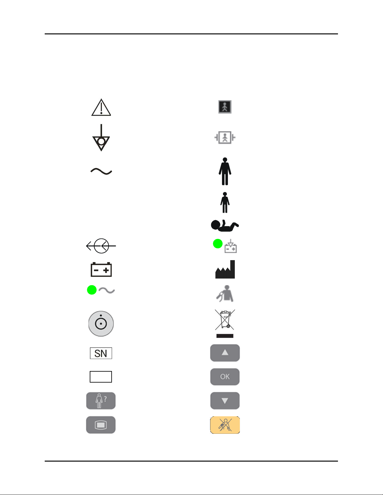
Symbols and Descriptions
SYMBOL DESCRIPTION SYMBOL DESCRIPTION
Attention, Consult
Accompanying Documents /
Refer to Manual
Type BF Equipment
Equipotentiality
Equipotential grounding
Alternating Current (AC) Adult
Predictive Thermometer
Connector
SpO
Connector Neonate
2
Electrical connectors Operating on battery power
Battery Manufacturer
Connected to AC mains
Defibrillator-proof Type BF
Equipment
Pediatric/Child
NIBP Connector
Power On/Off – Standby Recycle
Serial number Up key
Part Number Confirm key
Patient Information key Down key
Main menu key Deflate Cuff key
xii 0070-10-0702 Accutorr V Service Manual
Symbols and Descriptions Introduction
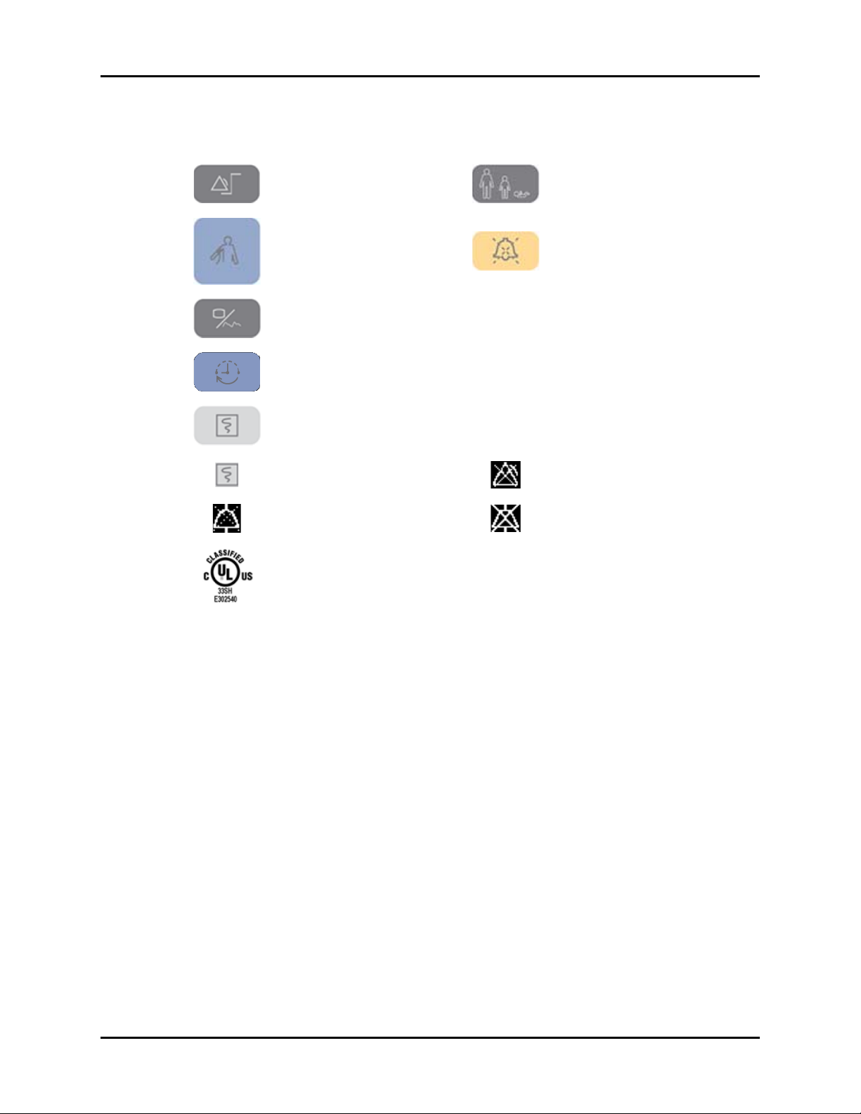
SYMBOL DESCRIPTION SYMBOL DESCRIPTION
Set alarms key Patient Size key
Start NIBP key Alarm Silence key
Display Tabular Trends/Pleth
Wav e
NIBP interval key SP1
NC1 Nurse Call connector
RS-232 connector
(Serial Port 1)
Print key (front panel) CS1 Network connector
Print key (recorder)
Alarm Silenced indicator on
LCD display
Alarm Disabled indicator on
LCD display
Audio Alarm Off indicator on
LCD display
Classified by Underwriters Laboratories Inc. with respect to electric shock, fire and
mechanical hazards, only in accordance with UL 60601-1, CAN/CSA C22.2
NO.601-1, IEC 60601-1-1, IEC 60601-2-30, IEC 60601-2-49.
Accutorr V Service Manual 0070-10-0702 xiii

Introduction Symbols and Descriptions
This page intentionally left blank.
xiv 0070-10-0702 Accutorr V Service Manual

1.0
Theory of Operation
Introduction.................................................................................................... 1-2
Controls and Indicators ................................................................................... 1-2
System Overview............................................................................................ 1-2
Hardware Structure......................................................................................... 1-4
Accutorr V Service Manual 0070-10-0702 1 - 1
Introduction Theory of Operation
MAIN UNIT
RECORDER
BATTERY
CHAMBER
TEMP
MODULE
CHAMBER
MAIN BOARD
POWER
BOARD
KEY &
DISPLAY
PARAMETER
BOARDS
RECORDER
BOARD
BARCODE
SCANNER
SYSTEM
SOFTWARE
PARAMETER
SOFTWARE
UPGRADE
SOFTWARE
PRINT
SOFTWARE
GATEWAY
SOFTWARE
BARCODE
SCANNER
SUPPORT
SYSTEM
HARDWARE
MECHANICAL
SOFTWARE
1.1 Introduction
The Accutorr V monitors the following patient vital signs: non-invasive blood pressure (NIBP),
pulse oxygen saturation (SpO2), pulse rate (PR), and temperature (Temp) for a single adult,
pediatric, or neonatal patient. Temperature is measured using the optional Temperature
Module.
1.2 Controls and Indicators
For information on controls, connectors, and indicators, refer to the Accutorr V Operating
Instructions, Part Number 0070-10-0699-02.
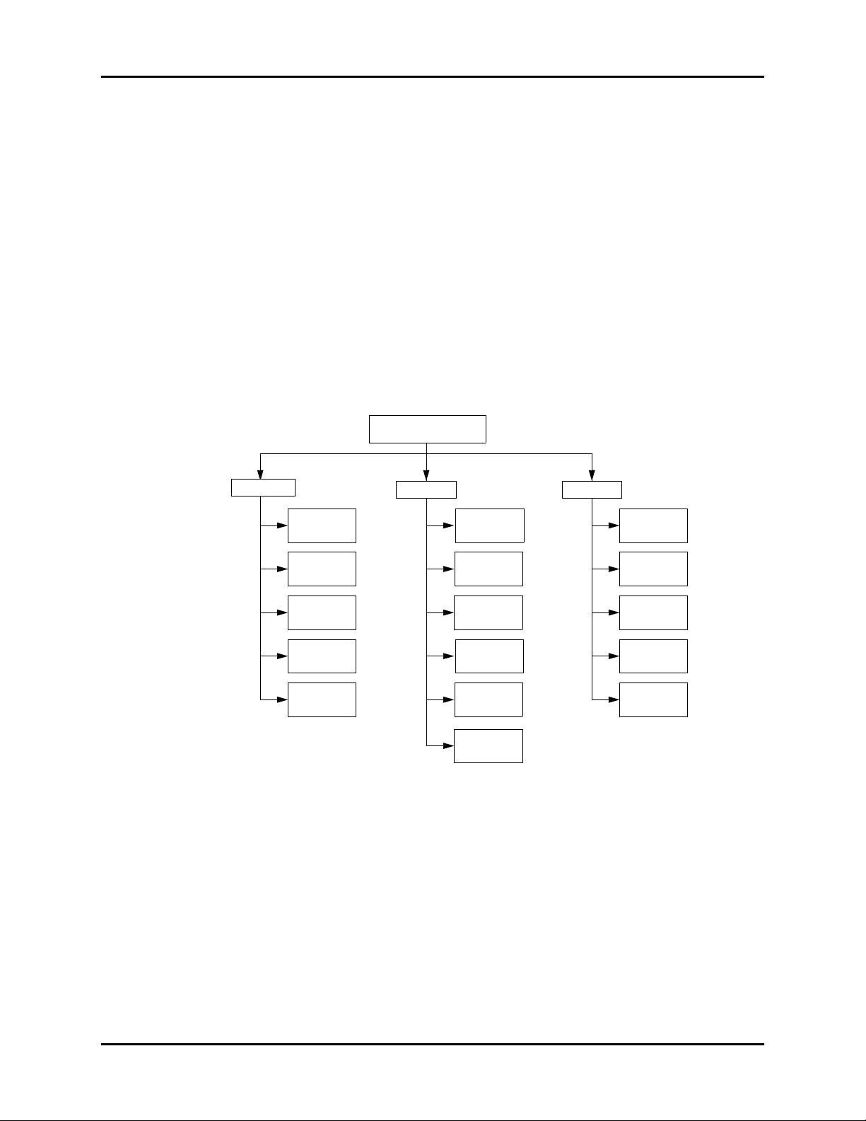
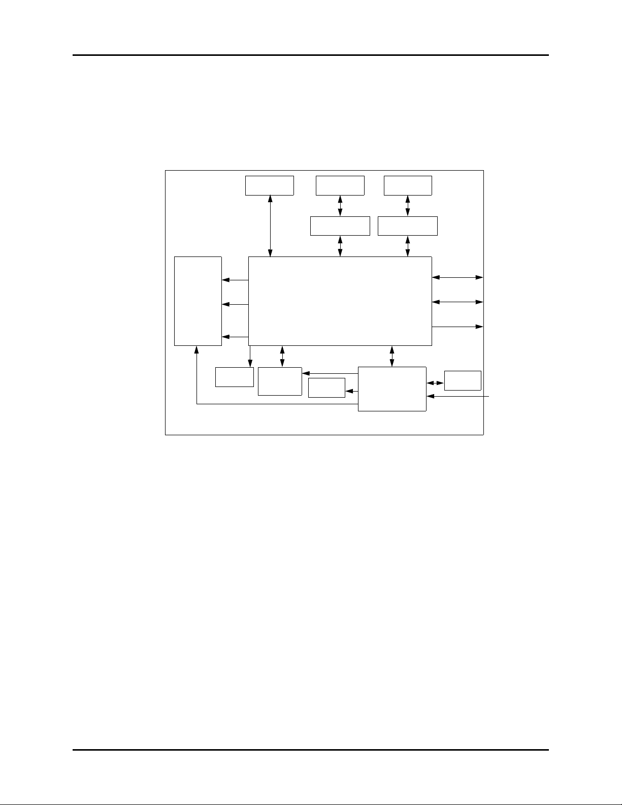
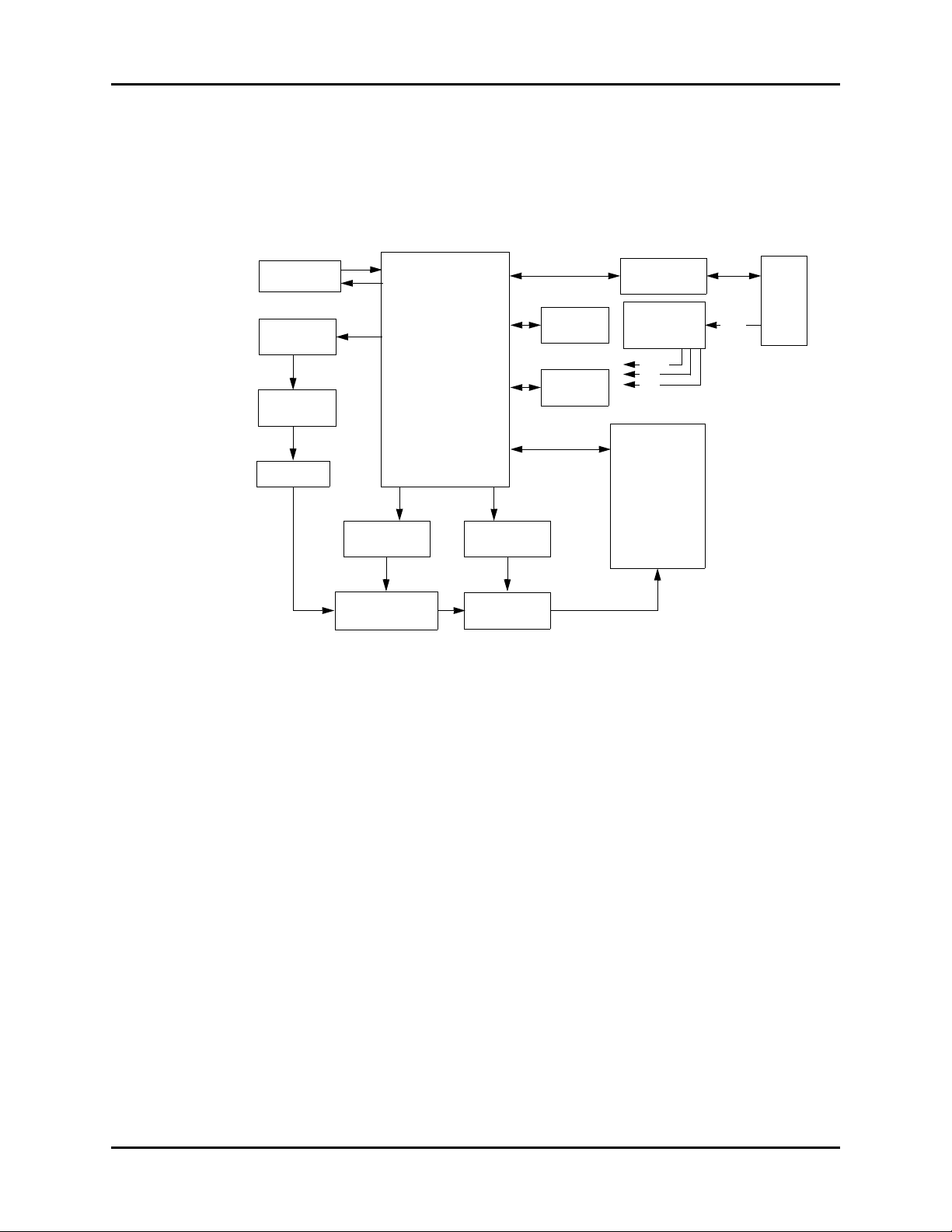
1.3 System Overview
FIGURE 1-1 shows the relationship of the Accutorr V monitoring system’s mechanical,
hardware, and software components.
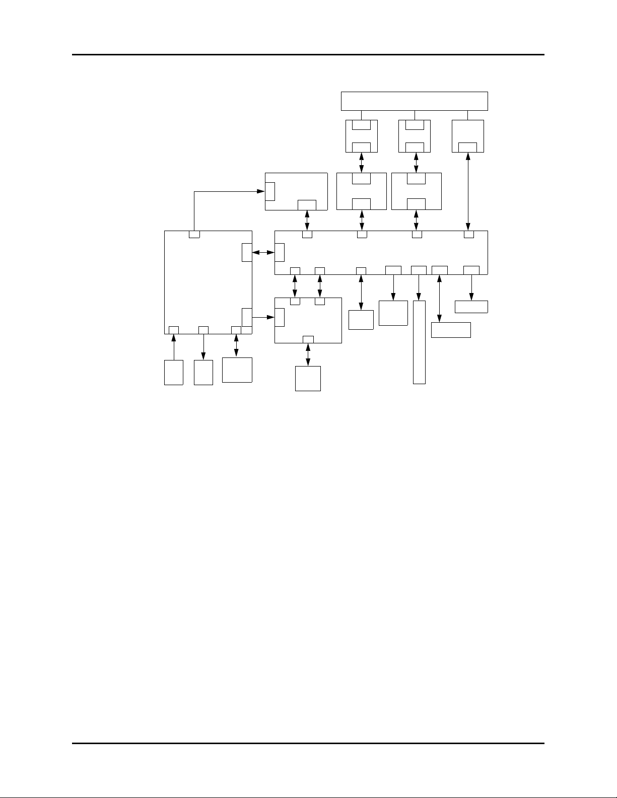
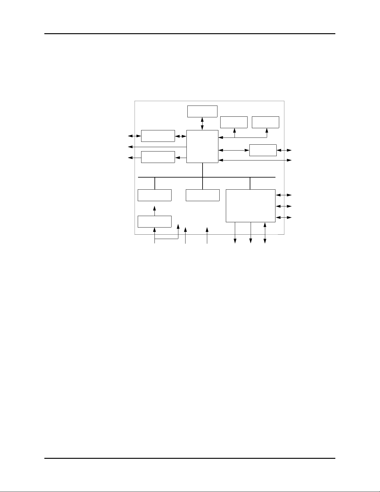
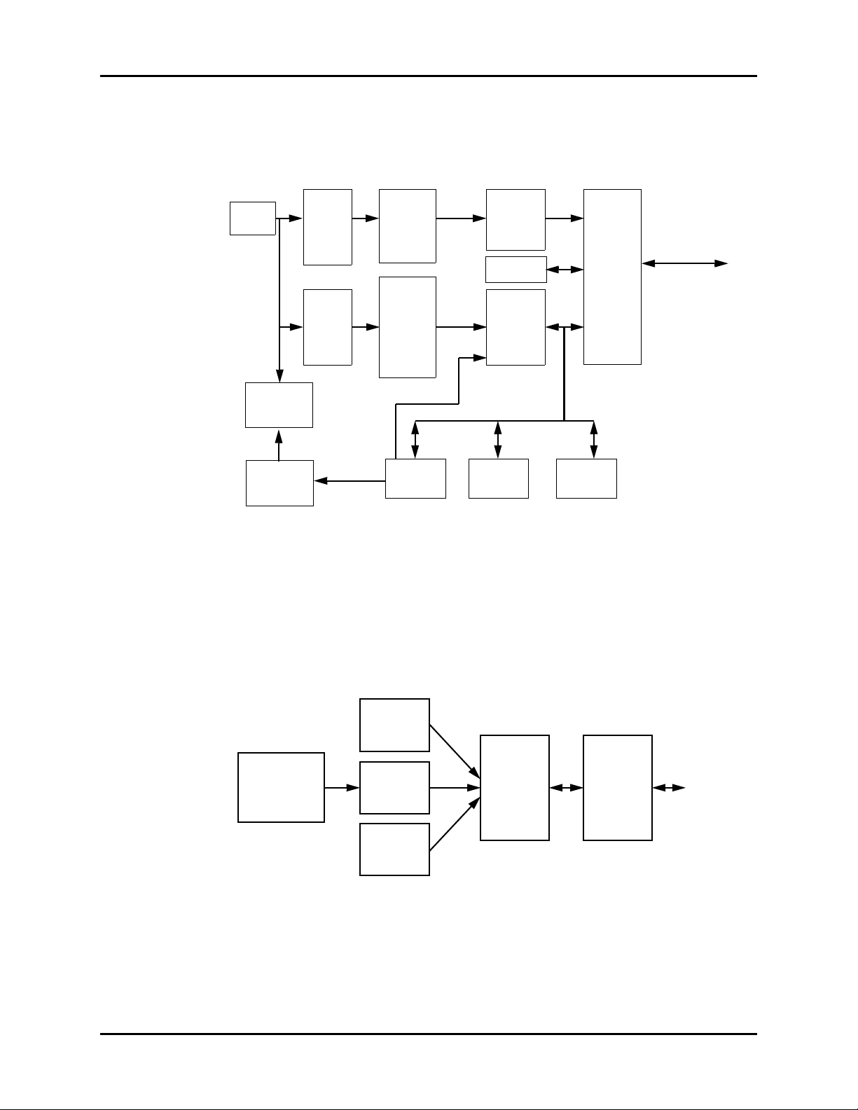
FIGURE 1-2 shows the Accutorr V monitoring system’s PC board connections.
1 - 2 0070-10-0702 Accutorr V Service Manual
FIGURE 1-1 System Mechanical, Hardware, and Software Overview
Theory of Operation System Overview
J10
J3
J2
J1
J4
J6
J2
P1
P2
J2
J1
J1
P5
J6
J2
J2
J7
J8 J9
J2 J3 J4 J5
J11 J12 J13
P3 P4
P2
J4 J5
POWER
RECORDER
SpO
2
TEMP
NIBP
ISOLATION
POWER BOARD
MAIN BOARD
PAR AM ETER RECE PTAC LE
KEY & DISPLAY
BOARD
AC
INLET
FAN
BATTERY
LCD
BDM
PORT
SPEAKER
NETWORK CONNECTOR
NURSE CALL
RS232
J3
J4
ISOLATION
POWER BOARD
FIGURE 1-2 The System PCBA Connections
Accutorr V Service Manual 0070-10-0702 1 - 3
Hardware Structure Theory of Operation
ACCUTORR V
ISOLATION
POWER BOARD
TEMP MODULE
SpO
2
MODULE
NIBP MODULE
FAN
RECORDER
SPEAKER
KEY &
DISPLAY
BOARD
BATTERY
AC
NURSE CALL
RS232
ETHERNET
MAIN BOARD
POWER BOARD
COMMUNICATIONS
/POWER SUPPLY
ISOLATION
POWER BOARD
POWER
SUPPLY
LED &
KEY
LCD
COMMUNICATIONS
/POWER SUPPLY
1.4 Hardware Structure
FIGURE 1-3 shows the Accutorr V’s Hardware Structure. The core of the system is the main
board, which supplies power for all parameter modules. The parameter modules directly
communicate with the main board. The the main board processes measurements and the
status of all modules, and displays them through the key and display board.
FIGURE 1-3 The Accutorr V’s Hardware Structure
NOTE: The SpO2 isolation power board does not apply to models
with DPM Pulse Oximetry.
1 - 4 0070-10-0702 Accutorr V Service Manual
Theory of Operation Hardware Structure
CPU
WATCHDOG
PHY RTL8201
RTC E2 PROM
RS232 IC
FLASHSDRAM
LINEAR POWER
AUDIO PROCESS
CIRCUIT
FPGA
NURSE CALL
ETHERNET
SPEAKER
3.3V LCD
1.5V
5.0V 12V LED KEY
SERIAL PORT 0
RS232
SERIAL PORT 1:
NIBP
SERIAL PORT 2:
SpO
2
SERIAL PORT 3:
TEMP
SERIAL PORT 4:
RECORDER
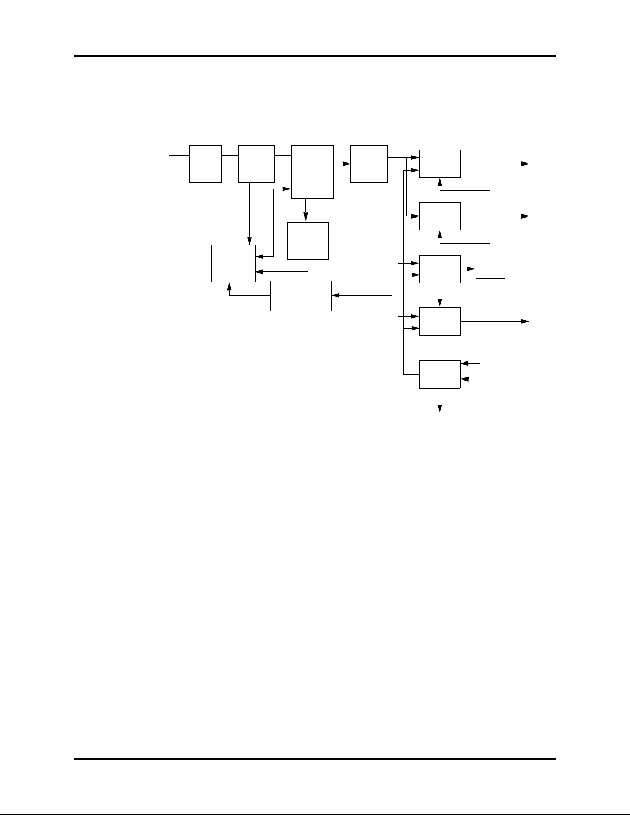
1.4.1 Main Board
FIGURE 1-4 shows the main board, which provides resources and support for the overall
system. It controls the LCD, LED, keyboard, speaker, and recorder. It also communicates with
parameter modules and connectors. The main board also controls communication with the
speaker, the recorder, and all external connectors.
FIGURE 1-4 Main Board Principle Diagram
The main board communicates with all parameter modules and the recorder through an
FPGA extended serial port.
The main board supplies information using FPGA to the key and display board. It drives the
display, detects the keys, and implements the user interface.
The main board controls the alarm indicator using FPGA.
The main board controls the speaker to give audible alarms, key tones, and Pitch Tone.
The main board provides the nurse call connection, network connection, and R232
connection.
The real-time clock is implemented by the RTC chip. The RT clock is powered by the AC
mains, battery, or button cell on the main board. The button cell ensures the continuous
working of the clock in the event that the AC mains and batteries are not available.
Accutorr V Service Manual 0070-10-0702 1 - 5
SDRAM stores running program instructions and data temporarily. The system memory and
trend data memory is flashed. The device configuration memory is EEPROM.
Hardware Structure Theory of Operation
AC
INPUT
EMI
FILTER
RECTIFIER
& FILTER
RECTIFIER
& FILTER
FLYBACK
CONVERTER
CURRENT
DETECTION
PMW
CONTROLLER
BATTERY
CHARGING
CIRCUIT
DC/DC
CONVERTER
COUPLER
FEEDBACK &
ISOLATION
CIRCUIT
DC/DC
CONVERTER
SWITCH
CIRCUIT
DC/DC
CONVERTER
16.8V
12V
OUTPUT
5V
OUTPUT
3.3V
OUTPUT
0VP&0CP
0VP&0CP
0VP&0PP
PCON
1.4.2 Power Board
The power board, shown in FIGURE 1-5, converts the input power (AC mains or battery) to
different working voltages for other boards. It also charges the battery.
FIGURE 1-5 Power Board Principle Diagram
The AC flows through the EMI filter and the rectifier and filter. The rectifier and filter converts
the AC to 16.8V DC voltage by the Flyback converter. The 16.8V DC voltage is the main
input to the DC/DC converters and charging circuit. The DC/DC converters convert 16.8V
DC to 12V, 5V, and 3.3V DC. The charging circuit charges the lithium battery. When the
Accutorr V is not connected to the AC mains, the battery supplies power to the DC/DC
converters.
The 16.8V DC output is protected against over-voltage and over-power. The 12V, 5V, and
3.3V DC outputs are protected against over-voltage, short-circuit, and over–current.
1 - 6 0070-10-0702 Accutorr V Service Manual
Theory of Operation Hardware Structure
3.3V
DISABLE
LED
FSTN LCD
MODULE
LCD
SIGNAL
ADV
3.3V
VSB
KEY MATRIX
CPLD
START-UP
CIRCUIT
Switch
DETECTION
LED&KEY
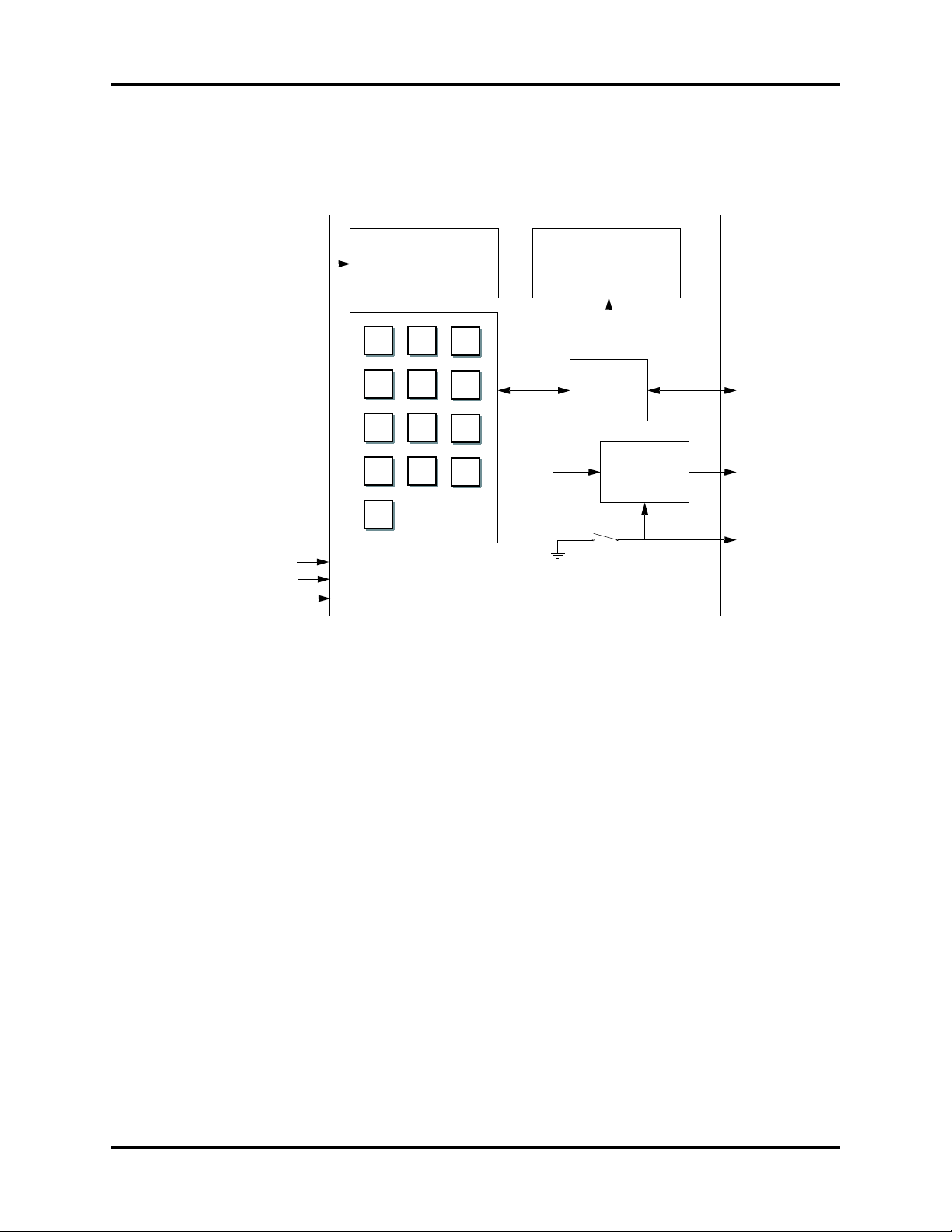
1.4.3 Key and Displays Board
The key and displays board, shown in FIGURE 1-6, provides the user interface. The board
contains the LCD module, 7-segment digital display, LED indication lamp, and keys.
FIGURE 1-6 Key and displays Board Principle Diagram
The LCD module adjusts contrast and brightness.
The 7-segment digit units display parameter data.
The AC indicator is driven by the ADV output from the power board, and the working status
indicator (built in the Power On/Off key) is driven by 3.3V voltage. The battery indicator is
jointly controlled by the flash control signal, ADV signal, and VBC signal.
The keypad contains the power ON/OFF key and the other 13 function keys.
Accutorr V Service Manual 0070-10-0702 1 - 7
Hardware Structure Theory of Operation
HOST
ISOLATED SERIAL
IN/OUTPUT PORT
4KV ISOLATED
POWER SUPPLY
+3.3V
+5V
-5V
+12V
CPU
/RST
WDI
DRAM
FLASH
A/D
CONVERTER
OFFSET DAC
OFFSET
AMPLIFIER
WATCHDOG
DRIVE DAC
LED DRIVE
CIRCUITRY
SENSOR
GAIN CONTROL
CIRCUITRY
PROGRAMMABLE
GAIN CIRCUITRY
1.4.4 Parameter Boards
1.4.4.1 SpO
FIGURE 1-7 shows the SpO2 module parameter board diagram.
Module
2
FIGURE 1-7 SpO
The SpO
sensor collects the pulsing red and infrared light signals transmitting through the
2
Module Principle Diagram
2
finger or toe, and processes the collected signals to create the measured result. The SpO2
module controls the LED drive circuit and the amplifying circuit gain corresponding to the
finger or toe perfusions and transmittances.
1 - 8 0070-10-0702 Accutorr V Service Manual
Theory of Operation Hardware Structure
CUFF
PRESSURE
SENSOR
PRESSURE
SENSOR
FOR
PROTECT
PRESSURE
SIGNAL
AMPLIFIER
CIRCUITS
PRESSURE
SIGNAL
AMPLIFIER
CIRCUITS
FOR
PROTECT
CPU
ASYCHRONOUS
SERIAL
COMMUNICATION
WATCHDOG
OVER
PRESSURE
PROTECT
CIRCUIT
A/D
CONVERTER
PRESSURE
SIGNAL
MOTOR CONTROL
FEEDBACK SIGNAL
PUMP AND
VALVE
CONTROL
CIRCUIT
FLASH DRAM
MANIFOLD
VALV ES
AND PUMP
TEMPERATURE
DETECT
CIRCUIT
PROBE
RECOGNIZE
CIRCUIT
A/D
CIRCUIT
PROBE
HEAT
CIRCUIT
CPU SYSTEM
(ROM & RAM
WATCHDOG)
POWER
&
SIGNAL
ISOLATE
CIRCUIT
MAIN
BOARD
1.4.4.2 NIBP Module
FIGURE 1-8 shows the NIBP module parameter board diagram.
FIGURE 1-8 NIBP Module Principle Diagram
The Accutorr V calculates NIBP values using the oscillometric method of noninvasive blood
pressure measurement. These measurements correspond to comparisons with auscultatory
values, measured using the fifth Korotkoff sound within ANSI/AAMI SP10 standards for
accuracy.
1.4.4.3 Optional Temperature Module
FIGURE 1-9 shows the Temperature module parameter board diagram.
FIGURE 1-9 Optional Temperature Module Principle Diagram
The Temperature Module uses a thermistor as a sensor for measuring temperature. The
resistance of a given thermistor is nonlinearly relative to the temperature. The Temperature
Module measures the resistance of the thermistor and converts it into temperature.
Accutorr V Service Manual 0070-10-0702 1 - 9

Hardware Structure Theory of Operation
1.4.5 Recorder
The recorder receives data from the main board and sends it to the thermal printhead for
printing. It has a button to start or stop printing and a green LED to indicate the presence or
absence of paper.
1 - 10 0070-10-0702 Accutorr V Service Manual

Theory of Operation Hardware Structure
1.4.6 Bar Code Scanner
The bar code scanner reads one-dimensional and two-dimensional bar codes to simplify
admitting a patient. The bar code scanner communicates with the monitor. The serial port
supplies it with power. The scanner’s serial port is defined in the following table:
PIN DEFINITION
2Barcode_RX
3Barcode_TX
5GND
9VCC5VDC
The monitor’s serial port is defined in the following table:
PIN DEFINITION
2Monitor_TX
3Monitor_RX
5GND
9VCC5VDC
Basic settings of the bar code scanner are listed in the following table:
HOST PARAMETERS BAR CODE SCANNER FACTORY DEFAULT
Baud Rate 9600 9600
Data Bits 8 8
Stop Bits 1 1
Calibration bit 0 0
Handshaking None None
USER PARAMETERS BAR CODE SCANNER FACTORY DEFAULT
Beeper Tone Medium Medium
Beeper Volume Medium High
Trigger Mode Level Auto Aim
Parameter Scanning Disable Enable
DATA FORMAT BAR CODE SCANNER FACTORY DEFAULT
Prefix Value 7013 <CR><LF> 7013 <CR><LF>
Suffix 1 Value
Suffix 2 Value
Scan Data Transmission Format <PREFIX><DATA><SUFFIX 1><SUFFIX 2> Data only
7013 <CR><LF> 7013 <CR><LF>
Accutorr V Service Manual 0070-10-0702 1 - 11
Hardware Structure Theory of Operation
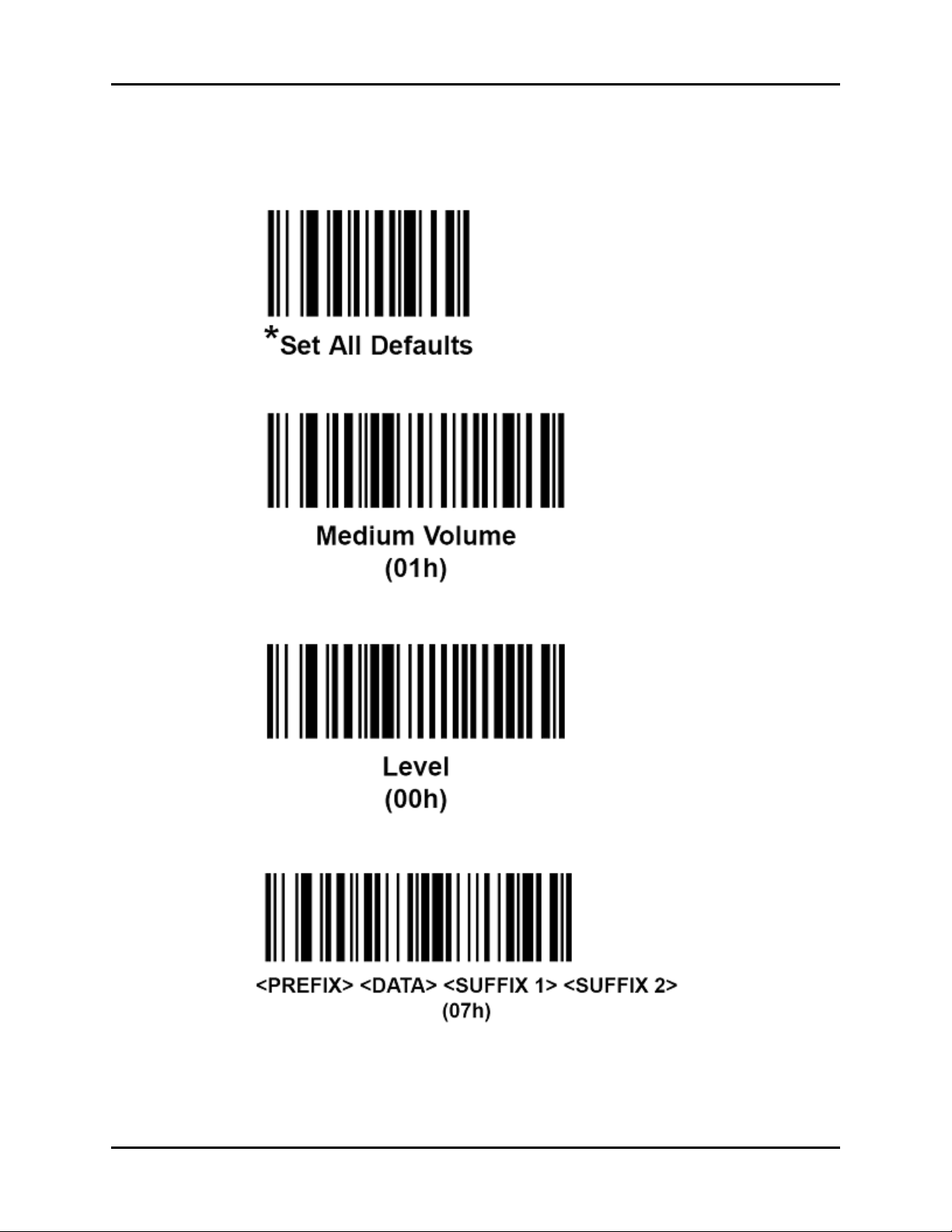
To ch an ge p ar am et er s et ti ng s, s ca n the following bar codes in sequence.
1. Set parameter defaults:
2. Set beeper volume:
3. Set trigger mode:
4. Set scan data transmission format:
1 - 12 0070-10-0702 Accutorr V Service Manual
Theory of Operation Hardware Structure
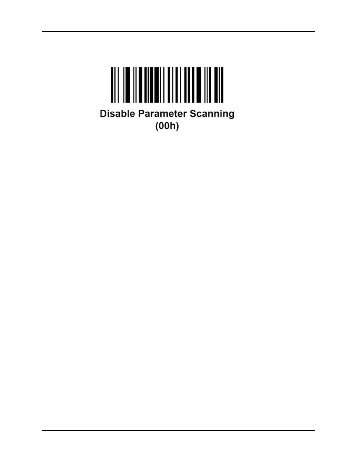
5. Disable parameter scanning:
Accutorr V Service Manual 0070-10-0702 1 - 13

Hardware Structure Theory of Operation
This page intentionally left blank.
1 - 14 0070-10-0702 Accutorr V Service Manual

2.0
Specifications
Introduction.................................................................................2-2
NIBP Measurement ......................................................................2-2
NIBP Measurement Cycle .............................................................2-4
SpO2 Measurement.....................................................................2-6
Tem per at ur e .. .. .. .. .. .. .. .. .... .. .. .. .. .. .. .. .. .. .. .. .. .. .. .. .. .. .... .. .. .. .. .. .. .. .. .. .. .. 2-1 0
Display Area, Indicator, and Controller ..........................................2-10
Audio Indicator ...........................................................................2-13
Real-time Clock ...........................................................................2-13
Standby Mode ............................................................................2-14
Alarm Information........................................................................2-15
Configuration management ..........................................................2-15
Barcode scanner .........................................................................2-15
Accutorr V Service Manual 0070-10-0702 2 - 1

Introduction Specifications
2.1 Introduction
The Accutorr V monitors patient vital signs (including non-invasive blood pressure (NIBP),
pulse oxygen saturation (SpO2), and pulse rate (PR)) for a single adult, pediatric, or neonatal
patient. It also monitors oral or rectal mode temperature (Temp) for a single adult or pediatric
patient; or axillary mode temperature for a single neonate, adult, or pediatric patient using
the optional Temperature Module.
2.2 NIBP Measurement
The NIBP module is used to measure the systolic pressure, diastolic pressure, and mean
pressure in the neonatal, pediatric, and adult modes. The Accutorr V calculates NIBP values
using the oscillometric method of noninvasive blood pressure measurement. These
measurements correspond to comparisons with auscultatory values, measured using the fifth
Korotkoff sound within ANSI/AAMI SP10 standards for accuracy.
2.2.1 Blood Pressure
PARAMETER PATIENT SIZE RANGE
Systolic pressure measurement Adult
Pediatric
Neonate
Diastolic pressure measurement Adult
Pediatric
Neonate
Mean pressure measurement Adult
Pediatric
Neonate
Measurement accuracy Mean error: <±5 mmHg
Standard deviation: <±8 mmHg
Measurements outside of the stated ranges are not guaranteed to be accurate.
55 – 235 mmHg
55 – 160 mmHg
45 – 120 mmHg
30 – 200 mmHg
30 – 150 mmHg
20 – 100 mmHg
30 – 235 mmHg
30 – 160 mmHg
20 – 120 mmHg
2.2.2 Static Accuracy
Measurement range: 0 – 300 mmHg
Static pressure measurement accuracy: ±3 mmHg
2.2.3 Maximum Cuff Pressure
Normal Use Over Pressure Protection
In normal use, the over-pressure detection is controlled by software. Once the cuff pressure
exceeds the threshold, the software enables the system to deflate the cuff.
Adult 300 mmHg
Pediatric 200 mmHg
Neonate 150 mmHg
2 - 2 0070-10-0702 Accutorr V Service Manual

Specifications NIBP Measurement
Single Fault Over-pressure protection
In single fault conditions, the hardware controls the cuff deflation to prevent the cuff
pressure from exceeding the following ranges:
Adult 330 mmHg
Pediatric 220 mmHg
Neonate 165 mmHg
2.2.4 Cuff Inflation
The Non-Invasive Blood Pressure inflation source brings a volume of 200 ccs to a pressure of
300 mmHg in less than or equal to 10 seconds
2.2.5 Maximum Leakage
The Non-Invasive Blood Pressure Cuff driver allows a pressure drop to be, at most, 1 mmHg
in 10 seconds as measured with a 200 cc volume at differential pressures of 250 mmHg,
150 mmHg, and 50 mmHg.
2.2.6 Deflation Rate
The Non-Invasive Blood Pressure Cuff venting mechanism in adult mode vents a volume of
500 cc, reduced from a pressure of 260 mmHg to a pressure of 15 mmHg in a maximum of
10 seconds.
The Non-Invasive Blood Pressure Cuff venting mechanism in neonatal mode vents a volume of
500 cc, reduced from a pressure of 150 mmHg to a pressure of 5 mmHg in a maximum of
5 seconds.
2.2.7 Update Period
The Non-Invasive Blood Pressure Parameter has an update period of one (1) second.
2.2.8 Initial NIBP Pressure Setup and Range
The initial pressure is adjustable, and should be set to the following default values:
PATIENT TYPE DEFAULT INITIAL PRESSURE ADJUST RANGE
Adult 180 mmHg 100 – 280 mmHg
Pediatric 140 mmHg 60 – 180 mmHg
Neonate 100 mmHg 40 – 120 mmHg
Manual pressure changes in increments of 5 mmHg.
Accutorr V Service Manual 0070-10-0702 2 - 3

NIBP Measurement Cycle Specifications
2.3 NIBP Measurement Cycle
There are two different modes of measurement operation: manual and interval modes. The
manual mode requires the operator to initiate the measurement cycle.
The interval mode follows a configured plan of automatically initiated measurement cycles,
using the follow selections:
OFF (manual), STAT, or 1, 2, 3, 5, 10, 15, 20, 30, 60, 120, 240 minutes
NOTE: When the NIBP STAT interval is selected, the Accutorr V
takes back to back (one right after the other) blood pressure
readings. As a safety precaution, there is a five minute or
10 measurement limit for continuous NIBP measurements.
After 5 minutes or 10 measurements, the NIBP module
automatically switches to the mode in use before NIBP STAT
was selected. This reduces the chance of surface vessel
rupture (petechia).
The maximum adult and pediatric measurement cycle is 180 seconds.
The maximum neonatal measurement cycle is 90 seconds.
The NIBP module adjusts the inflation pressure automatically according to the systolic
pressure of the last measurement. If the first measurement is unsuccessful, the subsequent
inflation pressures change to 50 mmHg higher than the previous systolic pressure in adult or
pediatric mode, and 40 mmHg higher than the previous systolic pressure in neonate mode.
(The subsequent inflation pressure should be greater than the systolic pressure in the previous
measurement).
2.3.1 Cuff Inflation Time
If the cuff pressure does not attain 15 mmHg within 20 seconds for adult and pediatric
patients, or 15 mmHg within 10 seconds for neonate patients from the start of inflation, the
Accutorr V retries measuring up to three times. If the target pressure is not reached after three
retries, the cuff is deflated, and a status code displays.
2.3.1.1 Cuff Pressure Automatic Check Algorithm
If the monitor cannot inflate the cuff to the Pressure Threshold within the expected time period,
the monitor deflates the cuff, cancels the measurement, shuts off the pump, and displays the
message “Unable to Measure”. The cancellation occurs based on the following tables.
OPERATING MODE PRESSURE THRESHOLD DURATION
Adult and Pediatric 15 mmHg 20 sec. 3
Neonate 15 mmHg 10 sec. 3
OPERATING MODE
Adult, Pediatric, Neonate 60 mmHg 3
2 - 4 0070-10-0702 Accutorr V Service Manual
TAR GE T INFLAT I ON
PRESSURE
NUMBER OF
RETRIES
NUMBER OF
RETRIES

Specifications NIBP Measurement Cycle
2.3.2 Automatically Adjusted Inflation Value after First Measurement
In the Interval and Stat modes, the inflation value of the next measurement will be
automatically adjusted by the NIBP module based on the systolic value of the previous
reading. After the first unsuccessful measurement, the subsequent inflation value will be the
previous systolic pressure reading plus P2:
Adult Mode: P2 = 50
Pediatric Mode: P2 = 50
Neonate Mode: P2 = 40
2.3.3 Pulse Rate
Accuracy: ±3 BPM or ±3%, whichever is greater.
Resolution: 1 BPM
PATIENT TYPE PULSE RANGE
Adult 35 – 245 BPM
Pediatric 35 – 245 BPM
Neonate 70 – 245 BPM
Measurements outside of the stated ranges are not
guaranteed to be accurate.
±10 mmHg
±10 mmHg
±10 mmHg
Accutorr V Service Manual 0070-10-0702 2 - 5

SpO2 Measurement Specifications
2.4 SpO2 Measurement
When configured with the DPM SpO2 module, NELLCOR NELL-3 SpO2 module, or MASIMO
MS-2013 SpO2 module, the Accutorr V can perform SpO2 measurements.
The SpO
measurement function complies with the requirements of ISO9919.
2
2.4.1 DPM SpO2 Module Performance
The DPM SpO2 accuracy has been validated in human studies against arterial blood sample
reference measured with a CO-oximeter. Pulse oximeter measurements are statistically
distributed, and only about two-thirds of the measurements can be expected to fall within the
specified accuracy compared to CO-oximeter measurements.
2.4.1.1 SpO
2
Range: 0 – 100%
Resolution: 1%
Accuracy in the static condition:
PATIENT TYPE
Adult or pediatric ±2 digits Undefined
Neonate ±3 digits Undefined
70% TO 100% 0 – 69%
2.4.1.2 Pulse Rate
Range: 20 – 254 BPM
SPO
RANGE
2
Resolution: 1 bpm
Accuracy in the static condition:
PATIENT TYPE PR RANGE ACCURACY
Adult / Pediatric / Neonate 20 – 254 bpm ± 3 digits
2.4.1.3 Alarm setting range
SPO2 MODULE
DPM SpO2 module 50 – 100% 0 – 254 bpm
SPO
2
PR
2 - 6 0070-10-0702 Accutorr V Service Manual

Specifications SpO2 Measurement
2.4.2 Masimo MS-2013 SpO2 Performance
This section details the performance measurements of the Masimo MS-2013, which is
designed in accordance with the requirements of the interface of the Masimo MS-2013
board. The Accutorr V interface complies with the requirements of the Masimo MS-2013
board communication protocol.
2.4.2.1 SpO
Compatible Sensors:
See Section 6.6 for a list of compatible sensors.
Measurement range: 1 – 100%
Resolution:
Accuracy no motion conditions:
PATIENT TYPE
Adult ±2 digits Undefined
Pediatric ±2 digits Undefined
Neonate ±3 digits Undefined
Accuracy During motion conditions:
PATIENT TYPE
Adult ±3% Undefined
Pediatric ±3% Undefined
Neonate ±3% Undefined
SpO
Under the condition that the PR is 75 BPM and the averaging is 8 seconds, the maximum
response time for the SpO
Low Perfusion Performance:
2
1%
response time:
2
SPO
RANGE: 70% – 100% SPO2 RANGE: 1% – 69%
2
RANGE: 70% – 100% SPO2 RANGE: 1% – 69%
SPO
2
value to increase from 60% to 95% is 20 seconds.
2
LOW PERFUSION CONDITION
% LIGHT
TRANSMISSIBILITY
> 0.02% > 5% ± 2 digits ± 3 digits
Accutorr V Service Manual 0070-10-0702 2 - 7
SPO
2
ACCURACY
PR ACCURACYPULSE AMPLITUDE

SpO2 Measurement Specifications
2.4.2.2 Pulse Rate
Resolution: 1 BPM
Update frequency: 1 Hz
Range and Accuracy:
PATIENT TYPE PR RANGE
Adult/Pediatric/Neonate 25 – 240 BPM ± 3 digits ± 5 digits
1The Masimo MS-2013 pulse oximeter with an LNOP- Adt sensor was validated for no motion accuracy
in human blood studies on healthy adult volunteers in induced hypoxia studies in the range of 70% to
100% SpO
one standard deviation. Plus or minus one standard deviation encompasses 68% of the population.
2The Masimo MS-2013 pulse oximeter with LNOP- Adt sensor has been validated for motion accuracy in
human blood studies on healthy adult volunteers in induced hypoxia studies while performing rubbing
and tapping motions at 2 to 4 Hz. At an amplitude of 1 to 2 cm and non-repetitive motion between 1 to
5 Hz at an amplitude of 2 to 3cm in induced hypoxia studies in the range of 70% to 100% SpO
a laboratory co-oximeter and ECG monitor. This variation equals plus or minus one standard deviation. Plus or minus one standard deviation encompasses 68% of the population.
3The Masimo MS-2013 pulse oximeter with LNOP-Neo and Neo Pt sensors has been validated for neona-
tal motion accuracy in human blood studies on neonates while moving the neonate’s foot at 2 to 4 Hz
at an amplitude of 1 to 2 cm against a laboratory co-oximeter and ECG monitor. This variation equals
plus or minus one standard deviation. Plus or minus one standard deviation encompasses 68% of the
population.
4The Masimo MS-2013 pulse oximeter has been validated for low perfusion accuracy in bench top test-
ing against a Biotek Index 2 simulator and Masimo’s simulator with signal strengths of greater then
0.02% and transmission of greater than 5% for saturations ranging from 70 to 100%. This variation
equals plus or minus one standard deviation. Plus or minus one standard deviation encompasses 68%
of the population.
against a laboratory co-oximeter and ECG monitor. This variation equals plus or minus
2
2.4.2.3 Alarm Setting Range
ACCURACY IN
STATIC
CONDITION
1
ACCURACY IN
MOTION
CONDITION
2,3,4
against
2
SPO2 MODULE
MS-2013 SpO
2 - 8 0070-10-0702 Accutorr V Service Manual
module 50 – 100 20 – 250 bpm
2
SPO
2
PR

Specifications SpO2 Measurement
2.4.3 Nellcor NELL-3 SpO2 Performance
This section details the performance measurements of the NELL-3 pulse oximeter (integrated
OxiMax measurement technique), which is designed in accordance with the requirement of
the interface of the Nellcor NELL-3 board. The SHIP (Standard Host Interface Protocol) mode
is used.
2.4.3.1 SpO
Compatible Sensors:
See Section 6.6 for a list of compatible sensors
Measurement Range and Accuracy:
SENSOR
MAX-A, MAX-P, and MAX-I ± 2% Undefined
OxiCliq A, OxiCliq N, OxiCliq P and OxiCliq I ±2.5% Undefined
D-YS, DS-100A, OXI-A/N and OXI-P/I ± 3% Undefined
MAX-R, D-YSE and D-YSPD ± 3.5% Undefined
1When sensors are used on neonatal subjects as recommended, the specified accuracy range
2Neonatal accuracy specifications are based upon testing neonatal sensors on healthy adult volun-
2
ACCURACY
70% – 100% 0% – 69%
increases by ± 1 digit, to account for the theoretical effect on oximeter measurements of fetal
hemoglobin in neonatal blood.
teers in induced hypoxia studies, in the range of 70-100% SpO
into account published literature which predicts that there may be a small difference in % SpO
reported by the oximeter when measurements from adult and fetal blood with 100% fetal hemoglobin are compared. Fetal hemoglobin is present in concentrations varying from 10% to 90% in neonatal blood, and this percentage declines over time. As the percentage of fetal hemoglobin in
neonatal blood declines, the theoretical effect on accuracy due to this source is reduced
. The specified accuracy also takes
2
1,2
2
2.4.3.2 Pulse Rate
MEASUREMENT RANGE ACCURACY
20 – 250 BPM ±3 BPM
251 – 300 BPM Undefined
2.4.3.3 Alarm Setting Range
SPO2 MODULE SPO
Nell-3 SpO
Accutorr V Service Manual 0070-10-0702 2 - 9
module 50 – 100 20 – 250 bpm
2
2
PULSE RATE

Tem per at ur e Specifications
2.5 Temperature
MODE
monitor 25º C – 44º C
predict 35
MEASUREMENT
RANGE ACCURACY
º
C (77º F) – 32º C
º
(77
F – 111.2º F)
º
C – 43º C
º
(95
F – 109.4º F)
25
º
(89.6
F), not including
º
32
C (89.6º F)
º
32
C (89.6º F) – 44ºC
º
(111.2
F), including
º
32
C (89.6º F)
Not defined typically 10 s – 12 s
º
C (±0.4ºF) <60 s
±0.2
º
±0.1
C (±0.2ºF)
2.6 Display Area, Indicator, and Controller
On the front panel of the Accutorr V, there are a panel display area, a red/yellow LED group
(on the top of the device), a set of buttons, and patient cable connectors. Refer to Chapter 2
of the Accutorr V Operating Instructions (P/N 0070-10-0699-XX).
2.6.1 Display Area
The display area includes 1 LCD, 7 groups of 7-segment digit display, and 7 groups of
monochrome LED indicators.
TYP I CAL
MEASUREMENT
TIME
from the moment
when temperature
“----” displays
dynamically
2.6.1.1 LCD
LCD type: Monochrome FSTN
Size and resolution: Matrix: 320×160 dot pitch: 0.24×0.24
Displayed contents: Startup screen, menus/d ialogs, time and date, pro mpt
messages, patient ID, patient size, trend data (including scroll
bar), SpO
2
The brightness and contrast of the LCD are adjustable.
2.6.1.2 7-Segment Digit Display
Seven groups of 7-segment digit displays display the systolic pressure (red LED), diastolic
pressure (red LED), mean pressure/cuff pressure (red LED), SpO
temperature (red LED), and NIBP interval (red LED).
2.6.1.3 Monochrome LED Indicator
Seven groups of monochrome LED indicators display or indicate the pulse strength (green
LED), ADULT–PEDIATRIC–NEO (patient type)>(green LED), Pulse Rate Source (SpO2 or
NIBP)–(green LED), F/C (unit of temperature)>(red LED), silence function (yellow LED),
NIBP measurement status (green LED), and temperature measurement type (red LED).
waveform, and time to the next NIBP measurement
(green LED), PR (red LED),
2
2 - 10 0070-10-0702 Accutorr V Service Manual

Specifications Display Area, Indicator, and Controller
2.6.1.4 Power Indicator
AC power indicator Green LED
Illuminates when the Accutorr V is connected to the AC
mains.
Battery indicator Green LED
Illuminates when the unit is on and the battery is inserted.
Flashes when the battery voltage is too low.
On/Standby indicator Green LED
Illuminates when the device is powered on or in standby
mode.
Darkens when the device is shut down.
2.6.2 Overlay and labeling
•The front panel overlays are displayed in English and extended to other languages.
•The labeling is displayed only in English.
• Startup screen, menu fonts, and LCD prompting characters can be changed through a
software upgrade. The default start logo is Accutorr V.
• The format of the date can be set in the maintenance mode: Chinese style (year - month day), European style (day - month - year), American style (year - day - month).
•Display of NIBP data:
• The LCD display order is: systolic pressure data, diastolic pressure data, and mean
pressure data. For legibility, a “/” separates the data of the three pressures.
•Data displayed by LED digit displays: The systolic pressure data and diastolic pressure
data (in the same fonts) are displayed in parallel. The font of the mean pressure data is
smaller than the systolic pressure data and diastolic pressure data, and displays next
to them.
2.6.3 Alarm Lamp
•The monitor provides 2 alarm priority levels: high level alarms or low level alarms.
•The Alarm lamp is on the front panel of the monitor. It is a group of (red/yellow) LED
indicators.
•During a high alarm, the red LED, of which the duty cycle is 50%, flashes at a frequency
of 1.4 – 2.8 Hz (84 times per minute).
•During a low alarm, the yellow LED illuminates continuously.
•In case a high alarm and a low alarm occur simultaneously, only the red LED flashes.
NOTE: The audio alarm indication complies with EN60601-1-8.
Accutorr V Service Manual 0070-10-0702 2 - 11

Display Area, Indicator, and Controller Specifications
2.6.4 Keys
There are 14 keys on the front panel of the monitor.
KEYS DESCRIPTION
Turn the monitor on, off, o r switch to standby. I n the operating state,
press and hold for less than 1 second to switch the device to the
On/Standby indicator
Start NIBP
standby or press and hold for 2s to turn the device off.
Press to start an NIBP measurement.
Deflate
Print
Silence
Set Alarms
Interval
Menu
Display
Patient Info
Patient Size
Up Arrow
During an NIBP measurement, stops the measurement. Also, suspends
interval mode until the next time NIBP Start is pressed.
Start recording trend data/real-time waveform. Press again to stop
recording. When recording trend data, press and hold for less than 1
second to record the current data displaying on the LCD, or press and
hold for 2 seconds to record all data of the current patient.
This button has dual functions:
Press and hold for less than 1 second to pause an audio alarm
(parameters in alarm continue to flash).
Press and hold for 2 seconds to silence an alarm.
Sets alarm parameters.
Sets the measurement mode and time interval. Option: STAT mode,
Off, and interval mode (options: 1, 2, 3, 5,10, 15, 20, 30, 60, 120,
and 240 minute intervals). In the Off mode, perform measurement
manually.
Press to view the menu options.
Press to switch between the normal views, PLETH waveform.
Press to automatically create a patient ID.
Press to change patient size
Press to perform menu operations on the LCD.
OK
Down Arrow
2 - 12 0070-10-0702 Accutorr V Service Manual

Specifications Audio Indicator
2.6.5 Patient Cable Connectors
The patient cable connectors include the NIBP connector, SpO2 connector, and the optional
thermometer connector.
CABLE
CONNECTOR DESCRIPTION
NIBP Cuff
The NIBP cuff connector label is .
SpO
2
Tem perature
probe
The SpO2 connector label is SpO2.
•Connects the DPM, Masimo, or Nellcor cable. The Label is SpO
manufacturer name.
•Apply standard round DPM 6 pin connector (same as used on Trio) to the
monitor configured with the DPM SpO
•Apply the Masimo connector to the monitor configured with the MS-2013
SpO
•The monitor configured with the Masimo SpO
the Masimo SET registered trademark.
•Apply the Nellcor connector to the monitor configured with the Nell-3 SpO2 board.
•The monitor configured with the Nellcor SpO
Nellcor mark.
The Temperature probe connector label is T1.
•Uses optional Mindray Smartemp predictive temperature module.
•The connector of temperature probe (oral/axillary or rectal) is labeled “T1”.
•The oral/axillary probe is blue, and the rectal probe is red.
2.7 Audio Indicator
A built-in speaker sounds audio alarms, button tones, and pulse tones.
The Accutorr V supports pitch tone and multiple-level volume.
2.7.1 Pulse Tone Function
The pitch of the pulse tone is modulated according to the SpO2 value, and the frequency
increases as the SpO
The monitor can perform automatic 22-level modulation of the pulse tone’s pitch.
value increases.
2
board.
2
board.
2
board must be labeled with
2
board must be labeled with the
2
with the
2
2.7.2 Multiple-Level Volume
There are 11 alarm levels. The alarm may be disabled or set to a level between 1 and 10.
2.8 Real-time Clock
Range 0:0:0, 2001 – 23:59:59, 2099
o
Accuracy At 21 ±3
Resolution 1second
The real-time clock is powered by an independent battery and functions when the device is powered off.
Accutorr V Service Manual 0070-10-0702 2 - 13
C, ±1 min/month

Standby Mode Specifications
2.9 Standby Mode
•To enter the standby mode, the monitor must be disconnected from the patient and
receive no physiological signals from a patient with no low-battery alarm.
•To enter the standby mode, press and confirm the operation in the pop-up dialog.
•After the monitor enters the standby mode:
•The LCD and the LEDs no longer display data.
• The SYS. LEDs Display flashes — — —.
• The current monitoring configuration and history data are saved.
•All current alarms are cleared.
•The NURSE CALL function is disabled. The NURSE CALL function is re-enabled when
the monitor resumes in normal mode.
•The connection with the central monitoring system stays the same as before entering
the standby mode.
•To resume normal mode:
1. Press any key on the front panel.
2. Confirm the resume operation at the confirm dialog. After confirming the resume
operation, the monitor exits the standby mode and enters the normal mode. If the
operation is not confirmed within 30 seconds, the system automatically selects Cancel,
and the monitor stays in the standby mode.
• In the following conditions, the monitor exits the standby mode and enters the normal
mode:
•The monitor receives SpO
•The predictive temperature sensor is removed from its sheath.
•The monitor is powered by battery, and a low-battery alarm occurs.
•Once the monitor enters the normal mode:
•The alarm function is re-enabled.
•The history data, patient information, and other settings from before the monitor
entered the standby mode are restored.
•Data communication is restored.
•The LCD displays.
•The LEDs display parameter data.
• Saving trend data starts.
physiological signals for 5 seconds.
2
2 - 14 0070-10-0702 Accutorr V Service Manual

Specifications Alarm Information
2.10 Alarm Information
2.10.1 Basics
•There are two types of alarms:
• Physiological alarms: The physiological parameters of the monitored patient
exceed the specified ranges, or the physiological exceptions of the patient cannot be
judged according to a single physiological parameter.
• Tec h nical alarms: The patient cannot be monitored normally and accurately due to
faults in manual operation, technical faults, or faults in the monitor.
•The high priority alarm indicates only physiological alarms and a low battery alarm.
•The low priority alarm indicates only technical alarms, other than low battery.
• The Accutorr V provides functionality for selecting the upper limit and lower limit of each
physiological alarm.
2.10.2 Alarm Notification
1. When an alarm occurs, the system notifies the user through the speaker, alarm indicator,
relevant 7-segment LED digit displays, and LCD status bar.
2. When alarms of multiple levels occur simultaneously, the system notifies the user of the
alarm with the highest level through the speaker and alarm indicator.
3. If the hospital Nurse Call system is available and connected to the monitor, the user can
be notified of relevant alarms through the Nurse Call system.
2.10.3 Audio Alarm Pause, Audio Alarm Off, and Audio Alarm Silencing
The monitor provides functionality for pausing (disabling) an audio alarm for 120 seconds.
After 120 seconds, the audio alarm notification functionality resumes. The user can resume
the audio alarm notification at any time. An alarm causes the monitor to terminate the
paused state.
•The monitor provides the ability to turn the audio alarm off globally. During audio alarm
off, a remind signal reminds the user every minute.
•The monitor provides the ability to silence an alarm. The monitor automatically exits the
alarm silenced status if a new technical or physiological alarm occurs.
2.11 Configuration management
The monitor provides a factory configuration and a user configuration. The monitor loads the
selected configuration when it is switched on. If no user configuration exists, the factory
configuration is automatically loaded.
2.12 Barcode scanner
The monitor can admit a patient using the barcode scanner.
Accutorr V Service Manual 0070-10-0702 2 - 15

Barcode scanner Specifications
This page intentionally left blank.
2 - 16 0070-10-0702 Accutorr V Service Manual

3.0
Troubleshooting
Introduction.................................................................................................... 3-2
Part Replacement............................................................................................ 3-2
Monitor Status Check ...................................................................................... 3-2
Tec hn ic al A la rm C he ck . .. .. .. .. .. .. .. .. .. .. .. .. .. .. .. .. .. .. .. .. .. .. .. .. .. .. .... .. .. .. .. .. .. .. .. .. .. .. .. .. . 3 -3
Troubleshooting Guide .................................................................................... 3-4
Accutorr V Service Manual 0070-10-0702 3 - 1

Introduction Troubleshooting
3.1 Introduction
This chapter details potential monitor issues with possible causes and corrective actions. For
additional information on troubleshooting, contact service.
3.2 Part Replacement
Printed circuit boards (PCBs), major parts, and components in the monitor are replaceable.
Isolate a PCB suspected to be defective, follow the instruction to replace it, and retest. If the
trouble remains, exchange the replacement PCB with the original suspicious PCB and
continue troubleshooting as directed in this chapter.
3.3 Monitor Status Check
Some troubleshooting tasks may require identifying the hardware version and status of the
monitor.
To view the system software version and FPGA version:
1. Press .to display the SYSTEM SETUP dialog as shown in FIGURE 3-1.
2. Press or to highlight MAINTENANCE.
FIGURE 3-1 SYSTEM SETUP Dialog
3. Once MAINTENANCE is highlighted, press to display the MAINTENANCE
dialog as shown in FIGURE 3-2.
FIGURE 3-2 MAINTENANCE dialog
4. Press or to highlight VERSION.
3 - 2 0070-10-0702 Accutorr V Service Manual
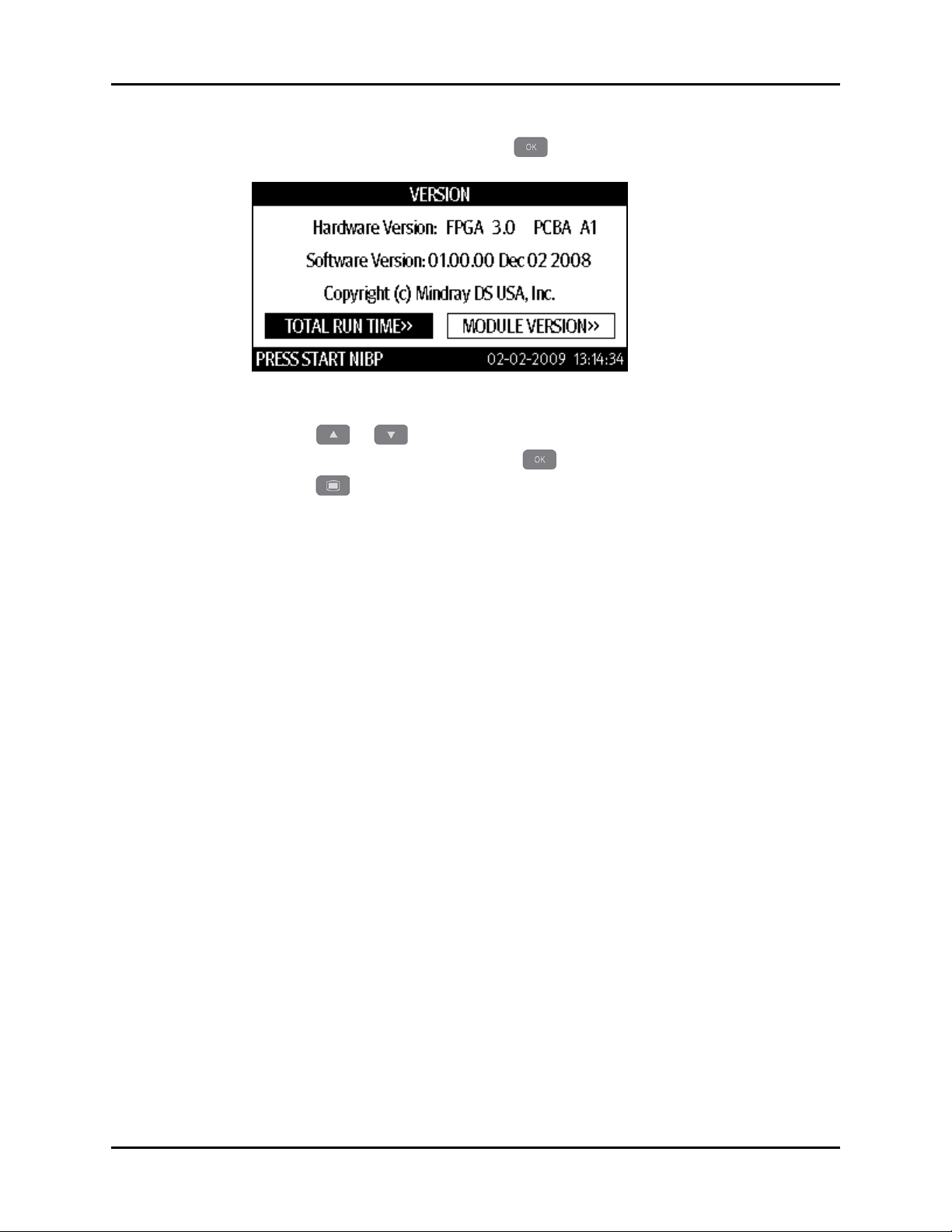
Troubleshooting Tech ni ca l Al ar m Ch ec k
5. Once VERSION is highlighted, press to display the VERSION dialog as shown
in FIGURE 3-3.
FIGURE 3-3 Example VERSION dialog
6. Press or to highlight TOTAL RUN TIME or MODULE VERSION.
7. Once the selection is highlighted, press to display the data.
8. Press to exit to the MAINTENANCE dialog.
3.4 Technical Alarm Check
If a technical alarm message displays on the LCD, eliminate the technical alarm first, then
troubleshoot according to the following instructions. For additional information on technical
alarm messages, possible causes, and corrective actions, refer to the Accutorr V Operating
Instructions.
Accutorr V Service Manual 0070-10-0702 3 - 3

Troubleshooting Guide Troubleshooting
3.5 Troubleshooting Guide
3.5.1 Power On/Off Failures
SYMPTOMS POSSIBLE CAUSE CORRECTIVE ACTIONS
The monitor fails to
start. AC LED or
battery LED does not
light
AC mains not connected or
battery too low
Power supply protection Refer to Power Supply Failures.
Cables defective or poorly
connected
Power switch and LED board
defective
Power module defective Replace the power module.
Main board Defective Replace the main board.
Confirm that the AC mains is properly connected and that
the battery capacity is sufficient.
•Confirm that the cables from the power switch and the
LED board to the keyboard, keyboard to the main
board, and the power module to the main board are
correctly connected.
•Confirm that the cables and connectors are not
damaged.
Replace the power switch and LED board.
3.5.2 Display Failure
SYMPTOMS POSSIBLE CAUSE CORRECTIVE ACTIONS
The display is black or
blank, but the monitor
still works correctly.
Images overlapped or
distorted
Cables defective or poorly
connected
Backlight defective Replace the LCD.
LCD defective Replace the LCD.
FPGA error Update or upgrade FPGA.
Cables defective or poorly
connected
•Confirm that the cables from the display to the main
board are correctly connected.
•Confirm that the cables and connectors are not
damaged.
•Confirm that the cable from the display to the main
board is correctly connected.
•Confirm that the cables and connectors are not
damaged.
3.5.3 LED Digital Display and Indication Lamp Failure
SYMPTOMS POSSIBLE CAUSE CORRECTIVE ACTIONS
LED digital display or
indication lamp
display abnormally.
Signal wires damaged • Confirm that the LED signal wires are correctly
LED digital display or
indication lamp damaged
connected.
•Confirm that the cables and connectors are not
damaged.
Replace the LED digital display or indication lamp.
3 - 4 0070-10-0702 Accutorr V Service Manual

Troubleshooting Troubleshooting Guide
3.5.4 Alarm Problems
SYMPTOMS POSSIBLE CAUSE CORRECTIVE ACTIONS
The alarm lamp does
not light or is
extinguished, but alarm
sounds
Alarm does not sound,
but alarm lamp lights
properly
Cables defective or
poorly connected
Key and display board
failure
Main board failure Replace the main board.
Audio alarm disabled
Cable defective or
poorly connected
Audio program error
identified in the system
program
Speaker failure Replace the speaker.
Main board failure Replace the main board,
•Confirm that the cables from alarm LED board to keyboard
and keyboard to main board are properly connected.
•Confirm that the connecting cables and connectors are not
damaged.
Replace the key and display board.
1. Press to display the SYSTEM SETUP dialog as shown
in FIGURE 3-1.
2. Press or to highlight MAINTENANCE.
3. Once MAINTENANCE is highlighted, press to
display the MAINTENANCE dialog as shown in FIGURE 3-2.
4. Press or to select USER MAINTENANCE.
5. Once USER MAINTENANCE is highlighted, press to
display the USER MAINTENANCE dialog.
6. Enter the required password.
7. In the pop-up menu, set the [MIN ALARM VOL] to a value
other than zero.
•Confirm that the cable between speaker and main board is
properly connected.
•Confirm that the connecting cables and connectors are not
damaged.
Upgrade system programs.
3.5.5 Key Failure
SYMPTOMS POSSIBLE CAUSE CORRECTIVE ACTIONS
Keys do not work Cables defective or
poorly connected
Keyboard failure Replace keyboard.
Accutorr V Service Manual 0070-10-0702 3 - 5
•Confirm that the cable between keyboard and main board
is properly connected.
•Confirm that the connecting cables and connectors are not
damaged.

Troubleshooting Guide Troubleshooting
3.5.6 Recorder Failures
SYMPTOMS POSSIBLE CAUSE CORRECTIVE ACTION
No printout Recorder module
disabled
Paper reversely installedRe-install the paper roll.
Cable defective or
poorly connected
Recorder power supply
failure
Recorder failure Replace the recorder.
Poor print quality or
paper not feeding
properly
Paper roll not properly
installed
Dirty thermal print head • Confirm that the thermal print head and the paper roller do
Recorder failure Replace the recorder.
•Confirm that the recorder status LED is on.
•If yes, reset the recorder. If no, check for other possible
causes.
•Confirm that the cable between recorder and main board is
appropriately connected.
•Confirm that the connecting cables and connectors are not
damaged.
Confirm that the power module outputs 5V DC and 16.8V DC
correctly.
Stop the recorder and re-install the paper roll.
not contain foreign matter.
•Clean the thermal print head with an appropriate detergent.
3.5.7 Interface Failures
SYMPTOMS POSSIBLE CAUSE CORRECTIVE ACTION
No nurse call signals are
issued
Bar code scanner unable
to be used
Incorrect function settings
Main board failure Replace the main board.
Bar code scanner failure Refer to Bar Code Scanner Failures.
Serial port failure Replace the main board.
1. Press to display the SYSTEM SETUP dialog as
shown in FIGURE 3-1.
2. Press or to highlight MAINTENANCE.
3. Once MAINTENANCE is highlighted, press to
display the MAINTENANCE dialog as shown in
FIGURE 3-2.
4. Press or to select NURSE CALL.
5. Once NURSE CALL is highlighted, press to
display the NURSE CALL dialog.
6. Select desired nurse call output.
3.5.8 Power Supply Failures
SYMPTOMS POSSIBLE CAUSE CORRECTIVE ACTION
Fluctuating battery voltage Battery failure Replace battery.
Cable defective or poorly
connected
Power board failure Replace the power board.
•Confirm that the cable between battery interface
board and power module is correctly connected.
•Confirm that the cables and connectors are not
damaged.
3 - 6 0070-10-0702 Accutorr V Service Manual

Troubleshooting Troubleshooting Guide
SYMPTOMS POSSIBLE CAUSE CORRECTIVE ACTION
Battery fails to be fully
charged
Battery unable to be
recharged
No +3.3 V output • Power supply protection
No +5.0 V output
No +12 V output
Battery failure Replace battery.
Cable defective or poorly
connected
Power board failure Replace the power board.
Battery damaged Replace battery and recharge the replacement battery.
Cable defective or poorly
connected
Power board failure Replace the power board.
•Power board failure
•Confirm that the cable between battery interface
board and the power module is properly
connected.
•Confirm that the connecting cables and connectors
are not damaged.
If the replacement battery can be recharged, the
original one fails.
•Confirm that the cable between battery interface
board and the power module is properly
connected.
•Confirm that the connecting cables and connectors
are not damaged.
•Turn off the monitor then restart it.
•If the problem remains, disconnect the AC mains
for 5 seconds and reconnect it, then restart the
monitor.
•If the problem still remains, replace power board.
NOTE: If the power module fails, it may damage other components
NOTE: If the parameter module, recorder, or bar code scanner
(e.g. the monitor suddenly shuts down during the start-up).
In this case, troubleshoot the power module using the
procedure described in the previous table.
malfunctions, check if the operating voltage is correct.
3.5.9 Network Related Problems
SYMPTOMS POSSIBLE CAUSE CORRECTIVE ACTIONS
The monitor can not
connect to the CMS.
Frequent dropouts and
network disconnections
No connection to LAN • Confirm that the cables and connectors are in good
condition and that the monitor is connected to the
network.
•Confirm that the hub and switch facilities are
correctly configured.
Improper LAN cable
connection
Incorrect IP address
configuration
Confirm that the LAN cable is connected. The LAN
cable must not be longer than 50 m.
Check for IP address conflict. Reconfigure IP address.
Accutorr V Service Manual 0070-10-0702 3 - 7

Troubleshooting Guide Troubleshooting
3.5.10 Software Upgrade Problems
SYMPTOMS POSSIBLE CAUSE CORRECTIVE ACTIONS
Bootstrap upgrade fails Power failure or unintended
power off during bootstrap
upgrade
Program upgrade fails Incorrect network connection • Confirm that the monitor is connected to the
Wrong upgrade package has
been downloaded
Incorrect IP address
configuration
Return the main board to the factory for repair.
network.
•Confirm that the hub or the switcher is functioning.
•Confirm that the net cables are of the right type and
have been connected correctly.
Incorrect upgrade package .mup files were used. Select
package according to the program to upgrade.
Configure a fixed IP address in range as specified for
the monitor. Do not upgrade a program while the
monitor is connected to a network.
3.5.11 Bar Code Scanner Failures
SYMPTOMS POSSIBLE CAUSE CORRECTIVE ACTIONS
Bar code scanner does
not work
Bar code scanner cannot
decode the target bar
codes
Scanned characters
incorrectly displayed on
the monitor
Bar code scanner not
powered on
Incorrect interface cables
used
Loose Interface cables Confirm that the interface cables are attached securely.
Bar code scanner not
programmed correctly.
Unreadable bar code Check if bar codes of the same type can be decoded.
Scanner and bar code at
improper distance and
angle
The monitor’s bar code
recognition configuration
does not meet the format of
the target bar code.
Scanner serial port output
incorrectly set
1. Press to display the SYSTEM SETUP dialog as
shown in FIGURE 3-1.
2. Press or to highlight MAINTENANCE.
3. Once MAINTENANCE is highlighted, press to
display the MAINTENANCE dialog as shown in
FIGURE 3-2.
4. Press or to select USER MAINTENANCE.
5. Once USER MAINTENANCE is highlighted, press
to display the USER MAINTENANCE dialog.
6. Enter the required password.
7. Set [BARCODE POWER] to [ON] in the menu to switch
on the bar code scanner.
Replace interface cables.
Re-program the bar code scanner to decode the specified bar
codes.
Aim the scanner at the bar code and adjust the distance
between the scanner and the bar code.
Download the correct bar code recognition configuration for
the monitor.
Configure the scanner’s serial port output according to the
host serial port settings.
3 - 8 0070-10-0702 Accutorr V Service Manual

Troubleshooting Troubleshooting Guide
3.5.12 NIBP Measurement Failures
SYMPTOMS POSSIBLE CAUSE CORRECTIVE ACTIONS
Unable to start NIBP
measurement
Cuff inflation/deflation
failure
Cables detective Confirm that the cables between NIBP module and the
main board are in good condition.
Main board failure Replace the main board.
Pump or valve damaged Replace the NIBP module.
Air tubing occluded Replace the air tubing.
3.5.13 SpO
SYMPTOMS POSSIBLE CAUSE CORRECTIVE ACTIONS
Unable to measure SpO
Measurement Failure
2
SpO2 sensor failure Replace the SpO2 sensor.
2
Cables defective Confirm that the cable between the SpO2 module and
SpO
module failure Replace the SpO2 module.
2
Main board failure Replace the main board.
the main board is in good condition.
3.5.14 Temperature Measurement Failures
SYMPTOMS POSSIBLE CAUSE CORRECTIVE ACTIONS
Unable to measure patient
temperature
Temp er at ur e pro be d am ag ed R ep la ce t he Te mp er at ur e pr ob e.
Cables detective Confirm that the cable between the Temperature
module and the main board is in good condition.
Main board failure Replace the main board.
Accutorr V Service Manual 0070-10-0702 3 - 9

Troubleshooting Guide Troubleshooting
This page intentionally left blank.
3 - 10 0070-10-0702 Accutorr V Service Manual

4.0
Repair and Disassembly
Too ls . .. .. .. .. .. .. .. .. .. .. .. .. .. .... .. .. .. .. .. .. .. .. .. .. .. .. .... .. .. .. .. .. .. .. .. .. .. .. .. .. .. .. .. .. .... .. .. .. .. .. .. 4- 2
Preparation for Disassembly............................................................................. 4-2
Disassembly................................................................................................... 4-3
Separating the Front and Rear Halves of the Monitor ......................................... 4-3
Disassembling the Front Housing Assembly ....................................................... 4-6
Removing the Main Rack Assembly................................................................... 4-8
Removing NIBP Module .................................................................................. 4-11
Removing the Main (CPU) Board ..................................................................... 4-13
Removing the Power Board.............................................................................. 4-13
Removing the Battery Connector Assembly......................................................... 4-13
Removing the Fan and Speaker ........................................................................ 4-14
Removing the Power Socket ............................................................................ 4-15
Disassembling the Temperature Module ............................................................. 4-16
Disassembling SpO2 Modules ......................................................................... 4-17
Disassembling the NIBP Module ....................................................................... 4-19
Accutorr V Service Manual 0070-10-0702 4 - 1

Tool s Repair and Disassembly
4.1 Tools
During disassembly and replacement, the following tools may be required:
•Phillips screwdrivers
•Wire cutters
•Sharp nose pliers
•Metric wrenches
•Metric nut drivers
4.2 Preparation for Disassembly
Before disassembling the monitor: stop monitoring patients, turn off the monitor, disconnect
all the accessories and peripheral devices, remove the battery, and disconnect the monitor
from the mains power supply.
CAUTION: Before disassembling the monitor, eliminate static charges.
CAUTION: Properly connect the cables or wires when reassembling the
When disassembling the parts labeled with static-sensitive
symbols, wear electrostatic discharge protection such as
antistatic wristband or gloves. Follow the correct sequence
to disassemble the monitor. Otherwise, the monitor may be
damaged permanently. Disconnect all the cables before
disassembling any parts. Take care not to damage any
cables or connectors.
monitor to avoid short circuits. When assembling the
monitor, select proper screws. If the wrong size screw is
tightened by force, the monitor may be damaged and the
screw or the part may not function as expected.
4 - 2 0070-10-0702 Accutorr V Service Manual

Repair and Disassembly Disassembly
M3x6 cross-head screw
M3x6 cross-head screw
Tem p cab l e con necto r
4.3 Disassembly
4.3.1 Separating the Front and Rear Halves of the Monitor
1. If the monitor is not configured with an Optional Temperature module, proceed to
step 2. If the monitor is configured with an Optional Temperature module:
a. Remove the two (2) M3×6 cross-head screws (as shown in Figure 4-1).
FIGURE 4-1 Remove two (2) M3x6 cross-head screws.
b. Disconnect the Temp cable connector from the PCBA as shown in Figure 4-2.
FIGURE 4-2 Disconnect the Temp cable connector.
Accutorr V Service Manual 0070-10-0702 4 - 3

Disassembly Repair and Disassembly
M3x8 cross-head screw
M3x8 cross-head screw
M3x8 cross-head screw
M3x8 cross-head screw
Clips
2. Remove the four (4) M3×8 cross-head screws (as shown in Figure 4-3).
FIGURE 4-3 Remove four (4) M3x8 cross-head screws.
3. Release the clips (as shown in Figure 4-4) on the front and rear housings.
FIGURE 4-4 Release the clips.
4 - 4 0070-10-0702 Accutorr V Service Manual

Repair and Disassembly Disassembly
Cable Connector
Cable Connector
Cable Connector
Tub i ng C o nnec t ion
Cable Connector
4. Disconnect the cables and air tubing connecting the front and the rear housings.
5. Separate the front and the rear housings (Figure 4-5).
FIGURE 4-5 Separate the front and rear housings.
NOTE: Exercise care when separating the front and the rear
Accutorr V Service Manual 0070-10-0702 4 - 5
housings. Be sure not to damage the cables and connectors.

Disassembly Repair and Disassembly
M3x6 cross-head screw
M3x6 cross-head screw
M3x6 cross-head screw
M3x6 cross-head screw
M3x6 cross-head screw
M3x6 cross-head screw
M3x8 cross-head screw
M3x8 cross-head screw
M3x8 cross-head screw
M3x8 cross-head screw
4.3.2 Disassembling the Front Housing Assembly
1. Remove the six (6) M3×6 cross-head screws (as shown in Figure 4-6), and remove the
key board.
FIGURE 4-6 Remove six (6) M3x6 cross-head screws.
2. Remove the four (4) M3×8 cross-head screws (as shown in Figure 4-7).
FIGURE 4-7 Remove four (4) M3x8 cross-head screws.
3. Disconnect the flexible cables on the button board.
4. Remove the LCD.
4 - 6 0070-10-0702 Accutorr V Service Manual

Repair and Disassembly Disassembly
M3x6 cross-head screw
M3x6 cross-head screw
Nellcor SpO2
Module
Masimo SpO2
Module
Screw
DMP SpO
2
Module
Screw
Screw
5. Remove the two (2) M3×6 cross-head screws (as shown in FIGURE 4-8), and take out
the SpO2 rack.
FIGURE 4-8 Remove two (2) M3x6 cross-head screws.
6. Remove the screw (as shown in FIGURE 4-9) to remove the SpO
rack.
FIGURE 4-9 Remove the screw.
module from the SpO2
2
Accutorr V Service Manual 0070-10-0702 4 - 7

Disassembly Repair and Disassembly
Screw
Screw
Plastic Nut
M3x6 cross-head screw
M3x6 cross-head screw
Clip
Clip
7. Remove the two (2) screws for the SpO2 signal cable (as shown in Figure 4-10).
8. Ta ke o ut t he S pO
signal cable.
2
FIGURE 4-10 Remove two (2) screws.
9. For DPM SpO
only, unscrew the plastic nut for the DPM SpO2 signal cable (as shown in
2
Figure 4-11).
FIGURE 4-11 For DPM SpO
only, unscrew the plastic nut.
2
4.3.3 Removing the Main Rack Assembly
1. Remove the two (2) M3×6 cross-head screws (as shown in Figure 4-12).
2. Ta ke o ut t he r ec or de r by p us hi ng t he c li ps i nw ar d.
FIGURE 4-12 Remove two (2) M3x6 cross-head screws.
4 - 8 0070-10-0702 Accutorr V Service Manual
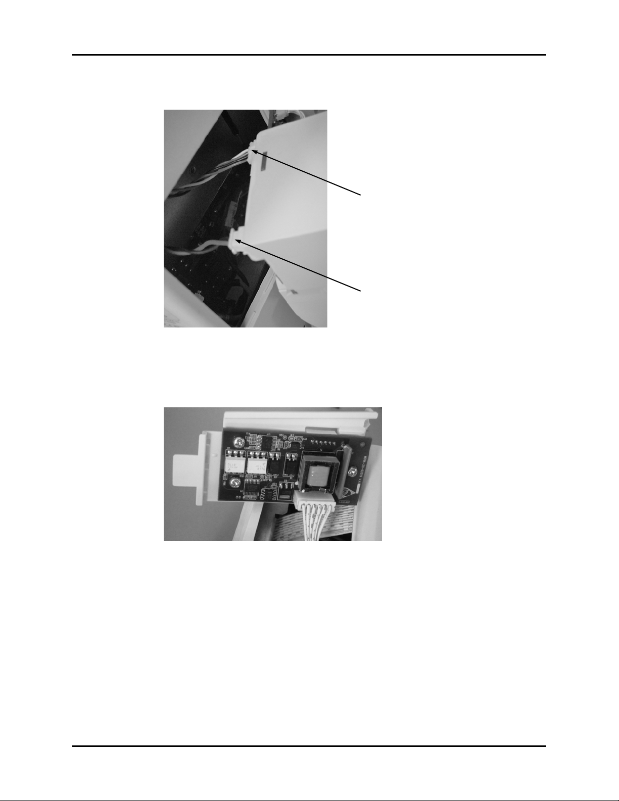
Repair and Disassembly Disassembly
Cable Connector
Cable Connector
3. Unplug the two (2) cable connectors (as shown in Figure 4-13) from the recorder.
FIGURE 4-13 Unplug two (2) cable connectors.
4. If the device is not configured with an optional Temperature module, skip to Step 6.
5. If the device is configured with an optional Temperature module, remove the
Temperature module board.
FIGURE 4-14 Remove optional temperature module board.
Accutorr V Service Manual 0070-10-0702 4 - 9

Disassembly Repair and Disassembly
M3x6 cross-head screw
M3x6 cross-head screw
M3x6 cross-head screw
M3x6 cross-head screw
M3x6 cross-head screw
M3x6 cross-head screw
6. Remove the six (6) M3×6 cross-head screws (as shown in Figure 4-15).
7. Ta ke o ut t he m ai n ra ck a ss em bl y.
FIGURE 4-15 Remove six (6) M3x6 cross-head screws.
4 - 10 0070-10-0702 Accutorr V Service Manual

Repair and Disassembly Disassembly
Unplug the NIBP module
M3x6 cross-head screw
M3x6 cross-head screw
M3x6 cross-head screw
4.3.4 Removing NIBP Module
1. Unplug the NIBP module from the CPU Board (as shown in Figure 4-16).
FIGURE 4-16 Unplug the NIBP module.
2. Remove the three (3) M3×6 cross-head screws (as shown in Figure 4-17).
3. Ta ke o ut t he N IB P ra ck .
FIGURE 4-17 Remove three (3) M3x6 cross-head screws.
Accutorr V Service Manual 0070-10-0702 4 - 11

Disassembly Repair and Disassembly
Cable Tie
Cable Connector
Speaker Cable
Recorder Cable
M3x6 cross-head screw
M3x6 cross-head screw
M3x6 cross-head screw
M3x6 cross-head screw
4.3.5 Removing the Main (CPU) Board
1. Unplug the Main board power cable from the power supply as shown in FIGURE 4-18.
2. Cut the tie wrap to the speaker as shown in FIGURE 4-18.
FIGURE 4-18 Unplug the Main board cable connector and cut one (1) tie wrap.
3. Unplug the speaker cable (J10) from the Main board (see FIGURE 4-19).
4. Unplug the recorder cable (J8) from the Main board (see FIGURE 4-19).
5. Ta ke ou t t he ma in bo ar d b y r em ov in g t he fo ur (4) M3×6 cross-head screws (as shown in
FIGURE 4-19).
FIGURE 4-19 Unplug (2) two cable connectors and remove four (4) M3x6 cross-head
screws.
4 - 12 0070-10-0702 Accutorr V Service Manual

Repair and Disassembly Disassembly
M3x6 cross-head screw
M3x6 cross-head screw
M3x6 cross-head screw
M3x6 cross-head screw
M3x6 cross-head screw
M3x6 cross-head screw
4.3.6 Removing the Power Board
1. Unplug the battery connector cable.
2. Remove the power board by removing the three (3) M3×6 cross-head screws (as shown
in Figure 4-20).
3. Unplug the remaining cable connectors (fan, AC mains connector, and Main (CPU)
board) from the Power board.
FIGURE 4-20 Remove three (3) M3x6 cross-head screws.
4.3.7 Removing the Battery Connector Assembly
Remove the three (3) M3×6 cross-head screws (as shown in Figure 4-21).
FIGURE 4-21 Remove three (3) M3x6 cross-head screws.
Accutorr V Service Manual 0070-10-0702 4 - 13

Disassembly Repair and Disassembly
Fan Cushion
M3x25 cross-head screw
M3x25 cross-head screw
M3x25 cross-head screw
4.3.8 Removing the Fan and Speaker
1. Cut the cable ties on the fan, speaker, and the main rack.
2. Remove the fan cushion (as shown in Figure 4-22).
FIGURE 4-22 Remove the Fan Cushion.
3. Remove the three (3) M3×25 cross-head screws (as shown in Figure 4-23).
4. Remove the fan.
5. Remove the speaker from the main rack.
FIGURE 4-23 Remove Three (3) M3x25 cross-head screws.
4 - 14 0070-10-0702 Accutorr V Service Manual

Repair and Disassembly Disassembly
Retaining Nut
M3x8 cross-head screw
M3x8 cross-head screw
4.3.9 Removing the Power Socket
1. Remove the retaining nut securing the grounding post (as shown in Figure 4-24).
2. Remove the grounding terminal.
FIGURE 4-24 Remove the retaining nut.
3. Remove the two (2) M3×8 cross-head screws (as shown in Figure 4-25).
4. Remove the power socket.
FIGURE 4-25 Remove Two (2) M3x8 cross-head screws.
Accutorr V Service Manual 0070-10-0702 4 - 15

Disassembly Repair and Disassembly
M3x6 cross-head screw
M3x6 cross-head screw
M3x6 cross-head screw
M3x6 cross-head screw
M3x6 cross-head screw
4.3.10 Disassembling the Temperature Module
1. Remove the two (2) M3×6 cross-head screws (as shown in Figure 4-26).
2. Ta ke t he c ov er p la te o ff .
FIGURE 4-26 Remove Two (2) M3x6 cross-head screws
3. Remove the three (3) M3×6 cross-head screws (as shown in Figure 4-27).
4. Remove the Temperature module board.
5. Remove the mylar sleeve.
FIGURE 4-27 Remove three (3) M3x6 cross-head screws.
4 - 16 0070-10-0702 Accutorr V Service Manual
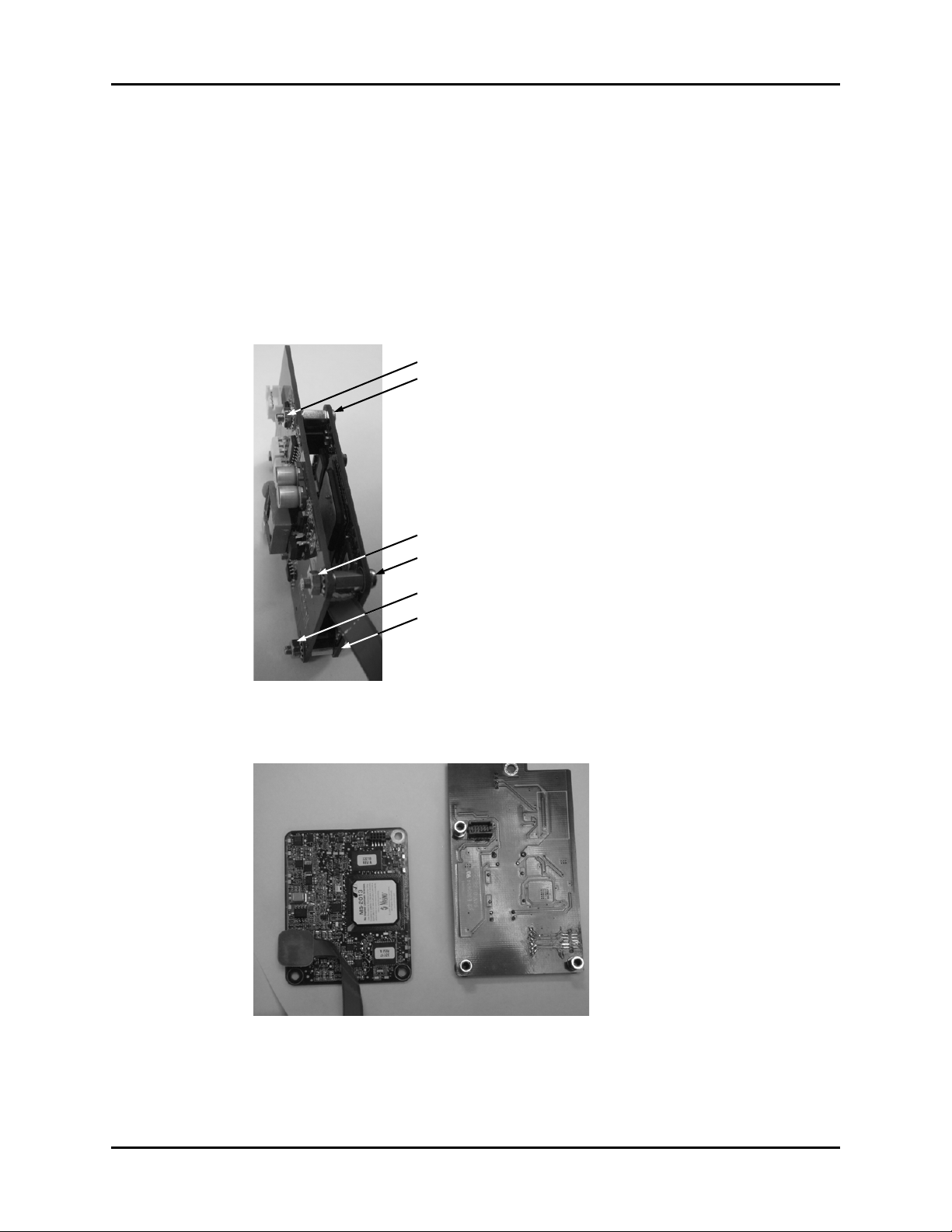
Repair and Disassembly Disassembly
M3x6 cross-head screw
M3x6 cross-head screw
M3x6 cross-head screw
M3 Nut
M3 Nut
M3 Nut
4.3.11 Disassembling SpO2 Modules
4.3.11.1 Disassembling a DPM SpO
The DPM SpO2 module consists of a single board requiring no disassembly.
module
2
4.3.11.2 Disassembling a Masimo SpO2 module
1. Remove the isolation power board by removing the three (3) M3 nuts (as shown in
Figure 4-28).
2. Remove the three (3) M3×6 cross-head screws.
FIGURE 4-28 Remove three (3) M3 nuts, and three (3) M3x6 cross-head screws.
3. Remove the SpO
FIGURE 4-29 Masimo SpO
Accutorr V Service Manual 0070-10-0702 4 - 17
board.
2
board and isolated power supply.
2

Disassembly Repair and Disassembly
M3x6 cross-head screw
FIGURE 4-30 Masimo isolated power supply.
4.3.11.3 Disassembling a Nellcor SpO2 module
1. Remove the M3×6 cross-head screw (as shown in FIGURE 4-31) to separate the SpO2
module from its isolated power supply (as shown in FIGURE 4-32).
FIGURE 4-31 Remove one (1) M3x6 cross-head screw.
FIGURE 4-32 Nellcor SpO
4 - 18 0070-10-0702 Accutorr V Service Manual
board and isolated power supply.
2

Repair and Disassembly Disassembly
Tie Wraps
Pump Cable Connector
Pump Tubing
Screw
Screw
4.3.12 Disassembling the NIBP Module
4.3.12.1 Removing the NIBP Pump
1. Unplug the pump cable connector from the NIBP board.
2. Disconnect the tubing.
3. Cut the two tie wraps holding the NIBP pump as shown in FIGURE 4-33.
4. Remove the pump.
FIGURE 4-33 Cut two (2) tie wraps.
4.3.12.2 Removing the NIBP Dump Valve
1. Unplug the dump valve cable connector from the NIBP board.
2. Disconnect the tubing.
3. Remove the two (2) screws on the bottom of the NIBP rack as shown in FIGURE 4-34.
4. Remove the dump valve.
FIGURE 4-34 Remove two (2) screws.
Accutorr V Service Manual 0070-10-0702 4 - 19

Disassembly Repair and Disassembly
Screws
4.3.12.3 Removing the NIBP Bleed Valve
1. Unplug the bleed valve cable connector from the NIBP board.
2. Disconnect the tubing.
3. Remove the two (2) screws as shown in FIGURE 4-35.
4. Remove the bleed valve.
FIGURE 4-35 Remove two (2) screws.
4 - 20 0070-10-0702 Accutorr V Service Manual

5.0
Parts
Main Assembly .............................................................................................. 5-2
Front Assembly............................................................................................... 5-3
Rear Housing Assembly................................................................................... 5-7
Main Bracket Assembly ................................................................................... 5-8
NIBP Assembly (Pump M6Q-100003- - -)........................................................... 5-10
NIBP Assembly (Pump 082-000056-00) ............................................................ 5-13
Tem per at ur e Mo du le S ub as se mb ly . .. ... .. .. .. .. .. .. .. .. .. .. .. .. .... .. .. .. .. .. .. .. .. .. .. .. .. .. .. .. .. .. 5 -16
Tem per at ur e Po we r Mo du le S ub as se mb ly . .. .. .. .. .. .. .. .. .. .. .. .. .. .. .. .. .. .. .. .. ... .. .. .. .. .. .. .. 5 -1 8
Accutorr V Service Manual 0070-10-0702 5 - 1

5 - 2 0070-10-0702 Accutorr V Service Manual
3
4
1
2
5
6
7
8
9
10
ITEM PART NUMBER DESCRIPTION
1 801-6101-00003-00 Front Shell Assembly
2 M6G-020015- - - Hose Silicone,1.6mmODX0.8mmID 10m/per
3 M04-004012- - - Screw, Crosshead M3×6
4 6101-30-46616 Main Bracket Assembly
5 801-6101-00011-00 Recorder module package
6 M04-000605- - - Screw, Pan Head Phillips M3X8
7 6101-20-46742 Rear Overlay (6101)
8 9211-20-87369 AC Inlet Retainer Clip
9 801-6101-00010-00 Rear Housing Assembly
10 M04-002505- - - Screw M3×6
Main Assembly Parts
5.1 Main Assembly
FIGURE 5-1 Main Assembly

Accutorr V Service Manual 0070-10-0702 5 - 3
11
ITEM PART NUMBER DESCRIPTION
11 0010-20-12194 Machine Pneumatic Socket Subassembly
12 801-6101-00003-00 Front Bezel (6101)
13 6101-20-46722 Alarm Light Cover (6101)
14 6101-20-46723 Silicon Keypad (6101)
15 6101-20-46762 Key Pad Fixer 2
16 M04-051003- - - Screw, Pan Head Phillips PT2.0X6
17 M04-021000- - - Flat Washer
18 6101-20-46743 Key Pad Fixer (6101)
12
13
14
15
16
18
17
Parts Front Assembly
5.2 Front Assembly
FIGURE 5-2 Front Bezel Assembly

5 - 4 0070-10-0702 Accutorr V Service Manual
21
ITEM PART NUMBER DESCRIPTION
21 6101-20-46734 SpO
2
Mounting Bracket (6101)
22 6101-30-46622 Nellcor SpO
2
module package
23 0010-10-42656 Nellcor SpO
2
Board
24 801-6101-00017-00 Nellcor Power Isolation Board
25 0010-30-12435 Nellcor SpO2 Flex Cable
26 6101-20-46719-51 Nellcor SpO
2
Interface Bracket
27 6101-30-46621 Masimo SpO
2
Module Package
28 801-6101-00016-00 Masimo SpO
2
Board
27
21
28
29
30
31
32
25
24
23
22
26
21
ITEM PART NUMBER DESCRIPTION
29 801-6101-00015-00 Masimo Power Isolation Board PCBA
30 0010-30-12436 Masimo SpO2 Flex Cable
31 6101-20-46720-51 Masimo SpO
2
Interface Bracket
32 6101-30-46620 DPM SpO
2
Module Package
33 9006-30-33900 DPM SpO
2
Board
34 6006-21-39390 DPM SpO
2
Signal Cable
35 6101-20-46718-51 DPM SpO
2
Interface Bracket
36 6101-20-46733 DPM SpO
2
Interface Bracket Plate
33
34
35
36
Front Assembly Parts
FIGURE 5-3 SpO2 Assembly

Accutorr V Service Manual 0070-10-0702 5 - 5
37
ITEM PART NUMBER DESCRIPTION
3 M04-004012- - - Screw, Crosshead M3×6
37 M04-011002- - - Hex Locknut with Conical Washer M3
38 0000-10-10997 LCD Module FSTN 320x160 LED White Backlight
39 6101-30-46609 Display Keyboard PCBA
40 6101-20-46752 Ferrite Fixer Plate
41 6101-20-46763 Ferrite Fixer Plate Isolation Sheet
42 M04-004015- - - Screw, Pan Head Phillips with Washer M3X8
43 M04-021024- - - Large Washer
44 6006-20-39502 LCD Display Back Plate
38
3
39
40
41
42
43
44
Parts Front Assembly
FIGURE 5-4 Display/Keyboard Assembly
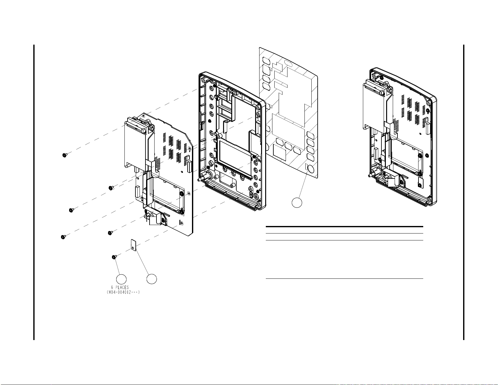
5 - 6 0070-10-0702 Accutorr V Service Manual
ITEM PART NUMBER DESCRIPTION
3 M04-004012- - - Screw Crosshead M3×6
45 6101-20-46732 Grounding Washer (6101)
46 047-002718-00
6101-20-46741-52
6101-20-46741-53
6101-20-46741-54
6101-20-46741-55
6101-20-46741-56
Front Overlay (6101), English
Front Overlay (6101), French
Front Overlay (6101), German
Front Overlay (6101), Spanish
Front Overlay (6101), Portuguese
Front Overlay (6101), Dutch
45
3
46
Front Assembly Parts
FIGURE 5-5 Front Shell Assembly

ITEM PART NUMBER DESCRIPTION
43 M04-021024- - - Large Washer
48 DA6H-20-22831 Foot Cushion
49 801-6101-00009-00 Battery Door (6101) and
Battery Door Link
51 M04-000802- - - Flat Washer
52 M04-003105- - - Tapping Screw PT3×8
53 6101-20-46751 Recorder Bracket (6101)
54 6006-20-39418 Speaker Spacer
55 6101-20-46713 Handle Cover (6101)
48
47
55
54
53
52
51
50
49
43
Accutorr V Service Manual 0070-10-0702 5 - 7
5.3 Rear Housing Assembly
Parts Rear Housing Assembly
FIGURE 5-6 Rear Housing Assembly

5 - 8 0070-10-0702 Accutorr V Service Manual
ITEM PART NUMBER DESCRIPTION
3 M04-004012- - - Screw, Crosshead M3×6
56 6101-20-46725 Main Bracket (6101)
57 6101-20-46736 Power Supply Board Isolation Sheet (6101)
58 6101-20-46735-51 I/O Overlay (6101)
59 6006-20-39451 Main Board Insulating Plate
60 0000-10-10996 Spring Strip
61 6101-20-46738 Battery Box Isolation Sheet (6101)
62 6101-20-46753 Battery Hook Torsion Spring
56
ITEM PART NUMBER DESCRIPTION
63 7000-20-24365 Torsion Spring
64 6006-20-39486 Battery Bar Setscrew
65 6101-20-46739 Fan Gasket (6101)
66 M04-051172- - - Screw, Flat Head Phillips M3X25
67 6101-20-46731 Fan Binder Plate (6101)
68 9201-20-53650 Fan (KDE1204PKV3)
69 6006-20-39379 Speaker Spacer
70 6006-20-39385 Speaker and Cables
71 6006-30-39449 Lithium Battery Assembly
72 2102-20-17166 Protective Ground Label
73 M04-004401- - - Hex Nut, M6
74 M04-004504- - - Spring Washer
75 M04-021003- - - Flat Washer
76 0509-20-00098 Grounding Terminal
77 M04-000405- - - Screw, Crosshead M3×8
78 6006-21-39386 Power Board AC Input cable
57
58
59
60
61
62
63
64
65
66
67
68
69
70
3
71
72
73
74
75
76
77
78
Main Bracket Assembly Parts
5.4 Main Bracket Assembly
FIGURE 5-7 Main Bracket Assembly

Accutorr V Service Manual 0070-10-0702 5 - 9
ITEM PART NUMBER DESCRIPTION
3 M04-004012- - - Screw, Crosshead M3×6
37 M04-011002- - - Nut, M3 with Spring Washer
79 6101-30-46601 AC-DC Power Supply PCBA
80 M04-000106- - - Bolt, M3×7
81 6101-20-46611 Keyboard Power Cable
79
ITEM PART NUMBER DESCRIPTION
82 6006-20-39492 Recorder Power Cable
83 6101-30-46618 NIBP Assembly
84 6006-20-39381 Recorder Signal Cable
85 6006-20-39380 Host Board Power Cable
86 6006-20-39384 LCD Signal Cable
87 M09A-20-62081 Communication Cable from Host Board to Isolation Board
88 6006-20-39382 SpO
2
Module Cable
89 6006-20-39383 Keyboard Signal Cable
90 M05-010R03- - - Button Battery Lithium 3V35mAh D12.5x2.0
91 801-6101-00001-00 Main Board
37
80
3
90
3
91
81
82
84
83
3
85
86
87
88
89
Parts Main Bracket Assembly
FIGURE 5-8 Main Bracket Assembly

5 - 10 0070-10-0702 Accutorr V Service Manual
NIBP Assembly (Pump M6Q-100003- - -) Parts
5.5 NIBP Assembly (Pump M6Q-100003- - -)
Accutorr V models with S/N A7503017K9 and higher are configured with the new NIBP pump (M6Q-100003- - -).
10
FIGURE 5-9 NIBP Assembly (Pump M6Q-100003- - -)
ITEM PART NUMBER DESCRIPTION
10 M04-002505- - - Screw, M3×6
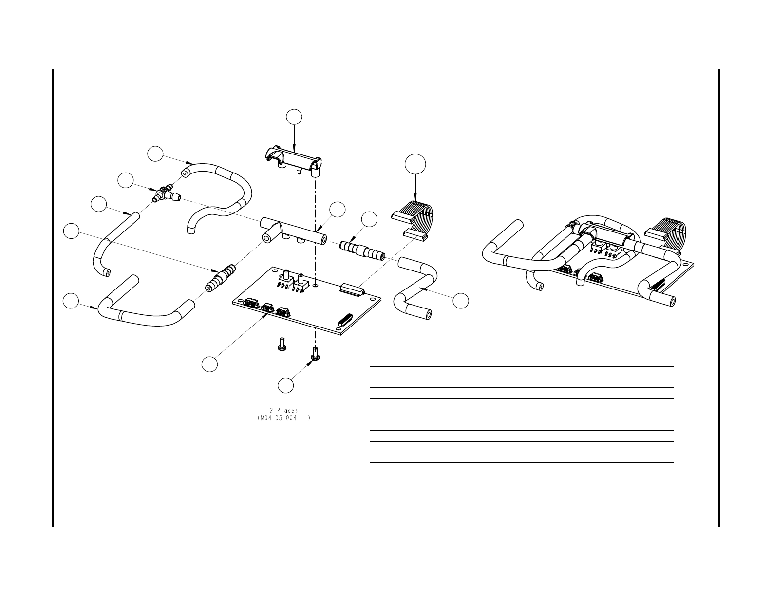
Accutorr V Service Manual 0070-10-0702 5 - 11
Parts NIBP Assembly (Pump M6Q-100003- - -)
98
95
94
96
97
96
93
92
100
99
95
94
ITEM PART NUMBER DESCRIPTION
92 M04-051004- - - Screw, PT2.6×6
93 051-000064-00 NIBP PCBA Module
94 A21-000002- - - Tubing, Silicone,1/8"X1/4" X100ft,2800546-100
95 S1-0378-02-0004 Filtered Orifice Restricto
96 S1-0008-10-0206 Tubing, Silicone,1/16"X3/16",TYGON 3350 (1foot)
97 3001-10-07066 T-Connector
98 6101-20-46756 NIBP Bracket Manifold
99 6101-20-46755 NIBP Manifold
100 6101-20-46610 Cable, Main Board to NIBP Module Board
FIGURE 5-10 NIBP Pneumatics (Pump M6Q-100003- - -)
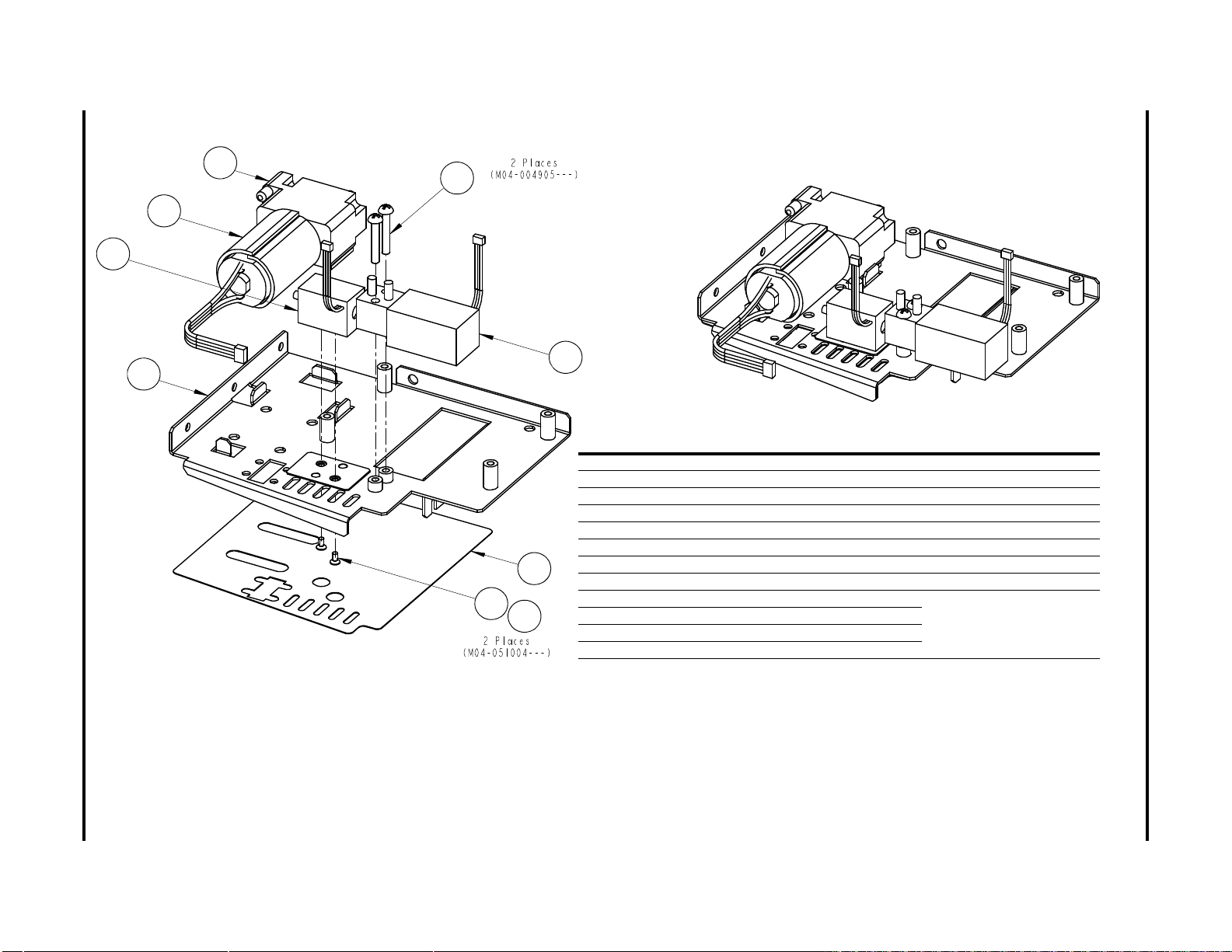
5 - 12 0070-10-0702 Accutorr V Service Manual
* Upgrading the old pump (082-000056-00) to the new rolling pump (M6Q-100003- - -) requires
FRU# 801-6101-00018-00 (pump kit), 047-001582-00 (label), and 042-001417-00 (bracket).
See section 5.6 (pg. 5-13) ‘‘NIBP Assembly (Pump 082-000056-00)’’ for the old pump assembly.
ITEM PART NUMBER DESCRIPTION
101 047-001582-00 * NIBP Bracket Label
102 M04-051137- - - Screw, M2×4
103 M90-000002-00 Insulation Washer F2
104 042-001417-00 * NIBP Bracket
107 082-000057-00 Valve Solenoid
108 M04-004905- - - Screw, M3×18
109 082-000058-00 Valve
105 M6Q-100003- - - Rolling Pump
* FRU# 801-6101-00018-00
contains these parts.
106 6101-20-46761 Pump Cushion
— 009-000588-00 Pump connection cable
— A90-000031- - - Cable Tie CHS-4x150mm
101
102
103
104
105
106
108
109
107
NIBP Assembly (Pump M6Q-100003- - -) Parts
FIGURE 5-11 NIBP Mechanical (Pump M6Q-100003- - -)

ITEM PART NUMBER DESCRIPTION
10 M04-002505- - - Screw, M3×6
10
Accutorr V Service Manual 0070-10-0702 5 - 13
Parts NIBP Assembly (Pump 082-000056-00)
5.6 NIBP Assembly (Pump 082-000056-00)
Accutorr V models with serial numbers lower than S/N A7503017K9 are configured with the old NIBP pump (083-000056-00).
FIGURE 5-12 NIBP Assembly (Pump 082-000056-00)

5 - 14 0070-10-0702 Accutorr V Service Manual
ITEM PART NUMBER DESCRIPTION
92 M04-051004- - - Screw, PT2.6×6
93 051-000064-00 NIBP PCBA Module
94 A21-000002- - - Tubing, Silicone,1/8"X1/4" X100ft,2800546-100
95 S1-0378-02-0004 Filtered Orifice Restricto
96 S1-0008-10-0206 Tubing, Silicone,1/16"X3/16",TYGON 3350 (1foot)
97 3001-10-07066 T-Connector
98 6101-20-46756 NIBP Bracket Manifold
99 6101-20-46755 NIBP Manifold
100 6101-20-46610 Cable, Main Board to NIBP Module Board
92
93
94
95
97
96
96
98
99
100
94
NIBP Assembly (Pump 082-000056-00) Parts
FIGURE 5-13 NIBP Pneumatics (Pump 082-000056-00)

Accutorr V Service Manual 0070-10-0702 5 - 15
* Upgrading the old pump (082-000056-00) to the new rolling pump (M6Q100003- - -) requires FRU# 801-6101-00018-00 (pump kit), 047-001582-00
(label), and 042-001417-00 (bracket). See section 5.5 (pg. 5-10) ‘‘NIBP
Assembly (Pump M6Q-100003- - -)’’ for the new rolling pump assembly.
ITEM PART NUMBER DESCRIPTION
101 6101-20-46737 NIBP Fram Overlay (6101)
102 M04-051137- - - Screw, M2×4
103 M90-000002-00 Insulation Washer F2
104 6101-20-46730 NIBP Bracket (6101)
105 082-000056-00 * Pump
106 6101-20-46761 Pump Cushion
107 082-000057-00 Valve Solenoid
108 M04-004905- - - Screw, M3×18
109 082-000058-00 Valve
101
102
103
104
105
106
107
108
109
Parts NIBP Assembly (Pump 082-000056-00)
FIGURE 5-14 NIBP Mechanical (Pump 082-000056-00)

5 - 16 0070-10-0702 Accutorr V Service Manual
ITEM PART NUMBER DESCRIPTION
10 M04-002505- - - Screw, M3×6
110 6101-20-46759 Temp Module Water Ingress Blocker
111 M09A-30-62103 Temp Measurement Board Subassembly
112 6101-20-46716 Temp Module Inner Cover
10
112
111
110
Temp er at ur e Mo du le S ub as se mbl y Parts
5.7 Temperature Module Subassembly
FIGURE 5-15 Temp er at ur e Mo du le S ub as se mb ly

Accutorr V Service Manual 0070-10-0702 5 - 17
ITEM PART NUMBER DESCRIPTION
113 6101-20-46717 Temp Probe Holder
114 6101-20-46715 Temp Module External Cover
115 6101-20-46724 Temperature Probe Holder Ring (6101)
116 M04-003905- - - Screw, Phillips PT3×6
116
115
114
113
Parts Te mp er at ur e Mo du le S ub as se mb ly
FIGURE 5-16 Tempe rat ure M odu le Sub ass emb ly

5 - 18 0070-10-0702 Accutorr V Service Manual
ITEM PART NUMBER DESCRIPTION
10 M04-002505- - - Screw, M3×6
117 M09A-20-62082 Communication Cable from Power Isolation Board to Temp Measurement Board
118 6101-20-46745 Rear Inner Cover Plate (6101)
119 M09A-30-62080 Temp Module Power Supply Board PCBA
10
119
117
118
Temp er at ur e Po we r M od ul e Su ba ss em bl y Parts
5.8 Temperature Power Module Subassembly
FIGURE 5-17 Tempe rat ure Po wer Mo dul e S uba sse mbl y

6.0
Test and Calibration
Introduction.................................................................................................... 6-2
Visual Test...................................................................................................... 6-4
Power-on Test ................................................................................................. 6-4
NIBP Calibration ............................................................................................ 6-4
NIBP Accuracy Test ......................................................................................... 6-8
SpO2 Test...................................................................................................... 6-12
Test in g th e Op ti on al Te mp er at ur e Mo du le .. .. .. .. .. .. .. .. .. .. .. .. .. .. .. .. .. .. .. .. .. .. .. .. ... .. .. .. . 6- 14
Nurse Call Performance Test ............................................................................ 6-16
Bar Code Scanner Test .................................................................................... 6-18
Electrical Safety Tests ...................................................................................... 6-20
Recorder Check.............................................................................................. 6-22
Software upgrade........................................................................................... 6-23
Accutorr V Service Manual 0070-10-0702 6 - 1

Introduction Te st a nd C al ib ra ti on
6.1 Introduction
To en su re t he m on it or a lw ay s fu nc ti on s pr op er ly, qualified personnel should perform regular
inspections, maintenance, and testing. This chapter provides the test procedures for the
monitor and includes recommended test equipment and frequency. Qualified personnel
should perform the testing and maintenance procedures as required and use appropriate test
equipment.
The testing procedures provided in this chapter are intended to verify that the monitor meets
the performance specifications. If the monitor or a module fails to perform as specified in any
test, repair or replacement is required to correct the problem. If the problem persists, contact
service.
CAUTION: All tests should be performed by qualified personnel only.
NOTE: Qualified personnel should acquaint themselves with the
test tools and confirm that test tools and cables are
applicable.
NOTE: When fields or buttons in a dialog have a line through them,
they are not available for selection or modification.
6 - 2 0070-10-0702 Accutorr V Service Manual

Test a nd C al ib ra ti on Introduction
6.1.1 Test Report
After completing the tests, service personnel should record test results in this table and retain
them for hospital records.
TES T EQUIPMEN T
Name Model/PN Next Calibration Due Date
TES T RECORD
No. Test Item Test Site Test Results
1
2
CONCLUSION
Pass/Fail: Tested by: Date:
6.1.2 Recommended Frequency
CHECK/MAINTENANCE ITEM FREQUENCY
Visual test When first installing or after reinstalling.
Power on test 1. When first installing or after reinstalling.
2. Following any maintenance or replacement of any main unit
parts.
NIBP tests Accuracy test 1. If the user suspects that the measurement is incorrect.
Leakage test
Calibration
test
SpO
2
Tem pe rat ur e te st
Bar code scanner test If the user suspects that bar code scan is incorrect.
Electrical safety tests Enclosure leakage
Recorder check Following any repair or replacement of the recorder.
current test
Earth leakage current
test
Patient leakage
current test
Patient auxiliary
current test
2. Following any repairs or replacement of the NIBP module.
3. At least once every two years.
1. Following any repair or replacement of the power module.
2. At least once every two years.
Accutorr V Service Manual 0070-10-0702 6 - 3

Visual Test Test a nd C al ib ra ti on
Accutorr V
Calibration
Ves sel
Reference
Manometer
Hose
6.2 Visual Test
Inspect the equipment for obvious signs of damage. Follow these guidelines when inspecting
the equipment:
•Carefully inspect the case, the display screen, and the buttons for physical damage.
•Inspect all external connections for loose connectors, bent pins, or frayed cables.
•Inspect all connectors on the equipment for loose connectors or bent pins.
•Make sure that the labels on the equipment are clearly legible.
6.3 Power-on Test
Verify t h a t the mo n itor ca n power u p correctly by following this procedure:
1. Insert the lithium battery in the battery compartment and connect the monitor to the AC
mains. The AC mains LED and battery LED light.
2. Press the Power On/Off button to turn on the monitor.
•The operating status LED built into the Power On/Off button illuminates.
• The system beeps to indicate it has passed the alarm sounds self test.
•All the LEDs on the front panel illuminate.
•The technical alarm lamp illuminates yellow, then red, and then turns off to indicate it
has passed the alarm lamp self test.
•The start-up screen clears, and the monitor enters the main screen, indicating start-up is
complete.
6.4 NIBP Calibration
Required Tools:
• One (1) T-Connector
•Three (3) pieces of Tubing
•One (1) Metal Vessel with volume of 500 ±25 ml
•One (1) Reference manometer with accuracy of 1 mmHg
To calibrate NIBP:
1. Attach the calibration vessel and reference manometer as shown in FIGURE 6-1.
FIGURE 6-1 NIBP calibration configuration
6 - 4 0070-10-0702 Accutorr V Service Manual
2. If needed, press (11) to display the Normal Screen.

Test a nd C al ib ra ti on NIBP Calibration
3. Press (12) to display the SYSTEM SETUP dialog.
4. Press (16) or (19) to highlight MAINTENANCE.
5. Once MAINTENANCE is highlighted, press (18) to display the
MAINTENANCE dialog as shown in FIGURE 6-2.
FIGURE 6-2 MAINTENANCE dialog
6. Press (16) or (19) to highlight NIBP TOOLS.
7. Once NIBP TOOLS is highlighted, press (18) to display the NIBP TOOLS
dialog.
8. Press (16) or (19) to highlight CALIBRATION, as shown in FIGURE 6-3.
FIGURE 6-3 NIBP TOOLS dialog
9. Once CALIBRATION is highlighted, press (18) to display the Enter Password
dialog, as shown in FIGURE 6-4.
FIGURE 6-4 ENTER PASSWORD dialog
Accutorr V Service Manual 0070-10-0702 6 - 5

NIBP Calibration Test a nd C al ib ra ti on
10. In the Enter Password dialog, press (18). See FIGURE 6-4.
11. Press (16) or (19) to set the first password digit to 3.
12. Press (18).
13. Press (16) or (19) to highlight the second password digit.
14. Press (18).
15. Press (16) or (19) to set the second password digit to 2.
16. Press (18).
17. Press (16) or (19) to highlight the third password digit.
18. Press (18).
19. Press (16) or (19) to set the third password digit to 1.
20. Press (18).
21. Press (16) or (19) to highlight OK.
22. Press (18).
NOTE: When the NIBP CALIBRATION dialog is first displayed,
INFLATE is highlighted, as shown in FIGURE 6-5.
FIGURE 6-5 NIBP CALIBRATION dialog with INFLATE highlighted
23. Press (18) to start pressurizing the calibration vessel.
NOTE: Use (16) or (19) to highlight CANCEL, then press
(18) to cancel the calibration.
NOTE: After the calibration vessel is pressurized, the reference
pressure field is highlighted, as shown in FIGURE 6-6.
FIGURE 6-6 NIBP CALIBRATION dialog with the reference pressure field highlighted
6 - 6 0070-10-0702 Accutorr V Service Manual
 Loading...