


BS-200
Chemistry Analyzer
Operation Manual

© 2006 Shenzhen Mindray Bio-medical Electronics Co., Ltd. All rights Reserved.
For this Operation Manual, the issued Date is 2006-03 (Version: 1.2).
Intellectual Property Statement
SHENZHEN MINDRAY BIO-MEDICAL ELECTRONICS CO., LTD. (hereinafter called
Mindray) owns the intellectual property rights to this Mindray product and this
manual. This manual may refer to information protected by copyrights or patents and
does not convey any license under the patent rights of Mindray, nor the rights of
others. Mindray does not assume any liability arising out of any infringements of
patents or other rights of third parties.
Mindray intends to maintain the contents of this manual as confidential information.
Disclosure of the information in this manual in any manner whatsoever without the
written permission of Mindray is strictly forbidden.
Release, amendment, reproduction, distribution, rent, adaption and translation of this
manual in any manner whatsoever without the written permission of Mindray is
strictly forbidden.
, , , , are the registered
trademarks or trademarks owned by Mindray in China and other countries. All
other trademarks that appear in this manual are used only for editorial purposes
without the intention of improperly using them. They are the property of their
respective owners.
Responsibility on the Manufacturer Party
Contents of this manual are subject to changes without prior notice.
All information contained in this manual is believed to be correct. Mindray shall not
be liable for errors contained herein nor for incidental or consequential damages in
connection with the furnishing, performance, or use of this manual.
Mindray is responsible for safety, reliability and performance of this product only in
the condition that:
all installation operations, expansions, changes, modifications and repairs of this
product are conducted by Mindray authorized personnel;
the electrical installation of the relevant room complies with the applicable
national and local requirements;
the product is used in accordance with the instructions for use.
WARNING:
It is important for the hospital or organization that employs this
equipment to carry out a reasonable service/maintenance plan.
Neglect of this may result in machine breakdown or injury of human
health.
i

Warranty
THIS WARRANTY IS EXCLUSIVE AND IS IN LIEU OF ALL OTHER WARRANTIES,
EXPRESSED OR IMPLIED, INCLUDING WARRANTIES OF MERCHANTABILITY
OR FITNESS FOR ANY PARTICULAR PURPOSE.
Exemptions
Mindray's obligation or liability under this warranty does not include any
transportation or other charges or liability for direct, indirect or consequential
damages or delay resulting from the improper use or application of the product or the
use of parts or accessories not approved by Mindray or repairs by people other than
Mindray authorized personnel.
This warranty shall not extend to:
any Mindray product which has been subjected to misuse, negligence or
accident;
any Mindray product from which Mindray's original serial number tag or product
identification markings have been altered or removed;
any product of any other manufacturer.
NOTE:
This equipment is to be operated only by medical professionals trained
and authorized by Mindray or Mindray-authorized distributors.
Return Policy
Return Procedure
In the event that it becomes necessary to return this product or part of this product to
Mindray, the following procedure should be followed:
1 Obtain return authorization: Contact the Mindray Service Department and
obtain a Customer Service Authorization (Mindray) number. The Mindray
number must appear on the outside of the shipping container. Returned
shipments will not be accepted if the Mindray number is not clearly visible.
Please provide the model number, serial number, and a brief description of
the reason for return.
2 Freight policy: The customer is responsible for freight charges when this
product is shipped to Mindray for service (this includes customs charges).
3 Return address: Please send the part(s) or equipment to the address offered
by Customer Service department
Company Contact
Manufacture: Shenzhen Mindray Bio-Medical Electronics Co., Ltd.
Address:
Mindray Building, Keji 12th Road South, Hi-tech Industrial Park,
Nanshan, Shenzhen, P.R.China, 518057
Phone:
Fax:
+86 755 26582479 26582888
+86 755 26582500 26582501
ii
Preface
Before using the BS-200 Chemistry Analyzer, please read this operation manual
thoroughly for relevant operation instructions.
Who Should Read This Manual
This manual is written for clinical laboratory professionals to
perform daily operating tasks;
perform system maintenance and troubleshooting;
learn about the BS-200 hardware and software.
WARNING:
The BS-200 Chemistry Analyzer is to be operated only by medical
professionals trained and authorized by Mindray or Mindray-authorized
distributors.
What Can You Find in This Manual
This operation manual covers principles, operations, daily maintenance and
troubleshooting of the system. Please operate and service the system strictly as
instructed by this manual.
Conventions Used in This Manual
This manual uses certain typographical conventions to clarify meanings in the text.
Bold font indicates a chapter title, such as 4 Maintenance
Bold and Italic font indicates text displayed on the screen, such as Sample Request.
Safety Symbols
This chart explains the symbols used in this manual.
When you see … Then …
WARNING:
Read the statement following the symbol. The
statement is alerting you to an operating hazard
that can cause personal injury.
BIOHAZARD:
Read the statement following the symbol. The
statement is alerting you to a potentially
biohazardous condition.
1
Preface
When you see … Then …
CAUTION:
Read the statement following the symbol. The
statement is alerting you to a possibility of
system damage or unreliable results.
Read the statement following the symbol. The
statement is alerting you to information that
requires your attention.
NOTE:
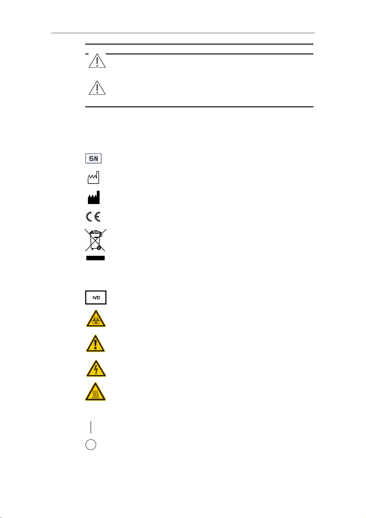
Labels Used on the System
The labels attached to the panels of the system use symbols with the text to clarify
the meaning of the text. The chart below explains the symbols on the labels.
Serial Number
Date of Manufacture
Manufacturer
The device is fully in conformance with the Council Directive
Concerning In Vitro Diagnostic Medical Devices 98/79/EC.
The following definition of the WEEE label applies to EU member
states only: The use of this symbol indicates that this product
should not be treated as household waste. By ensuring that this
product is disposed of correctly, you will help prevent bringing
potential negative consequences to the environment and human
health. For more detailed information with regard to returning and
recycling this product, please consult the distributor from whom
you purchased the product.
~
In Vitro Diagnostic equipment
Biohazard Warning: risk of potentially biohazardous infection
Warning: risk of personal injury or equipment damage
Warning: risk of electric shock
Warning: risk of burn
Alternating current (AC)
ON (MAIN POWER)
OFF (MAIN POWER)
2

Preface
ON (Power)
OFF (Power)
Graphics
All graphics, including screens and printout, are for illustration purpose only and
must not be used for any other purposes.
EC Representative
Name:
Address:
Phone:
Fax:
Shanghai International Holding Corp. GmbH (Europe)
Eiffestrasse 80 D-20537 Hamburg Germany
+49 40 2513174
+49 40 255726
3

Preface
Safety Precautions
Observe the following safety precautions when using the BS-200 Chemistry Analyzer.
Ignoring any of these safety precautions may lead to personal injury or equipment
damage.
WARNING:
If the system is used in a manner not specified by Mindray, the
protection provided by the system may be impaired.
Preventing Electric Shock
Please observe the following instructions to prevent electric shock.
WARNING:
When the MAIN POWER is on, users must not open the rear cover or
side cover.
Liquid ingression may lead to electric shock or equipment damage. In
case of liquid ingression, shut off the power supply and contact
Mindray Service Department or your local distributor.
Preventing Personal Injury Caused by Moving Parts
Please observe the following instructions to prevent personal injury caused by
moving parts.
WARNING:
Do not touch such moving parts as probe and mixing bar, when the
system is in operation.
Do not put your finger or hand into any open part when the system is
in operation.
Preventing Personal Injury Caused by Photometer Lamp
Please observe the following instructions to prevent personal injury caused by
photometer lamp.
WARNING:
Light sent by the photometer lamp may hurt your eyes. Do not stare
into the lamp when the system is in operation.
If you want to replace the photometer lamp, first switch off the MAIN
POWER and then wait at least 30 minutes for the lamp to cool down
before touching it. Do not touch the lamp before it cools down, or you
may get burned.
4
Preventing Infection
Please observe the following instructions to protect against the biohazardous
infection.
BIOHAZARD:
Inappropriately handling samples may lead to biohazardous infection.
Do not touch the sample, mixture or waste with your hands. Wear
gloves and lab coat and, if necessary, goggles.
In case your skin contacts the sample, follow standard laboratory
safety procedure and consult a doctor.
Certain reagents are strongly acid or alkaline. Exercise caution when
using the reagents. In case your skin or clothes contact the reagents,
wash them off with soap and clean water. In case the reagents spill
into your eyes, rinse them with much water and consult an oculist.
Treating Waste
Preface
Please observe the following instructions to prevent environmental pollution and
personal injury caused by waste.
BIOHAZARD:
Dispose of the waste in accordance with your local or national
guidelines for biohazard waste disposal and consult the manufacturer
or distributor of the reagents for details.
Preventing Fire or Explosion
Please observe the following instructions to prevent fire and explosion.
WARNING:
Do not use flammable substance around the system.
5
Preface
Precautions on Use
To use the BS-200 Chemistry Analyzer safely and efficiently, please pay attention to
the following operation notes.
Intended Use
WARNING:
The BS-200 Chemistry Analyzer is a chemistry system that is designed
for the in vitro quantitative determination of clinical chemistries in
serum, plasma, urine or CSF samples. Please consult Mindray first if
you want to use the system for other purposes.
To draw a clinical conclusion, please also refer to the patient’s clinical
symptoms and other test results.
Operator
WARNING:
The BS-200 Chemistry Analyzer is to be operated only by medical
professionals trained and authorized by Mindray or Mindray-authorized
distributors.
Environment
CAUTION:
Please install and operate the system in an environment specified by
this manual. Installing and operating the system in other environment
may lead to unreliable results and even equipment damage.
To relocate the system, please contact Mindray Service Department or
your local distributor.
Preventing Interference by Electromagnetic Noise
CAUTION:
Electromagnetic noise may interfere with operations of the system. Do
not install devices generating excessive electromagnetic noise around
the system. Do not use such devices as mobile phones or radio
transmitters in the room housing the system. Do not use other CRT
displays around the system.
Do not use other medical instruments around the system that may
generate electromagnetic noise to interfere with their operations.
6
Operating the System
CAUTION:
Operate the system strictly as instructed by this manual. Inappropriate
use of the system may lead to unreliable test results or even
equipment damage or personal injury.
Before using the system for the first time, run the calibration program
and QC program to make sure the analyzer is in proper state.
Be sure to run the QC program every time you use the system,
otherwise the result may be unreliable.
Do not open the cover of the sample/reagent disk when the system is
in operation.
The RS-232 port on the analyzing unit is to be used for connection with
the operation unit only. Do not use it for other connections. Only use
the supplied cable for the connection.
The operation unit is a personal computer with the control software
installed. Installing other software or hardware on this computer may
interfere with the system operation. Do not run other software when the
system is working.
Preface
Do not use this computer for other purposes. Inappropriate use of it will
probably introduce computer virus, which may spread into the system
through floppy disks, software or network.
Do not touch the display, mouse or keyboard with wet hands or hands
with chemicals.
Don’t place the MAIN POWER to ON again within 10 seconds since
placing it to OFF; otherwise the system may enter the protection
status. If it does so, place the MAIN POWER to OFF and place it to ON
again.
Maintaining the System
CAUTION:
Maintain the system strictly as instructed by this manual. Inappropriate
maintenance may lead to unreliable results or equipment damage or
personal injury.
To wipe off dust from the system surface, use a soft, clean and wet (not
too wet) cloth, soaked with soap water if necessary, to clean the
surface. Do not use such organic solvents as ethanol for cleaning. After
cleaning, wipe the surface dry with dry cloth.
Switch off all the powers and disconnect the power plug before
cleaning. Take necessary measures to prevent water ingression into
the system, otherwise it may lead to equipment damage or personal
injury.
Replacement of such major parts as photometer, probe, mixing bar and
syringe plunger assembly must be followed by a calibration.
7
Preface
Samples
CAUTION:
Use serum samples that are completely separated from blood clots or
urine samples that are free from suspended matter. If fibrin exists in the
serum samples or suspended matter exists in the urine samples, the
probe may be blocked.
Medicines, anticoagulants or preservative in the samples may lead to
unreliable results.
Hemolysis, jaundice or chylomicron in the samples may lead to
unreliable test results, so sample blanks are recommended.
Store the samples properly. Improper storage may change the
compositions of the samples and lead to unreliable results.
Sample volatilization may lead to unreliable results. Do not leave the
sample open for a long period.
Not all the tests the reagents claim capable of analyzing can be
analyzed on the system. Consult the reagent suppliers for details.
Certain samples need to be processed before being analyzed by the
system. Consult the reagent suppliers for details.
The system has a specific requirement on the sample volume. Refer to
this manual for proper sample volume.
Load the sample to proper tube position on the sample disk before the
analysis begins; otherwise you will not obtain correct results.
Reagents, Calibrators and Controls
CAUTION:
Use proper reagents, calibrators and controls in the system.
Select appropriate reagents according to performance characteristics
of the system. Consult the reagent suppliers, Mindray or
Mindray-authorized distributor for details, if you are not sure about your
reagent choice.
Store and use the reagents, calibrators and controls strictly as
instructed by the suppliers. Otherwise, you may not obtain reliable
results or best performance of the system.
Perform calibration after changing the reagents. Otherwise, you may
not obtain reliable results.
Contamination caused by carryover among reagents may lead to
unreliable test results. Consult the reagent suppliers for details.
8
Setting up the System
CAUTION:
To define such parameters as sample volume, reagent volume and
wavelength, follow the instructions in this manual and the instructions
of reagents.
Backing up Data
NOTE:
The system automatically stores the data to the built-in hard disk.
However, data loss is still possible due to mis-deletion or physical
damage of the hard disk. Mindray recommends you to regularly back
up the data to such medium as CDs.
Computer and Printer
Preface
NOTE:
Refer to their operation manuals for details.
External Equipment
WARNING:
External equipment connected to the system, such as PC and printer,
shall be consistent with IEC 60950 or EN 60950.
9


Contents
Preface.......................................................................................................................................... 1
Who Should Read This Manual ............................................................................................. 1
What Can You Find in This Manual........................................................................................ 1
Conventions Used in This Manual ......................................................................................... 1
Safety Precautions ................................................................................................................. 4
Precautions on Use................................................................................................................ 6
1 System Description ..........................................................................................................1-1
1.1 Hardware Introduction .........................................................................................1-1
1.1.1 Analyzing Unit ...................................................................................... 1-1
1.1.2 Operation Unit ...................................................................................... 1-6
1.1.3 Output Unit ...........................................................................................1-6
1.2 Software Introduction........................................................................................... 1-6
1.2.1 Software Interface ................................................................................1-6
1.2.2 Main Interface Components .................................................................1-8
2 Installation ......................................................................................................................... 2-1
2.1 Unpacking............................................................................................................ 2-1
2.2 Installation Requirements .................................................................................... 2-1
2.2.1 Installation Environment Requirements................................................2-1
2.2.2 Power Requirements............................................................................ 2-2
2.2.3 Temperature and Humidity Requirements............................................ 2-2
2.2.4 Water Supply and Drain Requirements................................................ 2-3
2.2.5 Space and Accessibility Requirements.................................................2-3
2.3 Connecting Deionized Water Tank ...................................................................... 2-4
2.4 Connecting Waste Tank....................................................................................... 2-5
2.5 Installing/Removing Sample/Reagent Disk ......................................................... 2-5
2.6 Installing/Removing Sample Tubes ..................................................................... 2-6
2.7 Installing/Removing Reagent Bottles...................................................................2-7
2.8 Installing/Removing Cuvettes .............................................................................. 2-7
3 Basic Operations .............................................................................................................. 3-1
3.1 Daily Procedure ................................................................................................... 3-1
3.2 Preparing for Analysis.......................................................................................... 3-2
3.2.1 Checking before Startup....................................................................... 3-2
3.2.2 Power-on .............................................................................................. 3-3
3.2.3 Starting the Control Software ............................................................... 3-3
3.2.4 Setting Up the Analyzer........................................................................ 3-4
3.2.5 Preparing Reagents..............................................................................3-5
3.3 Starting Analysis ..................................................................................................3-5
3.3.1 Reagent Blank...................................................................................... 3-5
3.3.2 Calibration ............................................................................................3-5
3.3.3 QC ........................................................................................................ 3-6
3.3.4 Samples................................................................................................ 3-6
3.4 Processing Results.............................................................................................. 3-7
3.4.1 Editing Results of Samples ..................................................................3-7
3.4.2 Printing Results of Samples ................................................................. 3-7
3.5 Finishing Analysis ................................................................................................3-7
3.5.1 Exiting the Control Software................................................................. 3-7
3.5.2 Shutdown..............................................................................................3-7
3.5.3 Operations after Shutdown................................................................... 3-8
I

Contents
4 Advanced Operations....................................................................................................... 4-1
4.1 Sample Request .................................................................................................. 4-1
4.1.1 Sample Information .............................................................................. 4-3
4.1.2 Delete a Sample................................................................................... 4-5
4.1.3 Change Position ................................................................................... 4-6
4.1.4 Requesting Samples or Modifying Information ....................................4-7
4.2 QC Request......................................................................................................... 4-7
4.3 Start ...................................................................................................................4-10
4.4 Probe Stop......................................................................................................... 4-11
4.5 Stop....................................................................................................................4-12
4.6 Current Results.................................................................................................. 4-13
4.7 Replace.............................................................................................................. 4-15
4.8 Re-log ................................................................................................................ 4-17
4.9 Exit..................................................................................................................... 4-17
4.10 History................................................................................................................ 4-18
4.10.1 Conditions........................................................................................... 4-20
4.10.2 Add Off-system Test Results .............................................................. 4-22
4.10.3 Compensate Results .......................................................................... 4-23
4.10.4 Edit Results ........................................................................................4-25
4.10.5 Reaction Curve................................................................................... 4-27
4.10.6 Delete Results .................................................................................... 4-28
4.10.7 Print Results ....................................................................................... 4-29
4.10.8 Result Trend Curve ............................................................................4-30
4.11 Reagent ............................................................................................................. 4-32
4.12 Calibration.......................................................................................................... 4-33
4.12.1 Calibration Request............................................................................ 4-33
4.12.2 Results................................................................................................ 4-37
4.12.3 Calibrator............................................................................................ 4-45
4.13 QC .....................................................................................................................4-47
4.13.1 Real-time QC...................................................................................... 4-48
4.13.2 Daily QC ............................................................................................. 4-49
4.13.3 Day to Day QC ...................................................................................4-52
4.13.4 Control................................................................................................ 4-55
4.14 Status................................................................................................................. 4-57
4.14.1 Sample Disk .......................................................................................4-58
4.14.2 Reagent Disk...................................................................................... 4-61
4.14.3 Reaction Disk .....................................................................................4-65
4.15 Statistics.............................................................................................................4-65
4.15.1 Worklist............................................................................................... 4-66
4.15.2 Results................................................................................................ 4-67
4.15.3 Workload ............................................................................................4-70
4.15.4 Charges .............................................................................................. 4-72
4.16 Setup .................................................................................................................4-74
4.16.1 Test ..................................................................................................... 4-75
4.16.2 Profile .................................................................................................4-85
4.16.3 Calculation.......................................................................................... 4-87
4.16.4 Off-system Test................................................................................... 4-89
4.16.5 Carryover............................................................................................ 4-90
4.16.6 System................................................................................................ 4-91
4.16.7 Hospital............................................................................................... 4-96
4.16.8 User .................................................................................................... 4-98
4.16.9 Print .................................................................................................. 4-101
4.17 Maintenance .................................................................................................... 4-105
4.17.1 Daily Maintenance............................................................................ 4-105
4.17.2 Log.................................................................................................... 4-107
4.17.3 Import/Export.................................................................................... 4-109
4.17.4 Commission...................................................................................... 4-111
5 Maintenance ...................................................................................................................... 5-1
II

Contents
5.1 Preparation .......................................................................................................... 5-1
5.2 Daily Maintenance ............................................................................................... 5-2
5.2.1 Checking Remaining Deionized Water.................................................5-2
5.2.2 Emptying Waste Tank........................................................................... 5-3
5.2.3 Checking Connection of Deionized Water............................................5-3
5.2.4 Checking Connection of Wastewater ................................................... 5-4
5.2.5 Checking Syringe ................................................................................. 5-5
5.2.6 Checking Probe.................................................................................... 5-6
5.2.7 Checking Mixing Bar ............................................................................5-7
5.3 Weekly Maintenance ........................................................................................... 5-7
5.3.1 Cleaning Probe..................................................................................... 5-7
5.3.2 Cleaning Mixing Bar ............................................................................. 5-8
5.3.3 Washing Deionized Water Tank ........................................................... 5-9
5.3.4 Washing Waste Tank.......................................................................... 5-10
5.3.5 Cleaning Sample/Reagent Compartment .......................................... 5-11
5.3.6 Cleaning Panel of Analyzing Unit....................................................... 5-11
5.4 Monthly Maintenance ........................................................................................5-12
5.4.1 Cleaning Wash Well of Probe.............................................................5-12
5.4.2 Cleaning Wash Well of Mixing Bar..................................................... 5-12
5.5 Maintenance Every Six Months .........................................................................5-12
5.6 Irregular Maintenance........................................................................................ 5-13
5.6.1 Unclogging Probe............................................................................... 5-13
5.6.2 Replacing Probe................................................................................. 5-16
5.6.3 Replacing Mixing Bar .........................................................................5-17
5.6.4 Replacing Plunger Assembly of Syringe ............................................ 5-18
5.6.5 Replacing Lamp .................................................................................5-20
5.7 Maintenance Log ...............................................................................................5-22
6 Troubleshooting................................................................................................................6-1
7 Calculation Methods......................................................................................................... 7-1
7.1 Analytical Methods ..............................................................................................7-1
7.1.1 Endpoint ...............................................................................................7-1
7.1.2 Fixed-Time............................................................................................7-2
7.1.3 Kinetic................................................................................................... 7-3
7.2 Calculation Process............................................................................................. 7-5
7.2.1 Absorbance ..........................................................................................7-5
7.2.2 Response .............................................................................................7-6
7.2.3 Calibration Parameters......................................................................... 7-9
7.2.4 Concentration ..................................................................................... 7-12
7.2.5 QC rules .............................................................................................7-14
Appendix A Specifications............................................................................................ A-1
A.1 Technical Specifications.......................................................................................A-1
A.2 Power Requirements ...........................................................................................A-1
A.3 Environmental Requirements ..............................................................................A-2
A.3.1 Storage Requirements..........................................................................A-2
A.3.2 Operation Requirements ......................................................................A-2
A.4 Dimension and Weight ........................................................................................A-2
A.5 Other Specifications.............................................................................................A-2
A.6 Input/Output Devices ...........................................................................................A-2
A.7 Interface...............................................................................................................A-3
Appendix B Supplies ..................................................................................................... B-1
Appendix C Index........................................................................................................... C-1
III

1 System Description
This chapter includes the following two sections:
Hardware Introduction
Software Introduction
The BS-200 Chemistry Analyzer is a chemistry system that is designed for the in
vitro quantitative determination of clinical chemistries in serum, plasma, urine or CSF
samples.
NOTE:
Not all the tests the reagents claim capable of analyzing can be
analyzed on the system. Consult the reagent suppliers for details.
1.1 Hardware Introduction
The system consists of the following three units – the analyzing unit, operation unit
and output unit.
1.1.1 Analyzing Unit
The analyzing unit consists of the following major parts:
Sample/Reagent Disk
Dispenser
Mixer
Reaction Disk
Photometric System
1-1
System Description
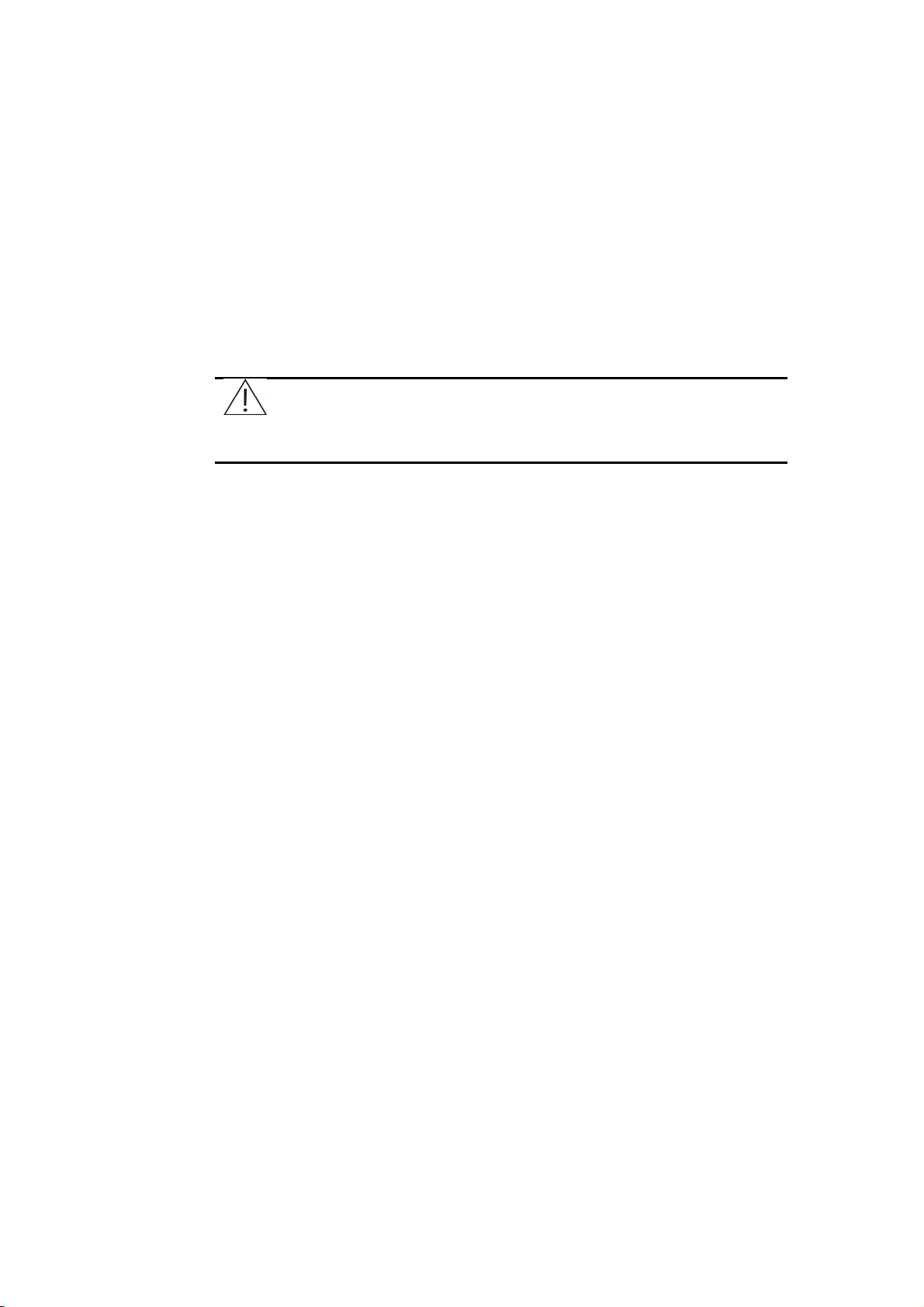
Figure 1-1 Analyzing unit
Cover
Syringe
Dispenser
Mixer
MAIN POWER
Power
1.1.1.1 Sample/Reagent Disk
The sample/reagent disk holds sample tubes and reagent bottles.
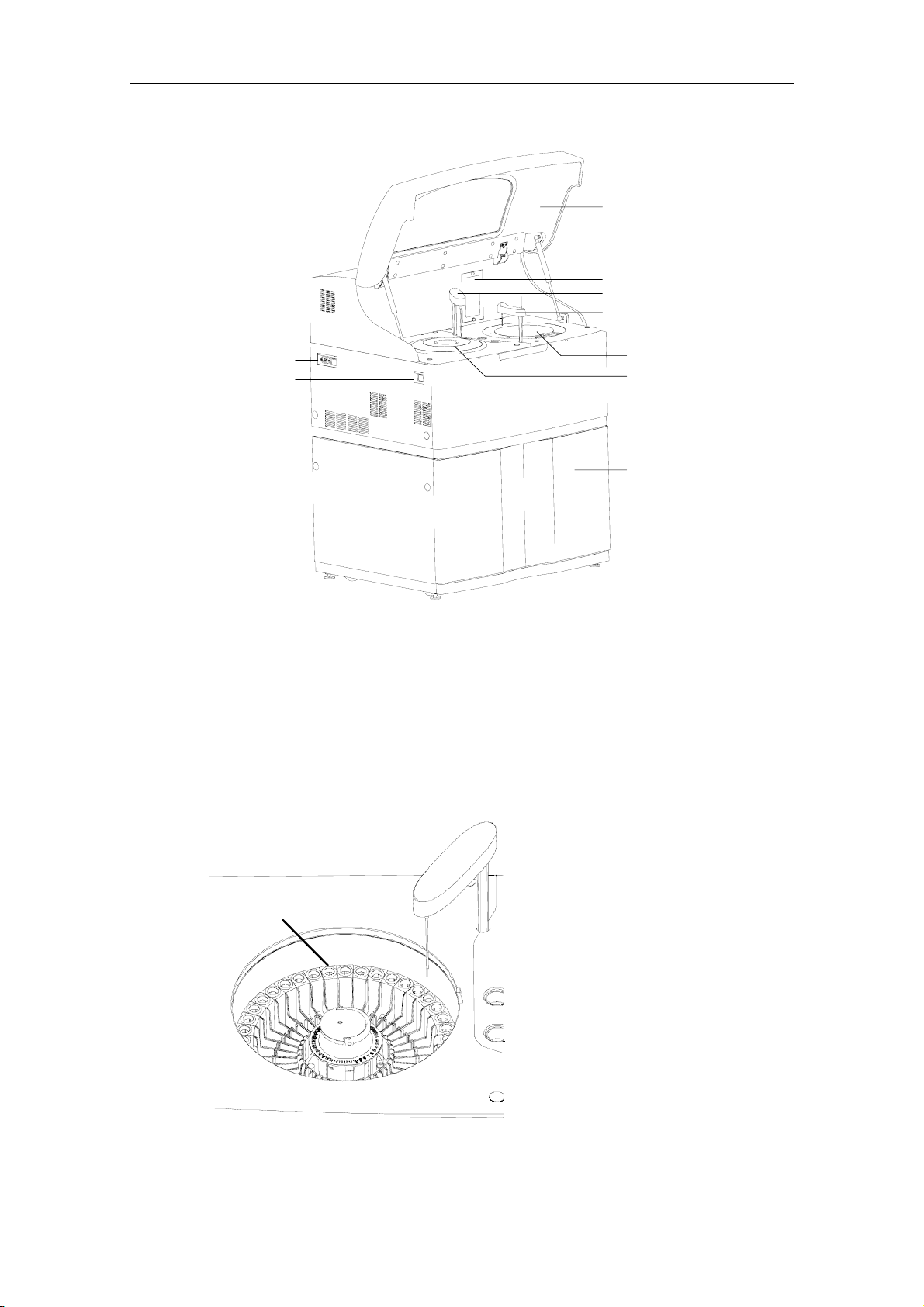
Figure 1-2 Sample/Reagent disk
Reaction Disk
Sample/Reagent Disk
Upper Cabinet
Lower Cabinet (optional)
Sample/reagent Disk
The disk is composed of two circles – sample disk on the outer circle and reagent
disk on the inner circle.
1-2
System Description
The sample disk provides 40 sample tube positions and the reagent disk provides 40
reagent bottle positions. On the reagent disk, No. 39 is for detergent and No. 40 is
for distilled water.
NOTE:
Mindray recommends you to use the following detergents:
Acid: 0.1mol/l hydrochloric acid; Alkaline: 0.5% (V/V) javel water。
The sample disk can hold the following sample tubes:
Micro sample cup and centrifugal tube
Collection tube: Ф12×68.5, Ф12×99, Ф12.7×75 and Ф12.7×100
Plastic tube
The reagent disk can only hold Mindray bottles, which are available in two types,
40ml and 20ml.
The sample/reagent disk is located in the sample/reagent compartment, which has a
refrigerator to keep the temperature at 4-15 ˚C.
1.1.1.2 Dispenser
The dispenser is composed of a probe, arm and rotor.
WARNING:
Make sure the disk cover is closed; otherwise it may degrade the
refrigeration and damage the probe.
Before running the analyzing unit, make sure that the disk cover is
closed and the round red mark on the cover is aligned with its
counterpart on the panel. Otherwise the probe may be damaged.
NOTE:
The refrigerator will be put into service once the MAIN POWER is
turned on.
Do not use sample tubes and reagent bottles other than the specified
ones.
1-3
System Description
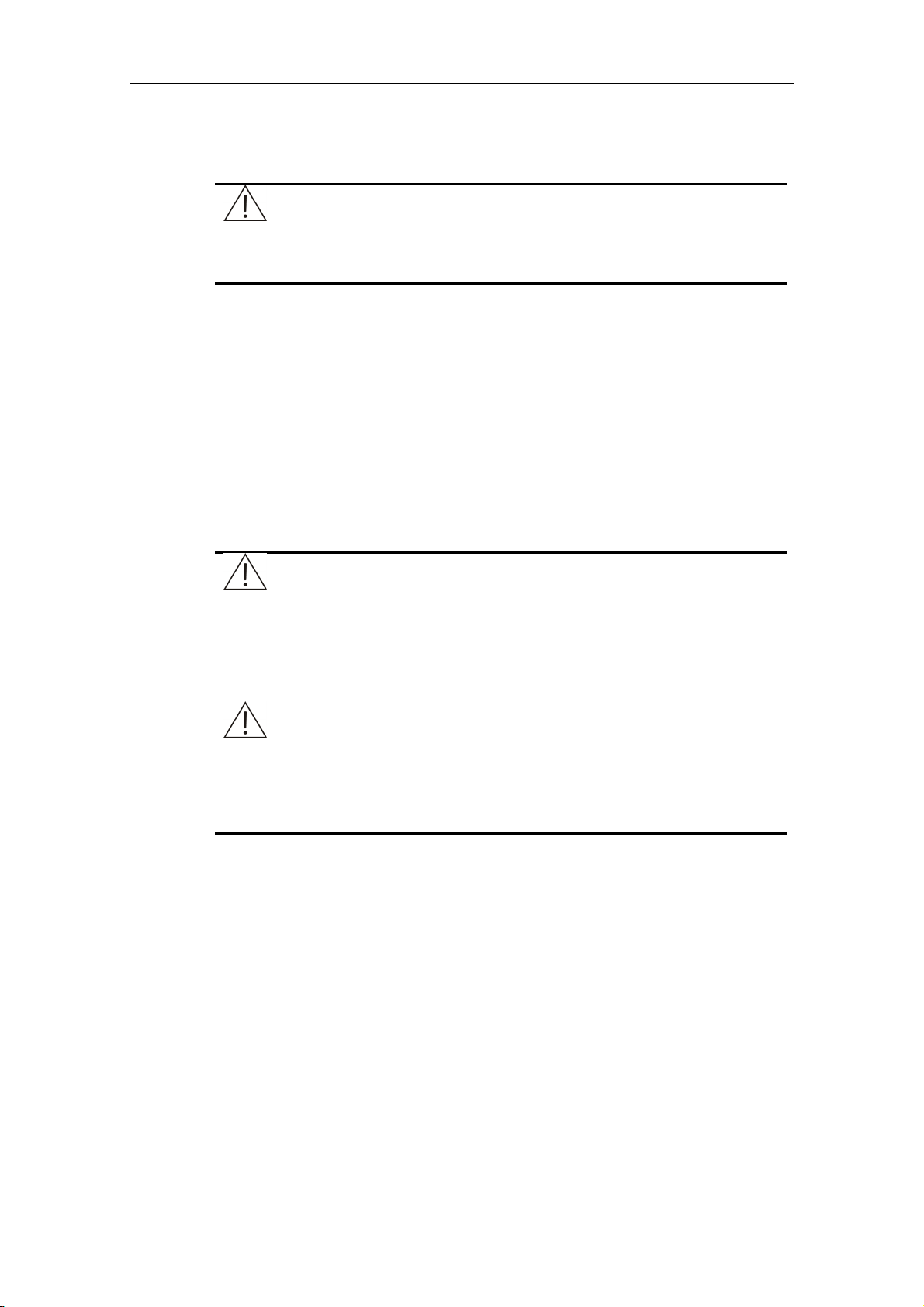
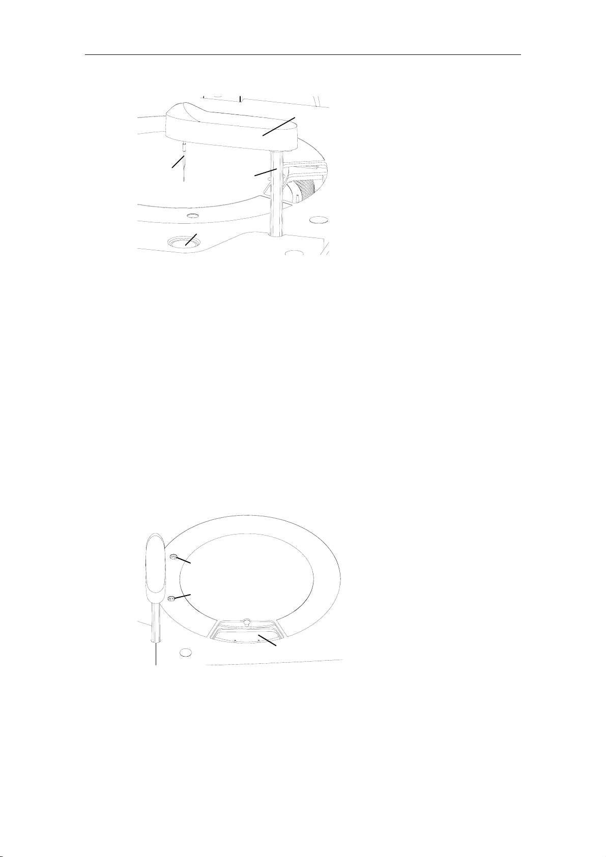
Figure 1-3 Dispenser
Arm
Rotor
Probe
The probe aspirates certain amount of sample from the designated sample tube, or
reagent from the designated reagent bottle, and then dispenses them into the
designated cuvette on the reaction disk.
After dispensing the sample or the reagent, the probe moves to the wash well for
cleaning.
Sample volume: 3µl-45µl; precision: 0.5µl.
Reagent volume: 30µl -450µl; precision: 1µl.
The dispenser is capable of preheating the reagent, detecting the sample/reagent
level, capable of tracking level and protecting against collision in the vertical
direction.
Wash Well
1.1.1.3 Mixer
The mixer is composed of a mixing bar, arm and rotor.
WARNING:
When the analyzing unit is in operation, do not place any part of your
body or any obstacle in the route the arm moves. Otherwise, it may
lead to personnel injury or equipment damage.
1-4
System Description
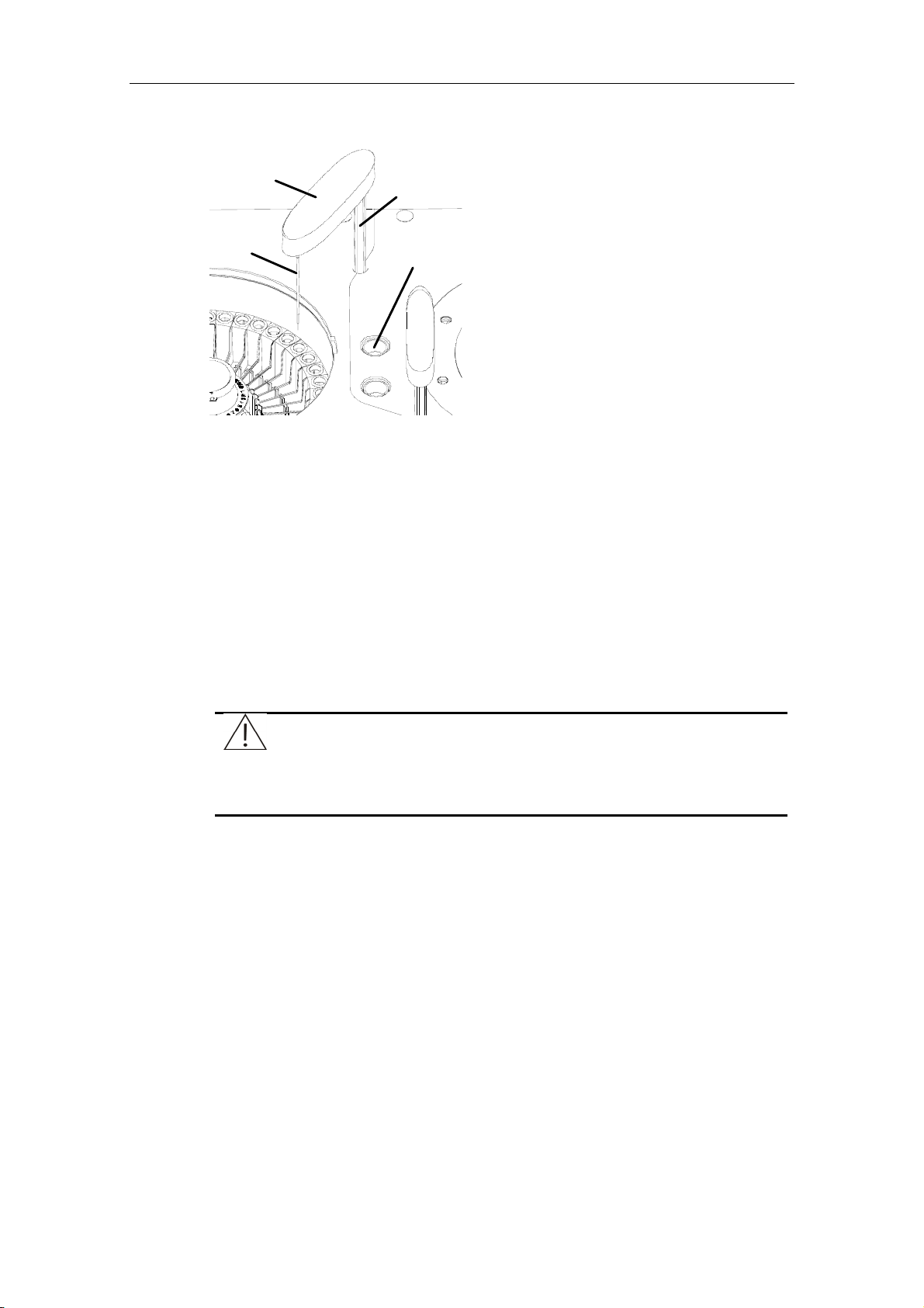
Figure 1-4 Mixer
Arm
Mixing Bar
Wash Well
The mixing bar thoroughly stirs the reaction mixture (reagent and sample) in the
cuvette. After stirring, it moves to the wash well for cleaning.
For the single-reagent test, the mixer starts to work after the sample is dispensed
into the cuvette.
For the double-reagent test, the mixer starts to work after the sample or the second
reagent is dispensed into the cuvette.
1.1.1.4 Reaction Disk
The reaction disk holds the cuvettes, in which the sample reacts with the reagent(s)
and colorimetric readings are taken.
Rotor
Figure 1-5 Reaction disk
Dispensing Position
Mixing Position
Reaction Disk
The reaction disk can hold 8 cuvette segments (80 cuvettes).
During the analyzing process, the reaction disk rotates to dispensing position or
mixing position as needed. The colorimetric readings are taken when the specified
cuvette passes through the optical axis.
The cuvettes adopted are
1-5
System Description
Disposable;
5mm×6mm×30mm (5mm optical path);
900µl (capable of holding 180-500µl of the reaction mixture).
The reaction disk is placed in the temperature-controlled chamber, which keeps a
constant temperature at 37±0.3˚С.
BIOHAZARD:
Be sure to dispose of the used cuvettes in compliance with the local
regulations.
CAUTION:
The cuvettes should not be re-used. Otherwise, the system
performance may be degraded.
1.1.1.5 Photometric System
The photometric system, which locates in the analyzing unit, measures the
absorbance of the reaction mixture in the cuvette.
The photometric system provides 8 wavelengths: 340nm, 405nm, 450nm, 510nm,
546nm, 578nm, 630nm, 670nm, 700nm (optional).
1.1.2 Operation Unit
The operation unit is a computer with the control software of BS-200 Chemistry
Analyzer installed. It manages running of the analyzing unit, as well as operation and
data processing.
1.1.3 Output Unit
The output unit is a printer that prints out the test results and other data.
1.2 Software Introduction
NOTE:
In this manual, “click” refers to moving the pointer of the mouse to the
desired item and click the left button of the mouse.
1.2.1 Software Interface
The interface of the control software is shown in Figure 1-6.
1-6
System Description
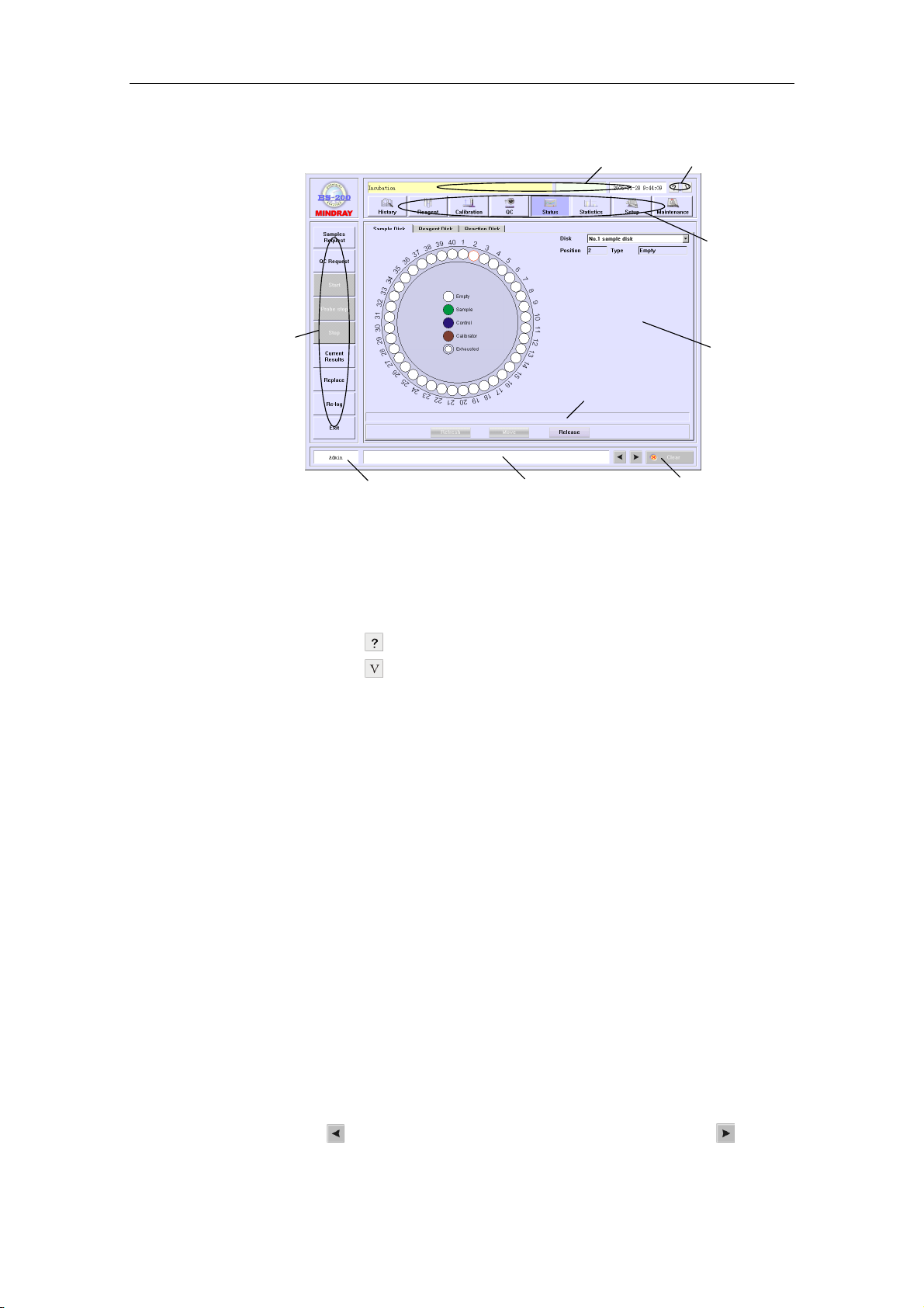
Figure 1-6 Interface of the control software
System Status Area Small Buttons Area
37.0
Group Buttons
Area
Shortcut Buttons
Area
Operator Area
Comment Area
Warning Messages Area
Clear Button
Working Page
Area
System status area
This area displays the system status, current temperature of the reaction disk and
current time.
Small buttons area
Click the small button
Click the small button
, and the BS-200 Operation Manual will be displayed.
, and the version of software will be displayed.
Group buttons area
Displays group buttons which include History, Reagent, Calibration, QC, Status,
Statistics, Setup and Maintenance.
Click a group button, and a relevant working page will be displayed.
Shortcut buttons area
Displays shortcut buttons which include Sample Request, QC Request, Start,
Probe Stop, Stop, Current Results, Replace, Re-log and Exit.
Click a shortcut button, and corresponding operation will be performed.
Working page area
Displays values and graphs for parameters, procedures and results.
When the pointer of the mouse points to an element in current working page, the
comment area on the lower part of the working page will display the explanation of
the element.
Operator area
Displays the name of the current operator.
Warning messages area
Displays the warning and error messages.
Click the button
to view the previous message, and click the button to view
the next one.
1-7
System Description
Clear button
Click the button
area.
to clear contents displayed in the warning messages
1.2.2 Main Interface Components
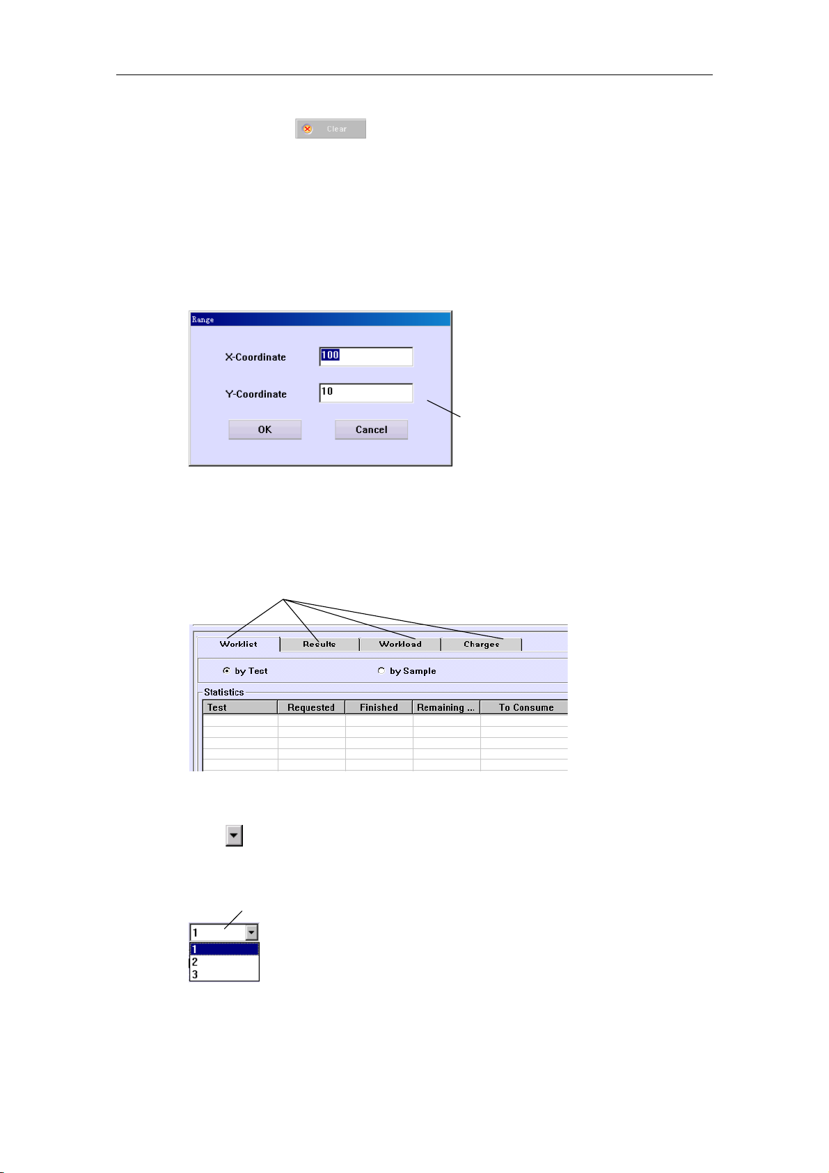
Dialog box
The dialog box is one of the most common components. See the following example:
Tab
See the figure below for an example. Click a tab and you can access the working
page that it indexes.
Dialog Box
Tabs
Drop-down list box
Click
select it.
Drop-down List Box
and a list will display, as the figure below shows. Click the desired item to
Button
Click a button and you can access the function it indexes, as the figure below shows.
1-8
System Description
Button
Radio button
Click a radio button to select the option it represents.
Note that for a given group of radio buttons, you can only select one of them. See
the figure below.
Radio Buttons
Check box
Click a check box to select the option it represents and click it again to deselect it.
Note that for a given group of check boxes, you can choose more than one of them
at one time. See the figure below.
Check Boxes
Edit box
You can enter characters in the edit box from keyboard. See the figure below.
There’re two types of edit boxes, one can only accept characters input from the
keyboard, while the other can accept characters not only input from the keyboard but
also selected by clicking
Edit Box
Edit Box
or .
Scroll bar
When the contents to be displayed are too many for one screen, the scroll bar will
appear to help you see the hidden contents.
Move the pointer to the scroll bar, press left button of the mouse and hold it, then you
can drag the scroll bar left/right or up/down to see the hidden contents.
1-9
System Description
Scroll Bar
Scroll Bar
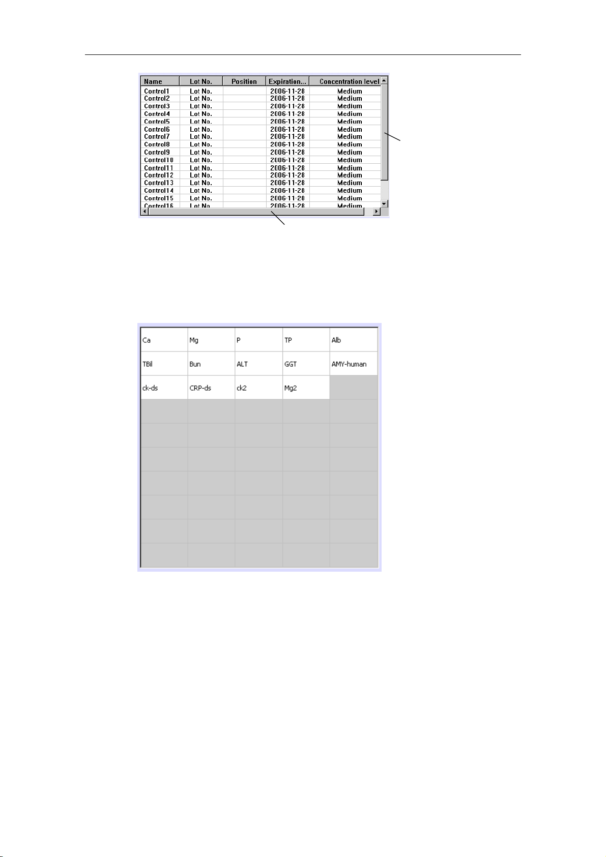
List
The list can list the names of tests, profiles or others, as the figure below shows.
Click a test to select it, and click it again to deselect.
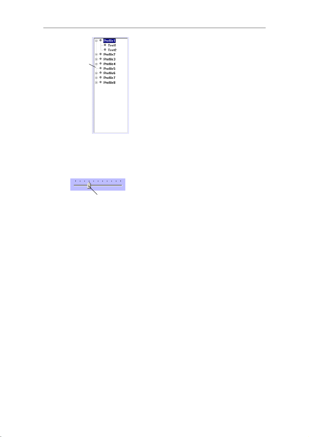
List tree
List tree can list the affiliation among options, as the figure below shows.
Click the “-” to hide the subordinate options, and the “-” becomes “+”.
Click the “+” to expand the subordinate options and display their affiliation, then “+”
turns to be “-”.
If an option has no subordinate options, there is no “+” or “-” to the left of it.
1-10
System Description
List Tree
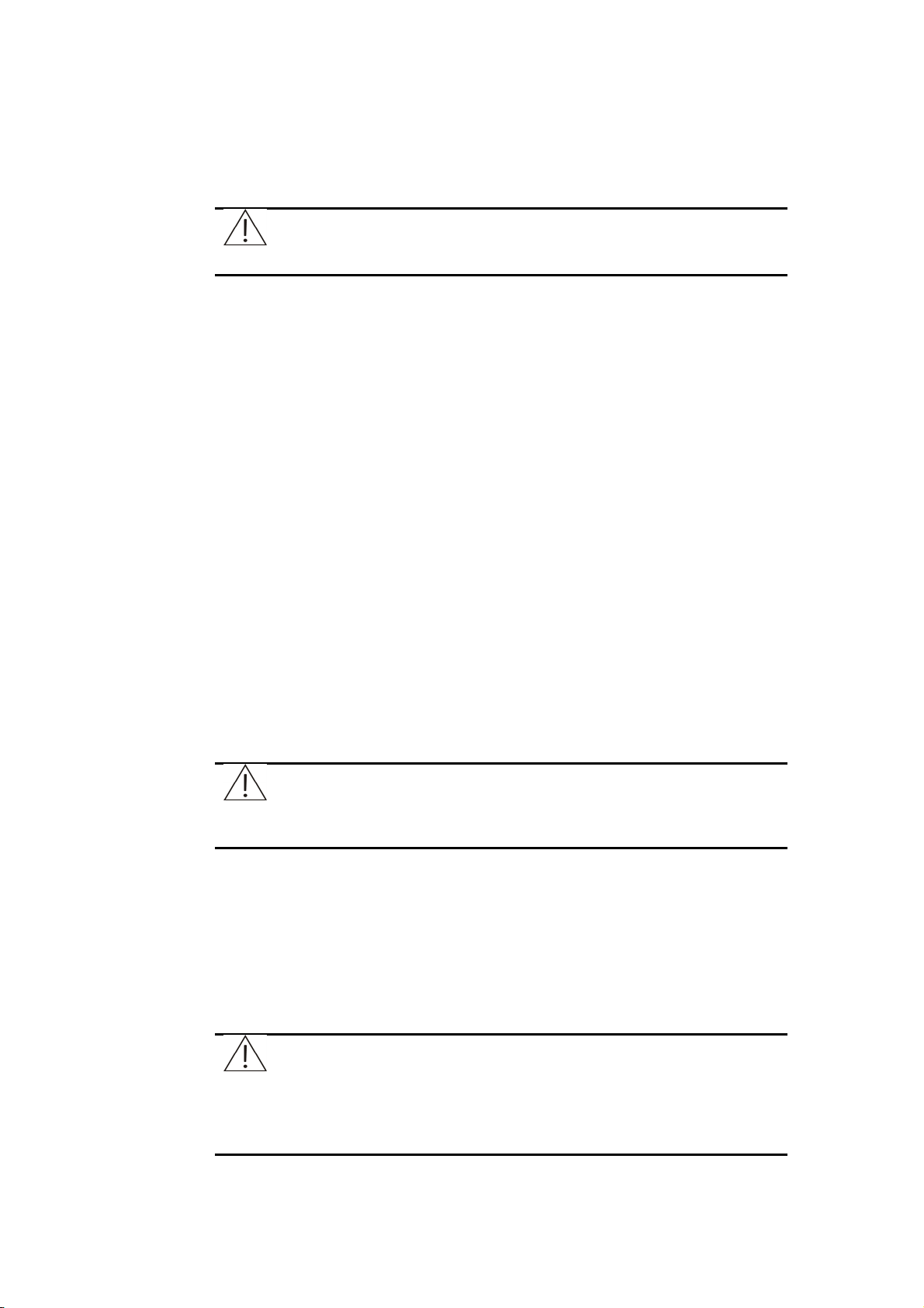
Drag bar
Drag bar is used to select a level continuously, as the figure below shows.
Click the drag bar and hold it, then you can drag it to the position needed.
Drag Bar
1-11

2 Installation
WARNING:
The system should be installed by Mindray-authorized personnel only.
The system should be installed by Mindray-authorized personnel only, and you
should prepare a proper site for installation.
If you need to move the system to another site, please contact Mindray Service
Department or your local distributor, who are the appropriate people for the moving
job.
2.1 Unpacking
When you receive the system, carefully inspect the package. If you see any signs of
mishandling or damage, file a claim immediately with Mindray Service Department or
your local distributor.
After opening the package, check the delivered goods against the packing list as
well as the appearance of the system. If you find anything missing or damaged, alert
Mindray Service Department or your local distributor immediately.
2.2 Installation Requirements
CAUTION:
Make sure the system is installed in a place meeting the following
requirements. Otherwise, it will not perform as promised.
2.2.1 Installation Environment Requirements
This system is for indoor use only.
The bearing platform (or ground) should be level (gradient less than 1/200).
The bearing platform (or ground) should be able to bear 100Kg weight.
The installation site should be well ventilated.
CAUTION:
The system radiates heat when operating. A well-ventilated
environment helps keep the room temperature stable. Use ventilation
equipment if necessary. But if so, be sure not to expose the system to
the direct draft that may lead to unreliable results.
2-1

Installation
The site should be free of dust as much as possible.
The site should not be in direct sun.
The site should not be near a heat or draft source.
The site should be free of corrosive gas and flammable gas.
The bearing platform (or ground) should be free of vibration.
The site should not be disturbed by large noise or power supply.
The system should not be placed near brush-type motors and electrical contacts
that are frequently turned on and off.
Do not use such devices as mobile phones or radio transmitters near the system.
Electromagnetic waves generated by those devices may interfere with operation
of the system.
The altitude height of the site should be lower than 2000 meters.
WARNING:
When the forward or backward gradient is more than 8 degrees, the
system may tip over. Be sure to take proper measures when
transporting and storing it.
2.2.2 Power Requirements
Power supply: AC 110-130V/200-240V±10%, 50/60Hz, three-wire power cord
and properly grounded.
The system should be connected to a properly grounded power socket.
The distance between the power socket and the system should be less than 3
meters.
WARNING:
Make sure the power socket is grounded correctly. Improper grounding
may lead to electric shock and/or equipment damage.
Be sure to connect the system to a power socket that meets the
above-mentioned requirements and has a proper fuse installed.
2.2.3 Temperature and Humidity Requirements
Storage temperature and humidity
The system should be stored in a 0˚C-40˚C environment with fluctuation less than
±2˚C /H.
The relative humidity should be between 30%RH-80%RH and with no
condensation.
CAUTION:
Storing the system in an environment other than the specified may
damage the system.
2-2

Installation
Operating temperature and humidity
When the system is running, be sure to fix the ambient temperature between
15˚C -30˚C with fluctuation less than ±2˚C /H.
The ambient humidity should be between 35%RH-80%RH and with no
condensation.
CAUTION:
Operating the system in an environment other than the specified may
lead to unreliable test results.
If the temperature or relative humidity does not meet the
above-mentioned requirements, be sure to use air-conditioning
equipment.
2.2.4 Water Supply and Drain Requirements
The water must meet requirements of the CAP Type II water.
The water temperature should be between 5-50˚C.
If water-purifying equipment is used, the pressure at the source should be
between 49kPa-392kPa.
BIOHAZARD:
Be sure to dispose of the waste according to the local regulations.
CAUTION:
The water must meet requirements of the CAP Type II water,
otherwise insufficiently purified water may result in misleading
measurement.
2.2.5 Space and Accessibility Requirements
The system should be installed and used meeting the space and accessibility
requirements as shown below.
2-3

Installation
Figure 2-1 Space and accessibility requirements
Maximum 2500
Minimum 500
Operation
680
Analyzing Unit
Unit
Wall
860
Minimum 500
Minimum 500 Minimum 500
F
R
O
N
T
2.3 Connecting Deionized Water Tank
BIOHAZARD:
Wear gloves and lab coat and, if necessary, goggles.
CAUTION:
When placing the deionized water tank, ensure the top of the tank is
lower than the bottom of the upper cabinet.
Ensure the deionized water pickup tube is not blocked, bent, or
twisted.
Unit: mm
1 Place the Power to OFF.
2 Put the pickup tubes and the sensor into the deionized water tank, and
then turn the cap of the deionized water tank clockwise.
3 Put the deionized water tank on an appropriate place.
4 Plug the red and the green connectors to their counterparts marked
DEIONIZED WATER on the rear side of the analyzing unit and turn the
connectors clockwise until secure.
5 Plug the sensor connector to its counterpart marked D-SENSOR on the
rear side of the analyzing unit and turn it clockwise until secure.
2-4

Installation
2.4 Connecting Waste Tank
BIOHAZARD:
Wear gloves and lab coat and, if necessary, goggles.
CAUTION:
When placing the waste tank, ensure the top of the tank is lower than
the bottom of the upper cabinet.
Ensure the waste tube is over the tank and not blocked, bent, or
twisted. A blocked, bent or twisted waste tube may lead to wastewater
overflow that may damage the analyzer.
1 Place the Power to OFF.
2 Put the waste tube and the sensor into the waste tank, then turn the cap
of the waste tank clockwise.
3 Put the waste tank on an appropriate place.
4 Keep pressing the pin on the waste connector marked WASTE on the
rear side of the analyzing unit and grab the waste tap and insert it to the
connector.
5 Plug the sensor connector to its counterpart marked W-SENSOR on the
rear side of the analyzing unit and turn it clockwise until secure.
2.5 Installing/Removing Sample/Reagent Disk
WARNING:
Before installing/removing the sample/reagent disk, make sure the
Power is placed to OFF and the sample/reagent disk has been
stopped.
BIOHAZARD:
Wear gloves and lab coat and, if necessary, goggles.
Figure 2-2 Structure of the sample/reagent disk
Bottle Holder
Handwheel
Tube Holder
Handle
2-5

Installation
To install the sample/reagent disk, keep the handle at the vertical position, align the
hole of the handwheel to the pin of the rotor, gently lower the sample/reagent disk all
the way down and move the handle back to the horizontal position to secure the disk
to the rotor.
To remove the sample/reagent disk, first shift the handle from the horizontal position
to the vertical position. Then grab the handle or handwheel and pull the disk upward
to remove it from the rotor.
CAUTION:
Make sure the sample/reagent disk cover is closed, otherwise cooling
effect of the refrigerator will be degraded and the sample probe may
be damaged.
Before running the system, make sure that the sample/reagent disk
cover is closed and the round red mark on the cover is aligned with its
counterpart on the panel. Otherwise the sample probe may be
damaged.
NOTE:
The sample/reagent compartment and the sample/reagent disk may
be contaminated when being used. If samples spill in the compartment
or on the disk, wipe them with cloth soaked with water or disinfector
after placing the Power to OFF.
2.6 Installing/Removing Sample Tubes
WARNING:
Before installing/removing the sample tubes, make sure the
sample/reagent disk and the probe have been stopped.
Do not use sample tubes other than the specified ones.
BIOHAZARD:
Wear gloves and lab coat and, if necessary, goggles.
To load sample tubes, insert the tube into the tube holder until the bottom of the tube
contacts the groove of the tube rack.
To remove sample tubes, grab the tube and pull it upward to remove it from the tube
holder.
2-6

Installation
2.7 Installing/Removing Reagent Bottles
WARNING:
Before installing/removing the reagent bottles, make sure the
sample/reagent disk and the probe have been stopped.
Do not use reagent bottles other than the specified.
BIOHAZARD:
Wear gloves and lab coat and, if necessary, goggles.
To load reagent bottles, insert the bottle into the bottle holder until the bottom of the
bottle contacts the groove of the holder.
To remove the reagent bottles, grab the bottle and pull it upward to remove it from
the bottle holder.
2.8 Installing/Removing Cuvettes
BIOHAZARD:
Wear gloves and lab coat and, if necessary, goggles.
Be sure to dispose of the used cuvettes in compliance with the local
regulations.
Figure 2-3 Reaction disk assembly
Button
Small Window
Pins
To install cuvettes, push forward the button on the small window of the reaction disk
to open it, then align the holes on the cuvette segment to the pins on reaction disk
and put the segment on the disk. After installing, close the small window.
To remove cuvettes, push forward the button on the small window of the reaction
disk to open it, and then take out cuvette segments.
2-7

3 Basic Operations
This chapter provides step-by-step procedures to operate the analyzer for basic
tasks.
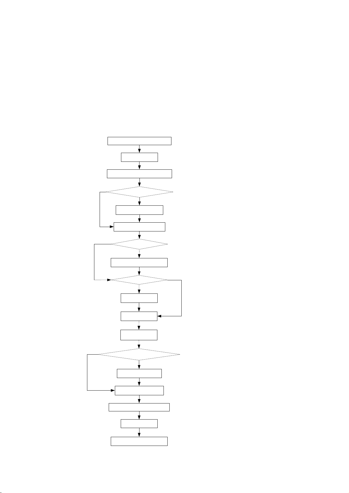
3.1 Daily Procedure
Checking before power-on
Power-on
Start the control software
Set parameters?
Yes
No
Set parameters
No
No
Prepare for analysis
Reagent blank?
Yes
Reagent blank
Calibrate?
Yes
Calibrate
QC
Samples
Edit sample results?
Yes
Edit sample results
Print sample results
No
Exit the control software
Shutdown
Checking after shutdown
3-1

Basic Operations
3.2 Preparing for Analysis
3.2.1 Checking before Startup
You should do the following operations before starting the analyzer.
BIOHAZARD:
Wear gloves and lab coat and, if necessary, goggles when performing
the following operations.
1 Check the power supply and make sure it can supply proper voltage for the
analyzer.
2 Check the connections among the analyzing unit, operation unit and printer.
Make sure the connections are right and secure. Check the power cords of
the analyzing unit, operation unit and printer and make sure they are well
connected to the power sockets.
3 Check and make sure sufficient printing paper is prepared for the printer.
4 Ensure a detergent is in position 39 on the reagent disk and sufficient
distilled water is in position 40 on the reagent disk.
NOTE:
Mindray has specified the following detergents:
Acid: 0.1mol/l hydrochloric acid;
Alkaline: 0.5% (V/V) javel water.
Do not mix the acid detergent with the alkaline one.
Be sure to use the detergent recommended by Mindray.
Otherwise, proper result may not be obtained.
Mindray recommends the acid and alkaline detergents be used
alternately. For instance, if the acid detergent has been used
for the last time, the alkaline one had better be used for this
time.
5 Refer to 5.2.3 Checking Connection of Deionized Water for instructions of
checking connection of deionized water.
6 Refer to 5.2.4 Checking Connection of Wastewater for instructions of
checking connection of wastewater.
7 Refer to 5.2.5 Checking Syringe for instructions of checking the syringe.
8 Refer to 5.2.6 Checking Probe (step 1- 5) for instructions of checking the
probe.
9 Refer to 5.2.7 Checking Mixing Bar (step 1- 3) for instructions of checking
the mixing bar.
3-2
Basic Operations
10 Refer to 5.2.1 Checking Remaining Deionized Water for instructions of
checking the deionized water tank.
11 Ensure the waste tank is empty. If it is not empty, refer to 5.2.2 Emptying
Waste Tank for instructions of emptying the waste tank.
3.2.2 Power-on
Power on the analyzer in the sequence presented below:
1 Place the MAIN POWER to ON.
2 Place the Power to ON.
3 Press the power button on the monitor of the operation unit.
4 Press the power button on the computer of the operation unit.
5 Press the power button of the printer.
3.2.3 Starting the Control Software
1 After you have logged on the Windows operating system, double-click the
shortcut icon of the control software on the desktop or select the program of
the control software from [Start] to startup the control software.
After startup, the analyzer will check automatically the operation system and
resolution of the screen, close screen saver, check color configuration,
initialize database and examine the printer.
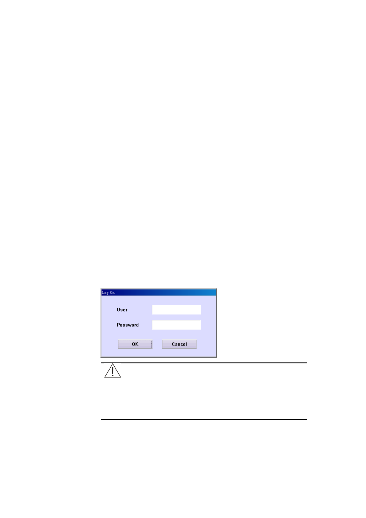
When checking is finished, the following dialog box will pop up to ask you to
enter the username and password, and then click OK.
NOTE:
The resolution of the screen must be 1024x768.
The color configuration must be at least 8 bits.
The username of the system administrator is “Admin” which is
same as the initial password.
3-3

Basic Operations
2 Select a serial port from Serial Port in the Startup dialog box, then click
Start to initialize the system. After that, operate according to the screen
prompt until the main screen of the control software is displayed.
CAUTION:
You may not start the analysis until the system status area of the
screen displays “Standby” and the analyzer has been turned on for at
least 30 minutes.
NOTE:
Refer to 5.2.6 Checking Probe (step 6 - 9) for instructions of checking
the probe.
Refer to 5.2.7 Checking Mixing Bar (step 4 - 5) for instructions of
checking the mixing bar.
3.2.4 Setting Up the Analyzer
The analyzer will not function properly unless it is properly set up.
You must complete all the following settings if this is the first time the analyzer being
used.
Before requesting the tests, you must finish the following settings:
To set the options regarding the basic parameters of the system and data
dictionaries, refer to 4.16.6 System.
To set the options regarding the hospital information, refer to 4.16.7 Hospital.
To set the options regarding parameters of calibrators, refer to 4.12.3 Calibrator.
To set the options regarding parameters of controls, refer to 4.13.4 Control.
To set the options regarding test parameters, reference, calibration rule and
quality control (QC) rule, refer to 4.16.1 Test.
To set the options regarding the reagent parameters, refer to 4.11 Reagent.
To set the options regarding the carryover information among tests, refer to 4.16.5
Carryover.
To set the options regarding the printing parameters, refer to 4.16.9 Print.
3-4
Basic Operations
3.2.5 Preparing Reagents
Load reagent bottles to their assigned positions on the reagent disk, and then open
the bottles.
WARNING:
The probe tip is sharp and can cause puncture wounds. To prevent
injury, exercise caution when working around the probe.
BIOHAZARD:
Wear gloves and lab coat and, if necessary, goggles.
3.3 Starting Analysis
3.3.1 Reagent Blank
CAUTION:
The reagent blank is vital to obtaining correct analysis results. The
blank results can assist in determining whether the reagents have
expired, or whether the reaction background should be deducted, and
in eliminating the absorbance changes caused by the reagents
themselves. Mindray recommends the reagent blank be run on a daily
base.
The analyzer will use the result of the previous reagent blank run for
double-reagent tests that use endpoint method if no new reagent blank
result is available.
To request reagent blanks, refer to 4.12.1 Calibration Request.
To run reagent blanks, refer to 4.3 Start.
To view reagent blank results, refer to 4.12.2 Results.
3.3.2 Calibration
CAUTION:
You need to run the calibration again when you change reagent lots,
test parameters, lamp or other analysis conditions.
To request calibrations, refer to 4.12.1 Calibration Request.
After requesting calibrations, you should load corresponding calibrators to their
assigned positions on the sample disk.
3-5

Basic Operations
To run calibrations, refer to 4.3 Start.
To view calibration results, refer to 4.12.2 Results.
3.3.3 QC
To request QCs, refer to 4.2 QC Request.
After requesting QCs, you should load corresponding controls to their assigned
positions on the sample disk.
To run QCs, refer to 4.3 Start.
CAUTION:
If Auto QC on the System screen is selected and Interval for QC on
the Test screen is not 0, the analyzer will automatically insert QC
tests among sample tests.
To check QC results, refer to 4.13.1 Real-time QC, 4.13.2 Daily QC and 4.13.3 Day
to Day QC.
3.3.4 Samples
To request samples, refer to 4.1 Sample Request.
After requesting, you should load corresponding samples to their assigned positions
on the sample disk.
NOTE:
STAT samples are requested in the same way as routine ones except
that STAT on the Sample Request screen should be selected when
requesting.
CAUTION:
Ensure the samples are loaded to correct positions. Otherwise, you
cannot acquire correct results.
To run samples, refer to 4.3 Start.
To check sample results, refer to 4.6 Current Results or 4.10 History.
3-6

Basic Operations
3.4 Processing Results
3.4.1 Editing Results of Samples
CAUTION:
Sample results can only be edited by authorized personnel.
To edit results of one or more sample runs, refer to 4.10.4 Edit Results.
To make linear transform or calibration transform to the results of one or more tests,
refer to 4.10.3 Compensate Results.
3.4.2 Printing Results of Samples
To print sample results, refer to 4.10.7 Print Results.
3.5 Finishing Analysis
3.5.1 Exiting the Control Software
When you have finished all analyses and the system is in standby status, you can
exit the control software as instructed by 4.9 Exit.
3.5.2 Shutdown
After exiting the Windows operating system, switch off the following powers in the
presented order:
1 Turn off the printer.
2 Turn off the monitor of the operation unit.
3 Place the Power to OFF.
NOTE:
The refrigerator still functions after the Power is placed to OFF. To shut
down the refrigerator, place the MAIN POWER to OFF.
3-7

Basic Operations
3.5.3 Operations after Shutdown
BIOHAZARD:
Wear gloves and lab coat and, if necessary, goggles when performing
the following operations.
1 Cover every reagent bottle on the sample/reagent disk.
NOTE:
If the MAIN POWER is placed to OFF, take the reagents from
the reagent disk and put them into an external refrigerator.
2 Remove the calibrators, controls and samples from the sample/reagent disk.
3 Empty the waste tank. Refer to 5.2.2 Emptying Waste Tank for details.
4 Check the surface of the analyzing unit for stains and wipe them off with
clean soft cloth, if any.
3-8

4 Advanced Operations
The chapter presents an introduction of the control software of the analyzer by
shortcut buttons and group buttons.
4.1 Sample Request
Click the Samples Request button to enter the Sample Request screen, as shown
in Figure 4-1, where you can check the requested samples and request new ones.
Figure 4-1 Sample Request Screen
NOTE:
In the Tests field, different background colors of the test refer to
different meanings:
Blue means the test is selected;
White means the test is selectable;
Gray means the test is unselectable, and if the pointer of the mouse is
stopped on it for a while, the system will remind you of the reason why
it is unselectable.
The Profiles field and the Off-system Tests field are the same as the
Tests field.
4-1

Advanced Operations
The following table explains the parameters on the screen.
Parameter Description
Sample Disk To select a virtual sample disk on which the sample locates.
Samples It refers to the requested samples or the ones being requested
No. It refers to the sample ID, which includes the starting No. and
on the selected sample disk.
”Tests” refers to multiplication of No. of tests for the sample and
No. of replicates.
ending No.
The No. can be assigned by the system automatically, or entered
by the operator manually.
You should enter the starting No. in the first edit box and the
ending No. in the second one.
If the starting No. is same as the ending No., the system will
consider it as one sample by default. When the latter is greater
than the former, it indicates a batch of samples.
You must use different No. for different samples within one day.
Position It refers to position of the sample on the selected virtual sample
disk.
The position can be assigned by the system automatically, or
selected from the drop-down list box by the operator manually.
For single sample, it refers to the position of this sample; for a
batch of samples, it refers to the position of the sample with
starting No., and positions of other samples will be assigned by
the system accordingly.
Replicates It refers to times of the same sample run. 1 is default, which
means once only.
Samp. Type It includes Serum, Plasma, Urine and Other.
Barcode Barcode information of the selected sample.
STAT When selected, it means that the sample(s) currently requested
are stat sample(s).
Samp. Blank When selected, it refers to running a sample blank before
starting analysis. The system tests the mixed absorbance
(endpoint) or the absorbance change rate (non-endpoint) of the
mixture of the sample and the distilled water instead of reagent.
4-2

Advanced Operations
The following table introduces the buttons on the screen.
Button Function
Details After selecting a sample from Samples, click this button to pop
up the Sample Information dialog box, where you can check and edit the detailed information of the sample.
For more information about the Sample Information dialog box,
refer to 4.1.1 Sample Information.
Delete After selecting a sample from Samples, click this button to pop
up the Delete Sample dialog box, where you can delete the
sample or release its position.
This button is not available for the sample being requested.
For more information about the Delete Sample dialog box, refer
to 4.1.2 Delete a Sample.
Change
Position
Previous Click this button to display the information of the previous sample
Next Click this button to display the information of the next sample (in
Cancel After requesting new samples or modifying the information of a
OK After requesting new samples or modifying the information of a
Click this button to pop up the Exchange Positions dialog box,
where you can change positions of samples.
For more information about the Exchange Positions dialog box,
refer to 4.1.3 Change Position.
(in requesting order).
requesting order).
requested sample, click this button to cancel the requests or
modification.
Refer to 4.1.4 Requesting Samples or Modifying Information
for detailed operations.
requested sample, click this button to finish requesting or save
modification.
Refer to 4.1.4 Requesting Samples or Modifying Information
for detailed operations.
NOTE:
When re-requesting tests for the requested sample, the tests which
have been requested for the sample and are not requested this time
will be invalidated, no matter the tests which have been requested for
the sample have been run or not.
4.1.1 Sample Information
At the Sample Request screen, click Details to pop up the Sample Information
dialog box, as shown in Figure 4-2, where you can check and edit the detailed
information of the sample.
4-3

Advanced Operations
Figure 4-2 Sample Information Dialog Box
The following table explains the parameters of the Sample Information dialog box.
Parameter Description
Sample ID No. of the sample. It cannot be edited.
Type It includes Serum, Plasma, Urine and Other.
Replicates It refers to times of sample run. It cannot be edited.
Position The first edit box is No. of virtual sample disk, and the second is
the sample position. Both of them cannot be edited.
Sent from The department to which the sender belongs.
Sender Name of the sender.
Tested by The department to which the tester belongs.
Tester Name of the tester.
Characteris. Characteristic of the sample. It includes blank (none), Hemolysis
and Jaundice.
Blood Type Blood type of the sample.
Patient Name of the patient.
Age Age of the patient.
Gender Gender of the patient.
4-4

Advanced Operations
Parameter Description
Chart No. Chart No. of the patient.
Treated by The department where the patient is treated.
Doctor The doctor in charge for the patient.
Area No. No. of the area where the patient stays.
Admis. No. Admission No. of the patient
Bed No. No. of the bed where the patient stays.
Barcode The barcode information of the sample.
Diagnosis The clinical diagnosis to the patient’s disease.
The following table introduces the buttons of the Sample Information dialog box.
Button Function
Previous
Click this button to display the information of the previous
sample.
Next
OK
Cancel
Close
Click this button to display the information of the next sample.
Click this button to save modification to the sample information in
this dialog box.
Click this button to cancel modification to the sample information
in this dialog box.
Click this button to close the Sample Information dialog box.
4.1.2 Delete a Sample
At the Sample Request screen, after selecting a sample in Samples, click Delete to
pop up the Delete Sample dialog box, as shown in Figure 4-3, where you can delete
the selected sample or release its position.
Figure 4-3 Delete Sample Dialog Box
4-5

Advanced Operations
The following table explains the parameters of the dialog box.
Parameter Description
Release
Position
Release the sample position without deleting all tests related to
this sample.
It is available for the tested samples only.
Delete
Sample
The following table introduces the buttons of the dialog box.
Button Function
OK
Cancel
Delete the sample as well as the related tests.
Click this button to release the selected sample position or delete
the sample.
Click this button to cancel the releasing or deletion.
CAUTION:
Deleting a sample will invalidate all tests related to the sample.
4.1.3 Change Position
At the Sample Request screen, click Change Position to pop up the Exchange Positions dialog box, where you can change sample positions on the sample disk.
Figure 4-4 Exchange Positions Dialog Box
4-6

Advanced Operations
The following table introduces the buttons of the dialog box.
Button Function
Probe stop
If the system is in testing status, and the sample position to be
changed or the target position is on the sample disk currently
running, you should first stop the probe, the mixing bar and the
sample/reagent disk.
Click this button to stop the probe, the mixing bar and the
sample/reagent disk, and the button will change into Resume.
After exchanging the positions, click Resume to continue.
Exchange
Close
Select the current and target sample disks the sample locates
from the 1st Sample Disk and 2nd Sample Disk, and select the
current and target positions of the sample from the Positions of
1st Sample Disk and Positions of 2nd Sample Disk. Then
click this button to change the position.
Click this button to exit the Exchange Positions dialog box.
CAUTION:
Do not put the probe, the mixing bar and the sample/reagent disk on
hold for a long time. Otherwise, certain analyses may be affected.
4.1.4 Requesting Samples or Modifying Information
1 Select a sample that is being requested (the samples with “#” in the front) or
has been requested from Samples.
2 You can set sample information and tests for the newly requested samples,
or modify the sample information for the requested sample.
3 If you want to finish requesting or save the modification, click OK; otherwise
click Cancel.
4.2 QC Request
Click the QC Request button to enter the QC Request screen, as shown in Figure 4-5, where you can request QC.
4-7

Advanced Operations
Figure 4-5 QC Request Screen
NOTE:
In the Tests field, different background colors of the test refer to
different meanings:
Blue means the test is selected;
White means the test is selectable;
Gray means the test is unselectable, and if the pointer of the mouse is
stopped on it for a while, the system will remind you of the reason why
it is unselectable.
The following table explains the parameters on the screen.
Parameter Description
Replicates
Times of QC requesting. Default setting is 1, which means once
only. The maximum is 10.
The following table introduces the buttons on the screen.
Button Function
Change
Position
After selecting a control, click this button to pop up the Reset
Position dialog box, where you can reset the position of the
selected control on the sample disk.
For more information about the Reset Position dialog box, refer
to the following text To Reset Position of a Control.
4-8

Advanced Operations
Button Function
OK
After selecting a test(s) in the Tests and setting the Replicates,
click this button to finish requesting.
Cancel
After selecting a test(s) in the Tests and setting the Replicates,
click this button to cancel requesting.
To Reset Position of a Control
At the QC Request screen, after selecting a control, click Change Position to pop
up the Reset Position dialog box, as shown in Figure 4-6, where you can reset the
position of the selected control on the sample disk.
Figure 4-6 Reset Position Dialog Box
The following table explains the parameters of the dialog box.
Parameter Description
Current
New
Disk
Position
Current position of the selected control.
New position of the selected control.
No. of the virtual sample disk.
Void means that the selected control is not on the sample disk.
Position on the selected virtual sample disk.
Void means that the selected control is not on the sample disk.
4-9

Advanced Operations
The following table introduces the buttons of the dialog box.
Button Function
Probe Stop
If the system is in testing status, and the control position to be
changed or the target position is on the sample disk currently
running, you should first stop the probe, the mixing bar and
sample/reagent disk.
Click this button to stop the probe, the mixing bar and the
sample/reagent disk, and the button will change into Resume.
After exchanging the positions, click Resume to continue.
OK
Cancel
4.3 Start
After requesting, click Start to pop up the Condition dialog box, as shown in Figure 4-7, where you can select the virtual sample disk, virtual reagent disk and samples to be tested.
Figure 4-7 Condition Dialog Box
After setting a new sample position, click this button to save the
setting.
After setting a new sample position, click this button to cancel the
setting.
CAUTION:
Do not put the probe, the mixing bar and the sample/reagent disk on
hold for a long time. Otherwise, certain analyses may be affected.
The numbers in the Applied No. field refer to “number of tests to be run/ number of
tests applied” on current sample or reagent disk.
The following table introduces the buttons on the screen.
4-10

Advanced Operations
CAUTION:
Before clicking OK, confirm samples, calibrators, controls and
reagents have been placed in correct positions.
Button Function
OK
After selecting the virtual sample disk, virtual reagent disk and
the samples to be tested, click this button to start analysis.
Cancel
4.4 Probe Stop
When you need to add samples or reagents without stopping current analysis, click Probe Stop to pop up the dialog box, as shown in Figure 4-8, where you can pause the probe, the mixing bar and the sample/reagent disk.
Figure 4-8 Confirm Dialog Box 1
After selecting the virtual sample disk, virtual reagent disk and
the samples to be tested, click this button to cancel selection and
no analysis will be started.
The following table introduces the buttons of the dialog box.
Button Function
OK
Cancel
Click this button to pause the sample probe, the mixing bar and
the sample/reagent disk. On the reaction disk, the tests that have
finished dispensing sample and reagent(s) will continue and the
remaining ones will be paused.
Then the Probe Stop button changes to Resume, click it to pop
up the screen as shown in Figure 4-9. Click OK to resume the
sample probe, the mixing bar and the sample/reagent disk, or
click Cancel to stay.
Click this button to cancel pausing the sample probe, mixing bar
and the sample/reagent disk without affecting the analysis.
4-11
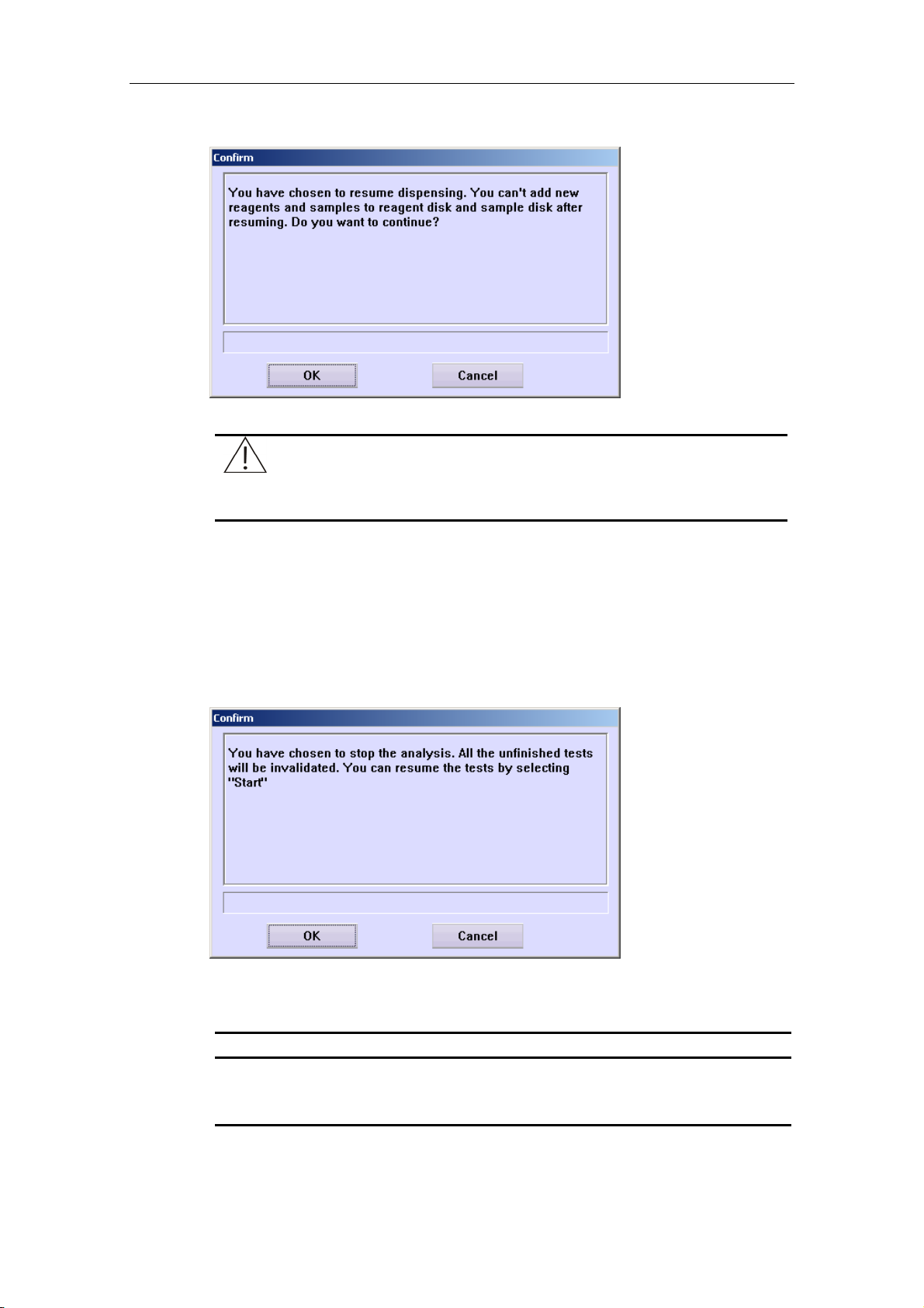
Advanced Operations
Figure 4-9 Confirm Dialog Box 2
CAUTION:
Do not put the probe, the mixing bar and the sample/reagent disk on
hold for a long time. Otherwise, certain analyses may be affected.
4.5 Stop
To stop analysis, click Stop to pop up the dialog box, as shown in Figure 4-10.
Figure 4-10 Confirm Dialog Box 3
The following table introduces the buttons of the dialog box.
Button Function
OK
Cancel
Click this button to stop current analysis.
Click this button to cancel stopping.
4-12
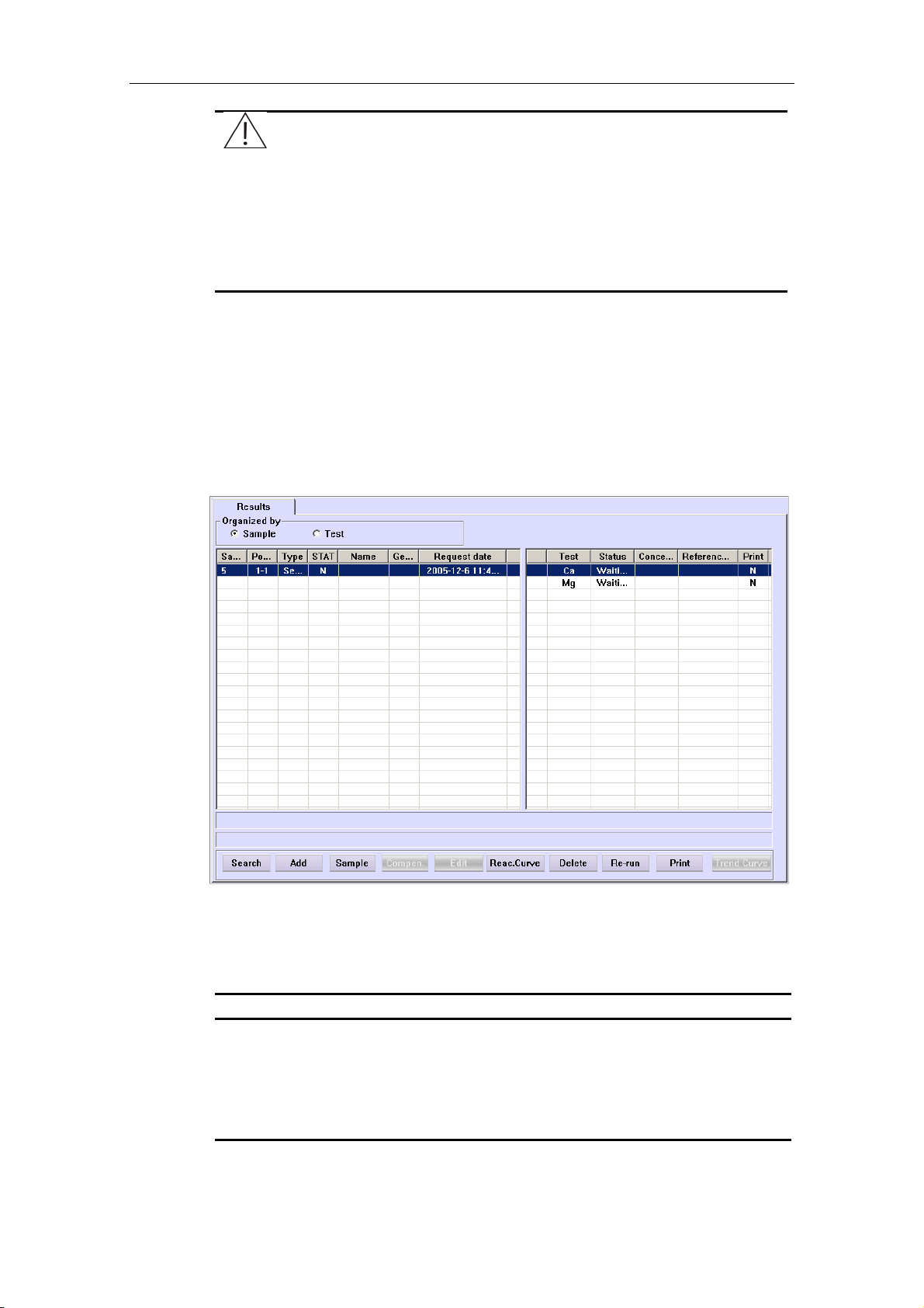
Advanced Operations
CAUTION:
Mindray recommends this stop function not be used unless it is
necessary (for instance the analyzer is experiencing problems).
After the analyzer is stopped, all the tests that have not been finished
will be invalidated.
However, you can continue the requested tests that have not been
finished by clicking the Start button.
4.6 Current Results
Click Current Results to enter the Results screen, as shown in Figure 4-11, where you can view and process the sample results of current day since powering on.
Figure 4-11 Results Screen
Operations of this screen are similar to that in 4.10 History, except that you can only
view and process the sample results of current day since powering on and can
re-run tests. For other operations, refer to 4.10 History.
Button Function
Re-run
After selecting a test and a sample, click this button to pop up the
Re-run dialog box, where you can re-run corresponding sample
test(s).
For more information about the Re-run dialog box, refer to the
following text Re-run.
4-13

Advanced Operations
Re-run
At the Results screen, after selecting a test and a sample, click Re-run to pop up
the Re-run dialog box, as shown in Figure 4-12, where you can re-request
corresponding sample tests of current day since powering on.
Figure 4-12 Re-run Dialog Box
The following table explains the parameters of the dialog box.
Parameter Description
The Sample
Currently
Selected
The Test
All
Re-run all sample tests of the selected sample that have been
finished or have no results.
Re-run the selected sample test for the selected sample only.
It’s only available for the test that has been finished or has no
result.
Re-run the selected sample test for all samples that have been
finished or have no results.
Re-run all the sample tests that have been finished or have no
results.
4-14

Advanced Operations
The following table introduces the buttons of the dialog box.
Button Function
OK
Click this button to pop up the following dialog box.
In this dialog box, click OK to re-run the selected test(s), or click
Cancel to abort re-requesting.
Cancel
4.7 Replace
To replace the cuvettes, click Replace to pop up the dialog box, as shown in Figure 4-13.
Figure 4-13 Confirm Dialog Box 4
Click this button to cancel re-requesting.
The following table introduces the buttons of the dialog box, as shown in Figure
4-13.
Button Function
OK
Cancel
Click this button to pop up the dialog box, as shown in Figure
4-14.
Click this button to cancel replacing.
4-15
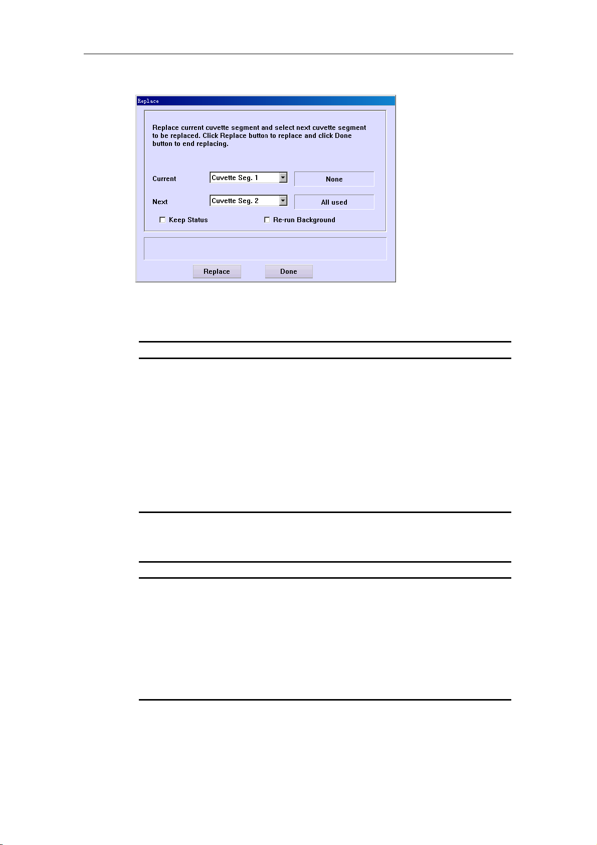
Advanced Operations
Figure 4-14 Replace Dialog Box
The following table explains the parameters of the dialog box, as shown in Figure
4-14.
Parameter Description
Current
Next
Keep Status
Re-run
Background
The following table introduces the buttons of the dialog, as shown in Figure 4-14.
Button Function
Replace
You can load/unload a cuvette segment at this position on the
reaction disk. It cannot be edited.
You will load/unload a cuvette segment at this position on the
reaction disk for the next time.
Select to rotate the reaction disk without loading/unloading
the current cuvette segment, and the status of current cuvette
segment will not be changed.
Select to re-test the background after unloading the Cuvette
Segment 1. Ensure the Cuvette Segment 1 has been
unloaded before selecting.
After setting the parameters, if you have selected Keep Status,
click this button to announce the analyzing unit to execute the
replacing operation.
After setting the parameters, if you have not selected Keep
Status, replace the cuvette segment manually, and then click
this button to announce the analyzing unit to execute the
replacing operation.
Done
Click this button to finish replacing.
4-16
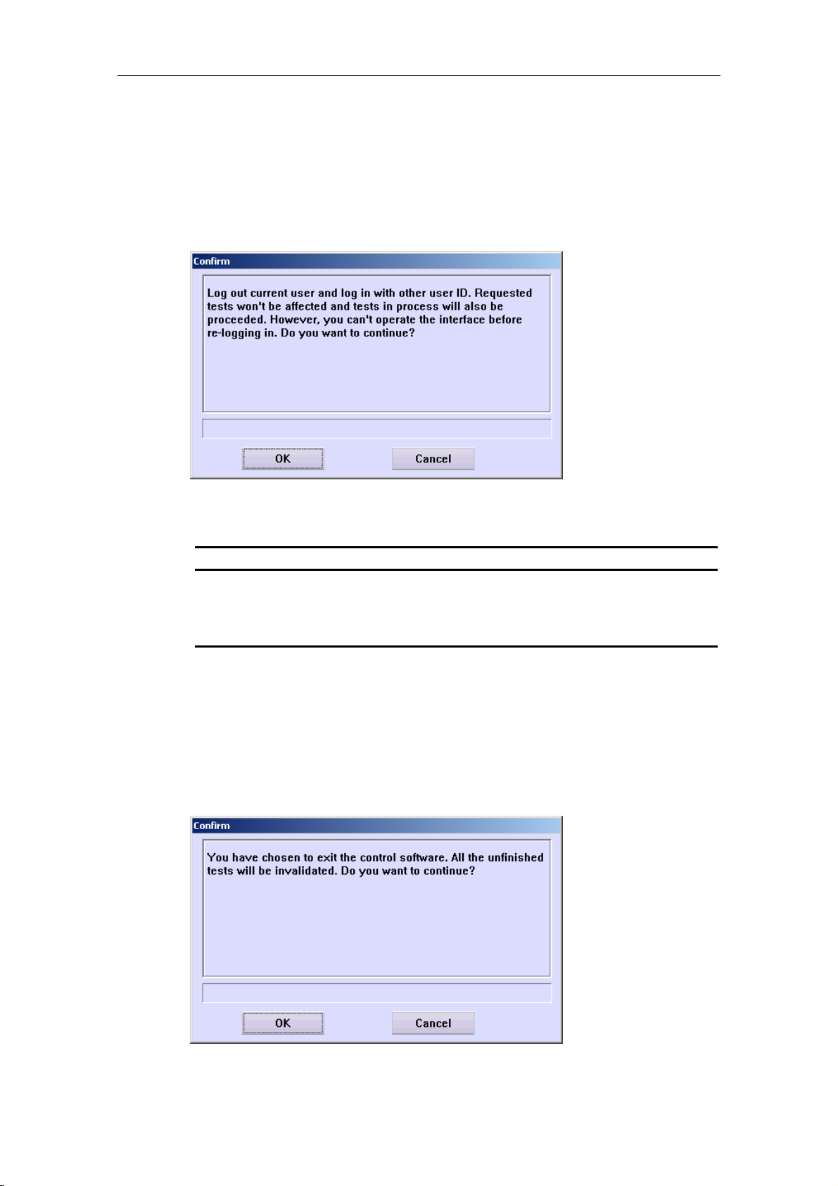
Advanced Operations
4.8 Re-log
If you need to log on the control software with other username, click this button to
pop up the dialog box, as shown in Figure 4-15.
Figure 4-15 Confirm Dialog Box 5
The following table introduces the buttons of the dialog box.
Button Function
OK
Cancel
4.9 Exit
Click Exit to pop up the dialog box, as shown in Figure 4-16.
Figure 4-16 Confirm Dialog Box 6
Click this button to pop up the dialog box to enter the username
and password, and then you can log on as the user.
Click this button to cancel re-logging.
4-17

Advanced Operations
The following table introduces the buttons of the dialog box.
Button Function
OK
Click this button to prepare for exiting the control software and
pop up the dialog box, as shown in Figure 4-17. Then you can
operate according to the dialog box and following ones until
exiting the control software.
Cancel
Figure 4-17 Shutdown Dialog Box
4.10 History
Click History to enter the Results screen, as shown in Figure 4-18, where you can view and edit sample results.
Click this button to cancel exiting.
4-18

Advanced Operations
Figure 4-18 Results Screen
At the Results screen, (Organized by) Sample refers to displaying the results by
sample; (Organized by) Test refers to displaying the results by test.
The following table introduces the buttons on the screen.
Button Function
Search
Add
Sample
Click this button to pop up the Conditions dialog box, where you
can set the searching conditions.
For more information about the Conditions dialog box, refer to
4.10.1 Conditions.
Click this button to pop up the Add Off-system Test Result
dialog box, where you can add off-system test results to
samples.
For more information about the Add Off-system Test Result
dialog box, refer to 4.10.2 Add Off-system Test Results.
After selecting a sample, click this button to pop up the Sample
Information dialog box, where you can view and edit the
information of the selected sample.
For more information about the Sample Information dialog box,
refer to 4.1.1 Sample Information.
4-19

Advanced Operations
Button Function
Compen.
This button is only available when you select (Organized by)
Test.
After selecting a test, click this button to pop up the Compensate
dialog box, where you can edit (including Linear Transform and
Calibration Transform) the searched results of the selected test.
For more information about the Compensate dialog box, refer to
4.10.3 Compensate Results.
Edit
Reac. Curve
Delete
Print
Trend Curve
After selecting a test, click this button to pop up the Edit Result
dialog box, where you can edit the result of the selected test.
For more information about the Edit Result dialog box, refer to
4.10.4 Edit Results.
After selecting a test, click this button to pop up the Reaction
Curve dialog box that displays the reaction curve of the selected
test.
For more information about the Reaction Curve dialog box, refer
to 4.10.5 Reaction Curve.
After selecting a test, click this button to pop up the Delete dialog
box, where you can delete relevant results.
For more information about the Delete dialog box, refer to 4.10.6
Delete Results.
After selecting a test, click this button to pop up the Print dialog
box, where you can print relevant results.
For more information about the Print dialog box, refer to 4.10.7
Print Results.
This button is only available when you select (Organized by)
Test.
4.10.1 Conditions
At the Results screen, click Search to pop up the Conditions dialog box, as shown
in Figure 4-19, where you can enter the conditions to search the results you want.
After selecting a test, click this button to pop up the Result
Trend Curve dialog box, where you can view the result trend
curve of the selected test.
For more information about the Result Trend Curve dialog box,
refer to 4.10.8 Result Trend Curve.
4-20

Advanced Operations
Figure 4-19 Conditions Dialog Box
The following table explains the parameters of the dialog box.
The parameters of this dialog box constitute the searching conditions. Void means
the parameter is exclusive.
Parameter Description
Date
Sample ID
Name
Gender
STAT
Te st
Age
It refers to the date when the test was run.
The first drop-down list box is starting date and the second is
ending date.
No. of the sample.
The first edit box is starting No. and the second is ending No.
Name of the patient.
Gender of the patient.
Whether the sample results to be searched are STAT or not.
Name of the test.
Age of the patients. You must select the unit of the age.
Chart No.
Chart No. of the patients.
The first edit box is starting No. and the second is ending No.
4-21

Advanced Operations
Parameter Description
Admission
No.
Admission No. of the patients.
The first edit box is starting No. and the second is ending No.
Bed No.
Department
Sample Type
BarCode
The following table introduces the buttons of the dialog box.
Button Function
Search
Cancel
Bed No. of the patients.
The first edit box is starting No. and the second is ending No.
The department by which the samples are sent.
The type of the samples.
The barcode information of the sample.
After setting the conditions, click this button, and then the system
will search results according to the conditions and display the
qualified ones on the Results screen.
Click this button to exit this dialog box without searching.
4.10.2 Add Off-system Test Results
At the Results screen, click Add to pop up the Add Off-system Test Result dialog
box, as shown in Figure 4-20, where you can set off-system test results for samples.
NOTE:
The test that is not run on this analyzer is considered as off-system
test, which can be printed out in the patient report.
Figure 4-20 Add Off-system Test Result Dialog Box
4-22

Advanced Operations
The following table explains the parameters of the dialog box.
Parameter Description
Te st
Name of the off-system test.
Tes t Na m e
Attribute
Unit
Sample ID
Date
Result
Full name of the off-system test. It cannot be edited.
Property of the off-system test. It cannot be edited.
Unit of the off-system test result. It cannot be edited. It’s only
available for quantitative off-system test.
No. of the samples.
The first edit box is starting No. and the second is ending No.
The date when the off-system test was run.
Result of the off-system test. For a qualitative test, it is a
drop-down list box; for a quantitative test, it is an edit box.
NOTE:
If some samples in the range of Sample ID either are inexistent or
have results of the selected off-system test, the analyzer will ignore
these samples and only set results for others in the range of Sample
ID.
The following table introduces the buttons of the dialog box.
Button Function
OK
Cancel
Close
After setting the off-system test result for the selected sample,
click this button to save settings.
After setting the off-system test result for the selected sample,
click this button to cancel settings.
Click this button to exit the Add Off-system Test Result dialog
box.
4.10.3 Compensate Results
At the Results screen, after selecting (Organized by) Test and a test, click
Compen. to pop up the Compensate dialog box, as shown in Figure 4-21, where
you can edit (including Linear Transform and Calibration Transform) the searched
sample results of the selected test.
4-23
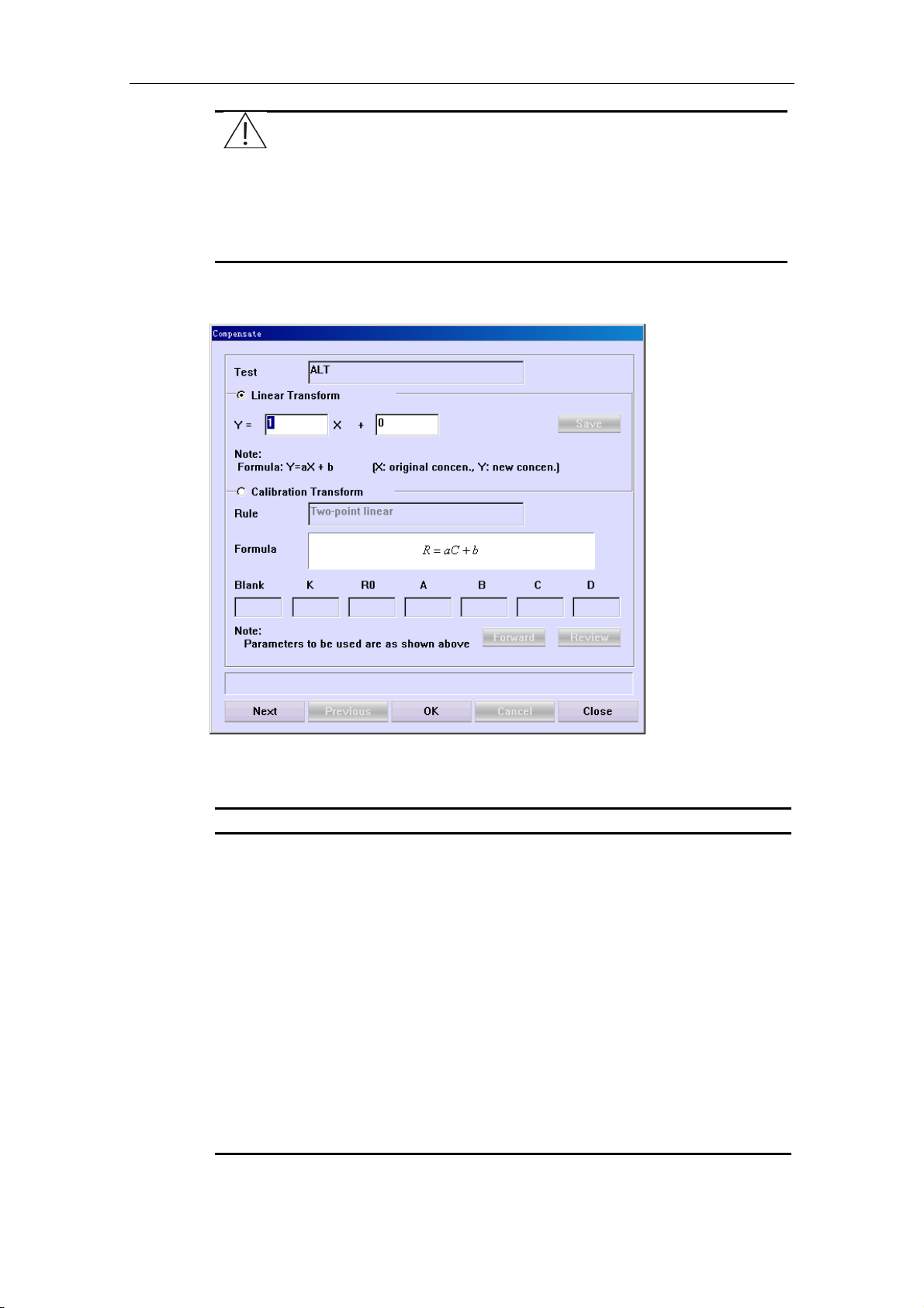
Advanced Operations
Figure 4-21 Compensate Dialog Box
NOTE:
Compensation is not available for calculation tests and off-system
tests.
If the compensated test is also a part of a calculation test, the analyzer
will automatically re-calculate the calculation test with the latest test
result.
The following table explains the parameters of the dialog box.
Parameter Description
Te st
Linear
Transform
Calibration
Transform
Name of the test, which means to transform the searched results
of this test.
Select to transform all searched results of the selected test in
linear way with the formula Y=aX+b.
Where,
X – The result before being transformed.
Y – The result after being transformed.
a, b – Coefficients of the linear transform, which can be entered
in the edit box.
Select to transform all searched results of the selected test
through calibration, which means to re-calculate the results with
the default calibration parameters.
4-24

Advanced Operations
Parameter Description
Rule
The calibration rule used to obtain the default calibration
parameters.
Formula
Blank
K
R0
A
B
C
D
The following table introduces the buttons of the dialog box.
Button Function
Save
Forward
The calibration formula used to obtain the default calibration
parameters.
Reagent blank.
Parameter K.
Parameter R0.
Parameter A.
Parameter B.
Parameter C.
Parameter D.
Click this button to save modification to the coefficients without
re-calculating the results.
Click this button to display the next SPLINE parameter. It is
available for the SPLINE method only.
Review
Next
Previous
OK
Cancel
Close
4.10.4 Edit Results
At the Results screen, after selecting a test that is finished or has no result or
selecting an off-system test, click Edit to pop up the Edit Result dialog box, as
shown in Figure 4-22, where you can edit result of the selected test.
Click this button to display the previous SPLINE parameter. It is
available for the SPLINE method only.
Click this button to select next test.
Click this button to select previous test.
Click this button to start transforming all searched results of the
selected test in linear way or through calibration.
Click this button to cancel the linear or calibration transform.
Click this button to close the Compensate dialog box.
4-25

Advanced Operations
Figure 4-22 Edit Result Dialog Box
The following table explains some parameters of the dialog box.
Parameter Description
Original Res.
Current Res.
Remark
Results
The following table introduces the buttons of the dialog box.
Button Function
Add
Previous
Next
Result of the test calculated by the system. It cannot be edited.
Default result of the test. If the test has not been edited, the
result is the original one; otherwise, the result is the latest one.
Remarks on the test.
Description of the test result.
Click this button to add the selected Results to Remark.
Click this button to display the previous test result for the current
sample.
Click this button to display the next test result for the current
sample.
OK
Cancel
Close
Click this button to save modification to the test result.
Click this button to cancel modification to the test result.
Click this button to exit the Edit Result dialog box.
4-26

Advanced Operations
4.10.5 Reaction Curve
At the Results screen, after selecting a test, click Reac. Curve to pop up the Reaction Curve dialog box, as shown in Figure 4-23, where you can view the
reaction curve of the test.
Figure 4-23 Reaction Curve Dialog Box
The following table introduces the buttons of the dialog box.
Button Function
Refresh
Reac. Data
Click this button to refresh the current reaction curve.
Click this button to pop up a dialog box to display the reaction
data of current curve.
4-27
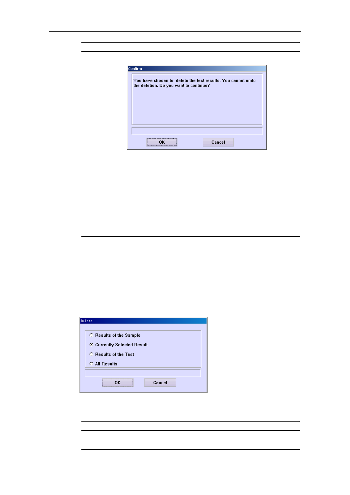
Advanced Operations
Button Function
Delete
Click this button to pop up the dialog box as shown below.
Click OK to delete the selected test, click Cancel to abort the
deletion.
Print
Previous
Next
Close
Click this button to print the current reaction curve.
Click this button to display the reaction curve of the previous test
for the current sample.
Click this button to display the reaction curve of the next test for
the current sample.
Click this button to close the Reaction Curve dialog box.
4.10.6 Delete Results
At the Results screen, after selecting a sample and a test, click Delete to pop up the
Delete dialog box, as shown in Figure 4-24, where you can delete relevant test
results.
Figure 4-24 Delete Dialog Box
The following table explains the parameters of the dialog box.
Parameter Description
Results of the
Sample
Delete all searched results of the selected sample.
4-28
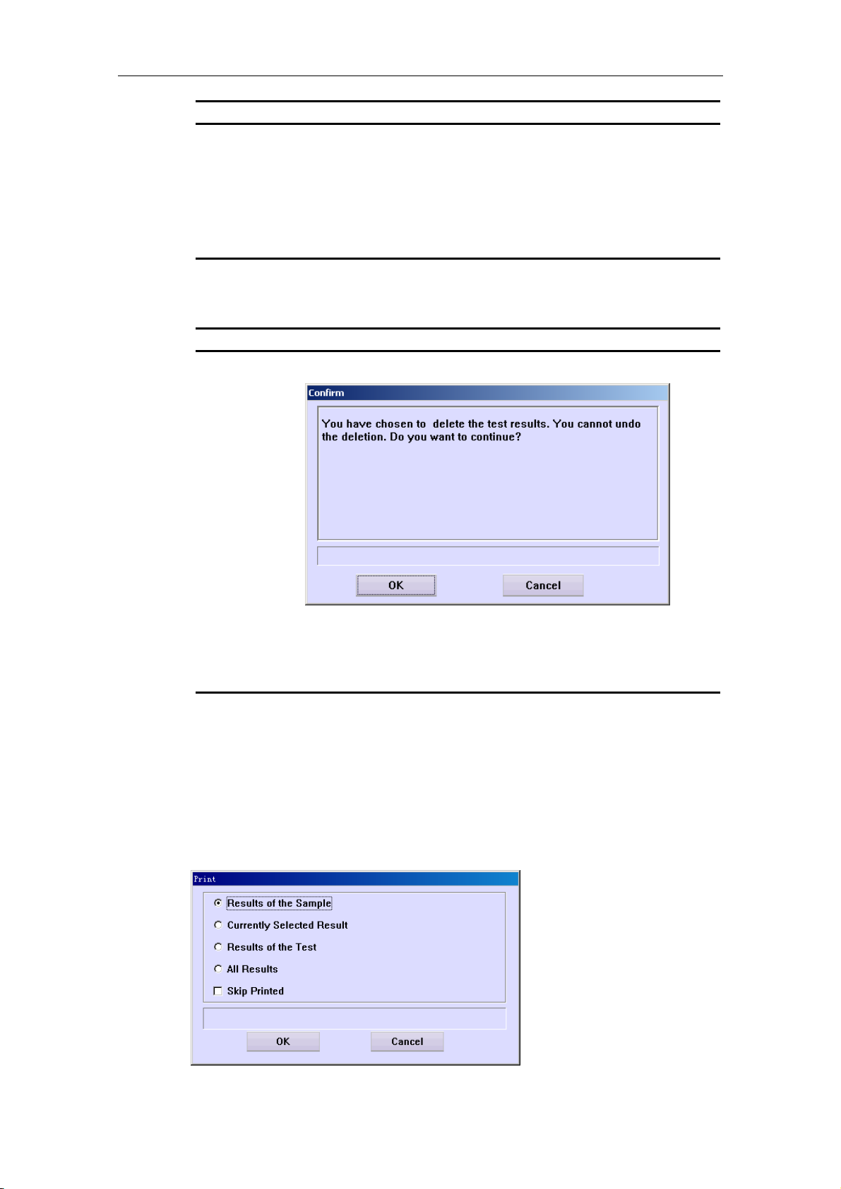
Advanced Operations
Parameter Description
Currently
Selected
Result
Delete the test result currently selected.
Results of the
Te st
All Results
The following table introduces the buttons of the dialog box.
Button Function
OK
Delete all searched results of the selected test.
Delete all results currently searched.
Click this button to pop up the following dialog box.
Cancel
4.10.7 Print Results
At the Results screen, after selecting a test, click Print to pop up the Print dialog
box, as shown in Figure 4-25, where you can print relevant results.
Figure 4-25 Print Dialog Box
Click OK to delete the specified result(s); click Cancel to abort
the deletion.
Click this button to cancel the deletion.
4-29

Advanced Operations
The following table explains the parameters of the dialog box.
Parameter Description
Results of the
Sample
Print all searched results of the selected sample.
Currently
Selected
Result
Results of the
Te st
All Results
Skip Printed
The following table introduces the buttons of the dialog box.
Button Function
OK
Cancel
Print the test result currently selected.
Print all searched results of the selected test.
Print all results currently searched.
Select to skip the results that have been printed.
Click this button to print the specified result(s).
Click this button to cancel printing.
4.10.8 Result Trend Curve
At the Results screen, after selecting (Organized by) Test and a test, click the Trend Curve button to pop up the Result Trend Curve, as shown in Figure 4-26,
where you can view the result trend curve of the selected test.
4-30
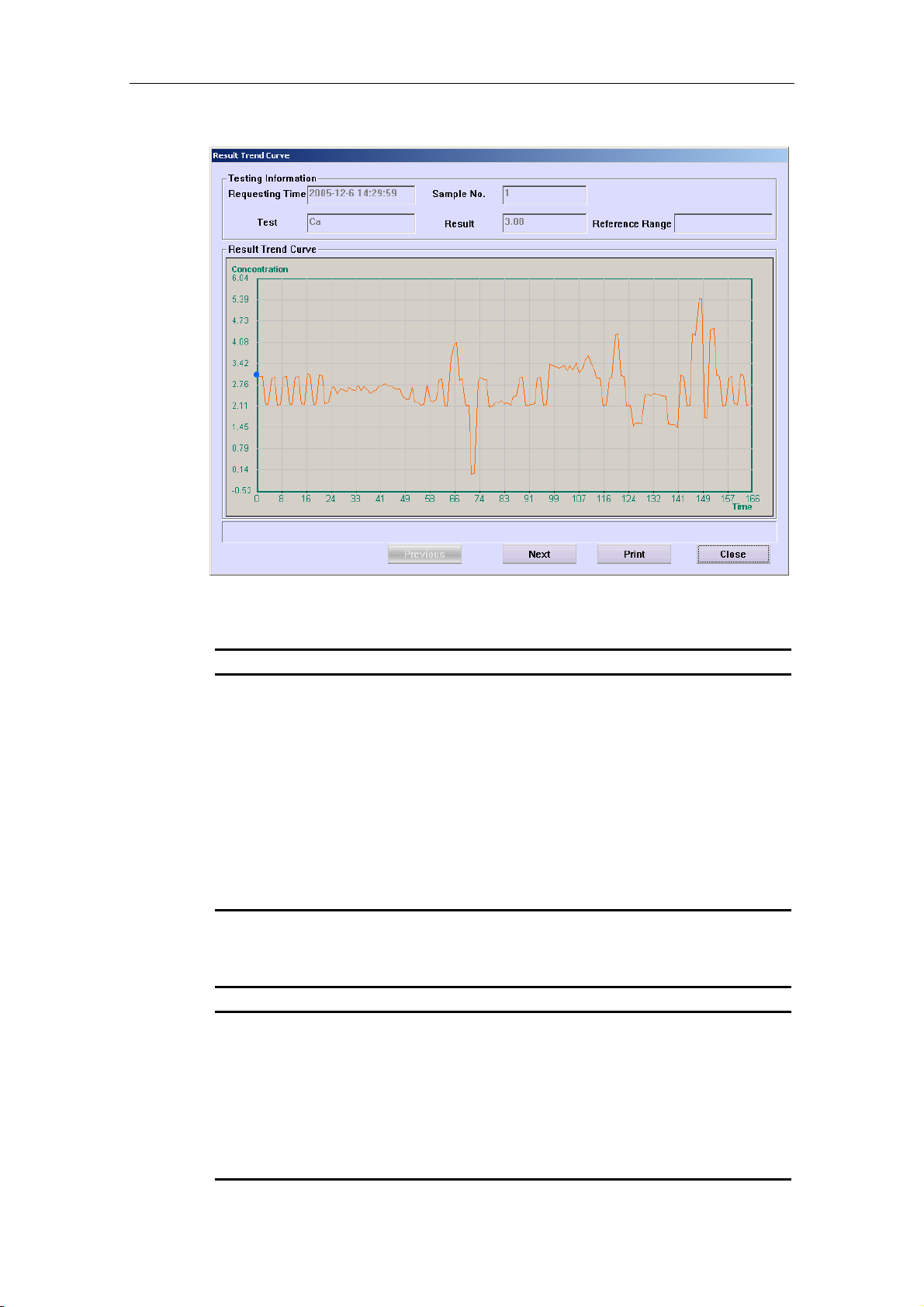
Advanced Operations
Figure 4-26 Result Trend Curve Screen
The following table explains the parameters of the dialog box.
Parameter Description
Requesting
Time
Sample No.
Te st
Result
Reference
Range
The following table introduces the buttons of the dialog box.
Button Function
Previous
The requesting time of the run which is corresponding to the blue
point on the result trend curve.
The sample No. of the run which is corresponding to the blue
point on the result trend curve.
The test that is corresponding to the result trend curve.
The result of the run that is corresponding to the blue point on
the result trend curve.
The reference range of the run that is corresponding to the blue
point on the result trend curve.
Click this button to display the testing information of the previous
run, which is corresponding to the blue point on the curve.
Next
Print
Close
Click this button to display the testing information of the next run,
which is corresponding to the blue point on the curve.
Click this button to print the current curve.
Click this button to close the Result Trend Curve dialog box.
4-31
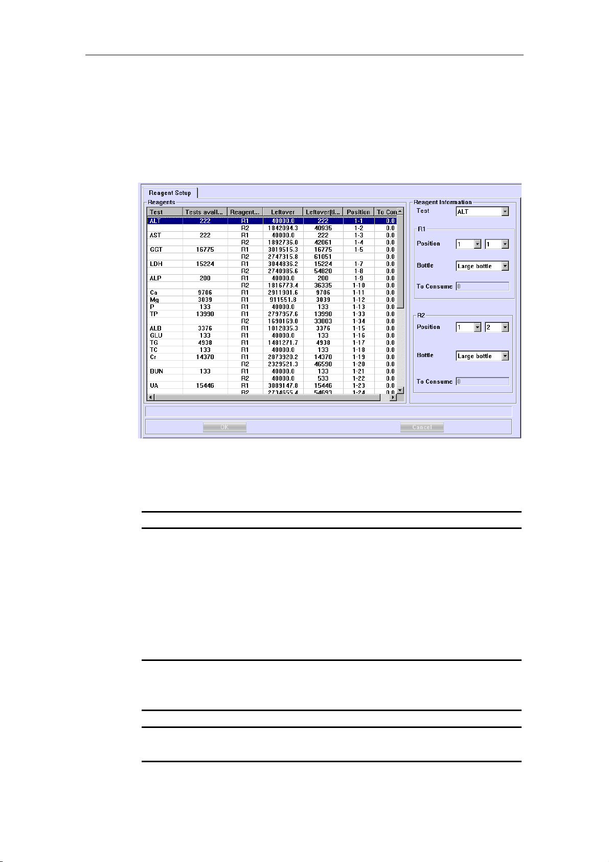
Advanced Operations
4.11 Reagent
Click Reagent to enter the Reagent Setup screen, as shown in Figure 4-27, where you can edit the reagent information.
Figure 4-27 Reagent Setup Screen
The Reagents list displays the reagent information of all tests.
The following table explains the parameters on the screen.
Parameter Description
Te st
Position
Bottle
To Consume
The following table introduces the buttons on the screen.
Button Function
OK
Select a test to edit the reagent information.
Position of the reagent bottle on the reagent disk.
The first drop-down list box is the No. of virtual reagent disk, and
the second is the position on the reagent disk.
Types of reagent bottle include Large bottle and Small bottle.
Estimated volume of the reagent to consume. The unit is µl. The
volume cannot be edited.
Click this button to save the reagent information set for the
selected test.
4-32
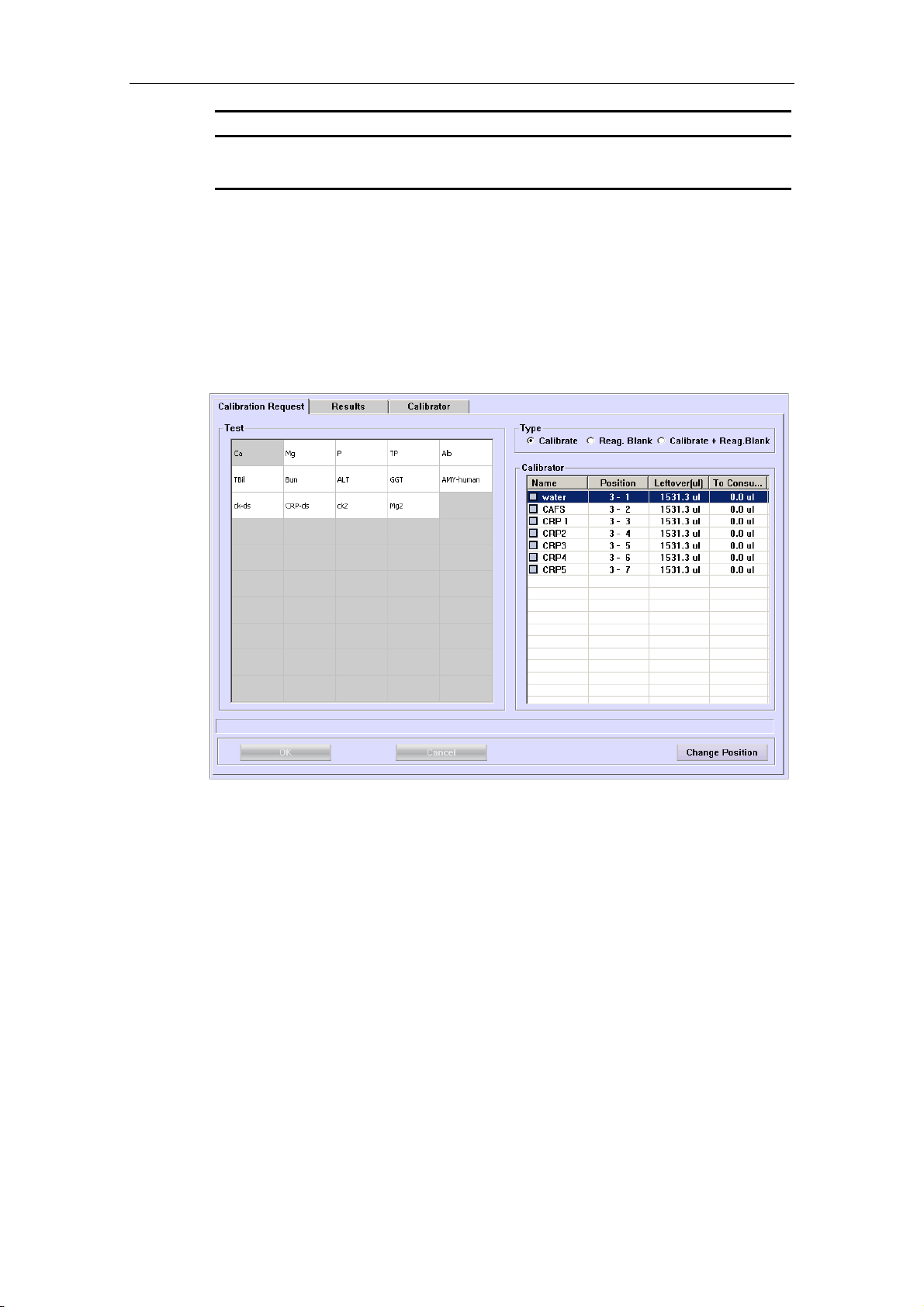
Advanced Operations
Button Function
Cancel
Click this button to cancel the reagent information set for the
selected test.
4.12 Calibration
Click Calibration to enter the screen as shown in Figure 4-28, where you can request calibration, view calibration results and set calibrator information.
Figure 4-28 Calibration Screen
The following sections introduce the Calibration screen by tab.
4.12.1 Calibration Request
The Calibration Request screen, as shown in Figure 4-29, is where you can request calibration.
4-33

Advanced Operations
Figure 4-29 Calibration Request Screen
CAUTION:
You need to run the calibration again when you change reagent lots,
test parameters, lamp or other analysis conditions.
The reagent blank is vital to obtaining correct analysis results. The
blank results can assist in determining whether the reagents have
expired, or whether the reaction background should be deducted, and
in eliminating the absorbance changes caused by the reagents
themselves. Mindray recommends the reagent blank be run on a daily
base.
The analyzer will use the result of the previous reagent blank run for
double-reagent tests that use endpoint method if no new reagent blank
result is available.
NOTE:
In the Tests field, different background colors of the test refer to
different meanings:
Blue means the test is selected;
White means the test is selectable;
Gray means the test is unselectable, and if the pointer of the mouse is
stopped on it for a while, the system will remind you of the reason why
it is unselectable.
4-34

Advanced Operations
The following table introduces the buttons on the Calibration Request screen.
Button Function
OK
After selecting calibration tests, click this button to finish
requesting.
Refer to the following text To Request Calibration for specific
operations.
Cancel
Change
Position
After selecting calibration tests, click this button to cancel
requesting.
Refer to the following text To Request Calibration for specific
operations.
After selecting a calibrator in the Calibrator area, click this
button to pop up the Reset Position dialog box.
For more information about the Reset Position dialog box, refer
to the following text To Reset Position of a Calibrator.
To Request Calibration
1 Select a type in the Type area.
Where,
Calibraterefers to running calibration directly without testing the reagent
blank;
Reag. Blank refers to testing the reagent blank only.
Calibrate+Reag.Blank refers to testing the reagent blank and then
calibrating.
2 Select a test(s) in the Test list.
3 If you confirm to calibrate the selected tests, click OK; otherwise click
Cancel.
To Reset Position of a Calibrator
At the Calibration Request screen, after selecting a calibrator, click Change
Position to pop up the Reset Position dialog box, as shown in Figure 4-30, where
you can reset position of the selected calibrator on the sample disk.
4-35

Advanced Operations
Figure 4-30 Reset Position Dialog Box
The following table explains the parameters of the dialog box.
Parameter Description
Current
Current position of the selected calibrator on the sample disk.
New
Disk
Position
The following table introduces the buttons of the dialog box.
Button Function
Probe Stop
OK
New position of the selected calibrator on the sample disk.
No. of virtual sample disk.
Void means that the selected calibrator is not on the sample disk.
Position of the calibrator on the selected virtual sample disk.
Void means that the selected calibrator is not on the sample disk.
If the system is in testing status, and the calibrator position to be
changed or the target position is on the sample disk currently
running, you should first stop the probe, the mixing bar and the
sample/reagent disk.
Click this button to stop the probe, the mixing bar, the
sample/reagent disk, and the button will change into Resume.
After exchanging the positions, click Resume to continue.
Click this button to save the new position you have set.
Cancel
Click this button to cancel the new position you have set.
CAUTION:
Do not put the probe, the mixing bar and the sample/reagent disk on
hold for a long time. Otherwise, certain analyses may be affected.
4-36

Advanced Operations
4.12.2 Results
The Results screen, as shown in Figure 4-31, is where you can view the calibration results.
Figure 4-31 Results Screen
In the View area, Current refers to the default calibration parameters of each test,
and History refers to all calibration results. The Test drop-down list box is only
available when History is selected.
NOTE:
This analyzer uses the default calibration parameters to calculate the
sample concentrations.
This analyzer will automatically set the latest parameters (including the
parameters obtained through calibration run, editing, calculation) as
the default.
The middle of the screen displays the tests, status and calibration parameters, etc.
An “!” showed on the left of the test name means that after you click the Test Data
button there is remark in the dialog box popped up.
The following table introduces the buttons on the screen.
4-37

Advanced Operations
Button Function
Calib. Curve
Click this button to pop up the Calibration Curve dialog box,
where you can view a calibration curve.
For more information about the Calibration Curve dialog box,
refer to the following text Calibration Curve.
Reac. Curve
Reag. Blk.
Tes t Da t a
Print
Default
Click this button to pop up the Calibration Reaction Curve
dialog box, where you can view a reaction curve.
For more information about the Calibration Reaction Curve
dialog box, refer to the following text Calibration Reaction
Curve.
After selecting a result, click this button to pop up the Reagent
Blank Trend Curve dialog box, where you can view the reagent
blank curve for the selected result.
For more information about the Reagent Blank Trend Curve
dialog box, refer to the following text Reagent Blank Trend
Curve.
After selecting a result, click this button to pop up the
Calibration Data dialog box, where you can view all the
calibration data of the selected result.
For more information about the Calibration Data dialog box,
refer to the following text Test Data.
Click this button to print the list in the middle of the Results
screen.
This button is available only when History is selected in the
View area.
Delete
Click this button to set the selected calibration result as the
default calibration parameters of this test.
After selecting a calibration result, click this button to pop up the
following dialog box.
Click OK to delete the selected calibration result or click Cancel
to abort the deletion.
4-38

Advanced Operations
Button Function
Re-run
This button is available only when Current is selected in the
View area.
After selecting a calibration result, click this button to re-request
calibration for the test and the current result is saved.
Calibration Curve
At the Results screen, click Calib. Curve to pop up the Calibration Curve dialog
box, as shown in Figure 4-32, which is used to display a calibration curve.
Figure 4-32 Calibration Curve Dialog Box
In the Calibration Curve dialog box, select a test in the Test drop-down list box to
view its calibration curve.
The following table introduces the buttons of the dialog box.
Button Function
Review
Forward
Click to view the parameters of the previous segment of SPLINE
calibration curve.
Click to view the parameters of the next segment of SPLINE
calibration curve.
4-39

Advanced Operations
Button Function
Range
Click this button to pop up the following dialog box, where you
can set the X/Y-coordinate ranges of the current calibration
curve.
Refresh
Print
Previous
Next
Close
Click this button to refresh the current calibration curve.
Click this button to print the current calibration curve.
Click this button to display the calibration curve of the previous
result.
Click this button to display the calibration curve of the next result.
Click this button to close the Calibration Curve dialog box.
Calibration Reaction Curve
At the Results screen, click Reac. Curve to pop up the Calibration Reaction
Curve dialog box, as shown in Figure 4-33, which is used to display a calibration
reaction curve.
4-40

Advanced Operations
Figure 4-33 Calibration Reaction Curve Dialog Box
In the Calibration Reaction Curve dialog box, after selecting a test in the Test
drop-down list box and a calibrator in the Calibrator drop-down list box, you can
view the reaction curve of the selected test with the selected calibrator.
The following table introduces the buttons of the dialog box.
Button Function
Refresh
Print
Previous
Next
Close
Click this button to refresh the current reaction curve.
Click this button to print the current reaction curve.
Click this button to display the reaction curve of current test with
the previous calibrator.
Click this button to display the reaction curve of current test with
the next calibrator.
Click this button to close the Calibration Reaction Curve dialog
box.
Reagent Blank Trend Curve
At the Results screen, click Reag. Blk to pop up the Reagent Blank Trend Curve
dialog box, as shown in Figure 4-34, which is used to display the reagent blank trend
curve of the selected calibration result.
4-41

Advanced Operations
Figure 4-34 Reagent Blank Trend Curve Dialog Box
The following table explains some parameters of the dialog box.
Parameter Description
View
The following table introduces the buttons of the dialog box.
Button Function
Refresh
Print
Previous
Next
There are two options as Measured and Estimated. The former
refers to displaying the measured values and the latter refers to
displaying the estimated values.
Click this button to refresh the current reagent blank trend curve.
Click this button to print the current reagent blank trend curve.
Click this button to display the reagent blank value of previous
point.
Click this button to display the reagent blank value of next point.
4-42

Advanced Operations
Button Function
Delete
Click this button to pop up the following dialog box.
Click OK to delete the reagent blank value of current point; click
Cancel to abort the deletion.
Close
Click this button to close the Reagent Blank Trend Curve dialog
box.
Test Data
At the Results screen, after selecting a calibration result, click Test Data to pop up
the Calibration Data dialog box, as shown in Figure 4-35, which is used to display
the calibration data of the selected result, and re-calculate or modify the calibration
parameters.
Figure 4-35 Calibration Data Dialog Box
The following table introduces the buttons of the dialog box.
4-43
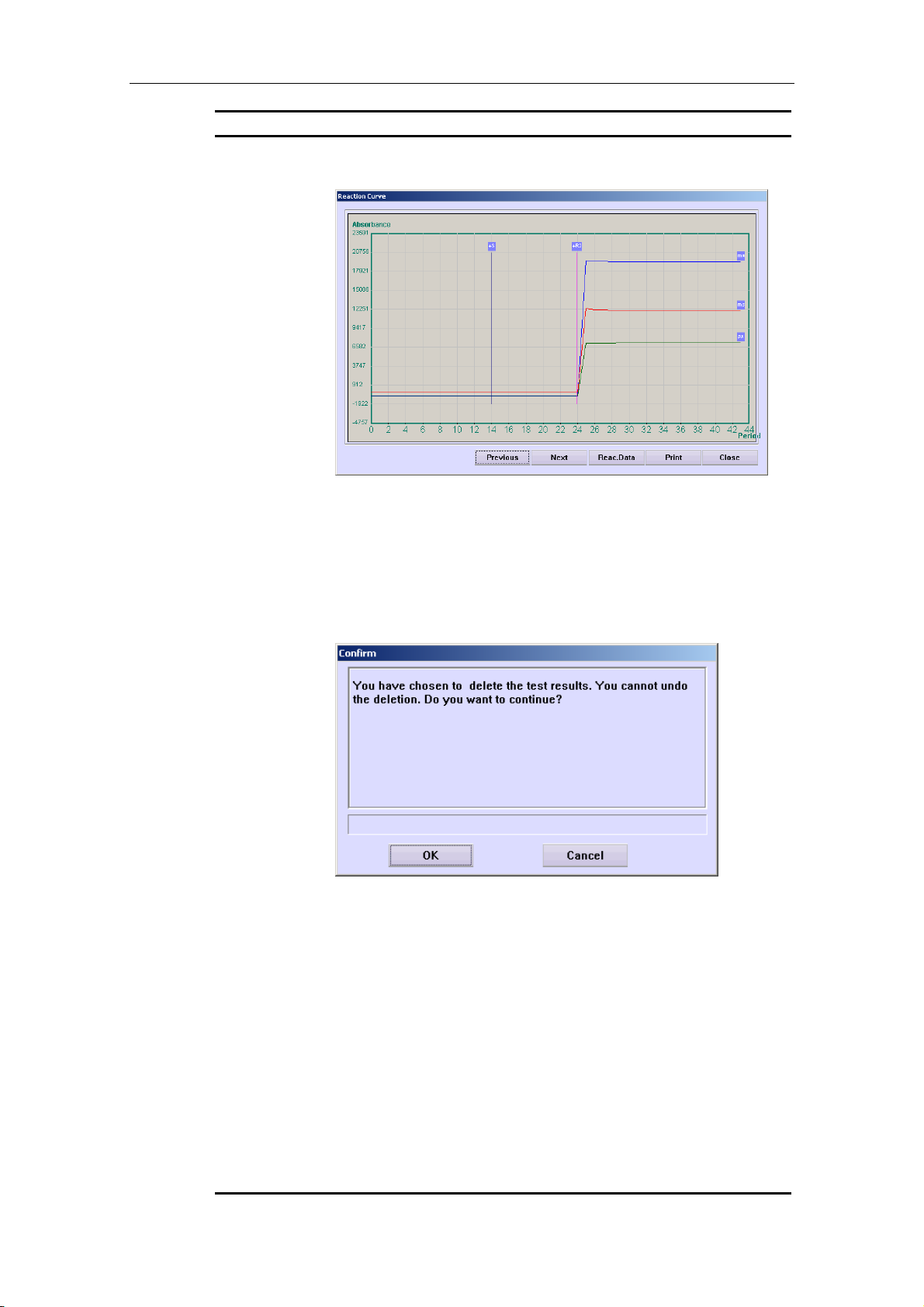
Advanced Operations
Button Function
Reac. Curve
Click this button to pop up the Reaction Curve dialog box as
shown below.
In the Reaction Curve dialog box, click Previous or Next to
display the previous or the next reaction curve; click Reac. Data
to pop up a dialog box to display the reaction data of the curve;
click Print to print current reaction curve; click Close to close the
Reaction Curve dialog box.
Delete
Re-run
Modify
After selecting a calibrator, click this button to pop up the
following dialog box.
Click OK to delete the selected test data; click Cancel to abort
the deletion.
Click this button to re-request the calibration test. This button is
only available for the calibration runs of current day since
powering on which have been finished or have no results.
Current calibration test data will be deleted.
Click this button to enable re-calculating or modifying calibration
parameters.
Re-calculate
After clicking the Modify button and selecting the calibrator and
calibration rule, click this button to re-calculate the parameters
with the new calibration rule.
You can modify the calibration parameters directly only after you
have re-calculated them successfully.
4-44

Advanced Operations
Button Function
OK
After successful re-calculation or calibration parameters
modification, click this button to save the change.
Refer to the following text To Re-calculate or Modify
Calibration Parameters for details.
Cancel
Close
After successful re-calculation or calibration parameters
modification, click this button to abort the change.
Refer to the following text To Re-calculate or Modify
Calibration Parameters for details.
Click this button to close the Calibration Data dialog box.
To Re-calculate or Modify Calibration Parameters
1 Click Modify.
2 Select a rule in the Rule drop-down list box.
3 Select test data according to the selected rule.
4 Click Re-calculate to re-calculate the calibration parameters with selected
rule and calibrators.
5 If you do not want to modify the calibration parameters after re-calculating,
go to step 7;
Otherwise, go directly to the next step.
6 Modify the parameters in the Parameters area.
7 Click OK to save the change; or click Cancel to ignore the change.
4.12.3 Calibrator
The Calibrator screen, as shown in Figure 4-36, is where you can set the basic information and concentration of calibrators.
4-45

Advanced Operations
Figure 4-36 Calibrator Screen
The following table explains the parameters on the screen.
Parameter Description
Name
Lot No.
Exp. date
Level
Position
Concen.
Name of the calibrator.
Lot No. of the calibrator.
The calibrator is effective before this date.
Concentration level of the calibrator. It includes High, Medium
and Low.
Position of the calibrator on the sample disk.
The first drop-down list box is the No. of virtual sample disk, and
the second is the position on the sample disk.
It refers to concentration of the selected calibrator for the
selected test.
NOTE:
Ensure the right expiration date is set so that the analyzer can correctly
judge whether the calibrator has expired.
The following table introduces the buttons on the screen.
Button Function
Add
Click this button to add new calibrators to the Calibrators list.
4-46
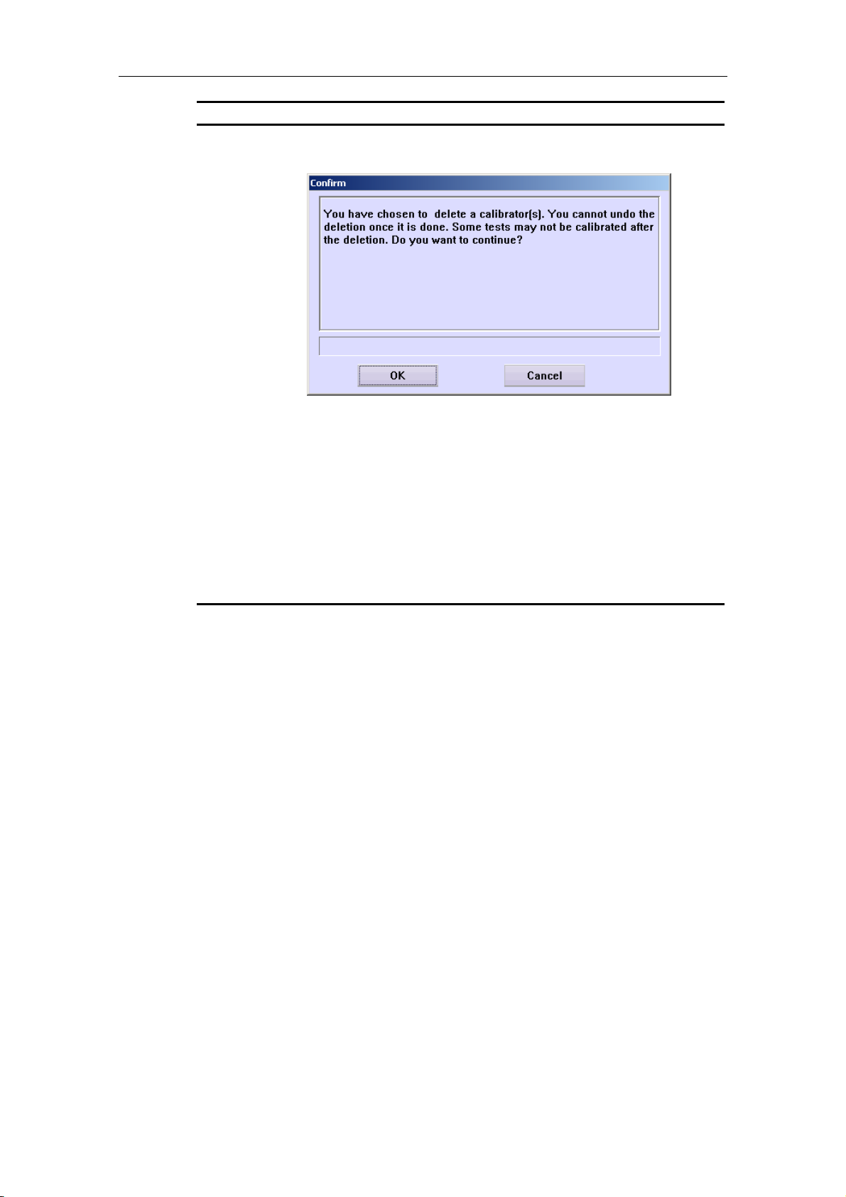
Advanced Operations
Button Function
Delete
After selecting a calibrator in the Calibrators list, click this button
to pop up the following dialog box.
Click OK to delete the selected calibrator; click Cancel to abort
the deletion.
OK
Cancel
Click this button to save modification to calibrator information.
Refer to the following text To Modify Calibrator Information for
detailed operations.
Click this button to cancel modification to calibrator information.
Refer to the following text To Modify Calibrator Information for
detailed operations.
To Modify Calibrator Information
1 Select a calibrator in the Calibrators list.
2 If you don’t need to modify the basic information of the selected calibrator,
proceed to the next step.
Otherwise, modify the basic information in the Calibrator Information area.
3 If you don’t need to modify the concentration of the selected calibrator,
proceed to the next step.
Otherwise, after selecting a test in the Tests list, enter concentration in the
Concen. edit box.
4 If you want to save the modification, click OK; otherwise click Cancel.
4.13 QC
Click QC to enter the screen as shown in Figure 4-37, which is used to display
results of real-time QC, daily QC and day-to-day QC and set controls.
4-47
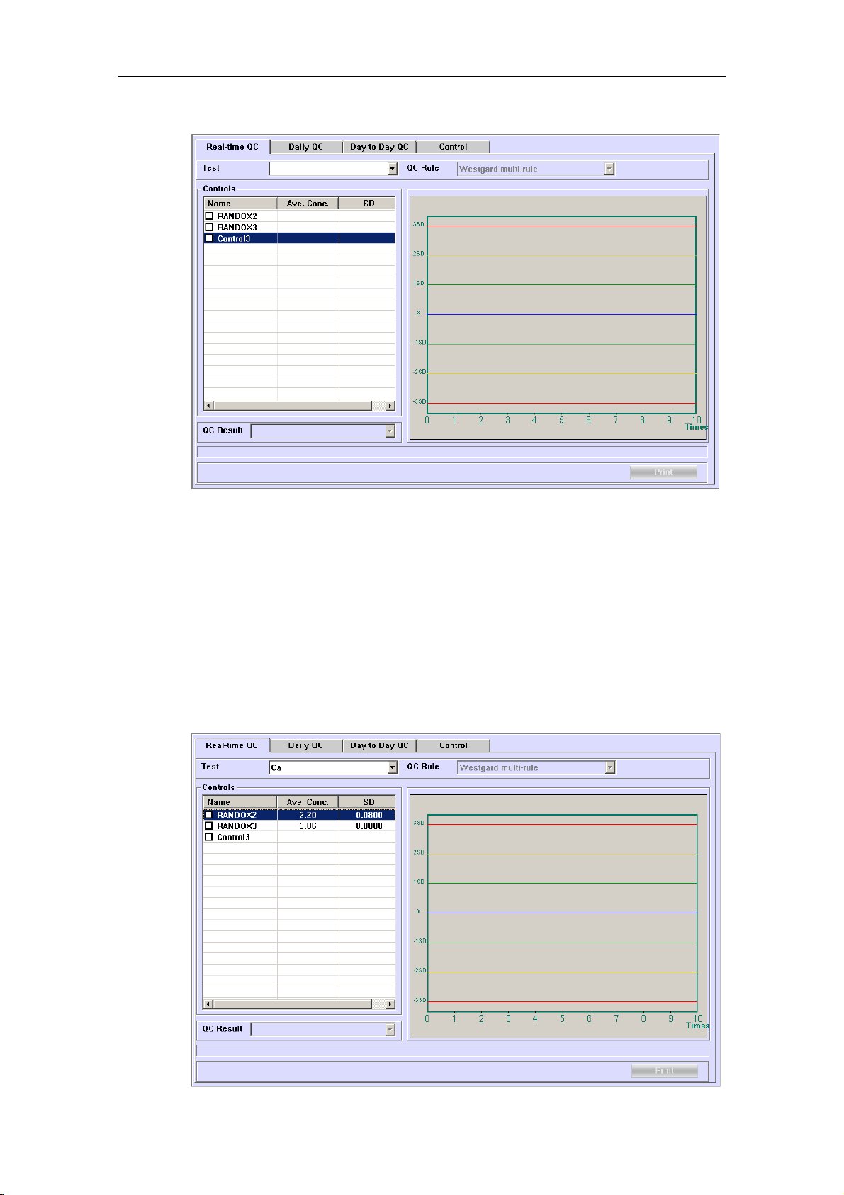
Advanced Operations
Figure 4-37 QC Screen
The following sections introduce the QC screen by tab.
4.13.1 Real-time QC
The Real-time QC screen, as shown in Figure 4-38, is used to display the Westgard Multi-rule QC plot for the recent 10 QCs of the current day.
Figure 4-38 Real-time QC Screen
4-48
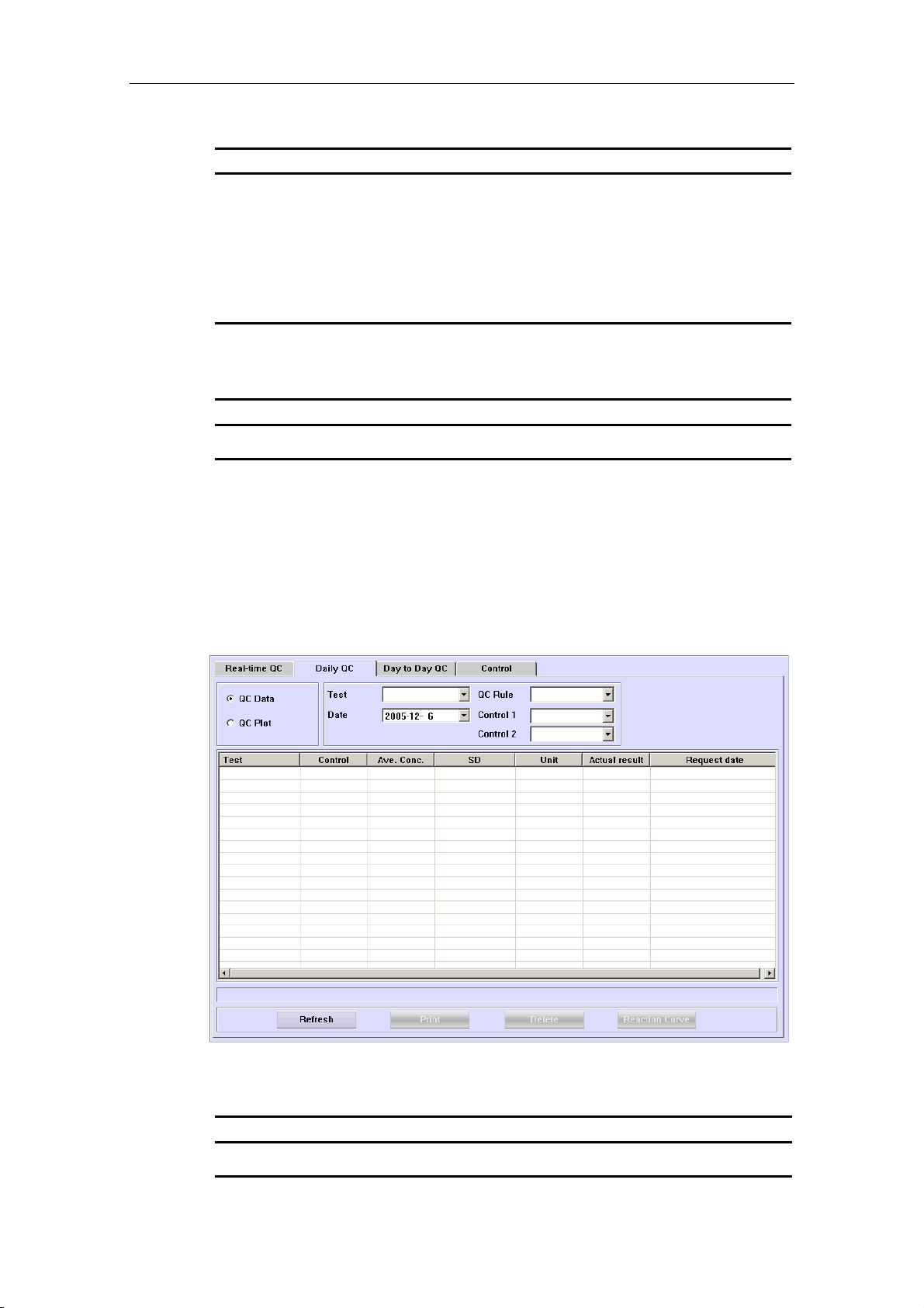
Advanced Operations
The following table explains the parameters on the screen.
Parameter Description
Te st
Select the test you need to view.
QC Rule
Controls
QC Result
The following table introduces the button on the screen.
Button Function
Print
4.13.2 Daily QC
The Daily QC screen, as shown in Figure 4-39, is used to display the QC results of the selected test within one day.
Figure 4-39 Daily QC Screen
It refers to the Westgard Multi-rule and cannot be edited.
It displays the calibrators, concentration levels and SDs of the
selected test.
It displays the QC result of the selected test.
Click this button to print the real-time QC plot currently displayed.
The following table explains the parameters on the screen.
Parameter Description
QC Data
Select to display QC data on the screen.
4-49

Advanced Operations
Parameter Description
QC Plot
Select to display QC plot on the screen.
Te st
Date
QC Rule
Control 1
Control 2
The following table introduces the buttons on the screen.
Button Function
Refresh
Select the test you need to view.
Select the testing date of the QC results that you need to view.
It includes Westgard multi-rule, Cumulative Sum Check and
TWIN-PLOT rule.
Select the first control.
Select the second control.
After setting or changing searching conditions, the system will
not refresh the searching results automatically. You need to click
this button to refresh and display the latest results.
Click this button to pop up the following dialog box.
Print
Click OK to display the latest searching results; click Cancel to
abort refreshing.
Click this button to print the QC data or QC plot currently
displayed.
4-50

Advanced Operations
Button Function
Delete
After selecting one of the searched QC results, click this button
to pop up the following dialog box.
Click OK to delete the selected result; click Cancel to abort the
deletion.
Reaction
Curve
After selecting a QC result, click this button to pop up the QC
Reaction Curve dialog box, which is used to display the reaction
curve of the selected QC result.
For more information about the QC Reaction Curve dialog box,
refer to the following text QC Reaction Curve.
QC Reaction Curve
At the Daily QC screen, after selecting a QC result, click Reaction Curve to pop up
the QC Reaction Curve dialog box, as shown in Figure 4-40, where you can view
the reaction curve of the selected QC result.
4-51

Advanced Operations
Figure 4-40 QC Reaction Curve Dialog Box
The following table introduces the buttons of the dialog box.
Button Function
Refresh
Re-run
Print
Reac. Data
Close
Click this button to refresh the current reaction curve.
Click this button to re-request the current QC run. It is only
available for the QC runs of current day since powering on which
have been finished or have no results.
Click this button to print the current reaction curve.
Click this button to pop up a dialog box to display the reaction
data of the curve.
Click this button to close the QC Reaction Curve dialog box.
4.13.3 Day to Day QC
The Day to Day QC screen, as shown in Figure 4-41, is used to display the QC results of the selected test among days.
4-52

Advanced Operations
Figure 4-41 Day to Day QC Screen
The following table explains the parameters on the screen.
Parameter Description
QC Data
QC Plot
Te st
Date
QC Rule
Control 1
Control 2
Select to display QC data on the screen.
Select to display QC plot on the screen.
Select the test you need to view.
Select the starting date and ending date of the QC results you
need to view.
The first drop-down box is starting date, and the second one is
the ending date.
It includes Westgard multi-rule, Cumulative Sum Check and
TWIN-PLOT rule.
Select the first control.
Select the second control.
4-53
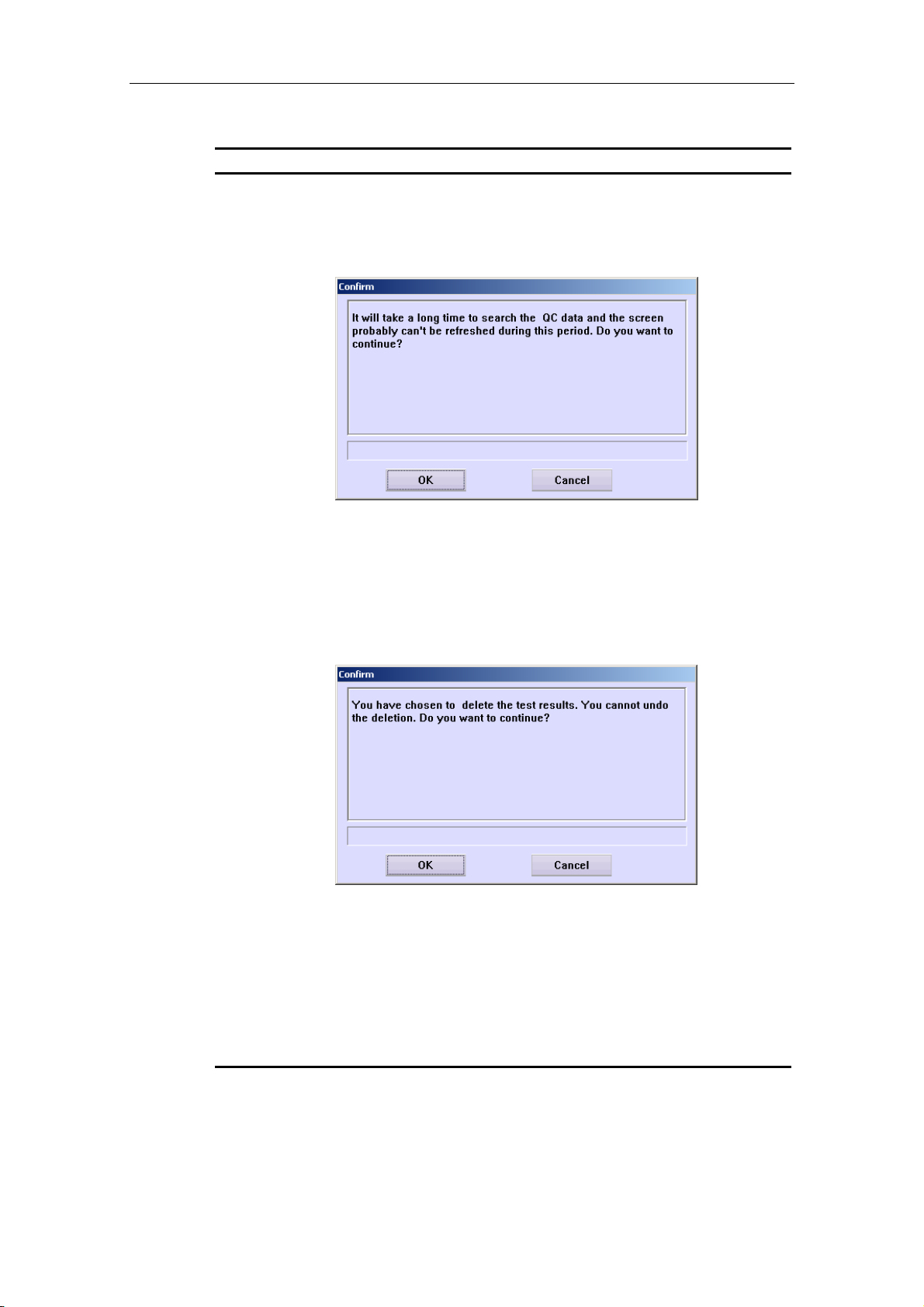
Advanced Operations
The following table introduces the buttons on the screen.
Button Function
Refresh
After setting or changing searching conditions, the system will
not refresh the searching results automatically. You need to click
this button to refresh and display the latest results.
Click this button to pop up the following dialog box.
Print
Delete
Reaction
Curve
Click OK to display the latest searching results; click Cancel to
abort refreshing.
Click this button to print the QC data or QC plot currently
displayed.
After selecting one of the searched QC results, click this button
to pop up the following dialog box.
Click OK to delete the selected result; click Cancel to abort the
deletion.
After selecting one of the searched QC results, click this button
to pop up the QC Reaction Curve dialog box, which is used to
display the reaction curve of the selected QC result.
For more information about the QC Reaction Curve dialog box,
refer to the following text QC Reaction Curve.
QC Reaction Curve
At the Day to Day QC screen, after selecting one of the searched QC results, click
Reaction Curve to pop up the QC Reaction Curve dialog box, as shown in Figure
4-42, where you can view the reaction curve of the selected QC result.
4-54
 Loading...