


Mindray DPM6 User manual

DPM 6 Patient Monitor
Service Manual


Intellectual Property Statement
Mindray DS USA, Inc. (hereinafter called Mindray DS) owns the intellectual property rights
to this product and this manual. This manual may refer to information protected by
copyrights or patents and does not convey any license under the copyright or patent rights of
Mindray DS, nor the rights of others. Mindray DS does not assume any liability arising out of
any infringements of patents or other rights of third parties.
Mindray DS intends to maintain the contents of this manual as confidential information.
Disclosure of the information in this manual in any manner whatsoever without the written
permission of Mindray DS is strictly forbidden. Release, amendment, reproduction,
distribution, rent, adaptation and translation of this manual in any manner whatsoever without
the written permission of Mindray DS is strictly forbidden.
is a trademark or a registered trademark of Shenzhen Mindray
Bio-Medical Electronics Co., Ltd. All third-party trademarks that appear in this manual are
used solely for editorial purposes and are the property of their respective owners.
Contents of this manual are subject to changes without prior notice.
Revision History
This manual has a revision number. This revision number changes whenever the manual is
updated due to software or technical specification change. Contents of this manual are subject
to change without prior notice.
Revision number: 5.0
Release time: 2012-02
© 2009-2012 Mindray DS USA, Inc. All rights reserved.
I

FOR YOUR NOTES
II

Preface
Manual Purpose
This manual provides detailed information about the assembling, dissembling, testing and
troubleshooting of the equipment to support effective troubleshooting and repair. It is not
intended to be a comprehensive, in-depth explanation of the product architecture or technical
implementation. Observance of the manual is a prerequisite for proper equipment
maintenance and prevents equipment damage and personnel injury.
This manual is based on the maximum configuration; Therefore, some contents may not
apply to your monitor. If you have any question, please contact our Customer Service
Department.
Intended Audience
This manual is for biomedical engineers, authorized technicians or service representatives
responsible for troubleshooting, repairing and maintaining the patient monitors.
III

Abbreviations
Abbreviations used in this manual are:
MPM multi-parameter module
SMR satellite module rack
CMS central monitoring system
Passwords
A password may be required to access different modes within the monitor. The passwords are
listed below:
User maintenance: 888888
Factory maintenance: 332888
Demo mode: 2088
IV

Contents
1 Safety ................................................................................................................................. 1-1
1.1 Safety Information ..........................................................................................................1-1
1.1.1 DANGER ........................................................................................................... 1-2
1.1.2 Warnings............................................................................................................. 1-2
1.1.3 Cautions ............................................................................................................. 1-2
1.1.4 Notes .................................................................................................................. 1-3
1.2 Equipment Symbols ........................................................................................................ 1-3
2 Theory of Operation ........................................................................................................ 2-1
2.1 Introduction..................................................................................................................... 2-1
2.2 System Connections ........................................................................................................ 2-2
2.2.1 Mounting the Patient Monitor ............................................................................ 2-2
2.2.2 Connectors for Peripheral Devices..................................................................... 2-3
2.3 Main Unit ........................................................................................................................ 2-4
2.3.1 Input System ...................................................................................................... 2-5
2.3.2 Output System.................................................................................................... 2-6
2.3.3 Processing and Communications System........................................................... 2-8
2.3.4 Power Management System ............................................................................. 2-10
2.3.5 Equipment Interface System ............................................................................ 2-12
2.4 Parameter Module ......................................................................................................... 2-14
2.4.1 Module Infrared Communication Board .......................................................... 2-14
2.4.2 Module Power Board ....................................................................................... 2-14
2.4.3 Module Button Board....................................................................................... 2-14
2.4.4 Parameter Board............................................................................................... 2-14
2.5 SMR .............................................................................................................................. 2-15
3 Testing and Maintenance................................................................................................. 3-1
3.1 Introduction..................................................................................................................... 3-1
3.1.1 Test Equipment................................................................................................... 3-1
3.1.2 Test Report ......................................................................................................... 3-2
3.1.3 Preventative Maintenance .................................................................................. 3-2
3.1.4 Recommended Frequency .................................................................................. 3-2
3.2 Preventative Maintenance Procedures ............................................................................ 3-4
3.2.1 Visual Inspection................................................................................................ 3-4
3.2.2 NIBP Tests and Calibration ................................................................................ 3-5
3.2.3 Sidestream and Microstream CO
3.2.4 AG Tests ........................................................................................................... 3-10
3.2.5 Preventative maintenance test report................................................................ 3-13
Module Tests................................................ 3-8
2
1-1

3.3 Power On Test ...............................................................................................................3-14
3.4 Module Performance Tests............................................................................................ 3-15
3.4.1 ECG Tests and Calibration ............................................................................... 3-15
3.4.2 Resp Performance Test..................................................................................... 3-16
3.4.3 SpO
Test.......................................................................................................... 3-16
2
3.4.4 NIBP Tests........................................................................................................ 3-16
3.4.5 Temp Test ......................................................................................................... 3-17
3.4.6 IBP Tests........................................................................................................... 3-17
3.4.7 C.O. Test........................................................................................................... 3-19
3.4.8 Mainstream CO
3.4.9 Sidestream and Microstream CO
Tests...................................................................................... 3-20
2
Module Tests.............................................. 3-21
2
3.4.10 AG Tests ......................................................................................................... 3-21
3.4.11 ICG Test ......................................................................................................... 3-22
3.4.12 BIS Test .......................................................................................................... 3-22
3.4.13 RM Test .......................................................................................................... 3-23
3.4.14 CCO/SvO
Tests ............................................................................................. 3-24
2
3.5 Nurse Call Relay Performance Test .............................................................................. 3-25
3.6 Analog Output Performance Test .................................................................................. 3-25
3.7 Electrical Safety Test..................................................................................................... 3-26
3.8 Touchscreen Calibration................................................................................................ 3-26
3.9 Recorder Check............................................................................................................. 3-26
3.10 Network Print Test ...................................................................................................... 3-27
3.10.1 Equipment Connection and Setup .................................................................. 3-27
3.10.2 Print Function Test ......................................................................................... 3-27
3.11 Battery Check..............................................................................................................3-28
3.12 Factory Maintenance ................................................................................................... 3-29
3.12.1 Accessing Factory Maintenance Menu........................................................... 3-29
3.12.2 Drawing Waves .............................................................................................. 3-29
3.12.3 Recorder ......................................................................................................... 3-29
3.12.4 Software Version ............................................................................................ 3-30
3.12.5 Monitor Information....................................................................................... 3-31
3.12.6 Calibrate NIBP ............................................................................................... 3-31
4 Troubleshooting................................................................................................................ 4-1
4.1 Introduction..................................................................................................................... 4-1
4.2 Part Replacement ............................................................................................................4-1
4.3 Patient Monitor Status Check.......................................................................................... 4-1
4.4 Software Version Check.................................................................................................. 4-2
4.5 Technical Alarm Check ................................................................................................... 4-2
4.6 Troubleshooting Guide.................................................................................................... 4-2
4.6.1 Power On/Off Failures ....................................................................................... 4-2
4.6.2 Display Failures ................................................................................................. 4-3
4.6.3 Module Rack Failures ........................................................................................ 4-4
4.6.4 Alarm Problems.................................................................................................. 4-6
1-2

4.6.5 Button and Knob Failures .................................................................................. 4-7
4.6.6 Recorder Failures ............................................................................................... 4-7
4.6.7 Output Interface Failures.................................................................................... 4-8
4.6.8 CF Card Problems .............................................................................................. 4-8
4.6.9 Power Supply Failures ....................................................................................... 4-9
4.6.10 Network Related Problems............................................................................. 4-10
4.6.11 Software Upgrade Problems............................................................................4-11
4.6.12 Technical Alarm Messages ..............................................................................4-11
4.6.13 M51A Self Test Information............................................................................4-11
5 Repair and Disassembly .................................................................................................. 5-1
5.1 Tools................................................................................................................................ 5-1
5.2 Preparations for Disassembly.......................................................................................... 5-1
5.3 Disassembling Procedure ................................................................................................ 5-2
5.3.1 Removing the Recorder...................................................................................... 5-2
5.3.2 Separating the Front and Rear Housing ............................................................. 5-6
5.3.3 Removing the Power Switch & LED Board ...................................................... 5-8
5.3.4 Removing the Knob Encoder ............................................................................. 5-8
5.3.5 Removing the Button Board............................................................................... 5-9
5.3.6 Removing the Touchscreen Control Board ...................................................... 5-10
5.3.7 Removing the Inverter...................................................................................... 5-10
5.3.8 Removing the LCD ...........................................................................................5-11
5.3.9 Removing the Alarm LED Board..................................................................... 5-12
5.3.10 Removing the Fan Assembly.......................................................................... 5-13
5.3.11 Removing Battery Compartment Assembly................................................... 5-13
5.3.12 Removing the Integral Module Rack ............................................................. 5-14
5.3.13 Removing the CF Card Assembly.................................................................. 5-17
5.3.14 Removing the wireless AP assembly.............................................................. 5-18
5.3.15 Removing the Main Board ............................................................................. 5-20
5.3.16 Removing the Speaker ................................................................................... 5-22
5.3.17 Removing the Power Module Assembly ........................................................ 5-23
5.3.18 Removing the Main Support .......................................................................... 5-25
5.3.19 Removing the Interface Board Assembly....................................................... 5-25
5.4 Removing the SMR Assembly...................................................................................... 5-28
5.5 Disassembling Modules ................................................................................................ 5-32
5.5.1 Disassembling the ICG Module ....................................................................... 5-32
5.5.2 Disassembling CO
Module ............................................................................. 5-36
2
5.5.3 Disassembling the New MPM Module ............................................................ 5-42
6 Parts .................................................................................................................................. 6-1
6.1 Introduction..................................................................................................................... 6-1
6.2 Main Unit ........................................................................................................................ 6-2
6.2.1 Exploded View................................................................................................... 6-2
6.2.2 Parts List ............................................................................................................ 6-2
1-3

6.3 Front housing Assembly.................................................................................................. 6-3
6.3.1 12.1” LCD with Anti-glare Screen..................................................................... 6-3
6.3.2 12.1” LCD with Touchscreen............................................................................. 6-5
6.3.3 12.1” Screen Assembly (with anti-glare screen) ................................................ 6-7
6.3.4 12.1” Screen Assembly (with touchscreen)........................................................ 6-9
6.4 Main Unit ...................................................................................................................... 6-10
6.4.1 Main Unit Assembly ........................................................................................ 6-10
6.4.2 Battery Compartment Assembly ...................................................................... 6-12
6.4.3 Power Module assembly .................................................................................. 6-13
6.4.4 Interface Board Assembly ................................................................................ 6-14
6.4.5 Main Board Assembly...................................................................................... 6-17
6.4.6 Integral module rack ........................................................................................ 6-18
6.4.7 Main Support Assembly................................................................................... 6-19
6.4.8 Rear Housing Assembly................................................................................... 6-20
6.4.9 CF Card Assembly ........................................................................................... 6-21
6.4.10 6802 Internal Wireless AP Assembly ............................................................. 6-23
6.4.11 Recorder Assembly......................................................................................... 6-24
6.5 SMR .............................................................................................................................. 6-25
6.5.1 SMR Assembly................................................................................................. 6-25
6.5.2 SMR Inside Assembly...................................................................................... 6-26
6.6 Parameter Modules........................................................................................................ 6-27
6.6.1 MPM Module ................................................................................................... 6-27
6.6.2 New MPM Module .......................................................................................... 6-28
6.6.3 C.O. Module..................................................................................................... 6-30
6.6.4 RM Module ...................................................................................................... 6-32
6.6.5 ICG Module ..................................................................................................... 6-33
6.6.6 AG Module....................................................................................................... 6-35
6.6.7 BIS Module ...................................................................................................... 6-37
6.6.8 IBP Module ...................................................................................................... 6-39
6.6.9 Mindray CO
6.6.10 Oridion CO
Module....................................................................................... 6-40
2
Module ...................................................................................... 6-42
2
6.6.11 CCO Module .................................................................................................. 6-43
6.7 Remote Display Box ..................................................................................................... 6-45
6.8 Wireless AP................................................................................................................... 6-46
6.9 Replaceable Parts .......................................................................................................... 6-47
6.9.1 Main Unit ......................................................................................................... 6-47
SMR ........................................................................................................................ 6-49
6.9.2...........................................................................................................................6-49
6.9.3 New MPM Material ......................................................................................... 6-50
6.9.4 Parameter Modules........................................................................................... 6-52
7 Upgrade............................................................................................................................. 7-1
7.1 Introduction..................................................................................................................... 7-1
7.2 Upgrading Parameter Modules........................................................................................ 7-2
1-4

7.3 Upgrading Functional Assemblies .................................................................................. 7-5
7.3.1 Upgrading SMR ................................................................................................. 7-5
7.3.2 Upgrading Wireless Network Function.............................................................. 7-5
7.3.3 Upgrading Recorder ........................................................................................... 7-6
7.3.4 Upgrading Analog Output.................................................................................. 7-6
7.3.5 Upgrading CIS ................................................................................................... 7-6
7.4 Upgrading Software ........................................................................................................ 7-7
7.4.1 How to Upgrade Software.................................................................................. 7-8
A Electrical Safety Inspection ........................................................................................... A-1
A.1 Power Cord Plug ........................................................................................................... A-2
A.2 Device Enclosure and Accessories................................................................................ A-2
A.3 Device Labeling ............................................................................................................ A-3
A.4 Protective Earth Resistance ........................................................................................... A-3
A.5 Earth Leakage Test ........................................................................................................ A-5
A.6 Patient Leakage Current ................................................................................................ A-6
A.7 Mains on Applied Part Leakage .................................................................................... A-8
A.8 Patient Auxiliary Current .............................................................................................A-11
A.9 Functional test .............................................................................................................A-12
1-5

FOR YOUR NOTES
1-6
1 Safety
1.1 Safety Information
DANGER
z Indicates an imminent hazard that, if not avoided, will result in death or serious
injury.
WARNING
z Indicates a potential hazard or unsafe practice that, if not avoided, could result in
death or serious injury.
CAUTION
z Indicates a potential hazard or unsafe practice that, if not avoided, could result in
minor personal injury or product/property damage.
NOTE
z Provides application tips or other useful information to ensure that you get the
most from your product.
1-1

1.1.1 DANGER
There are no dangers that refer to the product in general. Specific “Danger” statements may
be given in the respective sections of this manual.
1.1.2 Warnings
WARNING
z All installation operations, expansions, changes, modifications and repairs of this
product are conducted by authorized personnel.
z There is high voltage inside the equipment. Never disassemble the equipment
before it is disconnected from the AC power source.
z When you disassemble/reassemble a parameter module, a patient leakage current
test must be performed before it is used again for monitoring.
z The equipment must be connected to a properly installed power outlet with
protective earth contacts only. If the installation does not provide for a protective
earth conductor, disconnect it from the power line and operate it on battery power,
if possible.
z Dispose of the package material, observing the applicable waste control regulations
and keeping it out of children’s reach.
1.1.3 Cautions
CAUTION
z Make sure that no electromagnetic radiation interferes with the performance of the
equipment when preparing to carry out performance tests. Mobile phone, X-ray
equipment or MRI devices are a possible source of interference as they may emit
higher levels of electromagnetic radiation.
z Before connecting the equipment to the power line, check that the voltage and
frequency ratings of the power line are the same as those indicated on the
equipment’s label or in this manual.
z Protect the equipment from damage caused by drop, impact, strong vibration or
other mechanical force during servicing.
1-2
1.1.4 Notes
NOTE
z Refer to Operation Manual for detailed operation and other information.
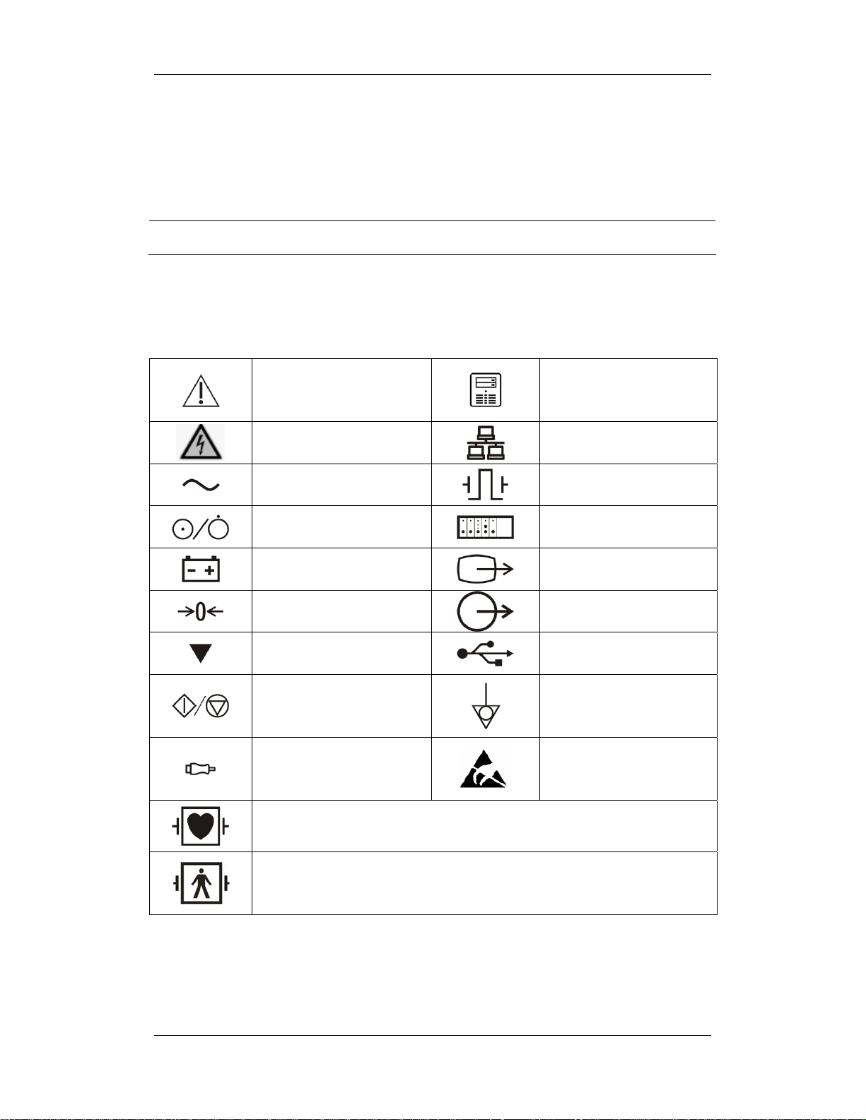
1.2 Equipment Symbols
Attention: Consult
accompanying documents
(this manual).
CIS connector
Danger: High-voltage
Alternating current(AC)
Power ON/OFF
Battery indication
Zero key
Calibrate key
Measure/Standby
Check sensor
Type CF applied part. Defibrillator-proof protection against electric shock.
Network connector
Defibrillator connector
Connector for satellite
module rack
Video output
Auxiliary output connector
USB connector
Equipotential terminal
ESD warning symbol for
Electrostatic sensitive
devices.
Type BF applied part. Defibrillator-proof protection against electric shock.
1-3

FOR YOUR NOTES
1-4

2 Theory of Operation
2.1 Introduction
This patient monitor is designed to monitor a fixed set of physiological parameters including
ECG, heart rate (HR), respiration (Resp), temperature (Temp), SpO
non-invasive blood pressure (NIBP), invasive blood pressure (IBP), cardiac output (C.O.),
carbon dioxide (CO
bispectral index (BIS) and respiration mechanics (RM) of single adult, pediatric and neonatal
patients
The patient monitor also:
Provides audible and visual alarm indications in case of patient or equipment problems.
), oxygen (O2), anesthetic gas (AG), impedance cardiograph (ICG),
2
, pulse rate (PR),
2
Enables displaying, reviewing, storing and transferring of real-time data.
Incorporates multiple input devices such as buttons, knob, touchscreen, keyboard and
mouse.
Interfaces a clinical information system or central monitoring system.
Enables program upgrade over the network.
2-1

2.2 System Connections
2.2.1 Mounting the Patient Monitor
The patient monitor can be mounted on a wall bracket or on a trolley support. The wall
bracket or trolley support can be ordered optionally. Each type of mounting bracket is
delivered with a complete set of mounting hardware and instructions. Refer to the
documentation delivered with the mounting hardware for instructions on assembling mounts.
CAUTION
z Use mounting brackets we supply or approve. If other compatible mounting
bracket is used, be sure it can be safely used on the patient monitor.
z The mounting bracket should be installed by our qualified service personnel, or
engineers who have adequate knowledge on it.
z If other mounting solution is used, the installation personnel and the customer
should verify if it can be safely used on the patient monitor, and the customer
assume the responsibility for any risk resulting from that.
2-2
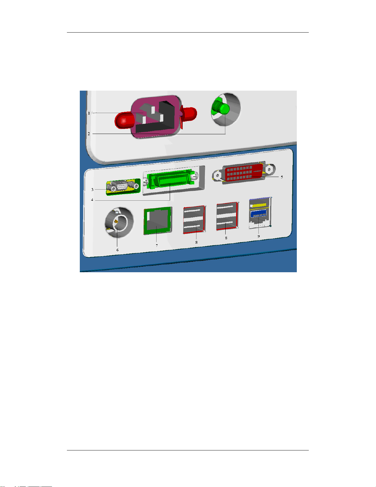
2.2.2 Connectors for Peripheral Devices
On the back of the patient monitor you will find all connectors for peripheral devices.
1. AC Power Connector: used to connect an AC power source (100 to 240 VAC, 50/60Hz).
2. Equipotential Terminal: used to connect the equipotential terminal of other equipment,
eliminating potential difference between different pieces of equipment.
3. Analog Output and Defibrillator Connector: It is a Micro-D connector used to output
analog signals and defibrillator synchronization signals.
4. CIS Connector: It is used to connect a CIS and output 12V DC power supply.
5. Video Output: It is a DVI-D connector used to connect a secondary display.
6. Auxi Output Connector: It is a BNC connector used to output nurse call signals.
7. Network Connector: It is a RJ45 connector used to connect an ethernet network or a PC.
8. USB Connector: used to connect any USB-compatible peripheral device.
9. SMR Connector: It is used to connect the SMR and outputs a 12V DC.
2-3
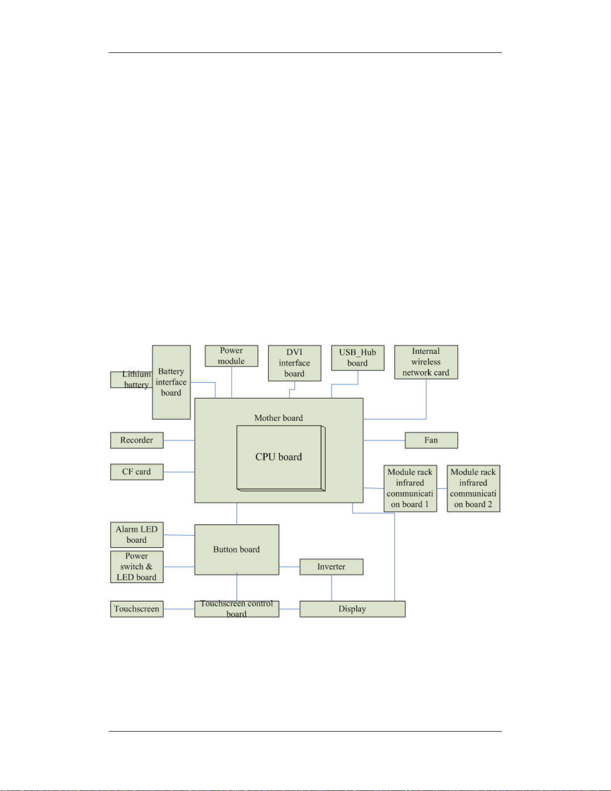
2.3 Main Unit
The patient monitor consists of:
Input system: button board, knob, touchscreen, power switch and LED board
Output system: LCD panel, alarm LED board, recorder and speaker
Processing and communications system: main board and integral module rack assembly.
Power management system: battery, battery interface board and power module
Equipment interface system: USB_Hub interface board, DVI interface board CF card
assembly and internal wireless network card.
Additionally, the patient monitor can also connect a satellite module rack (SMR), parameter
modules, mouse, keyboard, etc.
The following diagram illustrates the structure of the patient monitor
2-4
2.3.1 Input System
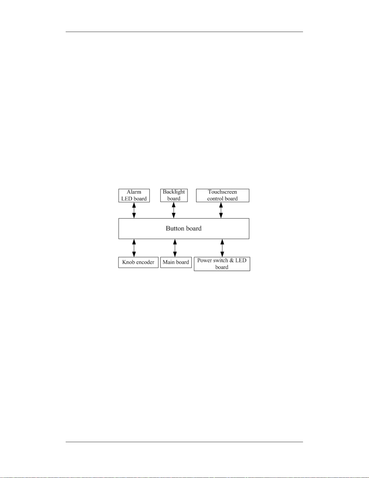
Button board
The button board, located at the lower part of the monitor’s front panel, contains 6 keys and
provides connections for the following components to the main board:
Knob
Power switch & LED board
Touchscreen control board
Alarm LED board
Inverter
The following diagram shows the button board connections.
Knob
The knob can be pressed, or rotated both clockwise and counter-clockwise. It is connected
with the button board.
Touchscreen
The touchscreen enables touch operations and can be calibrated. It is connected with the
touchscreen control board and main board.
Power switch & LED Board
The power switch & LED board controls the power supply for the main unit. It has three
LEDs, which respectively indicate the AC power status, battery status and monitor power
on/off status. It is connected with the button board.
2-5
2.3.2 Output System
LCD
The patient monitor adopts a high-resolution LCD. The LCD is connected with the main
board. The signals and power supply from the backlight board are transferred by the button
board.
Alarm Lamp
The patient monitor has two alarm lamps: alarm lamp and technical alarm lamp. Alarm lamp
lights either red or yellow whereas technical alarm lamp lights blue only. The alarm lamp
signals are transferred by the button board and are directly controlled by the main board
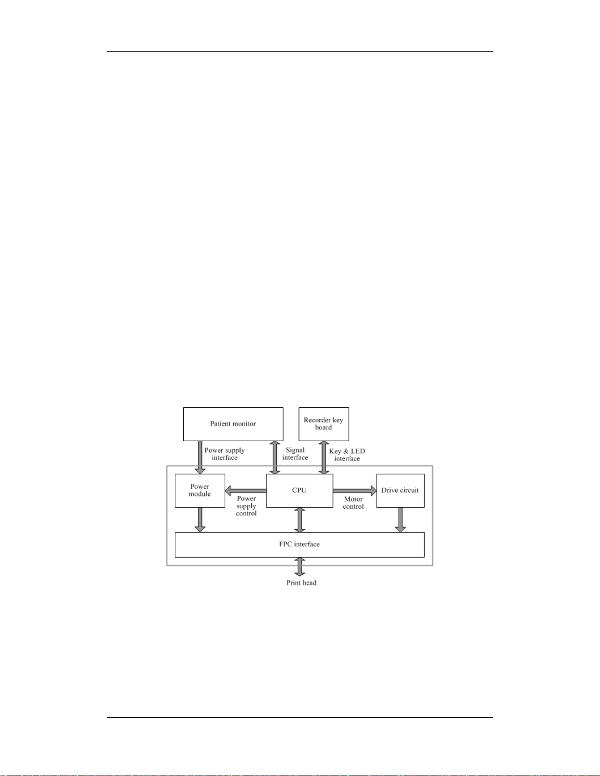
Recorder
The recorder receives data form the main board and then sends them to the thermal printhead
for printing. The recorder has a hardkey (starting/stopping recordings) and a green LED on its
front panel. It is connected with the mother board.
The following diagram shows its operating principle.
2-6

Module Description
Power interface Introduces a DC from the main board.
Recorder power
module
Recorder CPU Controls the communications between modules.
Signal interface
Motor drive circuit
Button & LED
board
Converts the input power into voltages that fit each module and then
forwards them to each module.
Controls the communications between the main board and the recorder
CPU.
Receives the control signals from the CPU and then forwards them to the
step motors
Includes one button and one LED which are directly controlled by the
CPU.
Speaker
The speaker provides sound for alarms, key strokes, heart beats and pulse, and allows PITCH
TONE and multi-level tone modulation. It is connected with the main board and is directly
driven by the main board.
2-7

2.3.3 Processing and Communications System
Main Board
The main board is the heart of the patient monitor. It implements a series of tasks including
input & output control, data storage and processing, display processing, system control,
communication management, printing management and alarming, etc.
The main board comprises the CPU board and mother board. The following diagram shows
interfaces to other components.
The CPU board is an essential CPU system containing the CPU, FLASH, memory, realtime
clock, EEPROM, etc. It interfaces to the mother board only, which then provides interfaces to
all other external devices.
2-8

The mother board is in charge of connections and communications with other components
and provides the following interfaces:
Name Description
LCD connector Connects the built-in display.
Video output +CIS+IO +IIC Connects the digital video interface board.
USB×2+network+RS422
+GPIO port
Button board connector Connects the button board.
Recorder connector Connects the recorder.
CF card connector Connects the CF card assembly.
Speaker connector Connects the speaker.
Power module connector Connects the power module.
Integral module rack connector
Fan connector Connects the fan.
CPU board It is connected with the mother board through a butt socket.
Internal wireless network card
assembly
Connects the USB_Hub board.
Connects the 3-slot rack communication board in the integral
module rack.
Connects the internal wireless network card.
Integral Module Rack
The patient monitor has two kinds of integral module rack: 2-slot and 5-slot. The control
board includes a NIOS II FPGA. It implements protocol conversion and infrared
communication between the main unit and the parameter modules
The module rack communication board can be a 2-slot type or a 3-slot type. The 3-slot
communication board communicates the main board directly. The 2-slot communication
board is connected with and controlled by the 3-slot communication board. The 3-slot
communication board has the function of communication control. The 2-slot communication
board consists of the infrared circuit and module power circuit. The RS422 drive circuit is
located on the 3-slot communication board.
2-9

2.3.4 Power Management System
Battery
The patient monitor uses two chargeable lithium-ion batteries (11.1 V, 4500 mAh). The
battery compartment is located at the bottom of the patient monitor. The battery power is
supplied to the mother board via the battery interface board, and then to the power module.
NOTE
z AC mains must be used when the CIS is connected with the patient monitor.
Battery Interface Board
The Battery interface board connects the batteries to the DC input terminal of the power
module via the mother board, implementing charging and discharging of the batteries and the
power board.
Power Module
The power module is located at the back of the patient monitor. The main part of the power
module is the power board, which contains charging & power management board, voltage
drop DC transforming board and voltage rise and drop DC transforming board.
The power module converts the input power into DC power supplies and then distributes
them to each component of the patient monitor. The input power comes from either the
batteries or an AC source. The patient monitor will run power from the AC source whenever
an AC source is available. If the AC source becomes unavailable, the patient monitor will
automatically switch to the battery power. This does not affect the monitor’s operating status.
The power module protects itself and the patient monitor by switching off AC input or DC
output in case of overcurrent, short circuit and overvoltage. The power module provides 3
DC outputs:
Outputs Description
+3.3 V
+5.0 V
Power supply of the LCD, mother board, CPU board, DVI interface
board and integral module rack.
Power supply of the DVI interface board, recorder, CF storage card
board and USB_Hub board.
+12 V
Power supply of the recorder, LCD inverter, integral module rack,
parameter modules, USB_Hub board and the CIS
2-10
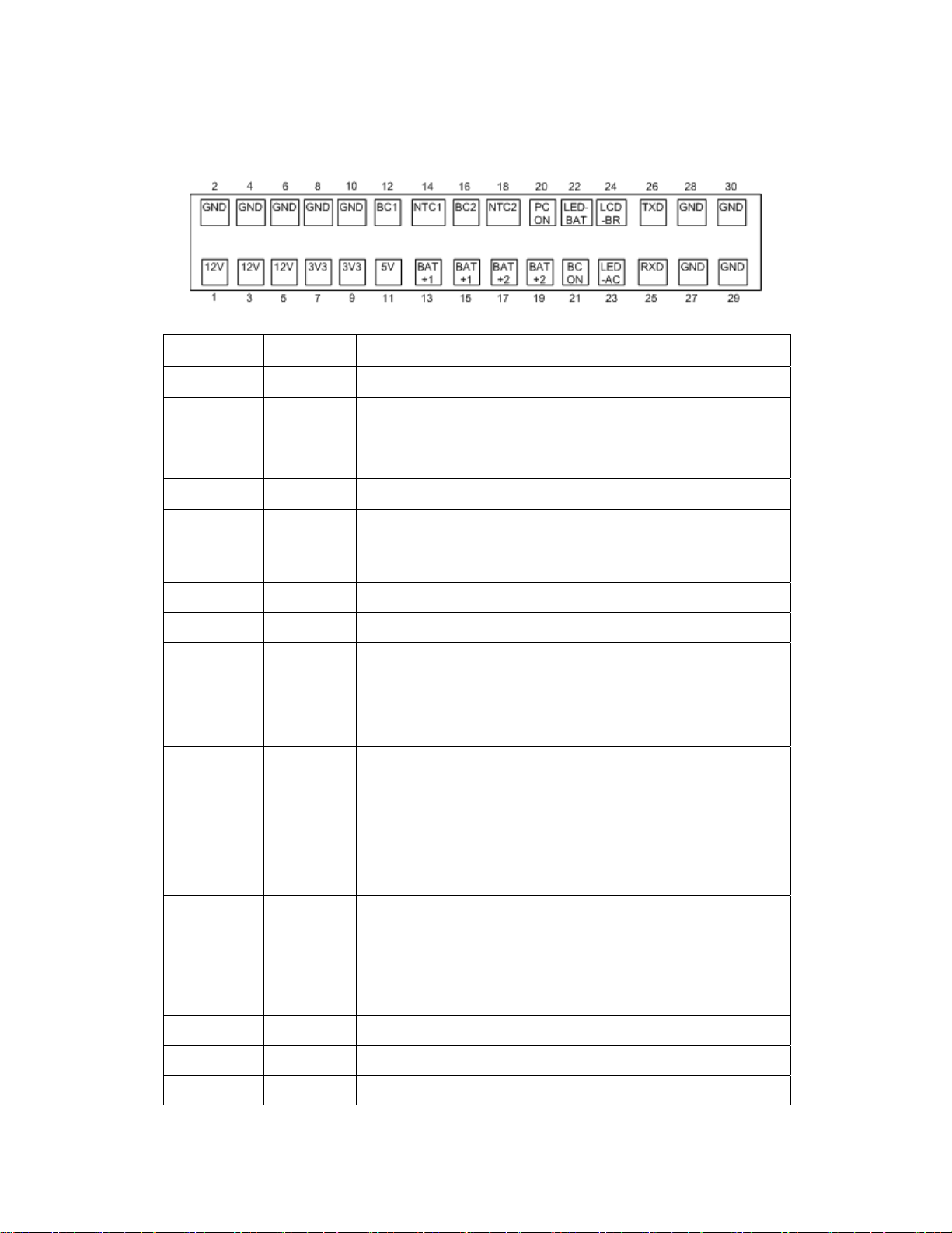
The following diagram shows the pins of the power socket connecting the power module and
the mother board:
Pin ID Marking Description
1/3/5 12V The positive output of the 12 VDC power
2/4/6/8/10/
GND The output grounding terminal of the power board.
27/28/29/30
7/9 3V3 The positive output of the 3.3 VDC power
11 5V The positive output of the 5 VDC power
12 BC1 Signal indicating whether battery 1 is available. Low level indicates
that battery 1 is available and high level indicates that battery 1 is
not available.
13/15 BAT+1 Input of battery 1, connecting to the positive pole of the battery.
14 NTC1 Thermistor signal of battery 1.
16 BC2 Signal indicating whether battery 2 is available. Low level indicates
that battery 2 is available and high level indicates that battery 2 is
not available.
18 NTC2 Thermistor signal of battery 2.
17/19 BAT+2 Input of battery 2, connecting to the positive pole of the battery.
20 PCON Power on/off control signal. It is a TTL pulse signal inputted from
the back board. Every time when the power on/off switch is pressed
(pulse of falling edge), a switch between power “on” and “off”
happens. The pulse duration is no less than 0.1 s for power on, 2 s
for power off and 10 s for illegal power off.
21 BCON Backlight on/off signal and switch output signal. The main board
sends the LCD backlight on/off signals to the power board via a
serial port, the power board processes the signals and output them.
Low level is output when the backlight is off and high level is
output when the backlight is on.
22 LED-BAT Battery status indication driving output
23 LED-AC AC power status indication signal
24 LCD-BR Backlight brightness control voltage.
2-11
2.3.5 Equipment Interface System
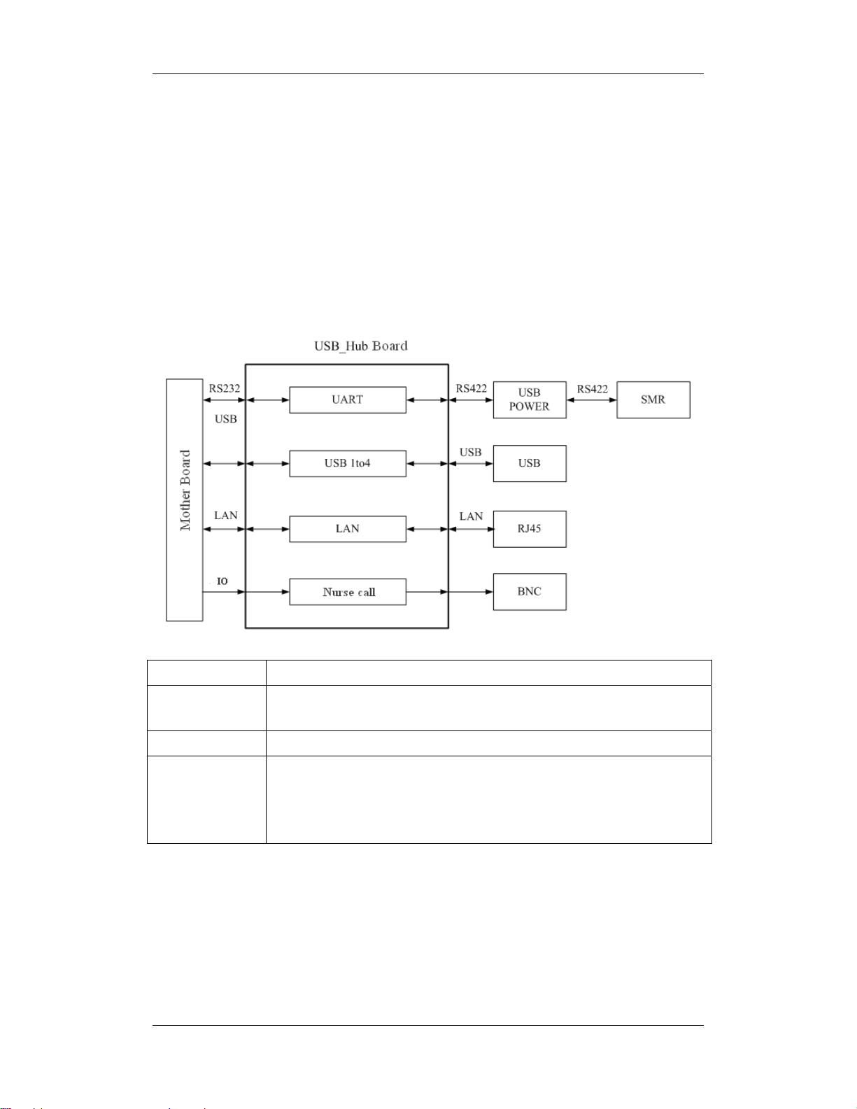
USB_Hub board
The USB_Hub board is connected with the mother board. It is compatible with USB1.1
connectors and supports equipment hot plug. The UART signal output by the main board is
converted into RS422 signal by the USB_HUB board. It receives 5 VDC and 12 VDC inputs
from the power module, of which the 5 VDC is supplied to the USB interface board and the
12 VDC is outputted to the SMR connector through a fuse.
BNC It is a BNC connector used to output nurse call signals.
RJ 45 connector
USB connector Connects devices with USB connector.
USB&POWER
connector
It is a standard RJ45 connector, providing 10/100 BASE-TX Ethernet
communications channels. It connects an Ethernet network or a PC.
Provides RS232 and RS422 interfaces for the communication between main
board and SMR. It receives 5 VDC and 12 VDC inputs from the power
module, of which the 5 VDC is supplied to the USB interface board and the
12 VDC is outputted to the SMR connector through a fuse.
2-12

DVI Interface Board
The DVI interface board is connected with the mother board. The following diagram shows
its interfaces to other components.
Interface Description
DVI connector Connects the secondary display.
CIS Connector Connects the CIS.
Micro-D connector Outputs analog signals and defibrillator synchronization signals.
CF Card Assembly
The CF assembly serves the non-volatile CF card which is used for data storage and
transferring. It is connected with the mother board.
Internal wireless network card
The internal wireless network card connects with the mother board. User can set network
type as LAN or WLAN through user interface and can set the internal wireless network card
through PC.
2-13

2.4 Parameter Module
Each parameter module may consist of the module infrared communication board, module
power board, module button board, parameter board, etc.
2.4.1 Module Infrared Communication Board
The module infrared communication board allows a short delay when powering up the
module and adopts FPGA to enable infrared communications between the module and the
module rack. An ID is integrated into the module infrared communication board. When a
module is inserted in the module rack, the ID is automatically sent to the module rack.
2.4.2 Module Power Board
Some modules have no power board. There are two kinds of module power board:
1. Isolated power board: converts the 12 V DC into a 12 V isolated DC and a 5 V isolated
DC.
2. Non-isolated power board: converts the 12 V DC into a 5 V DC
2.4.3 Module Button Board
There are keys and a LED on the module button board.
2.4.4 Parameter Board
The parameter board is a parameter measurement component, which is the most important
component of the parameter module.
2-14
 Loading...