


BC-5800
Auto Hematology Analyzer
Service Manual


Copyright
© 2008 Shenzhen Mindray Bio-medical Electronics Co., Ltd. All rights Reserved.
Intellectual Property Statement
SHENZHEN MINDRAY BIO-MEDICAL ELECTRONICS CO., LTD. (hereinafter called
Mindray) owns the intellectual property rights to this Mindray product and this manual. This
manual may refer to information protected by copyrights or patents and does not convey any
license under the patent rights of Mindray, nor the rights of others. Mindray does not assume
any liability arising out of any infringements of patents or other rights of third parties.
Mindray intends to maintain the contents of this manual as confidential information.
Disclosure of the information in this manual in any manner whatsoever without the written
permission of Mindray is strictly forbidden.
Release, amendment, reproduction, distribution, rent, adaption and translation of this manual
in any manner whatsoever without the written permission of Mindray is strictly forbidden.
, are the registered trademarks or trademarks owned by Mindray in China
and other countries. All other trademarks that appear in this manual are used only for editorial
purposes without the intention of improperly using them. They are the property of their
respective owners.
Responsibility on the Manufacturer Party
Contents of this manual are subject to changes without prior notice.
All information contained in this manual is believed to be correct. Mindray shall not be liable
for errors contained herein nor for incidental or consequential damages in connection with the
furnishing, performance, or use of this manual.
Mindray is responsible for safety, reliability and performance of this product only in the
condition that:
all installation operations, expansions, changes, modifications and repairs of this
product are conducted by Mindray authorized personnel;
the electrical installation of the relevant room complies with the applicable national
and local requirements;
the product is used in accordance with the instructions for use.
I
z
This equipment must be operated by skilled/trained medical professionals.
z
It is important for the hospital or organization that employs this equipment
to carry out a reasonable service/maintenance plan. Neglect of this may
result in machine breakdown or injury of human health.
z Be sure to operate the analyzer under the situation specified in this manual;
otherwise, the analyzer will not work normally and the analysis results will
be unreliable, which would damage the analyzer component s and cause
personal injury.
II

Warranty
THIS WARRANTY IS EXCLUSIVE AND IS IN LIEU OF ALL OTHER WARRANTIES,
EXPRESSED OR IMPLIED, INCLUDING WARRANTIES OF MERCHANTABILITY OR
FITNESS FOR ANY PARTICULAR PURPOSE.
Exemptions
Mindray's obligation or liability under this warranty does not include any transportation or
other charges or liability for direct, indirect or consequential damages or delay resulting from
the improper use or application of the product or the use of parts or accessories not approved
by Mindray or repairs by people other than Mindray authorized personnel.
This warranty shall not extend to:
any Mindray product which has been subjected to misuse, negligence or accident;
any Mindray product from which Mindray's original serial number tag or product
identification markings have been altered or removed;
any product of any other manufacturer.
Return Policy
Return Procedure
In the event that it becomes necessary to return this product or part of this product to Mindray,
the following procedure should be followed:
1. Obtain return authorization: Contact the Mindray Service Department and obtain a
Customer Service Authorization (Mindray) number. The Mindray number must
appear on the outside of the shipping container. Returned shipments will not be
accepted if the Mindray number is not clearly visible. Please provide the model
number, serial number, and a brief description of the reason for return;
2. Freight policy: The customer is responsible for freight charges when this product is
shipped to Mindray for service (this includes customs charges);
3. Return address: Please send the part(s) or equipment to the address offered by
Customer Service department.
III

Company Contact
Manufacturer: Shenzhen Mindray Bio-Medical Electronics Co., Ltd.
Address:
Phone:
Fax:
Mindray Building, Keji 12th Road South, Hi-tech Industrial Park,
Nanshan,ShenZhen 518057, P.R.China,
+86 755 26582479 26582888
+86 755 26582934 26582500
IV

Table of Contents
Copyright I
Warranty.............................................................................................................................III
Return Policy......................................................................................................................III
Table of Contents 1
1 Using This Manual 1-1
1.1 Introduction.......................................................................................................... 1-1
1.2 Who Should Read This Manual........................................................................... 1-2
1.3 How to Find Information ...................................................................................... 1-3
1.4 Conventions Used in This Manual....................................................................... 1-4
1.5 Special Terms Used in This Manual .................................................................... 1-5
1.6 Symbols............................................................................................................... 1-6
2 System Structure 2-1
2.1 System Overview................................................................................................. 2-1
2.2 Fluidic System ..................................................................................................... 2-2
2.3 Hardware System ................................................................................................ 2-3
2.4 Main Structure...................................................................................................... 2-4
2.5 Software Structure ............................................................................................. 2-12
3 Fluidic System 3-1
3.1 Introduction of Fluidic Parts................................................................................. 3-1
3.2 Introduction of Pneumatic Parts .......................................................................... 3-7
3.3 Fluidic System ..................................................................................................... 3-9
3.4 Basic Cycle Design Description......................................................................... 3-16
3.5 Sample Predilution Flowchart............................................................................ 3-25
4 Hardware System 4-1
4.1 Main Board .......................................................................................................... 4-3
4.2 Signal Processing Board ................................................................................... 4-21
4.3 Driver Board....................................................................................................... 4-36
4.4 Power Board ...................................................................................................... 4-75
4.5 Interface Board .................................................................................................. 4-84
4.6 Indicator Board .................................................................................................. 4-90
4.7 Touchscreen Control Board ............................................................................... 4-93
4.8 Pneumatic Control Board .................................................................................. 4-97
4.9 Pre-amplification Board, Laser Control Board and Volumetric Board ............. 4-103
4.10 Sample Transport Board.................................................................................. 4-122
4.11 Sample Detecting Board.................................................................................. 4-137
4.12 Pressure Detecting Board ............................................................................... 4-148
1

Using This Manual
4.13 SATA and IDE Signal Conversion Board......................................................... 4-154
5 Servicing 5-1
5.1 General ................................................................................................................ 5-1
5.2 Disassembling the Panels ................................................................................... 5-2
5.3 Replacing the Power Supply Assembly ............................................................. 5-12
5.4 Replacing the Touchscreen Assembly............................................................... 5-16
5.5 Replacing the Fluidic Components.................................................................... 5-22
5.6 Replacing the RBC Assembly............................................................................ 5-56
5.7 Replacing the HGB Bath Assembly ................................................................... 5-66
5.8 Replacing the WBC Bath Assembly .................................................................. 5-70
5.9 Replacing the Reagent Preheating Assembly ................................................... 5-76
5.10 Replacing the Open Vial Sampling/SRV Assembly........................................... 5-78
5.11 Replacing the Sample Transmitting Assembly .................................................. 5-96
5.12 Replacing the Autosampler and Mixer Assemblies ......................................... 5-115
5.13 Replacing the Pneumatic Unit ......................................................................... 5-130
5.14 Replacing the Ambient Temperature Sensor................................................... 5-138
5.15 Replacing the Blood Sensor ............................................................................ 5-140
5.16 Replacing the Filtering Cartridge ..................................................................... 5-142
6 Optical System 6-1
6.1 Optical System Adjustment and Servicing .......................................................... 6-1
6.2 Removing and Installing Optical System Assemblies.......................................... 6-2
6.3 Adjustment......................................................................................................... 6-11
6.4 Common Failures of the Optical System ........................................................... 6-27
7 Troubleshooting 7-1
7.1 Error code and information.................................................................................. 7-1
7.2 Causes of Common Errors .................................................................................. 7-6
7.3 Function Sequence Codes and Information ...................................................... 7-14
7.4 Error analysis and processing ........................................................................... 7-16
8 Maintaining Your Analyzer 8-1
8.1 List of Parts That Need to Be Replaced Periodically .......................................... 8-1
8.2 Basic Maintenance from Service Engineer ......................................................... 8-1
9 Appendices A-1
2
1 Using This Manual
1.1 Introduction
The chapter explains how to use the BC-5800 service manual. This manual provides the
reference information and procedures needed in servicing the BC-5800. Before servicing the
BC-5800, read and understand the manual carefully to ensure the proper servicing of the
equipment and personnel safety.
This manual is to be used together with the operation manual of BC-5800. It does not contain
information and procedures already covered in the operation manual of BC-5800.
z Be sure to operate and service the analyzer strictly as instructed in this
manual and the operation manual.
1-1

Using This Manual
1.2 Who Should Read This Manual
To use this manual effectively, you need to have the following capacities:
Comprehensive knowledge of electric circuit and fluidic system;
Comprehensive knowledge of reagents;
Comprehensive knowledge of quality control;
Thorough understanding of troubleshooting;
The ability to operate the analyzer skillfully;
The ability to use basic mechanical tools and understand related terminology;
The ability to use a digital voltmeter and an oscilloscope masterly;
And the ability to read pneumatic/hydraulic schematics and understand related
terminology.
1-2
Using This Manual
1.3 How to Find Information
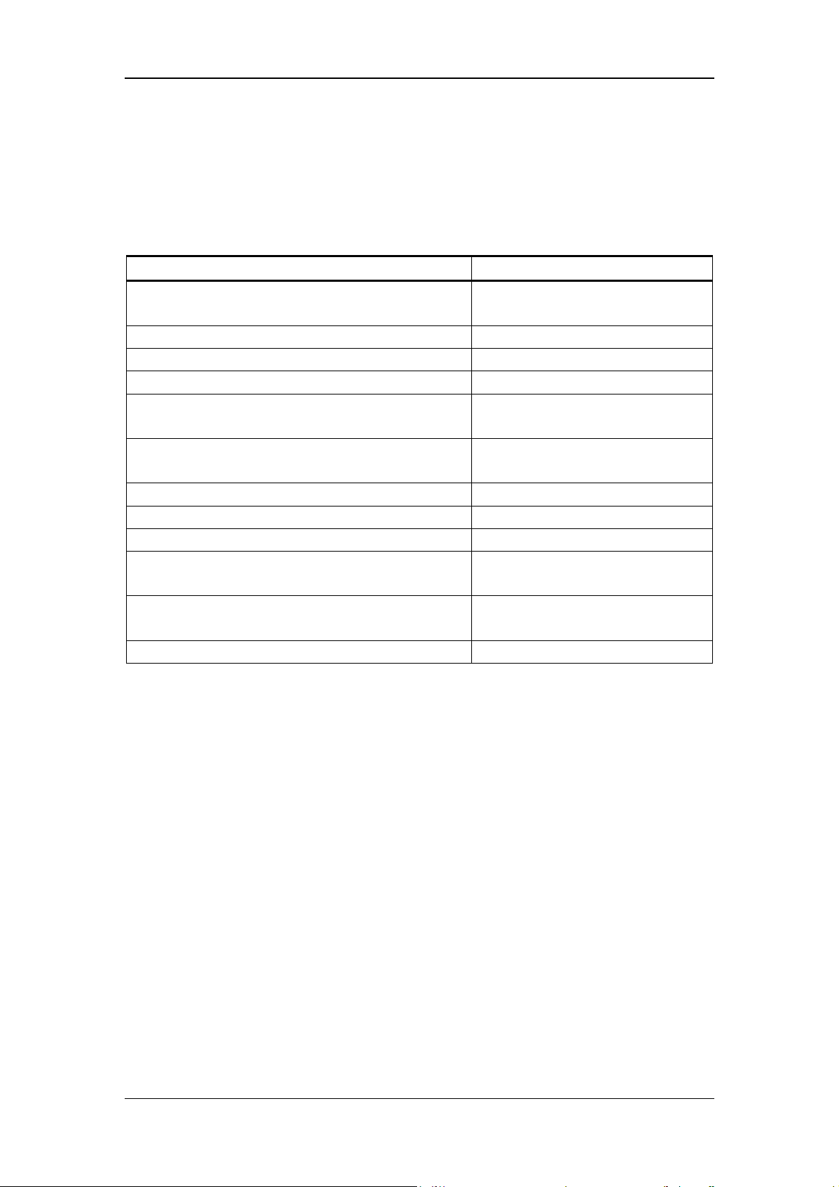
This operation manual comprises 8 chapters and 5 appendices. Refer to the table below to find
the information you need.
If you want to … See …
learn about the system structure and the basic
principle of BC-5800
learn about the fluidic system
learn about the hardware system
learn about how to service the BC-5800
learn about the optical system of BC-5800 and its
maintenance methods
learn about how to troubleshoot the common errors
of the BC-5800
learn about how to maintain the BC-5800
learn about the main spare parts of the BC-5800
learn about the main wearing parts of the BC-5800
learn about the schematic diagram of the fluidic
system of the BC-5800
learn about the function of each valve and pump of
the BC-5800
learn about the tubing connection of the BC-5800
Chapter 2 System Structure
Chapter 3 Fluidic System
Chapter 4 Hardware System
Chapter 5 Servicing
Chapter 6 Optical System
Chapter 7 T roubleshooting
Chapter 8 Maintenance
Appendix A List of Spare parts
Appendix B List of Wearing Parts
Appendix C Fluidic Diagram
Appendix D Pump and Valve
Function T a ble
Appendix E Tubing
1-3
Using This Manual
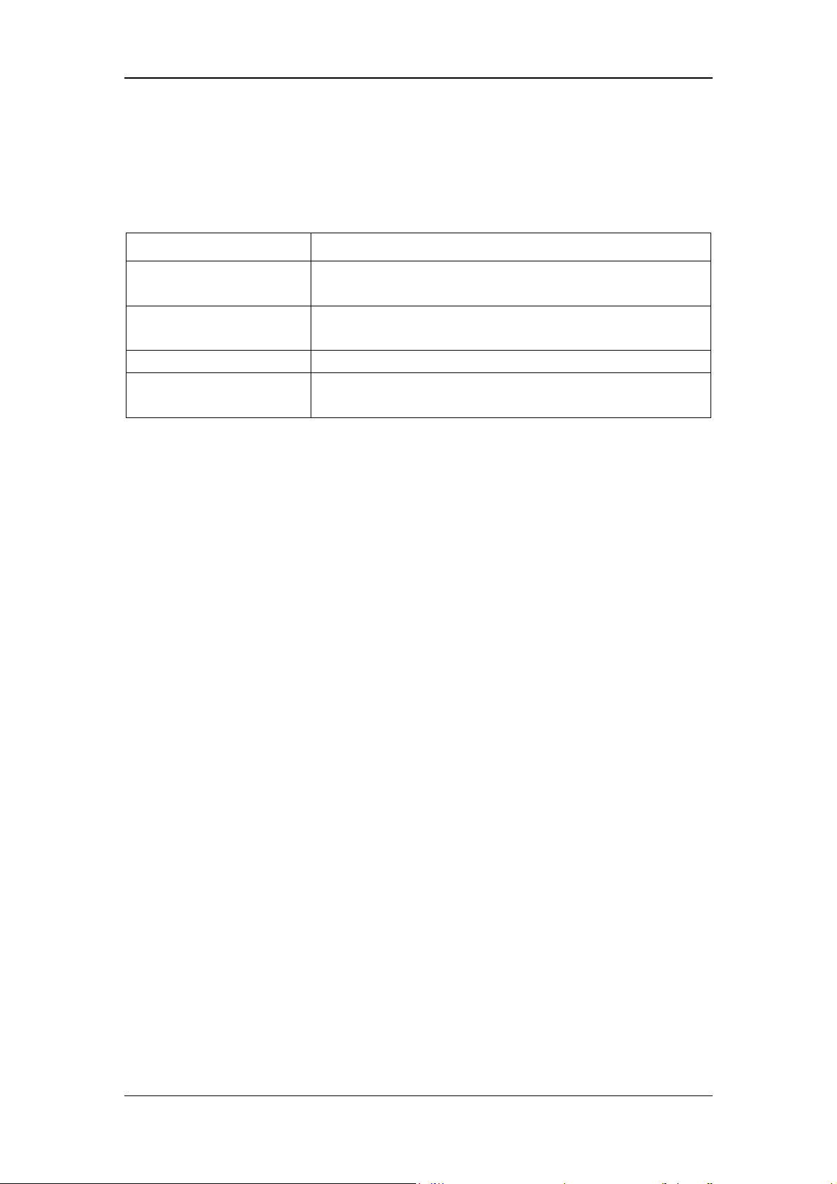
1.4 Conventions Used in This Manual
This manual uses certain typographical conventions to clarify meaning in the text:
Format Meaning
[XX] all capital letters enclosed in [ ] indicate a key name (either on
the pop-up keyboard or the external keyboard)
“XX” letters included in " " indicate text you can find on the screen
of BC-5800
XX italic letters indicate titles of the chapters that are referred to
XX
All illustrations in this manual are provided as examples only. They may not necessarily reflect
your analyzer setup or data displayed.
all-capitalized, bold and italic letters indicate a major operation
defined in Section 1.4
1-4

Using This Manual
1.5 Special Terms Used in This Manual
When you read … It means …
CLICK
ENTER
DELETE
DRAG SCROLL BAR
SELECT from
“ ** “ pull-down list
to press the desired item lightly with your finger; or to left-CLICK
it with the mouse.
to CLICK the desired edit box and use the external keyboard or
the pop-up keyboard to enter the desired characters or digits; or
to scan the number by using the bar-code scanner.
to move the cursor to the character or digit that you want to delete
by clicking the left button of the mouse or using
[←][→][Home][End],
and then delete the character after the cursor by pressing [Del], or
delete the character before the cursor by pressing [BackSpace]
([←] on the upper right part of the soft keyboard).
to CLICK the arrow buttons at the ends of the scroll bar; or to
CLICK and hold the mouse button down while dragging the scroll
bar until the desired information is displayed; or to touch the scroll
bar and rest your finger there until the desired information is
displayed.
to CLICK the down arrow button of the desired box to display the
pull-down list, (and DRAG SCROLL BAR) to browse and then
CLICK the desired item; or to press the keys
([↑][↓][PageUp][PageDown]) to browse the current list and press
[ENTER] to select the desired item.
1-5
Using This Manual
1.6 Symbols
You will find the following symbols in this manual.
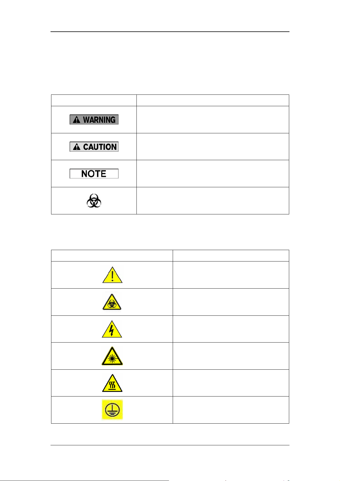
When you see… Then…
read the statement below the symbol. The statement is
alerting you to an operating hazard that can cause
personnel injury.
read the statement below the symbol. The statement is
alerting you to a possibility of analyzer damage or
unreliable analysis results.
read the statement below the symbol. The statement is
alerting you to information that requires your attention.
read the statement below the symbol. The statement is
You may find the following symbols on the analyzer, reagents, controls or calibrators.
When you see… It means…
alerting you to a potentially biohazardous condition.
CAUTION, CONSULT ACCOMPANYING
DOCUMENTS.
BIOLOGICAL RISK
HIGH VOLTAGE
WARNING, LASER BEAM
WARNING, HOT SURFACE
PROTECTIVE EARTH (GROUND)
1-6
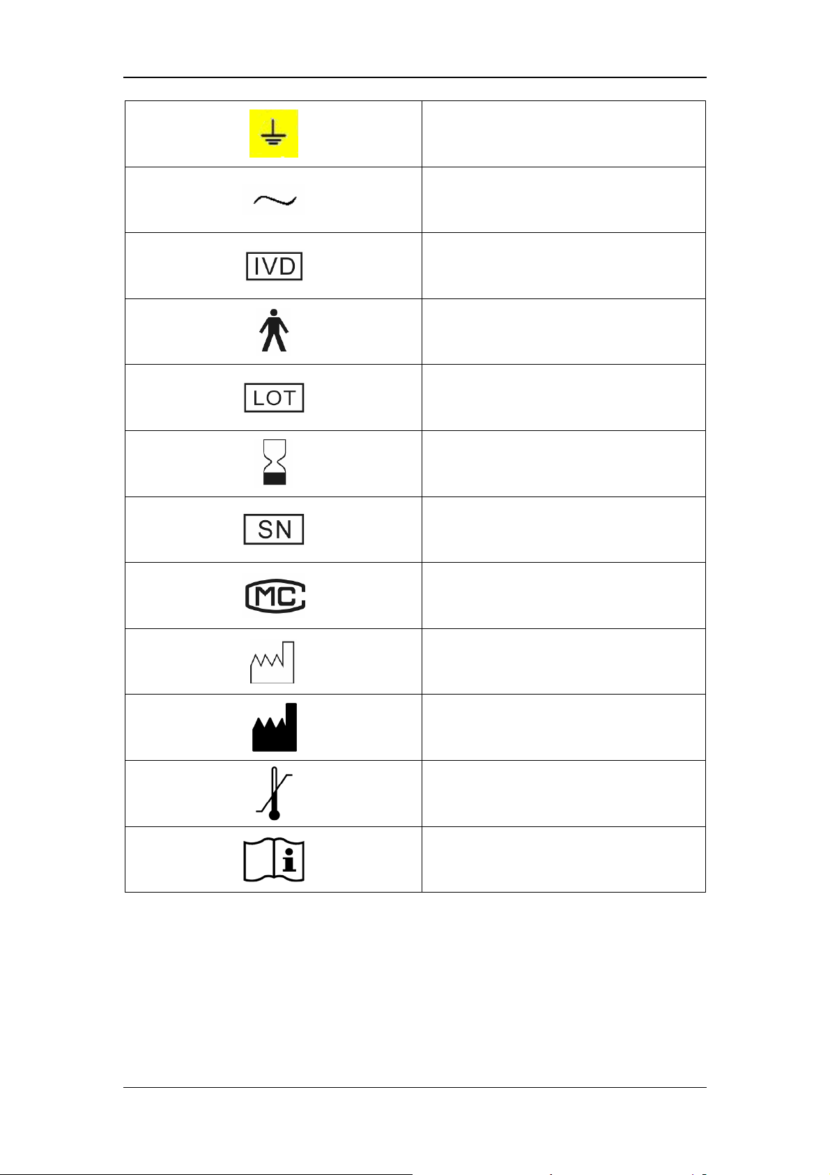
Using This Manual
EARTH (GROUND)
ALTERNATING CURRENT
FOR IN VITRO DIAGNOSTIC USE
TYPE B DEVICE
BATCH CODE
USE BY (YYYY-MM-DD)
SERIAL NUMBER
MEASUREMENT AUTHORIZATION
SYMBOL
DATE OF MANUFACTURE
MANUFACTURER
TEMPERATURE LIMITATION
CONSULT INSTRUCTIONS FOR USE
Be sure to observe the following precautions for the safety of patients, operators and yours
when you are servicing the analyzer.
1-7

Using This Manual
z It is important for the hospital or organization that employs this equipment
to carry out a reasonable service/maintenance plan. Neglect of this may
result in machine breakdown or harm to human health.
z Never use combustible gas (e.g. anesthetic) or combustible liquid (e.g.
ethanol) around the analyzer. Otherwise, the risk of explosion may exist.
z When servicing the analyzer, be sure to turn off the power. Servicing the
analyzer when it is on may bring risk of electric shock or damage to
electronic components.
z Connect the analyzer to a socket having sole fuse and protective switch. Do
not use the same fuse and protective switch with other equipment (e.g. life
supporting equipment). Otherwise, the equipment failure, over current or
impulse current that occurs at the startup moment may lead to tripping.
z To prevent personal injury during mainten ance, keep y our clothes, hairs and
hands from the moving parts, such as sample probe, clipper and piercer.
z Possible mechanical movement of the warned position may lead to personal
injury during the normal operation, removal and maintenance.
z Be sure to dispose of reagents, waste, samples, consumables, etc.
according to government regulations.
z The reagents are irritating to eyes, skin and mucosa. Wear proper personal
protective equipment (e.g. gloves, lab coat, etc.) and follow safe laboratory
procedures when handling them in the laboratory.
z If the reagents accidentally spill on your skin, wash them off with plenty of
water and if necessary, go see a doctor; if the reagents accidentally spill into
your eyes, wash them off with plenty of water and immediately go see a
doctor.
1-8

Using This Manual
z Improper maintenance may damage the analyzer. Maintain the analyzer
strictly as instructed by the service manual and inspect the analyzer
carefully after the maintenance.
z For problems not mentioned in the service manual, contact Mindray
customer service department for maintenance adv i ce.
z To prevent personal injury or damage to equipment components, remove
metal jewelry before maintaining or servicing electronic components of the
equipment.
z Electrostatic discharge may damage electronic components. If there is a
possibility of ESD damage with a procedure, then do that procedure at an
ESD workstation, or wear an antistatic wrist strap.
z This equipment must be operated by skilled/trained medical professionals.
z Samples, controls, calibrators and waste are potentially infectious. Wear
proper personal protective equipment (e.g. gloves, lab coat, etc.) and follow
safe laboratory procedures when handling them in the laboratory.
z All the analyzer components and surfaces are potentially infectious. Take
proper protective measures for operation or maintenance.
z The sample probe tip is sharp and may contain biohazardous materials.
Exercise caution to avoid contact with the probe when working around it.
1-9


2 System Structure
2.1 System Overview
Hardware
Hardware is designed for signal gathering, the controlling and driving of motion components
and the processing and display of data. It is mainly composed of main board, power drive
board, signal processing board, power board, blood sensor board and pressure sensor
board.
Interfaces
BC-5800 offers many interfaces to facilitate data processing and selection of various
accessories. It provides 4 USB interfaces, 1 network interface, 1 pneumatic unit control
interface and 1 reserved interface. USB interfaces can be used to connect mouse, keyboard,
printer, scanner and USB, and to perform software upgrade. The network interface adopts
built-in network card, can perform networking function.
Software running environment
System software can be divided into boot software, operation software and application
software. The boot software and operation software are stored in the FLASH chip of the main
board, and the application software is stored in the hard disk. The boot software has two main
functions, one is to configure address space, and the other is to initialize system memory.
The operation system completes the resource initialization of CPU board and provides
operation system environment to the application software. The application software offers an
interactive operation interface.
Fluidic system
Fluidic system is the tubing structure of the analyzer where reagent, sample and air flow
through. All hydraulic parts are connected correspondingly, and they are controlled by
software and drive hardware according to the specified order to realize control over the
allocation and direction of media.
2-1

System Structure
2.2 Fluidic System
Please refer to Chapter 3 Fluidic System of this manual.
2-2

System Structure
2.3 Hardware System
Please refer to Chapter 5 Hardware System of this manual.
2-3
System Structure
2.4 Main Structure
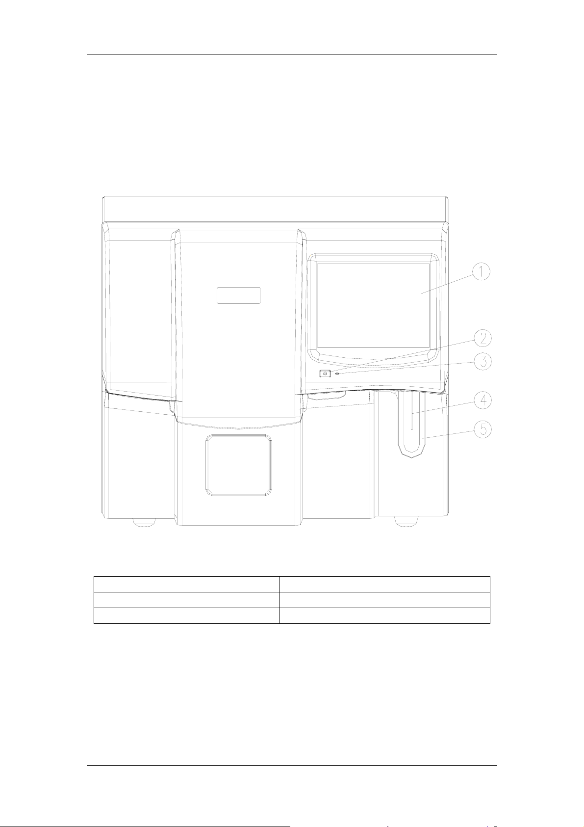
BC-5800 5-differential auto hematology analyzer consists of the main unit (analyzer),
pneumatic unit and accessories.
Figure 2-1 Front of the Analyzer
1----Touch screen 4----Sample probe
2----Power button 5----Aspirate key
3----Power indicator
2-4
System Structure
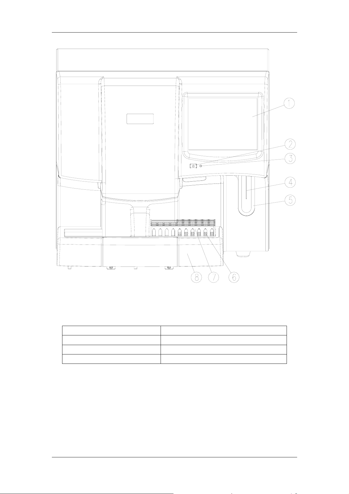
Figure 2-2 Front of the Analyzer (
1----Touch screen 5----Aspirate key
2----Power button 6----Sample tube
3----Power indicator 7----Tube rack
4----Sample probe 8----Autoloader
2-5
Autoloader Configured)
System Structure
1
2
21
20
19
18
17
16
15
14
10111213
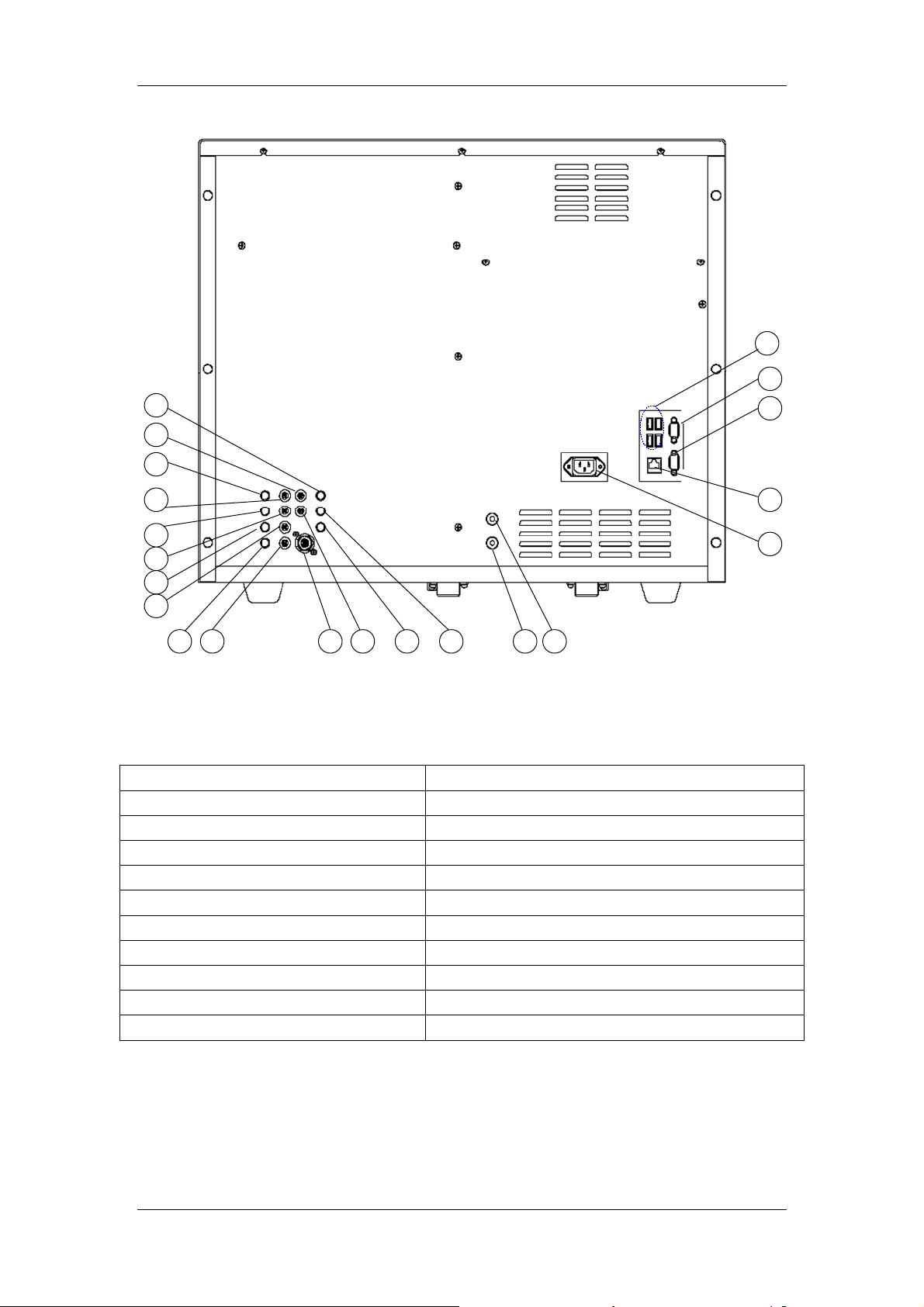
Figure 2-3 Back of the Analyzer
1----USB interface 12----M-58D diluent inlet
2----Reserved interface 13----M-58D diluent sensor BNC connector
3----Pneumatic unit control interface 14----M-58LBA lyse inlet
4----USB interface 15----M-58LBA lyse sensor BNC connector
5----Power input
6----Vacuum interface
7----Pressure interface
8----M-58 diluent sensor BNC connector
9----Waste sensor BNC connector 20----M-58LH lyse inlet
10----M-58 cleanser inlet 21----M-58LH lyse sensor BNC connector
11----Waste outlet
16----M-58LEO(Ⅱ) lyse inlet
17----M-58LEO(Ⅱ) lyse sensor BNC connector
18----M-58LEO(Ⅰ) lyse sensor BNC connector
19----M-58LEO(Ⅰ) lyse inlet
6789
3
4
5
2-6
System Structure
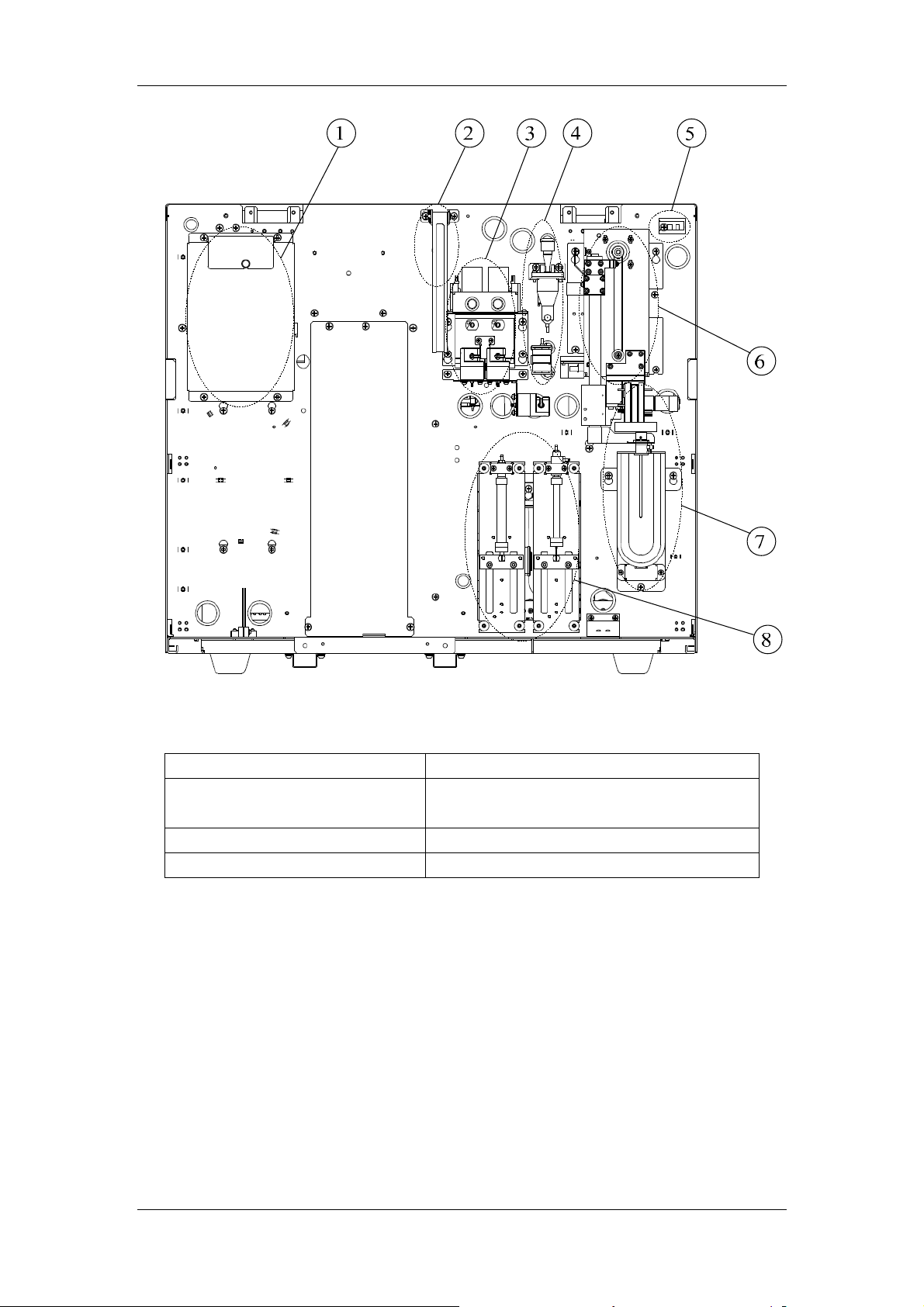
Figure 2-4 Front of the Analyzer (Front Cover Removed)
1----RBC & HGB bath unit 5----Cover photocoupler protecting unit
2----Cover support unit 6----Manual sampling and SRV(Sample
Rotator Valve) unit
3----WBC bath unit 7----START on/off unit
4----RBC premix bath unit 8----Syringes
2-7
System Structure
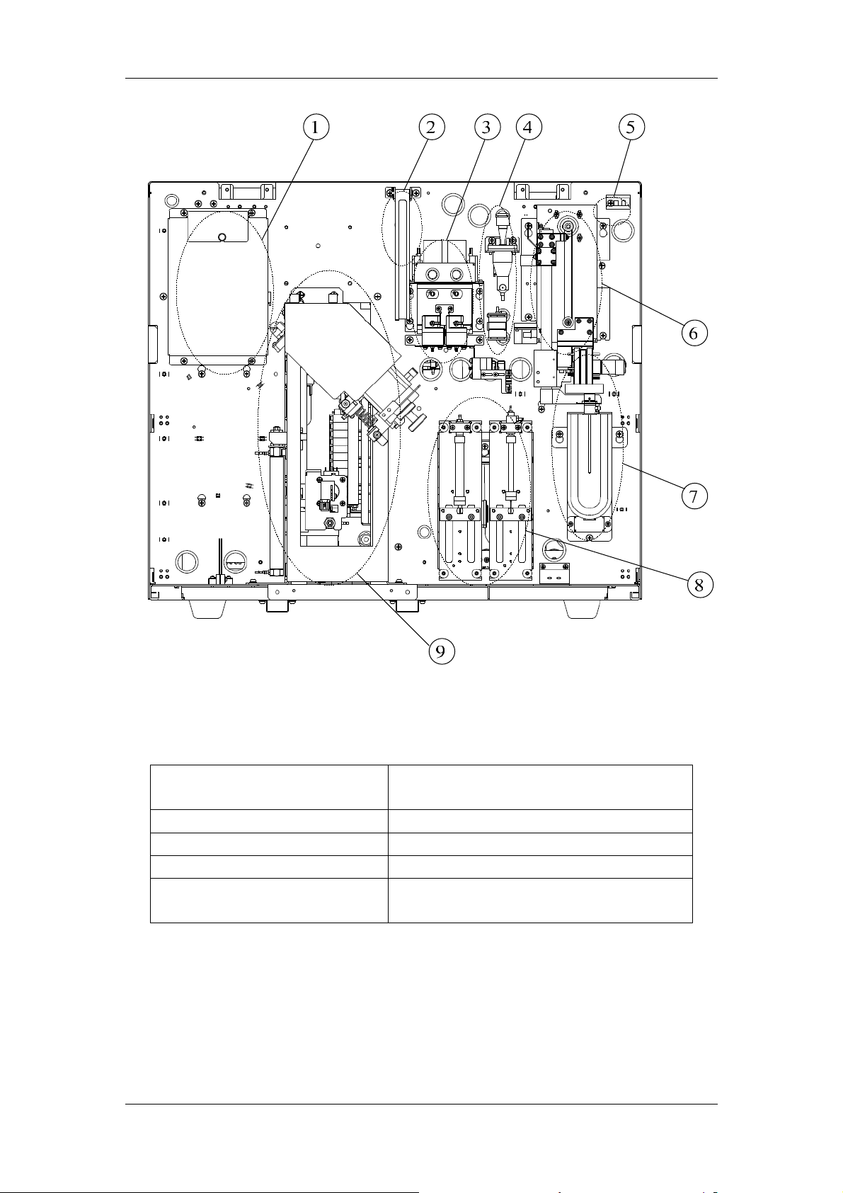
Figure 2-5 Front of the Analyzer (Front Cover Removed, Pierce & Mix Unit Configured)
1----RBC & HGB bath unit 6----Manual sampling and SRV(Sample
Rotator Valve) unit
2----Cover support unit 7----START on/off unit
3----WBC bath unit 8----Syringes
4----RBC premix bath unit 9----Pierce & mix unit
5----Cover photocoupler protecting
unit
2-8

System Structure
1
2
3
678
Figure 2-6 Inside Right of the Analyzer (Right Door Removed)
1----Optical system 5----Burkert valve unit
2----Valve & pump unit 6----Pinch valve unit
3----Cistern and waste chamber
unit
4----Waste five-way valve unit 8----Reagent preheating unit
7---- Waste chamber
4
5
2-9

System Structure
9 10 11 12
8
7
6
5
4
3
2
1
Figure 2-7 Inside Left of the Analyzer (Left Door Removed)
1----Power input 7----Pressure sensor board
2----Interface board 8----Fan
3----Filter 9----Hard disk unit
4----Air valve unit 10----Main board and signal board unit
5----Pressure regulator unit 11----PCB support bar unit
6----Power drive board unit 12----Volumetric unit
2-10
System Structure
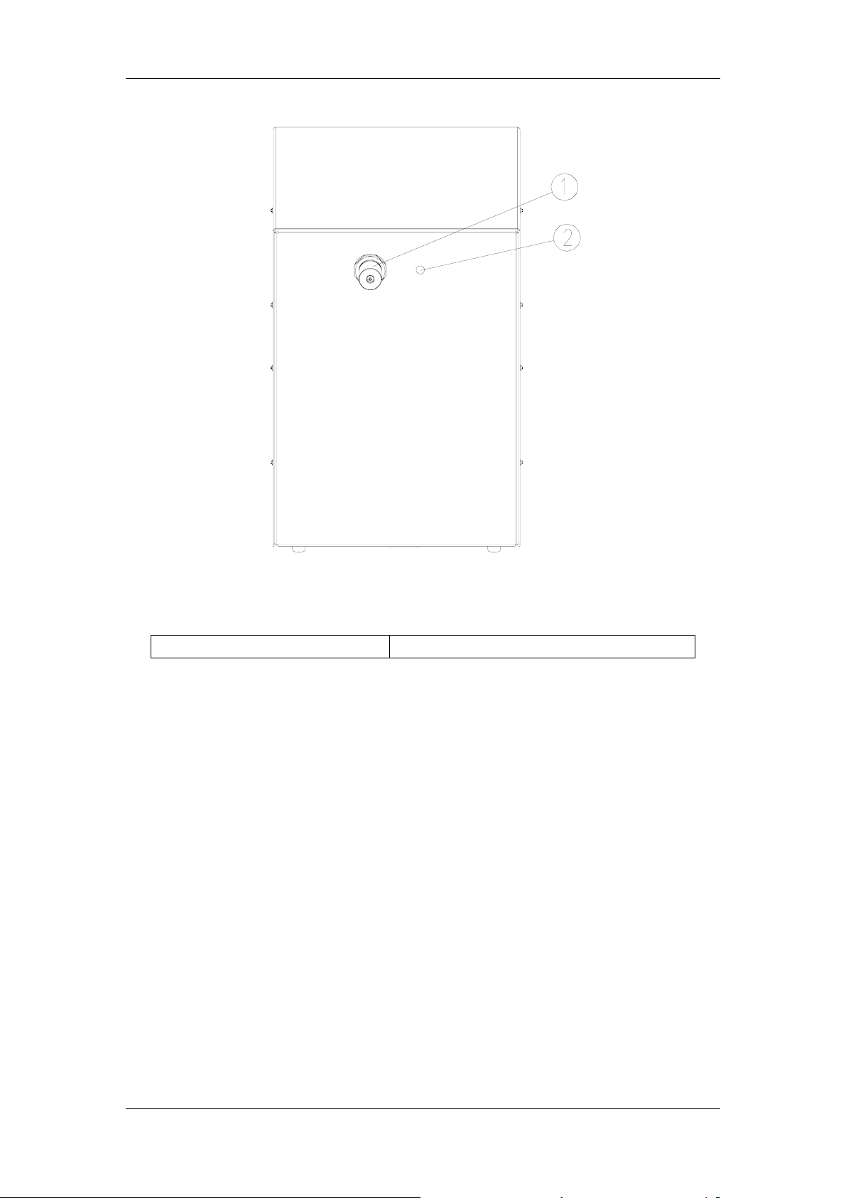
Figure 2-8 Front of Pneumatic Unit
1----Relief valve 2----Power indicator
2-11
System Structure
2.5 Software Structure
Software system can be divided into boot software, operation software and application
software. Boot software is autoloaded by hardware; its code runs in FLASH to configure
address space and to initialize system memory. Operation system completes the resource
initialization of CPU board, loading application software and transferring the CPU control
authority to application software. The code of application software runs in SDRAM, it obtains
the resource data needed from external hard disk to provide functions like counting,
parameter setting, quality control, device maintenance, data management, assistance, help,
etc. The application software sends control command to corresponding fluidic units at the
specified time according to the fluidic unit control sequence in basic sequence.
2.5.1 Menu Structure
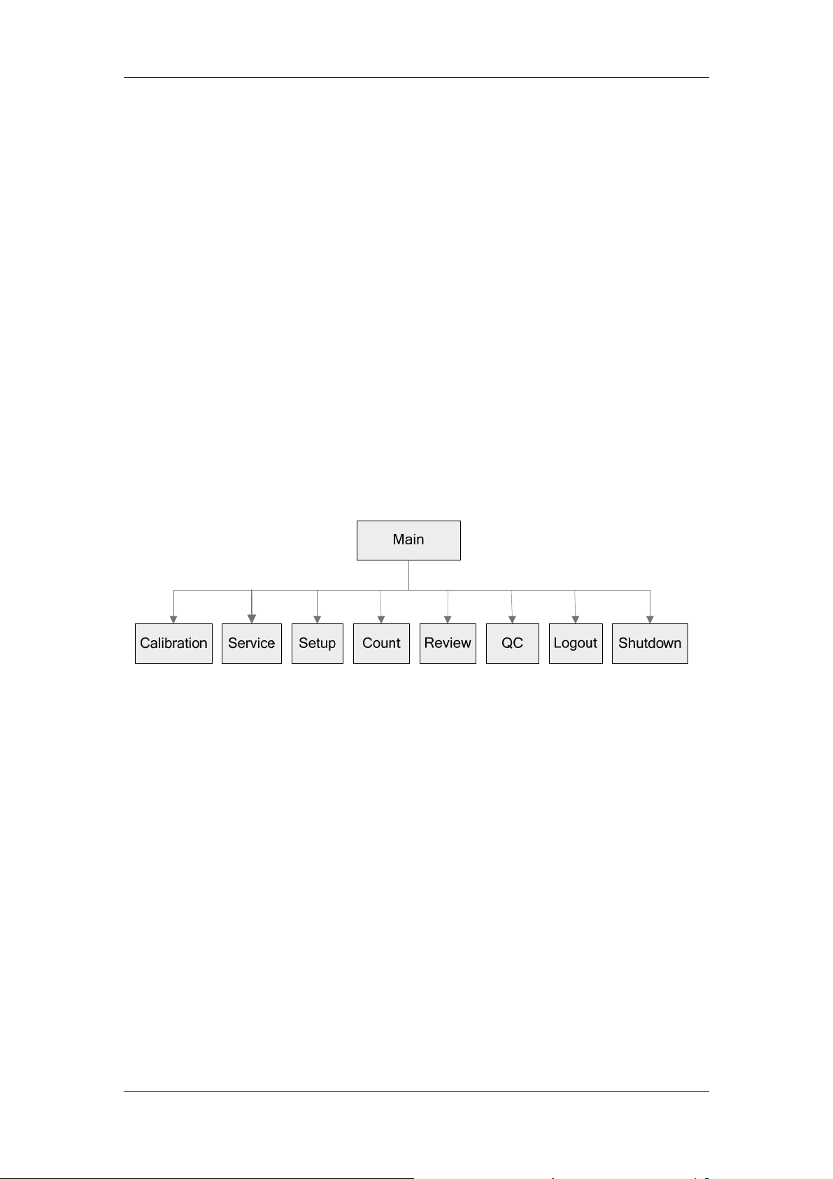
1. Main screen
There are 8 function icons in the main screen menu. Operators can click on the function
icons in the main screen to enter into corresponding screens to perform all functions of the
analyzer. See Figure 2-9 fo r the submenu structure of the main screen.
Figure 2-9 Menu Structure of the Main Screen
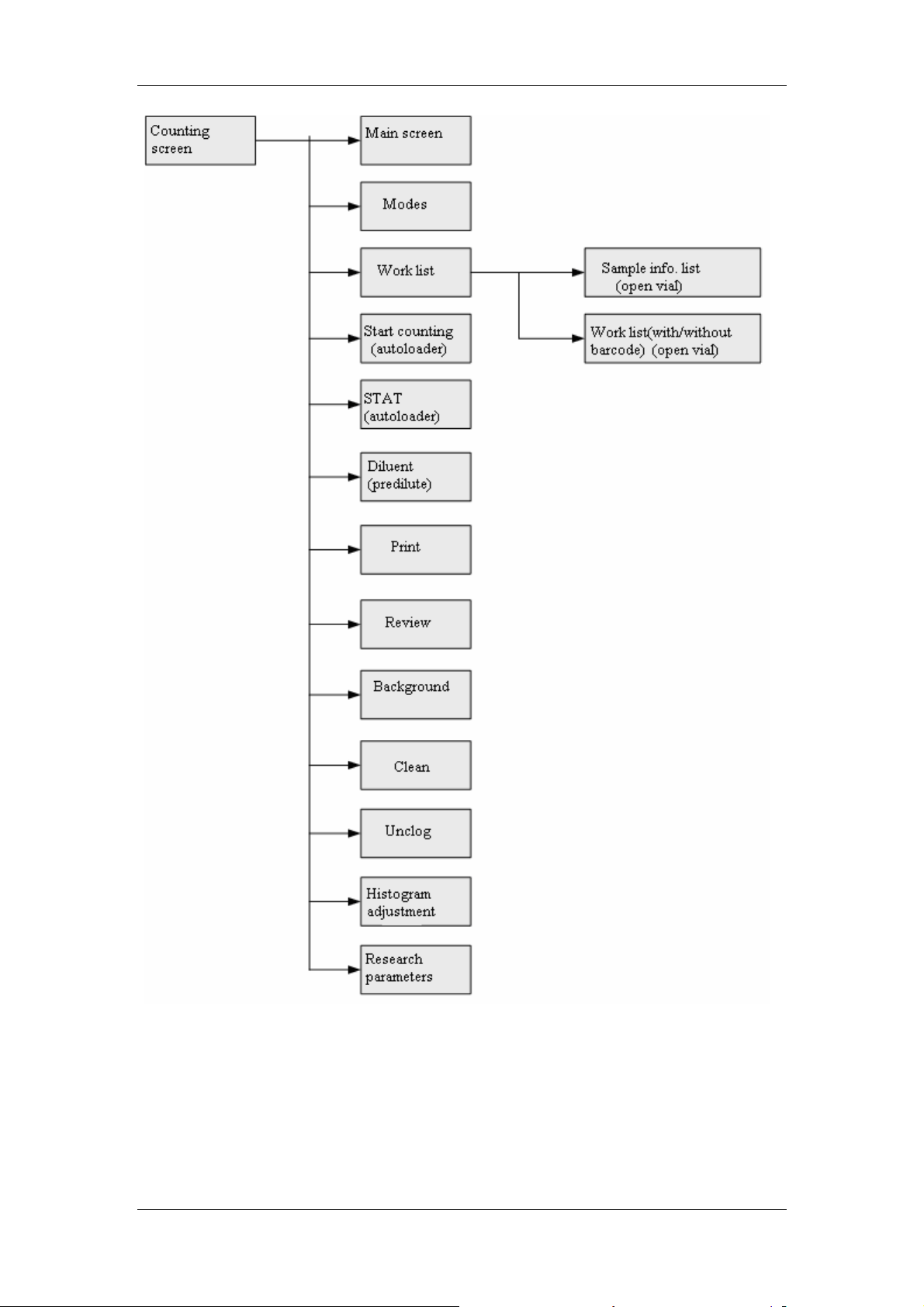
2. Counting screen
Counting screen comprises four parts: status region, measurement result and data region of
the current sample, data display region of the next sample and function button region.
Operators can click each function button in the counting screen to perform the functions of
the analyzer.
See Figure 2-10 for the menu structure of the counting screen:
2-12
System Structure
Figure 2-10 Menu Structure of the Counting Screen
3. Review screen
There are two modes of sample results review, table review mode and graph review mode.
When entering review screen from other screens, operators see the list review screen first.
See below for the menu structure of each screen:
Table review
2-13

System Structure
See Figure 2-11 for the menu structure of the table review menu:
Figure 2-11 Menu Structure of Table Review Mode
Graph review
See Figure 2-12 for the menu structure of the graph review mode:
2-14

System Structure
Figure 2-12 Menu Structure of Graph Review Mode
4. QC (Quality Control) screen
There are two QC programs: L-J QC and X-B QC. When switching to QC screen from other
screen, operators see L-J QC screen first.
L-J QC
See Figure 2-13 for the menu structure of L-J QC screen
2-15

System Structure
Figure 2-13 L-J QC Menu Structure
X-B QC
See Figure 2-14 for the menu structure of X-B QC screen
Figure 2-14 L-J QC Menu Structure
5. "Service" screen
"Service" screen includes "Maintenance", "Status", "Self-test", "Log", "Debug" and
"Initialization" screens. When switching to "Service" screen from other screens, operators
see the "Maintenance" screen first. See below for the menu structure of each screen:
2-16

System Structure
"Maintenance" screen
See Figure 2-15 for the menu structure of the "Maintenance" screen:
Figure 2-15 Menu Structure of the "Maintenance" Screen
"Status" screen
See Figure 2-16 for the menu structure of the "Status" screen:
2-17

System Structure
Service Main
Count
Maintain
Status
Self-test
Log
Init.
Debug
Figure 2-16 Menu Structure of the "Status" Screen
"Self-test" screen
See Figure 2-17 for the menu structure of the "Self-test" screen:
Version
Temp&Pres
Vol.&Cur.
Position
Func. Set
2-18

System Structure
Figure 2-17 Menu Structure of the "Self-test" Screen
"Log" screen
See Figure 2-18 for the menu structure of the "Log" screen:
2-19

System Structure
Figure 2-18 Menu Structure of the "Log" screen
"Debug" screen
See Figure 2-19 for the menu structure of the "Debug" screen:
2-20

System Structure
Figure 2-19 Menu Structure of the "Debug" Screen
"Initialization" screen
See Figure 2-20 for the menu structure of the "Initialization" screen:
2-21

System Structure
Service Main
Count
Maintain
Status
Self-test
Log
Init.
Debug
Set init.
Runs init.
Figure 2-20 Menu Structure of the "Initialization" Screen
7. "Setup" screen
"Setup" screen includes "User", "Setting" and "Advance" screens. When switching to
"Setup" screen from other screen, operators see "Setting" screen first. See below for the
menu structure of each function screen:
Setting
See Figure 2-21 for the menu structure of the "Setting" screen:
2-22

System Structure
Figure 2-21 Menu Structure of "Setting" Screen
2-23
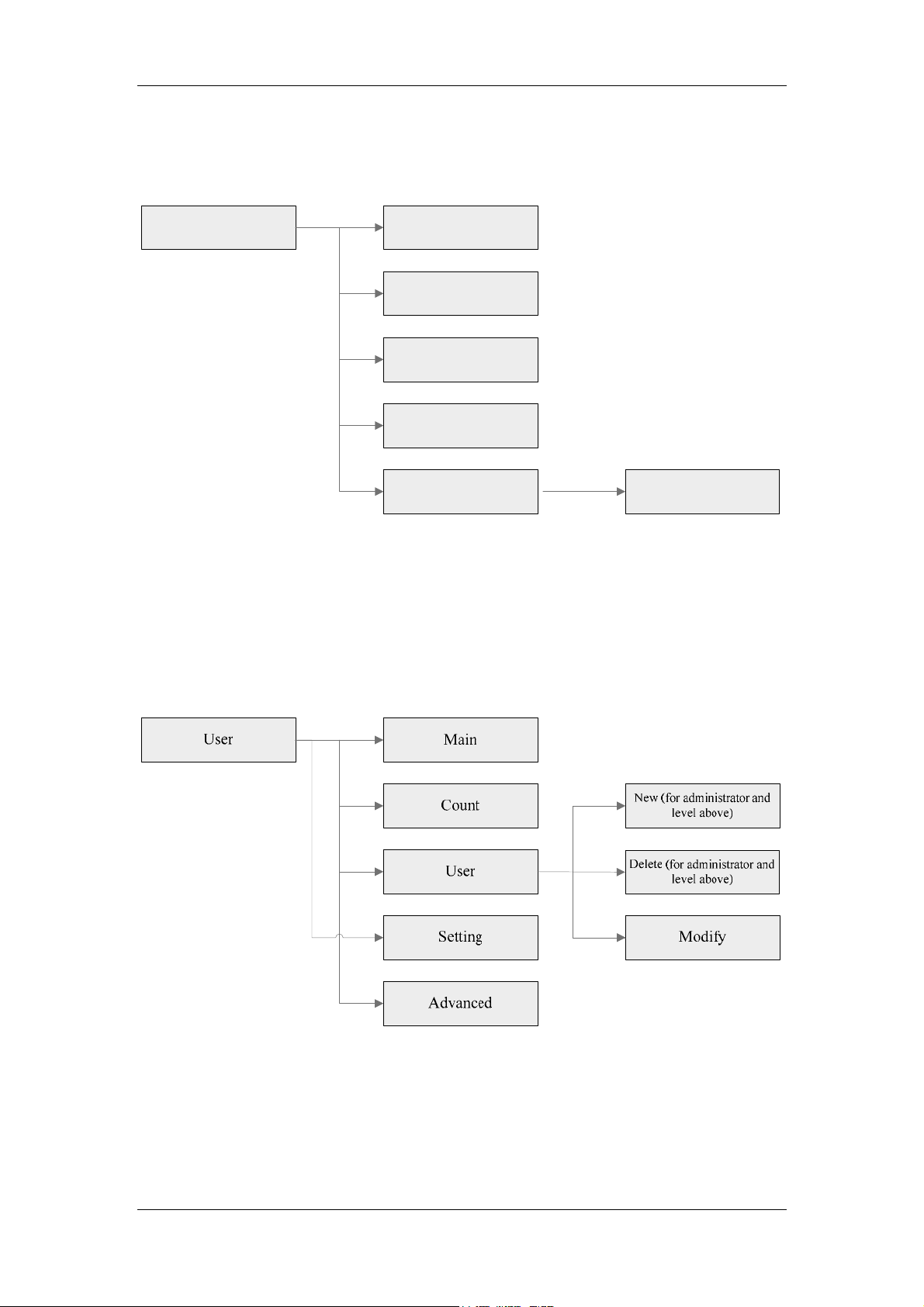
Advanced
System Structure
See Figure 2-22 for the menu structure of the "Advanced" screen:
Advanced Main
Count
User
Setting
Advanced
Figure 2-22 Menu Structure of "Advanced" Screen
Service
User Management
See Figure 2-23 for the menu structure of the "User" screen:
Figure 2-23 Menu Structure of the "User" Screen
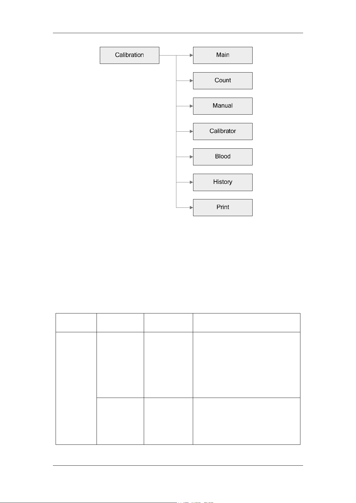
8. Calibration screen
2-24
System Structure
Figure 2-24 Menu Structure of the "Calibration" screen
2.5.2 Password
There are three levels of password: common user level, user administrator level and service
engineer level. The authorities of user administrator level cover all those of the common user
level, and the authorities of the service engineer level cover all those of the user administrator
level. See Table 2-1 for the permitted functions under each level of password.
Table 2-1 Function Comparison Table of All Levels of Password
Password
level
Common
user
Module Screen Permitted Functions
Counting Counting Switching count mode, editing data of
the next sample, implementing count,
adding diluent, printing results of the
current sample, implementing
background count, unclogging,
cleaning, auto-sampling, STAT and
reviewing research parameters.
Review Table review Browsing sample records, editing
sample information (sample ID cannot
be altered), CV, and trend, selecting,
searching for and printing sample
data, switching
2-25

User
administrator
System Structure
Graph review Editing sample information, printing
sample data and research parameters
LJ QC setup, LJ QC count, LJ QC
LJ QC
graph and LJ QC table
XB QC setup and control, XB QC
QC
Calibration
Setup
XB QC
Manual
calibration
graph, XB QC table
Manual calibration result browsing
and printing
User User management(altering username,
password and operator's information)
Setting Setting date and time, assistance
settings and reagent expiration date.
Service
Self-test Mechanical self-test, valve self-test,
circuit self-test
Log
Includes "All", "Parameter Setup"
and "Others". Error information and
run sequence records cannot be
viewed in "All"
Status Version, temperature and pressure,
voltage and current, position and
photocoupler, and configuration
Maintenance Replacing/priming, cleaning,
maintaining, overall maintenance
Counting Counting Adjust histogram
Review
Table review 1 Delete sample data (set the deleting
authority for administrator in "Setup"
screen)
2 Modify sample ID
3 Check sample data
Graph review 1 Adjust histogram
2 Modify sample ID
3 Check sample data
Calibration
Manual
calibration
Modify open vial-whole blood, open
vial-predilute calibration parameters
and print
Calibrator Calibration under open vial-whole
blood and open vial-predilute mode
Fresh blood Calibration for fresh blood under open
vial-whole blood and open
vial-predilute mode
Calibration
history
Browsing and printing calibration
history
2-26

System Structure
Service
engineer
Setup
User 1 Add users
2 Delete users
3 Modify user information
Setting Print device parameters,
communication parameters, counting
report printing setup, autoloader stop
condition, gain setup (HGB setting),
reference range (general, man,
woman, child, neonate, user-defined),
counting parameter units, RBC count
time, department and sender ID
setup, tube barcode setup (autoloader
configured)
Service
Initialization Can initialize parameter units and
reference range, and print device
information
Self-test Can perform touch screen calibration
Log
Display "All", "Parameter Setup",
"Others" and "Error Information".
Run sequence records and log of
operations of service engineer level
cannot be viewed in "All".
Counting Counting
Review
Table review 1 Export data to USB (sample data
export, scattergram export)
2 View and print repeatability and
trend graph
3 Delete sample data
Graph review Display and print special information
of samples
Calibration
Modify calibration parameter under
open vial-whole blood and open
vial-predilute mode; modify the related
parameters under autoloader-whole
Manual
calibration
blood or closed tube-whole blood
mode
Modify calibration parameter under
open vial-whole blood and open
vial-predilute mode; modify the related
parameters under autoloader-whole
blood or closed tube-whole blood
Calibrator
mode
2-27
System Structure
Setup
Service
Advanced
setting\service
engineer
1 set auto-entry Flash mode
2 Languages
3 Device serial numbers
4 Volume setup for RBC volumetric
tube
5 Sample record deletion authority
setup
6、print bind reference range and its
flags
Gain Set the current value of all gains
Log
1 Display log type: "All", "Parameter
Setup", "Others", "Error
Information" and "Run Sequence".
All records can be viewed
2 Can export log with USB
Status 1 View version information of CD and
algorithm in version screen
2 View Temp. PID
(Kp,Ti,Td,T(S),SP(℃)) in temperature
& pressure screen
Self-test Temperature and pressure calibration
can be done in self-test screen
Initialization View runs initialization
Debug 1 Importing data with USB
2 Wipe block debug
3 Mix unit debug.
Maintenance Software upgrade (USB upgrade)
2-28

3 Fluidic System
3.1 Introduction of Fluidic Parts
3.1.1 Needles
Sample probe: connects to SRV (Sample Rotary Valve) for sample aspiration under
open vial mode.
Piercing needle: connects to piercing mechanism for sample aspiration under
autoloader mode.
Sample flow probe: connects to flow cell for the formation of sample flow in WBC
detection unit.
3.1.2 Probe Wipe
Probe wipe for sample probe: locates below SRV, its function is to wash the interior
and exterior of the sample probe.
Probe wipe for piercing needle: locates in piercing mechanism, its function is to
wash the interior and exterior of the piercing needle.
3.1.3 Pumps
Metering pump: metering part, aspirates fluid by negative pressure, and then
switches to negative pressure to drain fluid, providing reagent of a predetermined
amount for sample analysis. For specific models and function, please refer to
Appendix D3.
Syringes: aspirates and dispenses sample and reagent quantitatively. 1
2.5ml-syringe and 1 100ul-syringe. The first one is mainly used to aspirate sample
and diluent for cleaning open vial and piercing probe wipe; the latter one is mainly
used to push sample flow.
3.1.4 Valves
Fluidic valve: controls fluid or air flow direction.
Pinch valve: starts/stops the fluid flow. For the quantity and function, please refer to
Appendix D4.
3-1

Fluidic System
Check valve: controls the unidirectional flow of fluid or air. For the quantity and
function, please refer to Appendix D5. See Figure 3-1 for the direction of check
valve.
Figure 3-1 Check Valve
SRV: metering part, provides a pre-determined amount of sample for analysis. See
Figure 3-2 - Figure 3-4.
3-2

Figure 3-2 Open vial feeding position SRV fluidic status
3-3

Fluidic System
Figure 3-3 Autoloading position SRV fluidic status
3-4

Fluidic System
0
2
Figure 3-4 SRV tube interfaces
Serial
Hole position
No.
1. HGB6ul (open vial) 13.
2. RBC6ul (open vial) 14.
3. 15.
DIFF20ul (open vial)
4.
5. 17.
BASO 20ul (open vial)
6.
7. HGB6ul (autoloading) 19.
8. RBC6ul (autoloading) 20.
9. 21. Open vial positioning hole
DIFF20ul (autoloading)
1
11 23. Peripheral cleaning channel
BASO 20ul (autoloading)
1
Serial
number
RBC sample (first dilution) 62.5ul
16.
18.
22. Piercing positioning hole
24. /
RBC sample (first dilution) 62.5ul
Hole position
(open vial)
(autoloading)
3.1.5 Cisterns and Waste Cisterns
DIL cistern: diluent cistern, for sample diluting and cleaning.
FCM cistern: sheath fluid (diluent) cistern, for WBC detection and cleaning.
Cleanser cistern: cleanser cistern, for cleanser maintenance.
WC1 waste cistern: waste cistern, gathering waste of WC2, WC3 and other
channels.
WC2 waste cistern: waste cistern, gathering waste of WBC unit.
WC3 waste cistern: waste cistern, providing stable negative pressure during RBC
counting and gathering waste of RBC unit.
3-5

Fluidic System
3.1.6 Baths
WBC bath: includes DIFF bath and BASO bath; DIFF bath is for the reaction of WBC
4-differential sample,
BASO bath is for the reaction of sample testing basophils.
Flow cell: it is the part facilitating WBC testing; sheath fluid forms here.
RBC premix bath: RBC channel, it is for the first dilution of sample in RBC channel.
RBC bath: RBC/PLT detection unit where the test on RBC/PLT completes.
HGB bath: HGB detection unit where the HGB test completes.
Volume tube: controls the volume of RBC/PLT testing sample.
3-6

Fluidic System
3.2 Introduction of Pneumatic Parts
3.2.1 Pneumatic System
Pneumatic system provides pressure to support the normal operation of the analyzer.
Pneumatic unit provides pressure and vacuum to the analyzer at the same time; the pressure
is regulated to 0.25MPa within the pneumatic unit and then starts output. After the analyzer
receives the pressure and vacuum from the pneumatic unit, a drying filter filtrates and dries the
pressure, and then regulates it to 0.07MPa and 0.16MPa; the vacuum is also regulated to
–0.04MPa.
See the following Figure 3-5 for the pneumatic system.
Figure 3-5 Pneumatic system
3.2.2 The Functions of Air Pressure
See the following Table 3-1 for the functions of air pressure.
Table 3-1 Illustration on using pressure
Type Name Function
Pressure
0.25MPa Driving cylinder and pinch valve.
0.16MPa Forming sheath fluid.
0.07MPa Draining waste;
3-7

Fluidic System
Draining reagent for metering pump, DIL cistern and cleanser
cistern.
Vacuum
-0.085MPa
-0.04MPa
Aspirating reagent for metering pumps and cisterns.
WC1 cistern aspirates waste.
3.2.3 Valves
Air valve: controls the directional flow of air.
Pressure regulator: regulates pressure coming out directly from the pneumatic unit to
meet requirement on all kinds of pressure.
3.2.4 Filters
Pressure filter: filtrates and dries the air with pressure coming directly out from the
pneumatic unit.
Small filter: connects to FCM cistern, filters small impurities in diluent coming out
from FCM cistern.
Figure 3-6 Small filter
3-8

Fluidic System
3.3 Fluidic System
3.3.1 Reagent Volume Required
Sample analysis for a single sample each time
The analysis modes include open vial whole blood, autoloading whole blood and
predilute mode, each mode is divided into CBC+5DIFF and CBC, so there are
altogether 6 modes.
CBC+5DIFF mode
Reagents Name
M-58 diluent M-58D diluent 58mL 60ml 58ml
M-58LEO(I) lyse 1.56mL 1.56mL 1.56mL
M-58 lyse
M-580LEO(II) lyse 0.32mL 0.32mL 0.32mL
M-58LBA lyse 1.56mL 1.56mL 1.56mL
M-58LH lyse 1.0mL 1.0mL 1.0mL
Open vial
whole blood
Autoloading
whole
blood
CBC mode
Reagents Name
M-58 diluent M-58D diluent 48mL 50ml 48mL
M-58LEO(I) lyse - - -
M-58 lyse
M-58LEO(II) lyse - - -
M-58LBA lyse 1.56mL 1.56mL 1.56mL
M-58LH lyse 1.0mL 1.0mL 1.0mL
Open vial
whole blood
Autoloading
whole
blood
Predilute
Predilute
Normal startup function
Reagent volume required:
Reagents Name
M-58 diluent M-58D diluent 216ml
M-58 lyse
Cleanser for
hospital use
Reagent volume required
when starting up normally
M-58LEO(I) lyse 5.2ml
M-58LEO(II) lyse 1.28ml
M-58LBA lyse 5.2ml
M-58LH lyse 4.0ml
M-58 cleanser
3-9
-

Fluidic System
Startup after emptying(prepare to ship)
Reagent volume required
Reagents Name
M-58 diluent M-58D diluent 674ml
M-58LEO(I) lyse 13.52ml
M-58LEO(II) lyse 8.96ml
M-58 lyse
M-58LBA lyse 15.6ml
M-58LH lyse 9ml
Cleanser for
hospital use
M-58 cleanser 142ml
Reagent volume
Notes
required when starting
up after
emptying(prepare to
ship)
Volume consumed is
414ml, 260ml reagent
is stored in tubing and
cisterns
Volume consumed is
8.22ml, 5.3ml reagent
is stored in tubes
Volume consumed is
5.58ml, 3.38ml
reagent is stored in
tubes
Volume consumed is
12.3ml, 3.3ml reagent
is stored in tubes
Volume consumed is
5.8ml, 3.2ml reagent
is stored in tubes
Volume consumed is
25ml, 117ml reagent is
stored in tubes and
cisterns
Shutdown function
Reagent volume required:
Reagents Name
M-58 diluent M-58D diluent 11ml
M-58 lyse
Cleanser for
hospital use
M-58LEO(I) lyse -
M-58LEO(II) lyse -
M-58LBA lyse -
M-58LH lyse -
M-58 cleanser
3-10
Reagent volume
required when shutting
down normally
49ml

Fluidic System
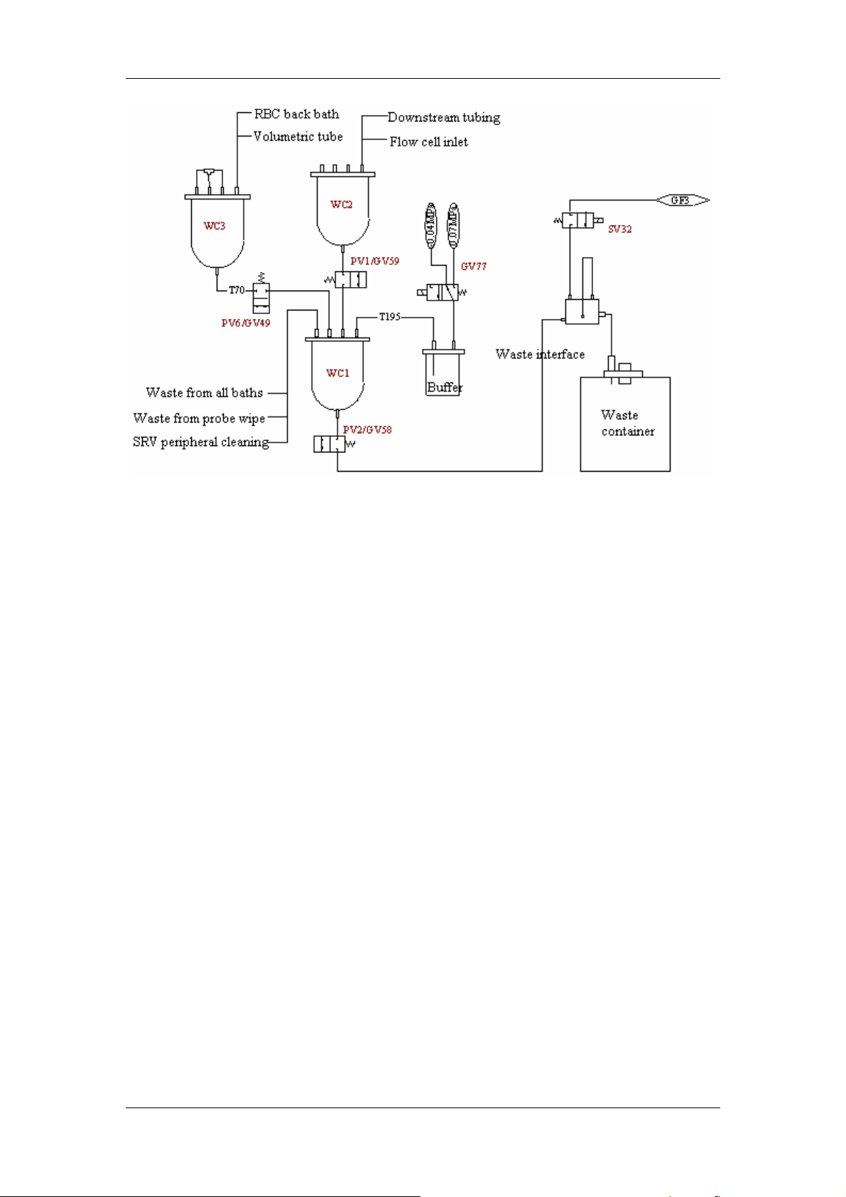
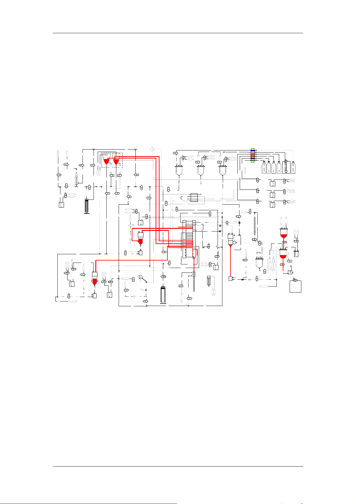
3.3.2 Fluidic System Drawing
Figure 3-7 Fluidic system
3.3.3 WBC Channel
BASO Channel
Reagents used:
LBA lyse: lyses RBC, PLT and turns WBC (excluding basophils) into naked nucleus cells;
Diluent: cleaning, and providing sheath fluid
Detection principle: flow cytometry and semi-conductive laser scatter technology
Detection parameters: WBC, BASO# and BASO%
Diagram information: WBC scattergram
Dilution ratio: 1:52
Metering volume: 50.9µl
Function description: the sample is diluted in the bath to the ratio of 1:52, and then
the dilution moves to the flow cell. Meanwhile sheath fluid is started and stabilized.
After that, the dilution moves to the measuring segment of the flow cell. Sample
syringe pushes the dilution, which is surrounded by the sheath fluid, through the flow
cell for optical measurement at a stable speed within certain amount of time. Then
clean the measurement tube to restore its original status.
3-11

Fluidic System
DIFF Channel
Reagents used:
LEO(I) and LEO(II): lyses RBC and performs dissimilation treatment to various types of WBC;
Diluent: cleaning, and providing sheath fluid
Detection principle: flow cytometry and semi-conductive laser scatter technology
Detection parameters: MONO#, MONO%, LYMPH#, LYMPH %, NEUT#, NEUT%,
EOS# and EOS%
Diagram information: DIFF scattergram
Dilution ratio: 1:68
Metering volume: 61.7µl
Function description: the sample is diluted in the bath to the ratio of 1:68, and then
the dilution moves to the flow cell. Meanwhile sheath fluid is started and stabilized.
After that, the dilution moves to the measuring segment of the flow cell. Sample
syringe drives the dilution, which is surrounded by the sheath fluid, through the flow
cell for optical measurement at a stable speed within certain amount of time. Then
clean the measurement tube to restore its original status.
Fluidic Disposition of WBC Channel
Aspirating and metering sample and reagent: aspirate sample into SRV with whole
blood aspirating syringe, and then DP1 aspirates the pre-determined amount of
reagent and dispense the reagent into DIFF bath. DP2 and DP3 both aspirate certain
amount of reagent and then dispense the DIFF and BASO samples into DIFF and
BASO baths.
Mix: mix the sample with reagent by jet flow produced when dispensing the sample
and by using the mixing bar in DIFF and BASO bath.
Clean: clean the bath with fluid in DIL cistern through energizing fluidic valve SV17
and pinch valve PV11 and PV12.
Waste drainage: drain the waste with WC1 vacuum by energizing SV30 and SV31.
3.3.4 RBC/PLT Channel
RBC/PLT Channel
Reagents used:
Diluent: diluting and cleaning, providing conductive environment and isovolumetric treatment
to cells
Detection principle: aperture impedance method
3-12

Fluidic System
Detection parameters: RBC and PLT
Diagram information: RBC histogram and PLT histogram
Dilution ratio: 1:18000
Metering volume: 300µl
The function of RBC channel is to count RBC and PLT in blood sample, the method adopted is
impedance method. During the detection, blood sample needs to be diluted to the ratio of
1:18000, which is hard to achieve with a single dilution, so the second dilution needs to be
conducted. First dilute the sample to the ratio of 1:433 and dispense it in to the premix bath;
and then aspirate the 1:433 sample back into the SRV and redilute it to the ratio of 1:41.6,
finally dispense it into RBC bath to form the 1:18000 sample.
RBC/PLT Channel Disposition
Aspirating and metering of sample and reagent: First dispense the sample that is
measured by SRV through 2.6ml metering pump DP8 and SV22 into RBC premix
bath, aspirate the sample that is diluted for the fist time with 1ml metering pump, and
then dispense the diluted sample into RBC counting bath through metering pump
DP8, SV22 and SV05.
Mix: bubble mix and jet flow mix;
Clean: add diluent into the RBC counting bath through DP8, SV22 and SV05 to clean
the bath; add diluent in to the premix bath through DP6 and SV23 to clean the bath;
Waste draining: RBC premix bath drains waste by WC1 vacuum and SV29; RBC
counting bath drains waste by WC1 vacuum and SV36;
3.3.5 HGB Channel
HGB Channel
Reagents used:
Diluent: to dilute and clean
HGB lyse: to lyse RBC and mix with HGB
Detection principle: colorimetric method
Detection parameter: HGB
Dilution ratio: 1:500
The detection principle of HGB channel is colorimetric method, HGB concentration is
obtained by comparing the intensity of light passing through the sample with blank
reference reading.
HGB Channel Disposition
Aspirating and metering sample and reagent: dispense the sample in SRV into HGB
3-13
Fluidic System
bath through DP7 and SV19, meanwhile dispense certain amount of lyse into the
bath through DP5 and SV28;
Mix: bubble mix and jet flow mix;
Clean: dispense diluent into the HGB bath through DP7 and SV19 to clean the bath;
Waste draining: drains waste by WC1 vacuum and SV35;
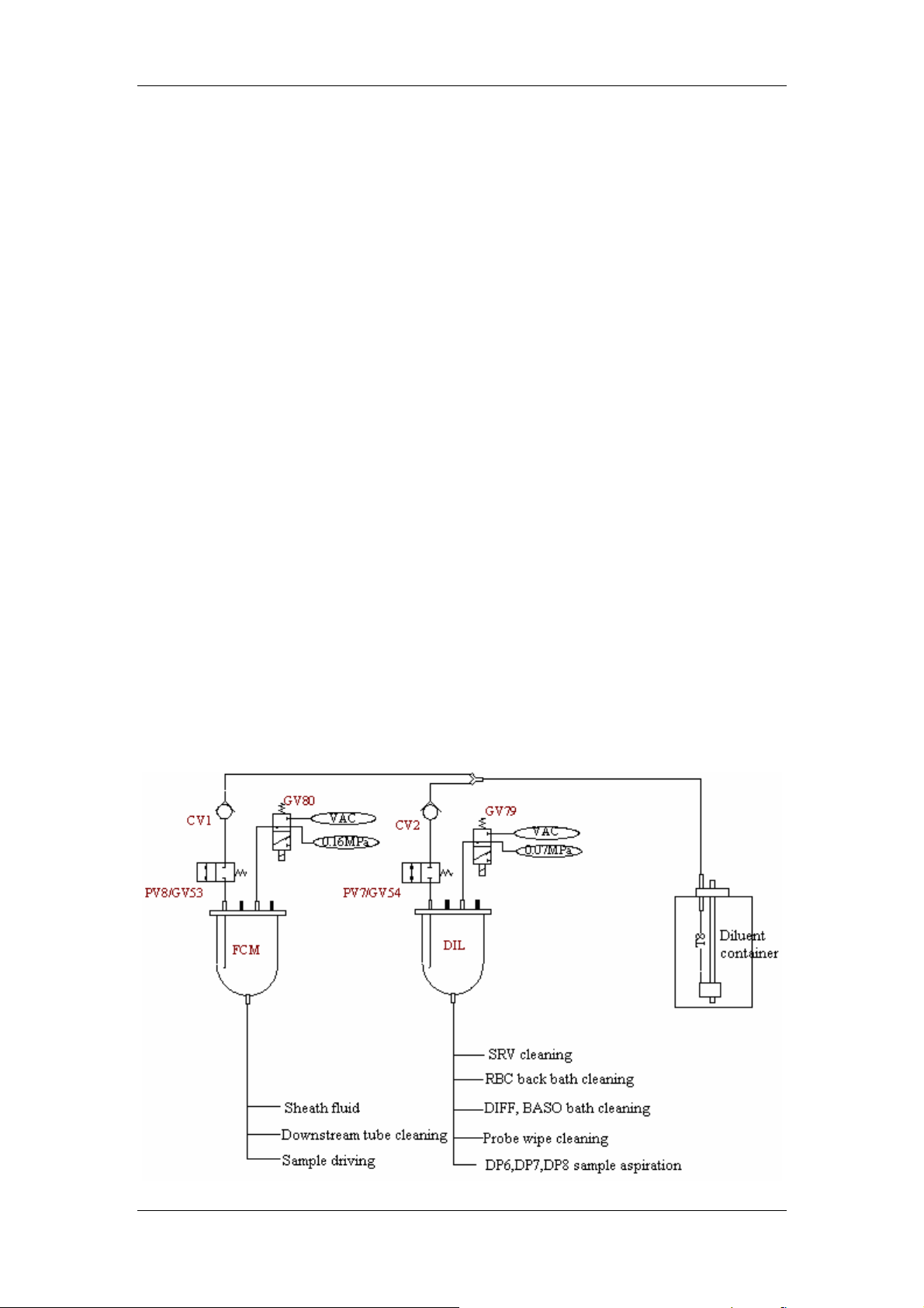
3.3.6 Fluid Feeding and Draining Channel
Fluid feeding and draining channel includes DIL cistern, FCM cistern, waste cistern WC1, WC2
and WC3. See Figure 3-8 for the fluidic system connection. DIl and FCM cistern units both
have a three-way valve and a pneumatic pinch valve apart from the cistern. The three-way air
valve switches pressure for the cistern. Under pressure (DIL cistern: 0.07Mpa, FCM cistern
0.16Mpa), the cistern feeds fluid to the fluidic system and provides pressure as a driving force;
under vacuum, the three-way air valve helps to energize the pinch valve, the cistern is then
filled with fluid (from the diluent container). WC2 is an open container with air pressure; its
outlet is connected to WC1 through pneumatic pinch valve PV1. Energize PV1, waste in WC2
flows to WC1. WC3 is a closed container; its outlet is connected to WC1 through pneumatic
pinch valve PV6. Energize PV6, waste in WC3 flows to WC1, meanwhile WC3 stores vacuum
for RBC counting, and RBC bath and volumetric tube cleaning.WC1 also has a three-way air
valve and a pneumatic pinch valve. The energizing/de-energizing of the air valve switches the
pressure of WC1 between pressure (0.07Mpa) and vacuum (
can gather waste in all channels; under pressure, it helps to energize PV2 to drain waste into
waste container. The inlet of waste pump is connected to the waste draining outlets of all
channels; its outlet is connected to waste container.
The corresponding channels of each cistern, waste cistern and waste pump are marked in
Figure 3-8.
–0.04Mpa). Under vacuum, WC1
3-14
Fluidic System
Figure 3-8 The fluidic connection chart of cistern and waste channels
3.3.7 Sampling and Blood Dispensing Channel
Sampling and blood dispensing modules include: SRV and its controlling cylinder, peripheral
cleaning channel, probe wipe and whole blood aspirating syringe. The function of blood
dispensing and sampling channel is to aspirate certain amount of sample into SRV, complete
sample metering through the rotation of SRV, and then dispense certain amount of sample into
corresponding baths by metering pumps. The function of peripheral cleaning channel is to
clean the sample that is spilled out when SRV is rotating and avoid sample from leakage.
Probe wipe cleans the interior and exterior of sample probe.
3.3.8 Shutdown Cleanser Cleaning Disposition
Cleanser cleaning drive: the cleaning drive is the pressure of 0.07MPa in the
cleanser cistern and whole blood aspirating syringe, each is for a different cleaning
area. 0.07MPa pressure cleans all baths and flow cell; the syringe cleans SRV and
sample probe;
Cleanser cleaning procedure: energize fluid valve SV13 and the cleanser control
valves of all baths, dispense certain amount of cleanser into the baths by pressure to
clean them.
3-15
Fluidic System
3.4 Basic Cycle Design Description
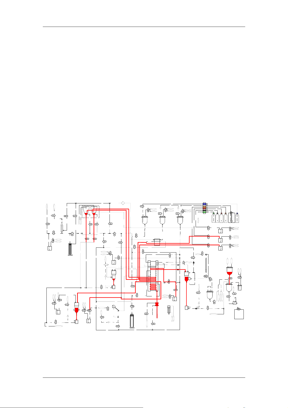
3.4.1 Open Vial Whole Blood Measurement Cycle
0-11s, see the red lines in Figure 3-9
SRV is at the working position, that is SRV bar stays at the upper position.
During 0-3.6s, aspirate the sample to SRV from manual sample flow probe through
whole blood syringe SV09 and SV10;
Start probe wipe to clean the exterior of the open vial sample probe;
Empty RBC premix bath, RBC bath, HGB bath, DIFF and BASO bath;
Add 2ml diluent to HGB bath through DP7 and SV19, wait for 3.5s until the dilution
becomes stable, measure background voltage and then empty HGB bath;
Dispense diluent into RBC bath through DP8, SV22 and SV5 to clean the bath and
then empty it;
Dispense LEO I lyse and LBA lyse into DIFF bath and BASO bath respectively to
clean the baths, then empty them;
Empty waste cistern.
J27-T351-J104
2
2
C
W
T185
SV8
T184
T182
C2
T183
DP4
1.5mL
C24
T214 T212
C25
T186
T43
C12
T47
J25-T42-J26
T128
LF1
T38-J105
5
9
J
1
SV1
3
T
6
2
1
9
P
P
J
-
6
5
1
1
2
2
T
T
2
2
J
C11
3
5
T154
T155
1
T
1
2
J
SV11
SV12
GV76
SV23
T78
DP6
1mL
T80
预混池
隔离室
T141
穿
刺
9
P
6
2
1
T
2
7
J
T127
T123
SV20
T122
C34
C13
T158
6
5
1
T
1
6
1
T
C15
7
5
1
T
4
6
1
T
C16
5
6
J81-T95
1
T
C17
6
6
1
T
4
SV16
7
J
7
6
1
T
3
T148-P4-P3
7
J
C35
T144
C19
T136
T143
针
SV9
T142
J71-T125
C33
T124
C32
GV78
SV15
4
1
VAC
T
0.07MPa
C36
5
1
T
PV8/GV53
M-50
T160
C14
SV13
J23-T159-J24
SV18
T162
SV10
C18
E
G
L
N
I
m
R
5
.
Y
2
S
_
P
T121
T39-J30
J75-T145-J76
T40-J34-T35
T77
PV4/GV56
C39
SV14
T79-J80
J79-T137
J31-T41
J33-T33
J32-T41
G2
G1
K
D2
D1
F2
F1
B1
A2
7
4
1
T
8
7
J
C66
T100
液
废
4
V
P
12
8
T73-J57
L M
H
分血阀
J77-T146
T99
C42
J69-T98-J70
SV21
7
9
T
C43
预加热池组
1
2
C
T44
W
T181
SV6
J1-T180-J2
T179
流动室
SV7
J3-T178-J4
VAC
0.07 MPa
GV75
H
a
L
P
M
7
SV28
VAC
0
.
0
GV70
J91-T140-J92
DP5
1mL
SV35
T213
WC1-废液
T45
SV3
SV2
C1
J7-T49-J8
J11-T48-J12
C3
T175
J5-T177-J6
C4
PV10/GV52
J9-T176-J10
E
G
L
N
I
µ
0
R
0
Y
1
S
_
S
T204
J93-T139-P5-J94
0.07MPa
HGB池
0
1
GV65
2
T
C27
T209
T205-J88-T206-J87-T207
CV6
J89-T208-J90
T211
C26
隔离室
1
0
2
2
0
T
2
T
板
板
前
前
C6C5C7
J13-T174-J14
T200
T203
0.07MPa
GV73
BASO
C22C23
J86-T138-P6
VAC
DIFF
3
7
1
T
2
7
1
T
9
4
1
T
T135
3
3
1
T
C29
C8
J19-T151-J20
T150
C9
VAC
0.07MPa
GV66
C20
CV5
SV29
T119
P
V
废
5
-
液
0.07MPa
GV68
T130
T129
C30 C31
T152
C10
SV17
0
.
0
7
M
P
a
7
1
1
T
T116
T112-J83-T113-J82-T114
J84-T115-J85
T118
C21
封闭进样拭子
PV5/GV55
CV4
T131
T46
T218
0
7
1
T
9
6
1
T
PV11/GV51PV12/GV50
8
7
9
9
1
1
T
T
J17-T168-J18J15-T171-J16
SV31
SV30
T199
T120
C28
T132
SV19
T134
DP7
2mL
T13
C45
T19
T20
GV80
CV1
T22
FCM
T36
C38
T38-J28-T37-J29
34
56
7
T163
SV24
T74-J58
I1
T88-J59
I2
T90-P7
E1
C40
T87-J60
E2
T89-P8
T86
B2
A1
T93
T94-J64
C
C130
SV5
GV74
0.07MPa
VAC
开放采
样拭子
采样针
分血阀运动气缸
T96
0.16MPa
GV79
VAC
CV2
T23
PV7/GV54
DIL
T50
C47
T51
T33-J35
T35-J36
C48
T71
T72
C49
T76
C50
C51
T75
T91-J98
T92-J97
1
8
T
C41
T85
C52
2
8
3
8
T
T
SV22
T84
DP8
2.6mL
GV60
GV61
PV3/GV57
RBC池
隔离室
VAC
0.07MPa
PV3-废液
T103-J67-T102-J68-T101
SV34
T55
C56
T56
T58
C58
J65-T104-J66
T107
M-50
T18
M-50D
LBA
LEO(I)
LEO(II)
LH
J43-T29-J44
J41-T28-J42
H
L
J39-T27-J40
J37-T26-J38
SV33
T52
T61
OPEN
T62
3
5
T
体积计量管
T54
C57
T60
SV37
T59
T64
T57
0.07MPa
GV67
T106
C53
5
0
1
T
CV3
8
9
0
0
1
1
T
T
C54
SV36
T2
T3
T4
T5
T6
T12
J45-T11-J46
J47-T10-J48
LH试剂桶
LEO(II)试剂桶
J51-T30-J52
SV25
DP1
LEO(II)
0.32mL
J53-T32-J54
SV26
DP2
LEO(I)
0.52mL
J55-T34-J56
SV27
DP3
0.52mL
LBA
C59
T63
SV38
5
6
T
C64
C60
C61
7
9
8
6
6
6
T188
6
6
T
T
T187
T
T
C62 C63
WC3
液
液
废
废
-
4
5
V
V
P
P
T70
PV6/GV49
T110
T111
C55
WC1-废液
T1
7
T8
T
试剂桶
0
J49-T9-J50
5
稀释液桶
-
LBA试剂桶
PV2/GV58
C65
M
0.07MPa
VAC
GV69
0.07MPa
VAC
GV71
0.07MPa
VAC
GV72
WC2-2
WC2-1
WC2
0.07MPa
-0.04MPa
GV77
PV1/GV59
T191
T195
WC1
缓冲池
3
F
G
SV32
8
4
3
T
T193
T192
T194
废液接口
废液桶
LEO(I)试剂桶
T189
T190
液
废
3
V
P
Figure 3-9 Aspiration fluidic status under open vial whole blood mode
11-18s, see the red lines in Figure 3-10
3-16
Fluidic System
SRV switches to the lower position, that is the SRV bar is at the lower position; That
means the SRV has obtained samples of 4 portions needed for the measurement;
Dispense RBC sample into premix bath through DP8 and SV22 to dilute it for the first
time, and then aspirate the diluted sample back into aspiration channel through DP6;
Dispense HGB sample into HGB bath through DP7 and SV19, meanwhile add lyse
into HGB bath through DP5 and SV28 to mix with the sample;
Dispense DIFF sample into DIFF bath through DP2 and SV26;
Dispense BASO sample into BASO bath through DP3 and SV27;
Other operations: fill up FCM cistern, empty WC2 waste cistern.
J27-T351-J104
2
2
C
W
5
8
1
T
SV8
T184
T182
C2
3
8
1
T
DP4
1.5mL
C24
T214 T212
C25
T186
T43
C12
7
4
T
J25-T42-J26
T128
LF1
5
0
1
J
8
3
T
5
9
J
1
SV1
3
T
6
2
1
9
P
P
J
-
6
5
1
1
2
2
T
T
2
2
J
C11
3
5
T154
T155
1
T
1
2
J
SV11
SV12
GV76
SV23
T78
DP6
1mL
T80
预混池
隔离室
T141
穿
刺
9
P
6
2
1
T
2
7
J
T127
T123
SV20
T122
C34
C13
T158
6
5
1
T
1
6
1
T
C15
7
5
1
T
4
6
1
T
C16
5
6
J81-T95
1
T
C17
6
6
1
T
4
3
SV16
7
P
J
-
-
4
7
P
6
1
8
4
T
-
1
3
T
7
J
C35
T144
C19
T136
3
4
1
T
针
SV9
2
4
1
T
5
2
1
T
1
7
J
C33
4
2
1
T
C32
GV78
SV15
4
1
VAC
T
0.07MPa
C36
5
1
T
PV8/GV53
M-50
T160
C14
SV13
J23-T159-J24
SV18
T162
SV10
C18
E
G
L
N
I
m
R
5
.
Y
2
S
_
P
T121
T39-J30
J75-T145-J76
T40-J34-T35
T77
PV4/GV56
C39
SV14
0
8
J
9
7
T
J79-T137
J31-T41
J33-T33
J32-T41
G2
G1
K
D2
D1
F2
F1
B1
A2
7
4
1
T
8
7
J
C66
0
0
1
T
液
废
4
V
P
12
8
T73-J57
L M
H
分血阀
J77-T146
9
9
T
C42
0
7
J
8
9
T
9
6
J
SV21
7
9
T
C43
预加热池组
1
2
4
C
4
T
W
1
8
1
T
SV6
J1-T180-J2
T179
流动室
SV7
J3-T178-J4
VAC
0.07 MPa
GV75
H
a
L
P
C
M
A
7
SV28
V
0
.
0
2
9
J
0
4
1
T
-
GV70
1
9
J
DP5
1mL
SV35
T213
WC1-废液
5
4
T
SV3
SV2
C1
8
J
9
4
T
7
J
2
1
J
8
4
T
1
1
J
C3
T175
J5-T177-J6
C4
0
1
J
PV10/GV52
6
7
1
T
9
J
E
G
L
N
I
µ
0
R
0
Y
1
S
_
S
T204
J93-T139-P5-J94
a
P
M
7
0
.
0
HGB池
0
1
GV65
2
T
C27
9
0
2
T
T205-J88-T206-J87-T207
CV6
J89-T208-J90
T211
C26
隔离室
1
0
2
2
0
T
2
T
板
板
前
前
4
1
J
-
C6C5C7
4
7
1
T
3
1
J
0
0
2
T
T203
a
P
M
7
0
.
0
GV73
BASO
C22C23
J86-T138-P6
C
A
V
DIFF
0
7
1
T
9
6
1
T
PV11/GV51PV12/GV50
8
7
9
9
1
1
T
T
J17-T168-J18J15-T171-J16
SV31
SV30
9
9
1
T
T120
C28
T132
SV19
4
3
1
T
DP7
2mL
3
7
1
T
2
7
1
T
9
4
1
T
T135
3
3
1
T
C29
C8
J19-T151-J20
T150
C9
VAC
0.07MPa
GV66
C20
CV5
SV29
T119
P
V
废
5
-
液
a
P
M
7
0
.
0
GV68
0
3
1
T
T129
C30 C31
T152
C10
SV17
0
.
0
7
M
P
a
7
1
1
T
6
1
1
T
5
8
J
5
1
1
T112-J83-T113-J82-T114
T
4
8
J
T118
C21
封闭进样拭子
PV5/GV55
CV4
T131
6
4
T
T218
T13
C45
T19
T20
GV80
CV1
2
2
T
FCM
T36
C38
9
2
J
7
3
T
8
2
J
8
3
T
34
56
7
T163
SV24
T74-J58
I1
T88-J59
I2
T90-P7
E1
C40
T87-J60
E2
T89-P8
6
8
T
B2
A1
T93
T94-J64
C
C130
SV5
GV74
0.07MPa
VAC
开放采
样拭子
缸
气
动
运
针
阀
样
血
采
分
T96
0.16MPa
GV79
VAC
CV2
3
2
T
PV7/GV54
DIL
T50
C47
T51
T33-J35
T35-J36
C48
T71
T72
C49
T76
C50
C51
T75
T91-J98
T92-J97
1
8
T
C41
T85
C52
2
8
3
8
T
T
SV22
4
8
T
DP8
2.6mL
0
1
6
6
V
V
G
G
PV3/GV57
RBC池
隔离室
VAC
0.07MPa
PV3-废液
1
0
1
T
8
6
J
2
0
1
T
7
6
J
3
0
1
T
SV34
T55
C56
6
5
T
8
5
T
C58
J65-T104-J66
T107
M-50
T18
M-50D
LBA
LEO(I)
LEO(II)
LH
4
4
J
9
2
2
4
T
J
-
-
3
8
4
2
J
T
1
4
J
H
0
L
4
J
7
2
8
T
3
-
J
9
3
6
J
2
T
-
7
3
J
2
SV33
5
T
T61
OPEN
2
6
T
3
5
T
管
量
计
积
4
5
体
T
C57
T60
SV37
T59
T64
7
5
T
a
P
M
7
0
.
0
6
GV67
0
1
T
C53
5
0
1
T
CV3
8
9
0
0
1
1
T
T
C54
SV36
T2
T3
T4
T5
T6
6
8
4
4
桶
J
J
-
-
剂
1
2
0
桶
1
1
1
试
T
T
T
)
剂
-
-
I
5
I
7
(
试
4
4
J
J
O
H
E
L
L
J51-T30-J52
SV25
DP1
LEO(II)
0.32mL
J53-T32-J54
SV26
DP2
LEO(I)
0.52mL
J55-T34-J56
SV27
DP3
0.52mL
LBA
C59
3
6
T
SV38
5
6
T
C64
C60
C61
7
9
8
6
6
6
T188
6
6
T
T
T187
T
T
C62 C63
WC3
液
液
废
废
-
4
5
V
V
P
P
T70
PV6/GV49
T110
T111
C55
WC1-废液
T1
0
5
桶
J
桶
8
-
桶
桶
9
7
T
剂
剂
试
)
I
(
O
E
L
T189
T190
液
废
3
V
P
T
9
4
J
PV2/GV58
C65
剂
液
T
试
试
释
A
0
5
稀
B
-
L
M
0.07MPa
VAC
GV69
0.07MPa
VAC
GV71
0.07MPa
VAC
GV72
2
1
-
2
2
C
C
W
W
a
a
P
P
M
M
WC2
4
7
0
0
.
.
0
0
-
GV77
PV1/GV59
1
9
1
T
T195
WC1
缓冲池
3
F
G
SV32
8
4
3
3
T
9
1
T
2
9
1
T
4
9
1
T
废液接口
废液桶
Figure 3-10 Drainage fluidic status under open v i al whole blood mode
18-23s, see the red lines in Figure 3-11
SRV switches to the upper position;
Deliver the diluted sample (first dilution) that is measured by SRV to RBC bath
through DP8, SV22 and SV5;
Wait until the HGB sample turns stable, preparing measurement;
Deliver the sample in DIFF bath to the inlet of the flow cell through DP4, SV7, PV10
and PV11, start sheath fluid through SV3;
3-17

2
2
C
W
5
8
1
T
SV8
T184
T182
C2
3
8
1
T
DP4
1.5mL
C24
T214 T212
C25
T186
Fluidic System
J27-T351-J104
T43
C12
7
4
T
J25-T42-J26
T128
LF1
5
0
1
J
8
3
T
5
9
J
1
SV1
3
T
6
2
1
9
P
P
J
-
6
5
1
1
2
2
T
T
2
2
J
C11
3
5
T154
T155
1
T
1
2
J
SV11
SV12
GV76
SV23
T78
DP6
1mL
T80
预混池
隔离室
T141
穿
刺
9
P
6
2
1
T
2
7
J
T127
T123
SV20
T122
C34
C13
T158
6
5
1
T
1
6
1
T
C15
7
5
1
T
4
6
1
T
C16
5
6
J81-T95
1
T
C17
6
6
1
T
4
3
SV16
7
P
J
-
-
4
7
P
6
1
8
T
4
-
1
3
T
7
J
C35
T144
C19
T136
3
4
1
T
针
SV9
2
4
1
T
5
2
1
T
1
7
J
C33
4
2
1
T
C32
GV78
SV15
4
1
VAC
T
0.07MPa
C36
5
1
T
PV8/GV53
M-50
T160
C14
SV13
J23-T159-J24
SV18
T162
SV10
C18
E
G
L
N
I
m
R
5
.
Y
2
S
_
P
T121
T39-J30
J75-T145-J76
T40-J34-T35
T77
PV4/GV56
C39
SV14
0
8
J
9
7
T
J79-T137
J31-T41
J33-T33
J32-T41
G2
G1
K
D2
D1
F2
F1
B1
A2
7
4
1
T
8
7
J
C66
0
0
1
T
液
废
4
V
P
12
8
T73-J57
L M
H
分血阀
J77-T146
9
9
T
C42
0
7
J
8
9
T
9
6
J
SV21
7
9
T
C43
预加热池组
1
2
4
C
4
T
W
1
8
1
T
SV6
J1-T180-J2
T179
流动室
SV7
J3-T178-J4
VAC
0.07 MPa
GV75
H
a
L
P
C
M
A
7
SV28
0
V
.
0
2
9
J
0
4
1
T
-
GV70
1
9
J
DP5
1mL
SV35
T213
WC1-废液
5
4
T
SV3
SV2
C1
8
J
9
4
T
7
J
2
1
J
8
4
T
1
1
J
C3
T175
J5-T177-J6
C4
0
1
J
PV10/GV52
6
7
1
T
9
J
E
G
L
N
I
µ
0
R
0
Y
1
S
_
S
T204
J93-T139-P5-J94
a
P
M
7
0
.
0
HGB池
0
1
GV65
2
T
C27
9
0
2
T
T205-J88-T206-J87-T207
CV6
J89-T208-J90
T211
C26
隔离室
1
0
2
2
0
T
2
T
板
板
前
前
4
1
J
-
C6C5C7
4
7
1
T
3
1
J
0
0
2
T
T203
a
P
M
7
0
.
0
GV73
BASO
C22C23
J86-T138-P6
C
A
V
DIFF
0
7
1
T
9
6
1
T
PV11/GV51PV12/GV50
8
7
9
9
1
1
T
T
J17-T168-J18J15-T171-J16
SV31
SV30
9
9
1
T
T120
C28
T132
SV19
4
3
1
T
DP7
2mL
3
7
1
T
2
7
1
T
9
4
1
T
T135
3
3
1
T
C29
C8
J19-T151-J20
T150
C9
VAC
0.07MPa
GV66
C20
CV5
SV29
T119
P
V
废
5
-
液
a
P
M
7
0
.
0
GV68
0
3
1
T
T129
C30 C31
T152
C10
SV17
0
.
0
7
M
P
a
7
1
1
T
6
1
1
T
5
8
J
5
1
1
T112-J83-T113-J82-T114
T
4
8
J
T118
C21
封闭进样拭子
PV5/GV55
CV4
T131
6
4
T
T218
T13
C45
T19
T20
GV80
CV1
2
2
T
FCM
T36
C38
9
2
J
7
3
T
8
2
J
8
3
T
34
56
7
T163
SV24
T74-J58
I1
T88-J59
I2
T90-P7
E1
C40
T87-J60
E2
T89-P8
6
8
T
B2
A1
T93
T94-J64
C
C130
SV5
GV74
0.07MPa
VAC
开放采
样拭子
缸
气
动
运
针
阀
样
血
采
分
T96
0.16MPa
GV79
VAC
CV2
3
2
T
PV7/GV54
DIL
T50
C47
T51
T33-J35
T35-J36
C48
T71
T72
C49
T76
C50
C51
T75
T91-J98
T92-J97
1
8
T
C41
T85
C52
2
8
3
8
T
T
SV22
4
8
T
DP8
2.6mL
0
1
6
6
V
V
G
G
PV3/GV57
RBC池
隔离室
VAC
0.07MPa
PV3-废液
1
0
1
T
8
6
J
2
0
1
T
7
6
J
3
0
1
T
SV34
T55
C56
6
5
T
8
5
T
C58
J65-T104-J66
T107
M-50
T18
M-50D
LBA
LEO(I)
LEO(II)
T6
LH
4
4
J
9
2
2
4
T
J
-
-
3
8
4
2
J
T
1
4
J
H
0
L
4
J
7
2
8
T
3
-
J
9
3
6
J
2
T
-
7
3
J
2
5
T
OPEN
3
5
T
4
5
T
C57
T59
7
5
T
GV67
CV3
J51-T30-J52
SV25
J53-T32-J54
SV26
J55-T34-J56
SV27
SV33
C59
T61
2
6
T
管
量
计
3
6
积
T
体
T60
SV37
T64
C60
a
P
M
7
7
0
9
8
.
6
6
6
0
T
T
T
WC3
6
0
1
T
C53
5
0
1
T
T70
8
9
0
0
1
1
T
T
C54
SV36
WC1-废液
5
6
T
C61
6
6
T
PV6/GV49
T110
T1
T2
T3
T4
T5
6
8
0
4
4
桶
5
J
J
J
-
桶
桶
-
8
-
桶
剂
2
1
桶
1
1
试
T
T
)
剂
-
I
5
I
(
试
4
J
O
H
E
L
L
LEO(II)
0.32mL
LEO(I)
0.52mL
0.52mL
LBA
SV38
T187
C62 C63
液
废
5
V
P
C55
桶
0
9
7
T
剂
剂
1
T
-
试
)
7
I
4
(
J
O
E
L
DP1
DP2
DP3
T189
C64
T188
T190
液
液
废
废
-
-
4
3
V
V
P
P
T111
T
9
4
J
PV2/GV58
C65
剂
液
T
试
试
释
A
0
5
稀
B
-
L
M
0.07MPa
VAC
GV69
0.07MPa
VAC
GV71
0.07MPa
VAC
GV72
2
1
-
2
2
C
C
W
W
a
a
P
P
M
M
WC2
4
7
0
0
.
.
0
0
-
GV77
PV1/GV59
1
9
1
T
T195
WC1
缓冲池
3
F
G
SV32
8
4
3
3
T
9
1
T
2
9
1
T
4
9
1
T
废液接口
废液桶
Figure 3-11 The first dilution RBC s ample preparation fluidic status under open vial
whole blood mode
23-34s, see the red lines in Figure 3-12
The sample syringe drives fluid to clean the sampling channel;
Start sample syringe, drive the DIFF sample slowly into the optical detection area of
the flow cell for measurement;
Empty waste and clean DIFF bath, prime 1.5ml diluent into DIFF bath through SV17
and PV11 with the effect of DIL cistern pressure. DIFF bath is ready for
measurement.
Wait until the HGB sample turns stable, preparing measurement;
Energize SV37, RBC/PLT channel measurement starts;
Empty premix bath through SV11, dispense cleanser into premix bath through DP6 to
clean the bath;
3-18

2
2
C
W
5
8
1
T
SV8
T184
T182
C2
3
8
1
T
DP4
1.5mL
C24
T214 T212
C25
T186
Fluidic System
J27-T351-J104
T43
C12
7
4
T
J25-T42-J26
T128
LF1
5
0
1
J
8
3
T
5
9
J
1
SV1
3
T
6
2
1
9
P
P
J
-
6
5
1
1
2
2
T
T
2
2
J
C11
3
5
T154
T155
1
T
1
2
J
SV11
SV12
GV76
SV23
T78
DP6
1mL
T80
预混池
隔离室
T141
穿
刺
9
P
6
2
1
T
2
7
J
T127
T123
SV20
T122
C34
C13
T158
6
5
1
T
1
6
1
T
C15
7
5
1
T
4
6
1
T
C16
5
6
J81-T95
1
T
C17
6
6
1
T
4
3
SV16
7
P
J
-
-
4
7
P
6
1
8
T
4
-
1
3
T
7
J
C35
T144
C19
T136
3
4
1
T
针
SV9
2
4
1
T
5
2
1
T
1
7
J
C33
4
2
1
T
C32
GV78
SV15
4
1
VAC
T
0.07MPa
C36
5
1
T
PV8/GV53
M-50
T160
C14
SV13
J23-T159-J24
SV18
T162
SV10
C18
E
G
L
N
I
m
R
5
.
Y
2
S
_
P
T121
T39-J30
J75-T145-J76
T40-J34-T35
T77
PV4/GV56
C39
SV14
0
8
J
9
7
T
J79-T137
J31-T41
J33-T33
J32-T41
G2
G1
K
D2
D1
F2
F1
B1
A2
7
4
1
T
8
7
J
C66
0
0
1
T
液
废
4
V
P
12
8
T73-J57
L M
H
分血阀
J77-T146
9
9
T
C42
0
7
J
8
9
T
9
6
J
SV21
7
9
T
C43
预加热池组
1
2
4
C
4
T
W
1
8
1
T
SV6
J1-T180-J2
T179
流动室
SV7
J3-T178-J4
VAC
0.07 MPa
GV75
H
a
L
P
C
M
A
7
SV28
0
V
.
0
2
9
J
0
4
1
T
-
GV70
1
9
J
DP5
1mL
SV35
T213
WC1-废液
5
4
T
SV3
SV2
C1
8
J
9
4
T
7
J
2
1
J
8
4
T
1
1
J
C3
T175
J5-T177-J6
C4
0
1
J
PV10/GV52
6
7
1
T
9
J
E
G
L
N
I
µ
0
R
0
Y
1
S
_
S
T204
J93-T139-P5-J94
a
P
M
7
0
.
0
HGB池
0
1
GV65
2
T
C27
9
0
2
T
T205-J88-T206-J87-T207
CV6
J89-T208-J90
T211
C26
隔离室
1
0
2
2
0
T
2
T
板
板
前
前
4
1
J
-
C6C5C7
4
7
1
T
3
1
J
0
0
2
T
T203
a
P
M
7
0
.
0
GV73
BASO
C22C23
J86-T138-P6
C
A
V
DIFF
0
7
1
T
9
6
1
T
PV11/GV51PV12/GV50
8
7
9
9
1
1
T
T
J17-T168-J18J15-T171-J16
SV31
SV30
9
9
1
T
T120
C28
T132
SV19
4
3
1
T
DP7
2mL
3
7
1
T
2
7
1
T
9
4
1
T
T135
3
3
1
T
C29
C8
J19-T151-J20
T150
C9
VAC
0.07MPa
GV66
C20
CV5
SV29
T119
P
V
废
5
-
液
a
P
M
7
0
.
0
GV68
0
3
1
T
T129
C30 C31
T152
C10
SV17
0
.
0
7
M
P
a
7
1
1
T
6
1
1
T
5
8
J
5
1
1
T112-J83-T113-J82-T114
T
4
8
J
T118
C21
封闭进样拭子
PV5/GV55
CV4
T131
6
4
T
T218
T13
C45
T19
T20
GV80
CV1
2
2
T
FCM
T36
C38
9
2
J
7
3
T
8
2
J
8
3
T
34
56
7
T163
SV24
T74-J58
I1
T88-J59
I2
T90-P7
E1
C40
T87-J60
E2
T89-P8
6
8
T
B2
A1
T93
T94-J64
C
C130
SV5
GV74
0.07MPa
VAC
开放采
样拭子
缸
气
动
运
针
阀
样
血
采
分
T96
0.16MPa
GV79
VAC
CV2
3
2
T
PV7/GV54
DIL
T50
C47
T51
T33-J35
T35-J36
C48
T71
T72
C49
T76
C50
C51
T75
T91-J98
T92-J97
1
8
T
C41
T85
C52
2
8
3
8
T
T
SV22
4
8
T
DP8
2.6mL
0
1
6
6
V
V
G
G
PV3/GV57
RBC池
隔离室
VAC
0.07MPa
PV3-废液
1
0
1
T
8
6
J
2
0
1
T
7
6
J
3
0
1
T
SV34
T55
C56
6
5
T
8
5
T
C58
J65-T104-J66
T107
M-50
T18
M-50D
LBA
LEO(I)
LEO(II)
T6
LH
4
4
J
9
2
2
4
T
J
-
-
3
8
4
2
J
T
1
4
J
H
0
L
4
J
7
2
8
T
3
-
J
9
3
6
J
2
T
-
7
3
J
2
5
T
OPEN
3
5
T
4
5
T
C57
T59
7
5
T
GV67
CV3
J51-T30-J52
SV25
J53-T32-J54
SV26
J55-T34-J56
SV27
SV33
C59
T61
2
6
T
管
量
计
3
6
积
T
体
T60
SV37
T64
C60
a
P
M
7
7
0
9
8
.
6
6
6
0
T
T
T
WC3
6
0
1
T
C53
5
0
1
T
T70
8
9
0
0
1
1
T
T
C54
SV36
WC1-废液
5
6
T
C61
6
6
T
PV6/GV49
T110
T1
T2
T3
T4
T5
6
8
0
4
4
桶
5
J
J
J
-
桶
桶
-
8
-
桶
剂
2
1
桶
1
1
试
T
T
)
剂
-
I
5
I
(
试
4
J
O
H
E
L
L
LEO(II)
0.32mL
LEO(I)
0.52mL
0.52mL
LBA
SV38
T187
C62 C63
液
废
5
V
P
C55
桶
0
9
7
T
剂
剂
1
T
-
试
)
7
I
4
(
J
O
E
L
DP1
DP2
DP3
T189
C64
T188
T190
液
液
废
废
-
-
4
3
V
V
P
P
T111
T
9
4
J
PV2/GV58
C65
剂
液
T
试
试
释
A
0
5
稀
B
-
L
M
0.07MPa
VAC
GV69
0.07MPa
VAC
GV71
0.07MPa
VAC
GV72
2
1
-
2
2
C
C
W
W
a
a
P
P
M
M
WC2
4
7
0
0
.
.
0
0
-
GV77
PV1/GV59
1
9
1
T
T195
WC1
缓冲池
3
F
G
SV32
8
4
3
3
T
9
1
T
2
9
1
T
4
9
1
T
废液接口
废液桶
Figure 3-12 DIFF measurement preparation fluidic status under open vial whole blood
mode
34-39s, see the red lines in Figure 3-13
Open vial sample probe and probe wipe restore to the ready-for-detection status,
prepare next sample;
Wait for 19s so that the HGB sample turns stable, start measurement, and then
empty HGB bath after the measurement completes;
RBC detection in process;
Clean WBC sample preparation tubes through SV1, PV10, SV7 and SV8;
Drain waste through PV1 and WC2;
DIL obtains diluent from diluent container with the effect of vacuum through PV7 and
GV79.
3-19

2
2
C
W
5
8
1
T
SV8
T184
T182
C2
3
8
1
T
DP4
1.5mL
C24
T214 T212
C25
T186
Fluidic System
J27-T351-J104
T43
C12
7
4
T
J25-T42-J26
T128
LF1
5
0
1
J
8
3
T
5
9
J
1
SV1
3
T
6
2
1
9
P
P
J
-
6
5
1
1
2
2
T
T
2
2
J
C11
3
5
T154
T155
1
T
1
2
J
SV11
SV12
GV76
SV23
T78
DP6
1mL
T80
预混池
隔离室
T141
穿
刺
9
P
6
2
1
T
2
7
J
T127
T123
SV20
T122
C34
C13
T158
6
5
1
T
1
6
1
T
C15
7
5
1
T
4
6
1
T
C16
5
6
J81-T95
1
T
C17
6
6
1
T
4
3
SV16
7
P
J
-
-
4
7
P
6
1
8
T
4
-
1
3
T
7
J
C35
T144
C19
T136
3
4
1
T
针
SV9
2
4
1
T
5
2
1
T
1
7
J
C33
4
2
1
T
C32
GV78
SV15
4
1
VAC
T
0.07MPa
C36
5
1
T
PV8/GV53
M-50
T160
C14
SV13
J23-T159-J24
SV18
T162
SV10
C18
E
G
L
N
I
m
R
5
.
Y
2
S
_
P
T121
T39-J30
J75-T145-J76
T40-J34-T35
T77
PV4/GV56
C39
SV14
0
8
J
9
7
T
J79-T137
J31-T41
J33-T33
J32-T41
G2
G1
K
D2
D1
F2
F1
B1
A2
7
4
1
T
8
7
J
C66
0
0
1
T
液
废
4
V
P
12
8
T73-J57
L M
H
分血阀
J77-T146
9
9
T
C42
0
7
J
8
9
T
9
6
J
SV21
7
9
T
C43
预加热池组
1
2
4
C
4
T
W
1
8
1
T
SV6
J1-T180-J2
T179
流动室
SV7
J3-T178-J4
VAC
0.07 MPa
GV75
H
a
L
P
C
M
A
7
SV28
0
V
.
0
2
9
J
0
4
1
T
-
GV70
1
9
J
DP5
1mL
SV35
T213
WC1-废液
5
4
T
SV3
SV2
C1
8
J
9
4
T
7
J
2
1
J
8
4
T
1
1
J
C3
T175
J5-T177-J6
C4
0
1
J
PV10/GV52
6
7
1
T
9
J
E
G
L
N
I
µ
0
R
0
Y
1
S
_
S
T204
J93-T139-P5-J94
a
P
M
7
0
.
0
HGB池
0
1
GV65
2
T
C27
9
0
2
T
T205-J88-T206-J87-T207
CV6
J89-T208-J90
T211
C26
隔离室
1
0
2
2
0
T
2
T
板
板
前
前
4
1
J
-
C6C5C7
4
7
1
T
3
1
J
0
0
2
T
T203
a
P
M
7
0
.
0
GV73
BASO
C22C23
J86-T138-P6
C
A
V
DIFF
0
7
1
T
9
6
1
T
PV11/GV51PV12/GV50
8
7
9
9
1
1
T
T
J17-T168-J18J15-T171-J16
SV31
SV30
9
9
1
T
T120
C28
T132
SV19
4
3
1
T
DP7
2mL
3
7
1
T
2
7
1
T
9
4
1
T
T135
3
3
1
T
C29
C8
J19-T151-J20
T150
C9
VAC
0.07MPa
GV66
C20
CV5
SV29
T119
P
V
废
5
-
液
a
P
M
7
0
.
0
GV68
0
3
1
T
T129
C30 C31
T152
C10
SV17
0
.
0
7
M
P
a
7
1
1
T
6
1
1
T
5
8
J
5
1
1
T112-J83-T113-J82-T114
T
4
8
J
T118
C21
封闭进样拭子
PV5/GV55
CV4
T131
6
4
T
T218
T13
C45
T19
T20
GV80
CV1
2
2
T
FCM
T36
C38
9
2
J
7
3
T
8
2
J
8
3
T
34
56
7
T163
SV24
T74-J58
I1
T88-J59
I2
T90-P7
E1
C40
T87-J60
E2
T89-P8
6
8
T
B2
A1
T93
T94-J64
C
C130
SV5
GV74
0.07MPa
VAC
开放采
样拭子
缸
气
动
运
针
阀
样
血
采
分
T96
0.16MPa
GV79
VAC
CV2
3
2
T
PV7/GV54
DIL
T50
C47
T51
T33-J35
T35-J36
C48
T71
T72
C49
T76
C50
C51
T75
T91-J98
T92-J97
1
8
T
C41
T85
C52
2
8
3
8
T
T
SV22
4
8
T
DP8
2.6mL
0
1
6
6
V
V
G
G
PV3/GV57
RBC池
隔离室
VAC
0.07MPa
PV3-废液
1
0
1
T
8
6
J
2
0
1
T
7
6
J
3
0
1
T
SV34
T55
C56
6
5
T
8
5
T
C58
J65-T104-J66
T107
M-50
T18
M-50D
LBA
LEO(I)
LEO(II)
T6
LH
4
4
J
9
2
2
4
T
J
-
-
3
8
4
2
J
T
1
4
J
H
0
L
4
J
7
2
8
T
3
-
J
9
3
6
J
2
T
-
7
3
J
2
5
T
OPEN
3
5
T
4
5
T
C57
T59
7
5
T
GV67
CV3
J51-T30-J52
SV25
J53-T32-J54
SV26
J55-T34-J56
SV27
SV33
C59
T61
2
6
T
管
量
计
3
6
积
T
体
T60
SV37
T64
C60
a
P
M
7
7
0
9
8
.
6
6
6
0
T
T
T
WC3
6
0
1
T
C53
5
0
1
T
T70
8
9
0
0
1
1
T
T
C54
SV36
WC1-废液
5
6
T
C61
6
6
T
PV6/GV49
T110
T1
T2
T3
T4
T5
6
8
0
4
4
桶
5
J
J
J
-
桶
桶
-
8
-
桶
剂
2
1
桶
1
1
试
T
T
)
剂
-
I
5
I
(
试
4
J
O
H
E
L
L
LEO(II)
0.32mL
LEO(I)
0.52mL
0.52mL
LBA
SV38
T187
C62 C63
液
废
5
V
P
C55
桶
0
9
7
T
剂
剂
1
T
-
试
)
7
I
4
(
J
O
E
L
DP1
DP2
DP3
T189
C64
T188
T190
液
液
废
废
-
-
4
3
V
V
P
P
T111
T
9
4
J
PV2/GV58
C65
剂
液
T
试
试
释
A
0
5
稀
B
-
L
M
0.07MPa
VAC
GV69
0.07MPa
VAC
GV71
0.07MPa
VAC
GV72
2
1
-
2
2
C
C
W
W
a
a
P
P
M
M
WC2
4
7
0
0
.
.
0
0
-
GV77
PV1/GV59
1
9
1
T
T195
WC1
缓冲池
3
F
G
SV32
8
4
3
3
T
9
1
T
2
9
1
T
4
9
1
T
废液接口
废液桶
Figure 3-13 RBC and DIFF measurement preparation fluidic status under open vial
whole blood mode
39-45s, see the red lines in Figure 3-14
Add 4ml diluent into HGB bath through DP7 and SV19, HGB bath is ready for
measurement.
Deliver the sample in BASO bath to the inlet of the flow cell through DP4, SV7, PV10
and PV12, start sheath fluid through SV3;
Start sample syringe, drive the BASO sample slowly into the optical detection area of
the flow cell for measurement; Empty waste and clean BASO bath;
RBC/PLT measurement completes;
After clean the RBC premix bath, add 2ml diluent through DP6 and SV23. RBC
premix bath is ready for measurement;
Empty RBC bath, add 2.6ml diluent through DP8 and SV22 to clean the bath.
3-20

2
2
C
W
5
8
1
T
SV8
T184
T182
C2
3
8
1
T
DP4
1.5mL
C24
T214 T212
C25
T186
Fluidic System
J27-T351-J104
T43
C12
7
4
T
J25-T42-J26
T128
LF1
5
0
1
J
8
3
T
5
9
J
1
SV1
3
T
6
2
1
9
P
P
J
-
6
5
1
1
2
2
T
T
2
2
J
C11
3
5
T154
T155
1
T
1
2
J
SV11
SV12
GV76
SV23
T78
DP6
1mL
T80
预混池
隔离室
T141
穿
刺
9
P
6
2
1
T
2
7
J
T127
T123
SV20
T122
C34
C13
T158
6
5
1
T
1
6
1
T
C15
7
5
1
T
4
6
1
T
C16
5
6
J81-T95
1
T
C17
6
6
1
T
4
3
SV16
7
P
J
-
-
4
7
P
6
1
8
T
4
-
1
3
T
7
J
C35
T144
C19
T136
3
4
1
T
针
SV9
2
4
1
T
5
2
1
T
1
7
J
C33
4
2
1
T
C32
GV78
SV15
4
1
VAC
T
0.07MPa
C36
5
1
T
PV8/GV53
M-50
T160
C14
SV13
J23-T159-J24
SV18
T162
SV10
C18
E
G
L
N
I
m
R
5
.
Y
2
S
_
P
T121
T39-J30
J75-T145-J76
T40-J34-T35
T77
PV4/GV56
C39
SV14
0
8
J
9
7
T
J79-T137
J31-T41
J33-T33
J32-T41
G2
G1
K
D2
D1
F2
F1
B1
A2
7
4
1
T
8
7
J
C66
0
0
1
T
液
废
4
V
P
12
8
T73-J57
L M
H
分血阀
J77-T146
9
9
T
C42
0
7
J
8
9
T
9
6
J
SV21
7
9
T
C43
预加热池组
1
2
4
C
4
T
W
1
8
1
T
SV6
J1-T180-J2
T179
流动室
SV7
J3-T178-J4
VAC
0.07 MPa
GV75
H
a
L
P
C
M
A
7
SV28
0
V
.
0
2
9
J
0
4
1
T
-
GV70
1
9
J
DP5
1mL
SV35
T213
WC1-废液
5
4
T
SV3
SV2
C1
8
J
9
4
T
7
J
2
1
J
8
4
T
1
1
J
C3
T175
J5-T177-J6
C4
0
1
J
PV10/GV52
6
7
1
T
9
J
E
G
L
N
I
µ
0
R
0
Y
1
S
_
S
T204
J93-T139-P5-J94
a
P
M
7
0
.
0
HGB池
0
1
GV65
2
T
C27
9
0
2
T
T205-J88-T206-J87-T207
CV6
J89-T208-J90
T211
C26
隔离室
1
0
2
2
0
T
2
T
板
板
前
前
4
1
J
-
C6C5C7
4
7
1
T
3
1
J
0
0
2
T
T203
a
P
M
7
0
.
0
GV73
BASO
C22C23
J86-T138-P6
C
A
V
DIFF
0
7
1
T
9
6
1
T
PV11/GV51PV12/GV50
8
7
9
9
1
1
T
T
J17-T168-J18J15-T171-J16
SV31
SV30
9
9
1
T
T120
C28
T132
SV19
4
3
1
T
DP7
2mL
3
7
1
T
2
7
1
T
9
4
1
T
T135
3
3
1
T
C29
C8
J19-T151-J20
T150
C9
VAC
0.07MPa
GV66
C20
CV5
SV29
T119
P
V
废
5
-
液
a
P
M
7
0
.
0
GV68
0
3
1
T
T129
C30 C31
T152
C10
SV17
0
.
0
7
M
P
a
7
1
1
T
6
1
1
T
5
8
J
5
1
1
T112-J83-T113-J82-T114
T
4
8
J
T118
C21
封闭进样拭子
PV5/GV55
CV4
T131
6
4
T
T218
T13
C45
T19
T20
GV80
CV1
2
2
T
FCM
T36
C38
9
2
J
7
3
T
8
2
J
8
3
T
34
56
7
T163
SV24
T74-J58
I1
T88-J59
I2
T90-P7
E1
C40
T87-J60
E2
T89-P8
6
8
T
B2
A1
T93
T94-J64
C
C130
SV5
GV74
0.07MPa
VAC
开放采
样拭子
缸
气
动
运
针
阀
样
血
采
分
T96
0.16MPa
GV79
VAC
CV2
3
2
T
PV7/GV54
DIL
T50
C47
T51
T33-J35
T35-J36
C48
T71
T72
C49
T76
C50
C51
T75
T91-J98
T92-J97
1
8
T
C41
T85
C52
2
8
3
8
T
T
SV22
4
8
T
DP8
2.6mL
0
1
6
6
V
V
G
G
PV3/GV57
RBC池
隔离室
VAC
0.07MPa
PV3-废液
1
0
1
T
8
6
J
2
0
1
T
7
6
J
3
0
1
T
SV34
T55
C56
6
5
T
8
5
T
C58
J65-T104-J66
T107
M-50
T18
M-50D
LBA
LEO(I)
LEO(II)
T6
LH
4
4
J
9
2
2
4
T
J
-
-
3
8
4
2
J
T
1
4
J
H
0
L
4
J
7
2
8
T
3
-
J
9
3
6
J
2
T
-
7
3
J
2
5
T
OPEN
3
5
T
4
5
T
C57
T59
7
5
T
GV67
CV3
J51-T30-J52
SV25
J53-T32-J54
SV26
J55-T34-J56
SV27
SV33
C59
T61
2
6
T
管
量
计
3
6
积
T
体
T60
SV37
T64
C60
a
P
M
7
7
0
9
8
.
6
6
6
0
T
T
T
WC3
6
0
1
T
C53
5
0
1
T
T70
8
9
0
0
1
1
T
T
C54
SV36
WC1-废液
5
6
T
C61
6
6
T
PV6/GV49
T110
T1
T2
T3
T4
T5
6
8
0
4
4
桶
5
J
J
J
-
桶
桶
-
8
-
桶
剂
2
1
桶
1
1
试
T
T
)
剂
-
I
5
I
(
试
4
J
O
H
E
L
L
LEO(II)
0.32mL
LEO(I)
0.52mL
0.52mL
LBA
SV38
T187
C62 C63
液
废
5
V
P
C55
桶
0
9
7
T
剂
剂
1
T
-
试
)
7
I
4
(
J
O
E
L
DP1
DP2
DP3
T189
C64
T188
T190
液
液
废
废
-
-
4
3
V
V
P
P
T111
T
9
4
J
PV2/GV58
C65
剂
液
T
试
试
释
A
0
5
稀
B
-
L
M
0.07MPa
VAC
GV69
0.07MPa
VAC
GV71
0.07MPa
VAC
GV72
2
1
-
2
2
C
C
W
W
a
a
P
P
M
M
WC2
4
7
0
0
.
.
0
0
-
GV77
PV1/GV59
1
9
1
T
T195
WC1
缓冲池
3
F
G
SV32
8
4
3
3
T
9
1
T
2
9
1
T
4
9
1
T
废液接口
废液桶
Figure 3-14 BASO sample preparation fluidic status under open vial whole blood mode
45-49s, see the red lines in
Figure 3-15
Clean RBC back bath through SV34 and SV37 with the effect of DIL pressure and
WC3 vacuum;
Dispense 1.5ml diluent into BASO bath through SV17 and PV12. BASO bath is ready
for measurement.
3-21

2
2
C
W
5
8
1
T
SV8
T184
T182
C2
3
8
1
T
DP4
1.5mL
C24
T214 T212
C25
T186
1
2
C
W
1
8
1
T
SV6
J1-T180-J2
T179
流动室
SV7
J3-T178-J4
VAC
0.07 MPa
GV75
H
a
L
P
C
M
A
7
SV28
0
V
.
0
2
9
J
0
4
1
T
-
GV70
1
9
J
DP5
1mL
SV35
T213
WC1-废液
Fluidic System
J27-T351-J104
T43
C12
7
4
T
J25-T42-J26
T128
LF1
5
0
1
J
8
3
T
5
9
J
1
SV1
3
T
6
2
1
9
P
P
J
-
6
5
1
1
2
2
T
T
2
2
J
C11
3
5
T154
T155
1
T
1
2
J
SV11
SV12
GV76
SV23
T78
DP6
1mL
T80
预混池
隔离室
T141
穿
刺
9
P
6
2
1
T
2
7
J
T127
T123
SV20
T122
C34
C13
T158
6
5
1
T
1
6
1
T
C15
7
5
1
T
4
6
1
T
C16
5
6
J81-T95
1
T
C17
6
6
1
T
4
3
SV16
7
P
J
-
-
4
7
P
6
1
8
4
T
-
1
3
T
7
J
C35
T144
C19
T136
3
4
1
T
针
SV9
2
4
1
T
5
2
1
T
1
7
J
C33
4
2
1
T
C32
GV78
SV15
4
1
VAC
T
0.07MPa
C36
5
1
T
PV8/GV53
M-50
T160
C14
SV13
J23-T159-J24
SV18
T162
SV10
C18
E
G
L
N
I
m
R
5
.
Y
2
S
_
P
T121
T39-J30
J75-T145-J76
T40-J34-T35
T77
PV4/GV56
C39
SV14
0
8
J
9
7
T
J79-T137
J31-T41
J33-T33
J32-T41
G2
G1
K
D2
D1
F2
F1
B1
A2
7
4
1
T
8
7
J
C66
0
0
1
T
液
废
4
V
P
12
8
T73-J57
L M
H
分血阀
J77-T146
9
9
T
C42
0
7
J
8
9
T
9
6
J
SV21
7
9
T
C43
预加热池组
4
4
T
5
4
T
SV3
SV2
C1
8
J
9
4
T
7
J
2
1
J
8
4
T
1
1
J
C3
T175
J5-T177-J6
C4
0
1
J
PV10/GV52
6
7
1
T
9
J
E
G
L
N
I
µ
0
R
0
Y
1
S
_
S
T204
J93-T139-P5-J94
a
P
M
7
0
.
0
HGB池
0
1
GV65
2
T
C27
9
0
2
T
T205-J88-T206-J87-T207
CV6
J89-T208-J90
T211
C26
隔离室
1
0
2
2
0
T
2
T
板
板
前
前
4
1
J
-
C6C5C7
4
7
1
T
3
1
J
0
0
2
T
T203
a
P
M
7
0
.
0
GV73
BASO
C22C23
J86-T138-P6
C
A
V
DIFF
0
7
1
T
9
6
1
T
PV11/GV51PV12/GV50
7
8
9
9
1
1
T
T
J17-T168-J18J15-T171-J16
SV31
SV30
9
9
1
T
T120
C28
T132
SV19
4
3
1
T
DP7
2mL
3
7
1
T
2
7
1
T
9
4
1
T
T135
3
3
1
T
C29
C8
J19-T151-J20
T150
C9
VAC
0.07MPa
GV66
C20
CV5
SV29
T119
液
P
V
废
5
-
a
P
M
7
0
.
0
GV68
0
3
1
T
T129
C30 C31
T152
C10
SV17
0
.
0
7
M
P
a
7
1
1
T
6
1
1
T
5
8
J
5
1
1
T112-J83-T113-J82-T114
T
4
8
J
T118
C21
封闭进样拭子
PV5/GV55
CV4
T131
6
4
T
T218
T13
C45
T19
T20
GV80
CV1
2
2
T
FCM
T36
C38
9
2
J
7
3
T
8
2
J
8
3
T
34
56
7
T163
SV24
T74-J58
I1
T88-J59
I2
T90-P7
E1
C40
T87-J60
E2
T89-P8
6
8
T
B2
A1
T93
T94-J64
C
C130
SV5
GV74
0.07MPa
VAC
开放采
样拭子
缸
气
动
运
针
阀
样
血
采
分
T96
0.16MPa
GV79
VAC
CV2
3
2
T
PV7/GV54
DIL
T50
C47
T51
T33-J35
T35-J36
C48
T71
T72
C49
T76
C50
C51
T75
T91-J98
T92-J97
1
8
T
C41
T85
C52
2
8
3
8
T
T
SV22
4
8
T
DP8
2.6mL
0
1
6
6
V
V
G
G
PV3/GV57
RBC池
隔离室
VAC
0.07MPa
PV3-废液
1
0
1
T
8
6
J
2
0
1
T
7
6
J
3
0
1
T
SV34
T55
C56
6
5
T
8
5
T
C58
J65-T104-J66
T107
M-50
T18
M-50D
LBA
LEO(I)
LEO(II)
T6
LH
4
4
J
9
2
2
4
T
J
-
-
3
8
4
2
J
T
1
4
J
H
0
4
L
J
7
2
8
T
3
-
J
9
3
6
J
2
T
-
7
3
J
2
5
T
OPEN
3
5
T
4
5
T
C57
T59
7
5
T
GV67
CV3
J51-T30-J52
SV25
J53-T32-J54
SV26
J55-T34-J56
SV27
SV33
C59
T61
2
6
T
管
量
计
3
6
积
T
体
T60
SV37
T64
C60
a
P
M
7
7
0
9
8
.
6
6
6
0
T
T
T
WC3
6
0
1
T
C53
5
0
1
T
T70
8
9
0
0
1
1
T
T
C54
SV36
WC1-废液
5
6
T
C61
6
6
T
PV6/GV49
T110
T1
T2
T3
T4
T5
6
8
0
4
4
桶
5
J
J
桶
-
J
桶
-
8
9
T
9
4
J
PV2/GV58
C65
桶
桶
7
T
剂
剂
液
T
试
试
释
A
0
5
B
稀
-
L
M
0.07MPa
VAC
GV69
0.07MPa
VAC
GV71
0.07MPa
VAC
GV72
2
1
-
2
2
C
C
W
W
a
a
P
P
M
M
WC2
4
7
0
0
.
.
0
0
-
GV77
PV1/GV59
1
9
1
T
T195
WC1
缓冲池
3
F
G
SV32
8
4
3
3
T
9
1
T
2
9
1
T
4
9
1
T
废液接口
废液桶
剂
1
2
0
桶
1
1
剂
1
试
T
T
T
)
剂
-
-
试
I
)
5
I
7
I
(
试
4
4
(
J
J
O
H
O
E
L
E
L
L
DP1
LEO(II)
0.32mL
DP2
LEO(I)
0.52mL
DP3
0.52mL
LBA
T189
SV38
C64
T188
T187
C62 C63
T190
液
液
液
废
废
废
-
-
-
4
5
3
V
V
V
P
P
P
T111
C55
Figure 3-15 BASO measurement fluidic status under open vial whole blood mode
49-60s, see the red lines
RBC bath is ready for measurement after zapping
Clean WBC sample preparation tubes through SV1, PV10, SV7 and SV8 with the
effect of FCM pressure;
DIL obtains diluent from diluent container through PV7 and GV79 with the effect of
vacuum;
FCM obtains diluent from diluent container through PV8 and GV80 with the effect of
vacuum.
WC2 discharges waste to WC1;
WC1 drains waste into the waste container outside the instrument.
3-22

2
2
C
W
5
8
1
T
SV8
T184
T182
C2
3
8
1
T
DP4
1.5mL
C24
T214 T212
C25
T186
Fluidic System
J27-T351-J104
T43
C12
7
4
T
J25-T42-J26
T128
LF1
5
0
1
J
8
3
T
5
9
J
1
SV1
3
T
6
2
1
9
P
P
J
-
6
5
1
1
2
2
T
T
2
2
J
C11
3
5
T154
T155
1
T
1
2
J
SV11
SV12
GV76
SV23
T78
DP6
1mL
T80
预混池
隔离室
T141
穿
刺
9
P
6
2
1
T
2
7
J
T127
T123
SV20
T122
C34
C13
T158
6
5
1
T
1
6
1
T
C15
7
5
1
T
4
6
1
T
C16
5
6
J81-T95
1
T
C17
6
6
1
T
4
3
SV16
7
P
J
-
-
4
7
P
6
1
8
T
4
-
1
3
T
7
J
C35
T144
C19
T136
3
4
1
T
针
SV9
2
4
1
T
5
2
1
T
1
7
J
C33
4
2
1
T
C32
GV78
SV15
4
1
VAC
T
0.07MPa
C36
5
1
T
PV8/GV53
M-50
T160
C14
SV13
J23-T159-J24
SV18
T162
SV10
C18
E
G
L
N
I
m
R
5
.
Y
2
S
_
P
T121
T39-J30
J75-T145-J76
T40-J34-T35
T77
PV4/GV56
C39
SV14
0
8
J
9
7
T
J79-T137
J31-T41
J33-T33
J32-T41
G2
G1
K
D2
D1
F2
F1
B1
A2
7
4
1
T
8
7
J
C66
0
0
1
T
液
废
4
V
P
12
8
T73-J57
L M
H
分血阀
J77-T146
9
9
T
C42
0
7
J
8
9
T
9
6
J
SV21
7
9
T
C43
预加热池组
1
2
4
C
4
T
W
1
8
1
T
SV6
J1-T180-J2
T179
流动室
SV7
J3-T178-J4
VAC
0.07 MPa
GV75
H
a
L
P
C
M
A
7
SV28
0
V
.
0
2
9
J
0
4
1
T
-
GV70
1
9
J
DP5
1mL
SV35
T213
WC1-废液
5
4
T
SV3
SV2
C1
8
J
9
4
T
7
J
2
1
J
8
4
T
1
1
J
C3
T175
J5-T177-J6
C4
0
1
J
PV10/GV52
6
7
1
T
9
J
E
G
L
N
I
µ
0
R
0
Y
1
S
_
S
T204
J93-T139-P5-J94
a
P
M
7
0
.
0
HGB池
0
1
GV65
2
T
C27
9
0
2
T
T205-J88-T206-J87-T207
CV6
J89-T208-J90
T211
C26
隔离室
1
0
2
2
0
T
2
T
板
板
前
前
4
1
J
-
C6C5C7
4
7
1
T
3
1
J
0
0
2
T
T203
a
P
M
7
0
.
0
GV73
BASO
C22C23
J86-T138-P6
C
A
V
DIFF
0
7
1
T
9
6
1
T
PV11/GV51PV12/GV50
8
7
9
9
1
1
T
T
J17-T168-J18J15-T171-J16
SV31
SV30
9
9
1
T
T120
C28
T132
SV19
4
3
1
T
DP7
2mL
3
7
1
T
2
7
1
T
9
4
1
T
T135
3
3
1
T
C29
C8
J19-T151-J20
T150
C9
VAC
0.07MPa
GV66
C20
CV5
SV29
T119
P
V
废
5
-
液
a
P
M
7
0
.
0
GV68
0
3
1
T
T129
C30 C31
T152
C10
SV17
0
.
0
7
M
P
a
7
1
1
T
6
1
1
T
5
8
J
5
1
1
T112-J83-T113-J82-T114
T
4
8
J
T118
C21
封闭进样拭子
PV5/GV55
CV4
T131
6
4
T
T218
T13
C45
T19
T20
GV80
CV1
2
2
T
FCM
T36
C38
9
2
J
7
3
T
8
2
J
8
3
T
34
56
7
T163
SV24
T74-J58
I1
T88-J59
I2
T90-P7
E1
C40
T87-J60
E2
T89-P8
6
8
T
B2
A1
T93
T94-J64
C
C130
SV5
GV74
0.07MPa
VAC
开放采
样拭子
缸
气
动
运
针
阀
样
血
采
分
T96
0.16MPa
GV79
VAC
CV2
3
2
T
PV7/GV54
DIL
T50
C47
T51
T33-J35
T35-J36
C48
T71
T72
C49
T76
C50
C51
T75
T91-J98
T92-J97
1
8
T
C41
T85
C52
2
8
3
8
T
T
SV22
4
8
T
DP8
2.6mL
0
1
6
6
V
V
G
G
PV3/GV57
RBC池
隔离室
VAC
0.07MPa
PV3-废液
1
0
1
T
8
6
J
2
0
1
T
7
6
J
3
0
1
T
SV34
T55
C56
6
5
T
8
5
T
C58
J65-T104-J66
T107
M-50
T18
M-50D
LBA
LEO(I)
LEO(II)
T6
LH
4
4
J
9
2
2
4
T
J
-
-
3
8
4
2
J
T
1
4
J
H
0
L
4
J
7
2
8
T
3
-
J
9
3
6
J
2
T
-
7
3
J
2
5
T
OPEN
3
5
T
4
5
T
C57
T59
7
5
T
GV67
CV3
J51-T30-J52
SV25
J53-T32-J54
SV26
J55-T34-J56
SV27
SV33
C59
T61
2
6
T
管
量
计
3
6
积
T
体
T60
SV37
T64
C60
a
P
M
7
7
0
9
8
.
6
6
6
0
T
T
T
WC3
6
0
1
T
C53
5
0
1
T
T70
8
9
0
0
1
1
T
T
C54
SV36
WC1-废液
5
6
T
C61
6
6
T
PV6/GV49
T110
T1
T2
T3
T4
T5
6
8
0
4
4
桶
5
J
J
J
-
桶
桶
-
8
-
桶
剂
2
1
桶
1
1
试
T
T
)
剂
-
I
5
I
(
试
4
J
O
H
E
L
L
LEO(II)
0.32mL
LEO(I)
0.52mL
0.52mL
LBA
SV38
T187
C62 C63
液
废
5
V
P
C55
桶
0
9
7
T
剂
剂
1
T
-
试
)
7
I
4
(
J
O
E
L
DP1
DP2
DP3
T189
C64
T188
T190
液
液
废
废
-
-
4
3
V
V
P
P
T111
T
9
4
J
PV2/GV58
C65
剂
液
T
试
试
释
A
0
5
稀
B
-
L
M
0.07MPa
VAC
GV69
0.07MPa
VAC
GV71
0.07MPa
VAC
GV72
2
1
-
2
2
C
C
W
W
a
a
P
P
M
M
WC2
4
7
0
0
.
.
0
0
-
GV77
PV1/GV59
1
9
1
T
T195
WC1
缓冲池
3
F
G
SV32
8
4
3
3
T
9
1
T
2
9
1
T
4
9
1
T
废液接口
废液桶
Figure 3-16 BASO measurement fluidic status under open vial whole blood mode
3.4.2 Open Vial Predilute Measurement Cycle
Measurement process
The open vial prediluted measurement cycle is completely the same as open vial whole blood
measurement cycle; see 3.4.1 for the detailed process;
The difference between the two modes: the sample under predilute mode is diluted according
to certain ratio outside the instrument; while the sample under whole blood mode is
unprediluted whole blood.
3.4.3 Autoloading Whole Blood Measurement Cycle
Sampling mode
Autoloading measurement mode meets the requirement of automatic analysis of massive
samples. It realizes functions like delivering tubes in batches, loading tubes, fetching tubes,
automatic sample aspiration, etc.;
3-23

2
2
C
W
5
8
1
T
SV8
T184
T182
C2
3
8
1
T
DP4
1.5mL
C24
T214 T212
C25
T186
Fluidic System
J27-T351-J104
T43
C12
7
4
T
J25-T42-J26
T128
LF1
5
0
1
J
8
3
T
5
9
J
1
SV1
3
T
6
2
1
9
P
P
J
-
6
5
1
1
2
2
T
T
2
2
J
C11
3
5
T154
T155
1
T
1
2
J
SV11
SV12
GV76
SV23
T78
DP6
1mL
T80
预混池
隔离室
T141
穿
刺
9
P
6
2
1
T
2
7
J
T127
T123
SV20
T122
C34
C13
T158
6
5
1
T
1
6
1
T
C15
7
5
1
T
4
6
1
T
C16
5
6
J81-T95
1
T
C17
6
6
1
T
4
3
SV16
7
P
J
-
-
4
7
P
6
1
8
T
4
-
1
3
T
7
J
C35
T144
C19
T136
3
4
1
T
针
SV9
2
4
1
T
5
2
1
T
1
7
J
C33
4
2
1
T
C32
GV78
SV15
4
1
VAC
T
0.07MPa
C36
5
1
T
PV8/GV53
M-50
T160
C14
SV13
J23-T159-J24
SV18
T162
SV10
C18
E
G
L
N
I
m
R
5
.
Y
2
S
_
P
T121
T39-J30
J75-T145-J76
T40-J34-T35
T77
PV4/GV56
C39
SV14
0
8
J
9
7
T
J79-T137
J31-T41
J33-T33
J32-T41
G2
G1
K
D2
D1
F2
F1
B1
A2
7
4
1
T
8
7
J
C66
0
0
1
T
液
废
4
V
P
12
8
T73-J57
L M
H
分血阀
J77-T146
9
9
T
C42
0
7
J
8
9
T
9
6
J
SV21
7
9
T
C43
预加热池组
1
2
4
C
4
T
W
1
8
1
T
SV6
J1-T180-J2
T179
流动室
SV7
J3-T178-J4
VAC
0.07 MPa
GV75
H
a
L
P
C
M
A
7
SV28
0
V
.
0
2
9
J
0
4
1
T
-
GV70
1
9
J
DP5
1mL
SV35
T213
WC1-废液
5
4
T
SV3
SV2
C1
8
J
9
4
T
7
J
2
1
J
8
4
T
1
1
J
C3
T175
J5-T177-J6
C4
0
1
J
PV10/GV52
6
7
1
T
9
J
E
G
L
N
I
µ
0
R
0
Y
1
S
_
S
T204
J93-T139-P5-J94
a
P
M
7
0
.
0
HGB池
0
1
GV65
2
T
C27
9
0
2
T
T205-J88-T206-J87-T207
CV6
J89-T208-J90
T211
C26
隔离室
1
0
2
2
0
T
2
T
板
板
前
前
4
1
J
-
C6C5C7
4
7
1
T
3
1
J
0
0
2
T
T203
a
P
M
7
0
.
0
GV73
BASO
C22C23
J86-T138-P6
C
A
V
DIFF
0
7
1
T
9
6
1
T
PV11/GV51PV12/GV50
8
7
9
9
1
1
T
T
J17-T168-J18J15-T171-J16
SV31
SV30
9
9
1
T
T120
C28
T132
SV19
4
3
1
T
DP7
2mL
3
7
1
T
2
7
1
T
9
4
1
T
T135
3
3
1
T
C29
C8
J19-T151-J20
T150
C9
VAC
0.07MPa
GV66
C20
CV5
SV29
T119
P
V
废
5
-
液
a
P
M
7
0
.
0
GV68
0
3
1
T
T129
C30 C31
T152
C10
SV17
0
.
0
7
M
P
a
7
1
1
T
6
1
1
T
5
8
J
5
1
1
T112-J83-T113-J82-T114
T
4
8
J
T118
C21
封闭进样拭子
PV5/GV55
CV4
T131
6
4
T
T218
T13
C45
T19
T20
GV80
CV1
2
2
T
FCM
T36
C38
9
2
J
7
3
T
8
2
J
8
3
T
34
56
7
T163
SV24
T74-J58
I1
T88-J59
I2
T90-P7
E1
C40
T87-J60
E2
T89-P8
6
8
T
B2
A1
T93
T94-J64
C
C130
SV5
GV74
0.07MPa
VAC
开放采
样拭子
缸
气
动
运
针
阀
样
血
采
分
T96
0.16MPa
GV79
VAC
CV2
3
2
T
PV7/GV54
DIL
T50
C47
T51
T33-J35
T35-J36
C48
T71
T72
C49
T76
C50
C51
T75
T91-J98
T92-J97
1
8
T
C41
T85
C52
2
8
3
8
T
T
SV22
4
8
T
DP8
2.6mL
0
1
6
6
V
V
G
G
PV3/GV57
RBC池
隔离室
VAC
0.07MPa
PV3-废液
1
0
1
T
8
6
J
2
0
1
T
7
6
J
3
0
1
T
SV34
T55
C56
6
5
T
8
5
T
C58
J65-T104-J66
T107
M-50
T18
M-50D
LBA
LEO(I)
LEO(II)
T6
LH
4
4
J
9
2
2
4
T
J
-
-
3
8
4
2
J
T
1
4
J
H
0
L
4
J
7
2
8
T
3
-
J
9
3
6
J
2
T
-
7
3
J
2
5
T
OPEN
3
5
T
4
5
T
C57
T59
7
5
T
GV67
CV3
J51-T30-J52
SV25
J53-T32-J54
SV26
J55-T34-J56
SV27
SV33
C59
T61
2
6
T
管
量
计
3
6
积
T
体
T60
SV37
T64
C60
a
P
M
7
7
0
9
8
.
6
6
6
0
T
T
T
WC3
6
0
1
T
C53
5
0
1
T
T70
8
9
0
0
1
1
T
T
C54
SV36
WC1-废液
5
6
T
C61
6
6
T
PV6/GV49
T110
T1
T2
T3
T4
T5
6
8
0
4
4
桶
5
J
J
J
-
桶
桶
-
8
-
桶
剂
2
1
桶
1
1
试
T
T
)
剂
-
I
5
I
(
试
4
J
O
H
E
L
L
LEO(II)
0.32mL
LEO(I)
0.52mL
0.52mL
LBA
SV38
T187
C62 C63
液
废
5
V
P
C55
桶
0
9
7
T
剂
剂
1
T
-
试
)
7
I
4
(
J
O
E
L
DP1
DP2
DP3
T189
C64
T188
T190
液
液
废
废
-
-
4
3
V
V
P
P
T111
T
9
4
J
PV2/GV58
C65
剂
液
T
试
试
释
A
0
5
稀
B
-
L
M
0.07MPa
VAC
GV69
0.07MPa
VAC
GV71
0.07MPa
VAC
GV72
2
1
-
2
2
C
C
W
W
a
a
P
P
M
M
WC2
4
7
0
0
.
.
0
0
-
GV77
PV1/GV59
1
9
1
T
T195
WC1
缓冲池
3
F
G
SV32
8
4
3
3
T
9
1
T
2
9
1
T
4
9
1
T
废液接口
废液桶
Figure 3-17 Sample aspiration fluidic status under autoloading mode
Measurement process
The measurement process after sample is dispensed into SRV through whole blood syringe is
completely the same as the open vial whole blood measurement process;
SRV position
SRV is at the lower position when aspirating sample;
Measurement duration
Autoloading measurement mode realizes overall automatic functions like auto-loading and
auto-unloading of tubes and the auto-cycling of measurement process. The detection speed is
about 90 samples per hour.
3-24

Fluidic System
3.5 Sample Predilution Flowchart
3.5.1 Predilution Flowchart under Whole Blood Mode
Whole blood sample 120ul
(180ul in the autoloading mode)
Figure 3-18 Predilution flowchart under whole blood mode
3-25

Fluidic System
3.5.2 Dilution Flowchart under Predilute Mode
Figure 3-19 Dilution flowchart under predilute mode
3-26
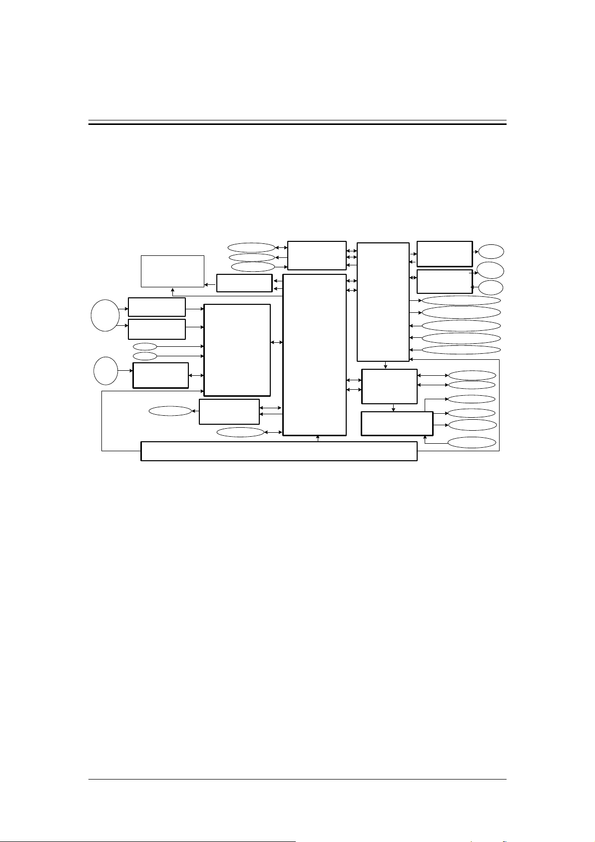
4 Hardware System
According to function modules classification, the entire hardware system can be divided into
main board, signal processing board, driver board, touch screen control board, interface board,
indicator board, power board, pneumatic control board, pre-amplification board, laser control
board, volumetric board, etc. See Figure 4-1 for the block diagram of the entire hardware
system:
Laser
Diode
Position
Sensor
TFT-LCD
Pre-amplification
Board(LAS)
(3100-30-41192)
Pre-amplification
Board(MAS)
(3100-30-41192)
Hole
Pool
Stop
(3100-30-41196)
Volumetric
Board
Touch Screen
5V&12V
RBC/PLT
HGB
BackLight
Inner Scanner
Step Motors
Position Sensors
Inverter
A/Ds
Signal Processing
Board
(3100-30-41196)
051-000192-00
GPIOs
Touch Screen
Control Board
051-000202-00
(3100-30-41206)
Hard Disk
Power Board
(3100-30-411881)
Samples Feeding
(3100-30-41204)
12V
GPIO
LVDS
DSPI
Main Board
(3100-30-41182)
051-000197-00
UART
5V
FLEX-BUS
Figure 4-1 Block diagram of the hardware system
See below for the voltage distribution flow chart:
Board
5V&12V
UART
GPIO
USB
TCP/IP
UART
GPIO
GPIO
5V
Driver Board
(3100-30-41186)
A/D
GPIO
051-000191-01
GPIO
Interface
Board
(3100-30-41200)
DB9
Pneumatic Control
Board
(3100-30-41201)
5V&12V&24V
Laser Control Board
(3100-30-41194)
Indicator Board
(3100-30-41198)
USB
RJ45
Indicator
Step&DC Motors
Valves&Pumps
&Magnet&Heaters
Position&Liquid Sensors
Temperature Sensors
Gas Pressure
USB Devices
PC
Fan
Compressor
Indication LED
AC Power
Laser
Diode
Light
Sample
Key
4-1
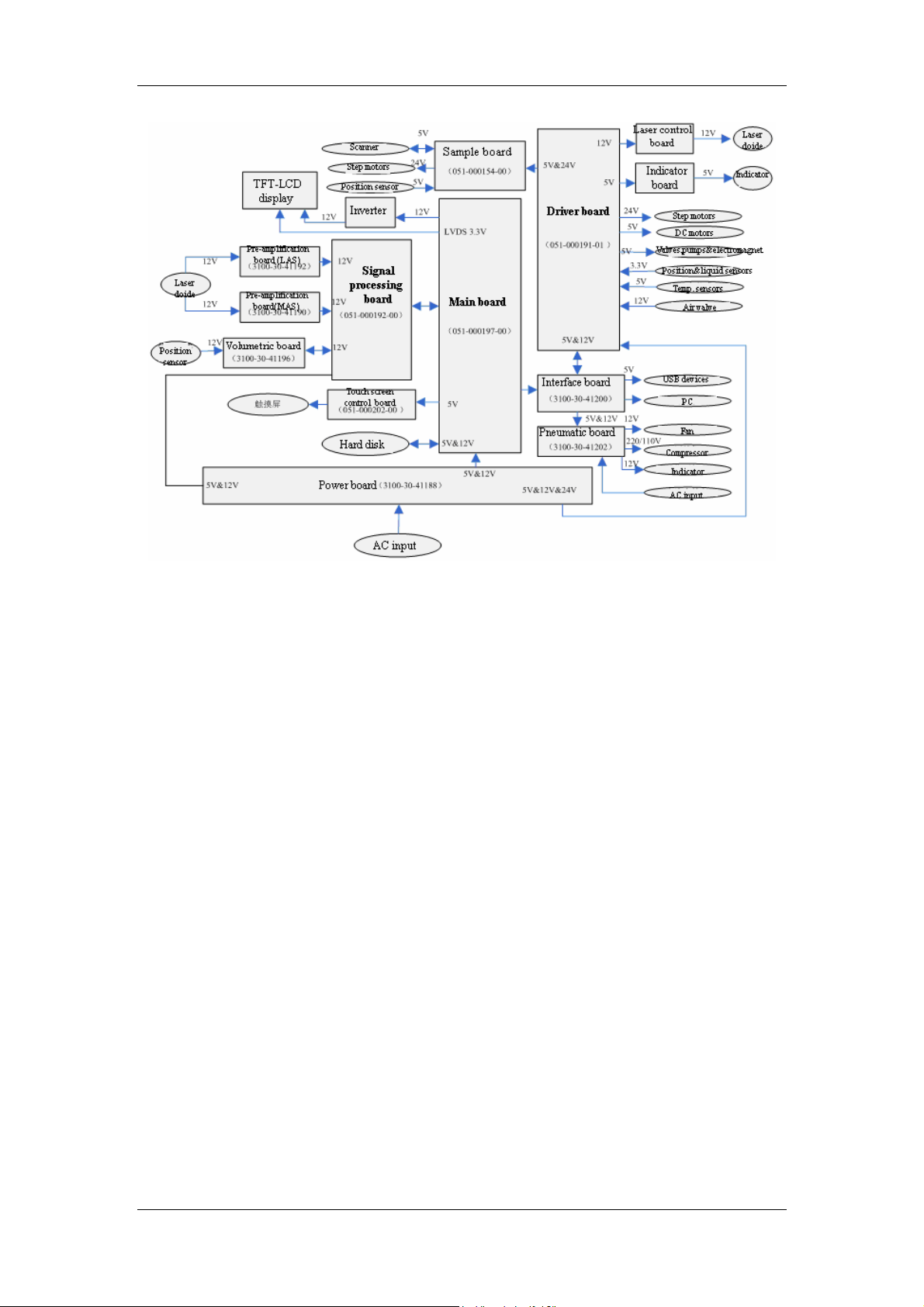
Hardware System
Figure 4-2 Voltage distribution flow chart
4-2

Hardware System
4.1 Main Board
4.1.1 Overview
In BC-5800 5-differential hematology analyzer, main board is the hardware platform of the
operation system and application software, it controls the operation of the whole system. It
offers some external interfaces, such as USB interface, TTL serial port, RS232 serial port, IDE
interface, network interface, SPI interface, difference display interface, etc.
Section 4.1 of this manual is the servicing and troubleshooting guideline of the main board.
4.1.2 Board Composition
Function
Provides platform for the operation system and application software;
Realizes centralized management and overall coordination over all function boards.
Two RS232 serial ports and two TTL level serial ports;One LVDS level display
interface/one TFT LCD backlight interface;
One speed SPI interface with bit rate over 20Mbps;
One standard IDE data interface/one IDE hard disk power interface;
Four USB interfaces, meeting USB standard;
One 10/100Mbps network interface;
One BDM interface;
One JTAG interface of the FPGA;
One configured interface of the EPCS1.
See below Figure 4-3 for the block diagram of the main board:
4-3
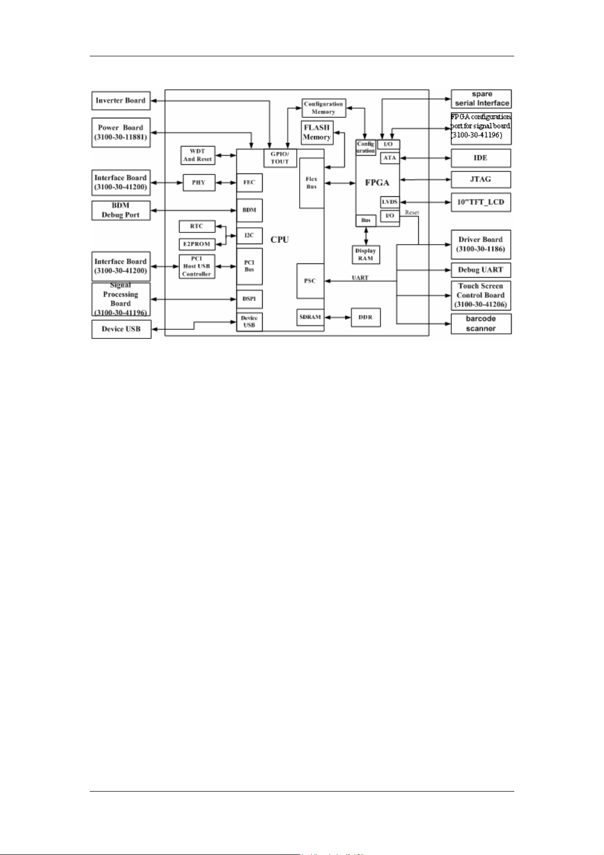
Hardware System
Figure 4-3 Block diagram of the main board
Description
Provides platform for the operation system and application software;
CPU: MCF5474, running frequency is 266MHZ;
DDR: 128M, running frequency is 133MHZ;
FLASH: no less than 8M BYTE (storing initialization program and operation system)
IDE: no less than 40G;
Realizes centralized management and overall coordination over all function boards.
Sends commands to signal processing board through SPI interface and receives responses
and sampling information from the signal processing board simultaneously;
Sends control commands to driver board through serial port and receives responses from the
driver board simultaneously;
The main board can upgrades the hardware of signal processing board and driver board
respectively through serial port and GPIO interface;
Two TTL level serial ports and two RS232 serial ports;
The main board communicates with the driver board through TTL level serial port, sends
control commands to the driver board and receives its responses. Its communication
parameters are:
Baud rate: 38400bps
Data bit: 8 bits
Stop bit: 1bit
Start bit: 1bit
Verification mode: even parity check
4-4

Hardware System
The other TTL level serial port is reserved
The main board receives touch information from the touch screen through a RS232 serial port,
the communication parameters are:
Baud rate: 19200/38400bps (depending on the control board of the touch screen)
Data bit: 8 bits
Stop bit: 1bit
Start bit: 1bit
Verification mode: none
One serial port on the main board is led to the interface board to get connected with external
barcode reader. The communication parameters depend on the external barcode reader.
One LVDS level display interface/one TFT LCD backlight interface
Connects the 10.4-inch TFT LCD
One speed SPI interface with bit rate over 20Mbps
Communicates with and sends control commands to the signal processing board, and receive
its responses and sampling information simultaneously.
One standard IDE data interface/one IDE hard disk power interface
Connects the hard disk of the IDE interface. It supports 40G capacity and PIO mode. DMA
mode is not supported.
Four USB interfaces, meeting USB standard
Connected to the backboard of the analyzer enclosure from the interface board, the USB
interfaces connect the USB mouse, keyboard, barcode reader and memory (USB flash drive /
portable disk).
One 10/100Mbps network interface
Connected to the backboard of the analyzer enclosure from the interface board, the network
interface downloads program and uploads data.
One BDM interface
It is used when debugging main board for hardware examination, program downloading and
FLASH programming. It is not open to users.
One JTAG interface of the FPGA
It is used for FPGA debugging, not open to users.
One configured interface of the EPCS1
It is used for FPGA program downloading.
Interface Definition
The main board has 18 external interfaces with their number from J1-J18. Among the
interfaces, J7 is not to be used; J15 and J18 are reserved interfaces. The positions of all
interfaces on the board are portrayed as below Figure 4-4
4-5
.
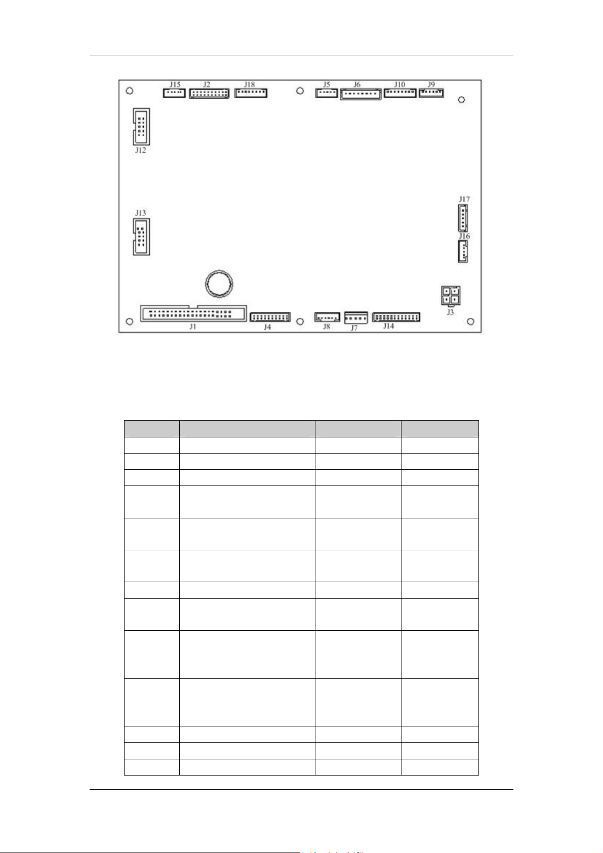
Hardware System
Figure 4-4 Interface layout of the main board
See Table 4-1 for the function of each interface.
Table 4-1 Interfaces on the main board
Interface Function Number of pins Description
J1 IDE interface 40 /
J2 LCD data wire interface 20 /
J3 Power interface 4 /
J4
J5
J6
J7 Device USB interface 5 Not to be used
J8
J9
J10
J11 BDM interface of CPU 26 /
J12 JTAG interface of the FPGA 10 /
J13 EPCS1 configuration 10 /
Interface to signal
processing board
Communication serial port
2 (connects to driver board)
Communication serial port
3 (spare)
Network interface to
interface board
Communication serial port
0 (connects to barcode
reader)
Communication serial port
1 (connects to touch screen
controller)
20
5
8
6
6
8
/
TTL level
TTL level
RS232 level
RS232 level
4-6
interface
J14
J15
J16 LCD backlight interface 5 /
J17 IDE power interface 5 /
J18 Spare I/O interface 8 /
USB interface to interface
board
Spare communication serial
port
Definition of pins in J1 interface
Hardware System
24
5
/
RS232 level
J1 is a standard IDE interface; see
PIN
No.
1 nRESET Reset 21 NA Reserved
2 GND Signal ground 22 GND Signal ground
3 DD7 Data bit 7 23 nDIOW Write signal
4 DD8 Data bit 8 24 GND Signal ground
5 DD6 Data bit 6 25 nDIOR Read signal
6 DD9 Data bit 9 26 GND Signal ground
7 DD5 Data bit 5 27 NA Reserved
8 DD10 Data bit 10 28 GND Signal ground
9 DD4 Data bit 4 29 NA Reserve
10 DD11 Data bit 11 30 GND Signal ground
11 DD3 Data bit 3 31 INTRQ Interrupt request
12 DD12 Data bit 12 32 NA Reserved
13 DD2 Data bit 2 33 DA1 Register address 1
14 DD13 Data bit 13 34 NA Reserved
15 DD1 Data bit 1 35 DA0 Register address 0
16 DD14 Data bit 14 36 DA2 Register address 2
17 DD0 Data bit 0 37 nCS0 Chip selection 0
18 DD15 Data bit 15 38 nCS1 Chip selection 1
19 GND Signal ground 39 nDASP Sub-device effective
20 NA Reserved 40 GND Signal ground
Definition Function
Table 4-2 for the distribution and definition of its pins.
Table 4-2 Definition of J1
PIN
No.
Definition Function
Definition of pins in J2 interface
J2 is the LVDS interface connecting to LCD, it has 20 pins. See Table
Table 4-3 Definition of J2
PIN No. Mark Function PIN No. Mark Function
1 +3.3V Power supply 11 RxIN2+ LVDS receiving
4-7
4-3 for its definition.

Hardware System
2 +3.3V Power supply 12 RxIN2+ channel 2
3 GND Ground 13 GND Ground
4 GND Ground 14 CKINn+
5 RxIN0- 15 CKINn-
LVDS
LVDS clock
receiving
6 RxIN0+
channel 0
16 GND Ground
7 GND Ground 17 GND Ground
8 RxIN1+ 18 NC No contact
LVDS
receiving
9 RxIN1-
channel 1
19 NC No contact
10 GND Ground 20 NC No contact
Definition of pins in J3 interface
J3 interface is the power input port of the entire main board. It provides +5V and +12V power
supply, see Table 4-4 for its pin distribution.
Table 4-4 Definition of J3
PIN No. Mark Function
1 VCC +5V power supply
2 P12V0 +12V power supply
3
4
GND Reference ground of +5V
power supply
PGND Reference ground of +12V
power supply
Definition of pins in J4 interface
J4 interface is the external communication interface connecting the signal processing board.
See Table 4-5 for its definition.
Table 4-5 Definition of J4
PIN
PIN No. Definition Function
No. Definition Function
1 SPIOUT Data wire 11 DSCK Clock
2 GND
Reference
ground 12 GND
Reference
ground
Configuration
3 SPISCK Clock 13 CONF_DONE
completes
4 SPIIN Data wire 14 NA Reserved
SPI chip
5 SPICS0
selection 0 15 nCONFIG Configuration
Reference
6 GND
ground 16 nCE Enable
4-8

Hardware System
7 NA Reserved 17 DATA0 Data
Chip
8 NA Reserved 18 nCS0
selection
Configure to
9 CONFIG_ENA
enable 19 ADS0 Data
Reference
10 NA Reserved 20 GND
ground
Definition of pins in J5 interface
J5 interface is the COM port 2 external interface connecting the driver board. See Table 4-6 for
definition of its pins.
Table 4-6 Definition of J5
Signal wire Definition Function I/O relation
1 TXD2 Sending data wire OUT
2 RXD2 Receiving data wire IN
3 GND Reference ground
-
4 ISP_PSEN Selection wire OUT
5 ISP_RST Reset wire OUT
Definition of pins in J6 interface
J6 interface is reserved temporarily. See Table 4-7 for the definition of its pins.
Table 4-7 Definition of J6
PIN No. Definition Function I/O relation
Reference
1 GND
ground
12V power
2 12P0
supply
+5V power
3 +5V0
supply
Sending data
4 TXD3
wire
Reference
5 GND
ground
Receiving data
6 RXD3
wire
Reference
7 GND
ground
Reference
8 GND
ground
-
OUT
OUT
OUT
-
IN
-
-
4-9

Hardware System
Definition of pins in J7 interface
J7 interface in not used in practice.
Definition of pins in J8 interface
J8 interface the external network interface that is connected to the interface board. See Table
4-8 for its definition.
Table 4-8 Definition of J8
Serial No. Definition Function I/O relation
1 ET_TP+
2 ET_TP-
3 ET_RP+
4 ET_RP-
5 ET-NGR
6 PWFBOUT USB power supply OUT
Positive end of
sending
Negative end of
sending
Positive end of
receiving
Negative end of
receiving
Virtual earth of
receiving
OUT
OUT
IN
IN
-
Definition of pins in J9 interface
J9 interface is the COM port 0 external interface connecting the barcode reader. See Table 4-9
for definition of its pins.
Table 4-9 Definition of J9
Pin Definition Function Pin Definition Function
Sending data
1 TXD2
2 RXD2
3 CTS
Definition of pins in J10 interface
J10 interface is the COM port 1 external interface connecting the touchscreen controller. See
4-10 for definition of its pins.
Table
wire 4 RTS
Receiving
data wire 5 GND
Cancel
transmission 6 +5V0 Power supply
Request
transmission
Reference
ground
4-10

Hardware System
Table 4-10 Definition of J10
PIN No. Definition Function I/O relation
1 TXD4
2 RXD4
3 CTS
4 RTS
5 GND
Sending data
wire
Receiving data
wire
Cancel
transmission
Request
transmission
Reference
ground
OUT
IN
IN
OUT
-
6 +5V0 Power supply OUT
7 NA Reserved /
8 NA Reserved /
Definition of pins in J11 interface
J11 interface is the BDM interface of CPU; it is not open to customers.
Definition of pins in J12 interface
J12 interface is the JTAG interface of the FPGA; it is not open to customers.
Definition of pins in J13 interface
J11 interface is the configured interface of the EPCS1; it is not open to customers.
Definition of pins in J14 interface
J14 interface is the USB interface connecting the interface board. See Table4-11 for the
distribution of its pins.
Table4-1 1 Definition of J14
PIN
No.
1
2
3
4
5
Definition Function
NA Reserved
NA Reserved
NA Reserved
NA Reserved
DM4 Data negative
(port 4)
PIN
No.
13
14
15
16
17
Definition Function
GND Reference
ground
GND Reference
ground
GND Reference
ground
DP2 Data positive
(port 2)
GND Reference
ground
4-11

Hardware System
6
7
8
9
10
11
12
GND Reference
ground
DP4 Data positive
(port 4)
VBUS3 Port 3 input
power supply
VBUS4 Port 4 input
power supply
DP3 Data positive
(port 3)
GND Reference
ground
DM3 Data negative
(port 3)
18
19
20
21
22
23
24
DM2 Data negative
GND Reference
VBUS2 Port 2 input
VBUS1 Port 1 input
GND Reference
DM1 Data negative
DP1 Data positive
Definition of pins in J15 interface
J15 interface is a spare serial port; it is not to be used temporarily.
Definition of pins in J16 interface
(port 2)
ground
power supply
power supply
ground
(port 1)
(port 1)
J16 interface is LCD backlight interface. See Table 4-12 for the distribution of its pins.
Table 4-12 Definition of J16
PIN No. Definition Function
1 12V +12V power supply
2
PGNA Reference ground of +12V
power supply
3 ENABLE LCD backlight enabling signal
4 VBRT LCD brightness control signal
5 NA Reserved
Definition of pins in J17 interface
J17 is the power interface of IDE device. See Table 4-13 for the distribution of its pin.
Table 4-13 Definition of J17
PIN No. Definition Function
1 +12P0 +12V power supply
2 Ground
3 Ground
Reference ground of
+12V power supply
Reference ground of
+5V power supply
4 +5V0 +5V power supply
Definition of pins in J18 interface
4-12

Hardware System
J18 is the external spare I/O interface; it is not to be used temporarily.
Assembly drawing
See Figure 4-5 for the assembly drawing of the main board.
Figure 4-5 Assembly drawing of the main board
4-13

Hardware System
4.1.3 Adjustment and Test Points
LED Function Definition
Table 4-14 Function definition of main board LED
Indicator Function
D2 Reserved temporarily.
D3 +5V power indicator, lights up when power is on
D4 IDE device effectiveness indicator, lights up when the device
is in effect.
D7 Network full duplex communication indicator, lights up when
it is in effect.
D8 Network Collision indicator, lights up when it is in effect.
D9 Activating 100M network communication indicator, lights up
when it is in effect.
D10 Network connection indicator, lights up when it is in effect.
D11 Activating 10M network communication indicator, lights up
when it is in effect.
D12 Power indicator of the second USB port, lights up when
power is on.
D13 Power indicator of the fourth USB port, lights up when power
is on.
D14 Power indicator of the third USB port, lights up when power
is on.
D15 Power indicator of the first USB port, lights up when power is
on.
D16 Reserved for software use.
D17 Reserved for now.
D18 Reserved for software use.
D19 Reserved for now.
D20 FPGA configuration completion indicator, lights up when
configuration completes.
D21 Reserved for software use.
Function Definition of Test Points
Table 4-15 Test point functions
Test Point Tested Signal Function
TP1 DDR_VREF DDR SRAM reference voltage
TP2 DDR_VTT DDR SRAM termination voltage.
TP3 VDD +3.3V power supply voltage.
TP4 VCC +5.0V power supply voltage.
4-14

Hardware System
TP5 VCCINT FPGA kernel operating voltage
TP6 IRQ2 Interrupt signal 2.
TP7 IRQ3 Interrupt signal 3.
TP8 F_PLLVDD FPGA phase-lock loop voltage
TP9 2V5 +2.5V power supply voltage.
TP10 MCF_BWE1 BYTE selection signal 1.
TP11 MCF_BWE2 BYTE selection signal 2.
TP12 FB_CS0 FlexBus chip selection signal 0.
TP13 MCF_TA Transmit response signal.
TP14 MCF_OE Output enabling signal.
TP15 IRQ5 Interrupt signal 5.
TP16 ISP1561_CLK Input clock of the ISP1561
TP17 FB_CS1 FlexBus chip selection signal 1.
TP18 MCF_BWE0 BYTE selection signal 0.
TP19 MCF_BWE3 BYTE selection signal 3.
TP20 FB_CS2 FlexBus chip selection signal 2.
TP21 Not to be used /
TP22 MCF_TS Address latching signal.
TP23 CLKIN CPU input clock.
TP24 CPURSTI CPU reset signal
TP25 / ISP1561 interrupt signal 1.
TP26 / ISP1561 interrupt signal 12.
TP27 / ISP1561 signal SM1.
TP28 / ISP1561 signal A20OUT.
TP29 / ISP1561 signal PME.
TP30 MCF_RW FlexBus read and write signal.
TP31 Not to be used /
TP32 LCD_CLK Input clock in FPGA for LCD.
TP33 FPGA_CLK Input clock for FPGA operation
TP34 Not to be used /
TP35 L_CLK SN75LVDS83 input clock.
TP36 PGND Reference ground of +12V voltage.
TP37
TP38
TP39
TP40
S_WE Write enabling input signal of display
memory.
S_CKE Clock enabling input signal of display
memory.
S_OE Output enabling signal of display
memory.
S_CE Display memory chip selection signal
1.
TP41 S_CLK Display memory input clock.
TP42 S_BWA BYTE input signal.
TP43 GND Signal ground.
4-15

Hardware System
TP44 GND Signal ground.
TP45 GND Signal ground.
TP46 GND Signal ground.
TP47 GND Signal ground.
TP48 GND Signal ground.
TP49 GND Signal ground.
Key Definition
Table 4-16 Key Definition
Mark Function
S1 System manual reset
4.1.4 Replacement and Connection
Purpose
The main board is a critical part in the whole device. When board failure occurs due to various
reasons, the board needs to be replaced and repaired in time to ensure the normal operation
of the device. Please replace the main board according to below procedure.
Tool
107 cross-headed screwdriver
Disassembling
Disassembling and mounting main board is quite easy. After taking off the wires connected to it,
its front look is shown as Figure 4-4. See Figure 4-6 for disassembling and mounting of main
board.
z Please make sure power is off and the power cord is disconnected when
mounting and disassembling boards.
z Please also wear antistatic gloves when repairing and disassembling
boards.
4-16

Hardware System
Figure 4-6 Main board disassembling and mounting-2
1---Main board shielding cover 3---Cross-recessed panhead screw M3x6
(with lock washer)
2---Main board, signal processing
board support stand
4---Main board
Installation
Installation is the opposite operation of disassembling.
Verification
1 After powering on the device, D3 and D20 turn on;
2 After system initialization, indicator D12, D13, D14 and D15 turn on;
4-17
Hardware System
3 The display screen displays normally;
4 The mouse in the touch screen can be operated normally.
4.1.5 Troubleshooting
Table 4-17 below lists all common errors of the main board and their resolving methods from
hardware perspective. Software errors are excluded. But a lot of errors need to be checked
with software. Errors caused by CPU damage are not listed in Table 4-17.
Table 4-17 Main board error analysis and processing
Serial
No.
1 System cannot start up
2 Blank screen
3
Phenomenon Error analysis and processing
Screen blur and color
cast
1 Possible causes of the error: input power failure,
including power cords not well-connected,
3.3V/2.5V/1.5V/1.25V power supply voltage
abnormity, etc.; FLASH chip failure, operation system
cannot be imported into DDR SDRAM where it
operates; DDR SDRAM chip failure, the operation
system cannot run normally; system main clock
(CLKIN) abnormity.
2 Recommended action: press reset button to restart
the system, see whether the same error still exists;
check to see whether the power indicator D3 is on, or
measure input voltage with a multimeter to see
whether the input voltage is within normal range;
check whether the fuse F1 and F2 are burnt out;
Check whether the voltages of 3.3V/2.5V/1.5V/1.25V
power supply are within their normal operating range
with a multimeter; check whether the main clock
works normally with an oscilloscope; examine FLASH
or DDR with test software (Note: When testing
FLASH, the programs in it will be wiped off. Use this
method with extreme care.)
1 Possible causes of the error: +12V power supply
does not supply power normally; the inverter is not
well connected; the enabling signal of pin 3 in J16
interface is low level (backlight on when the signal is
high level); FPGA does not return to original position
(system cannot start up); inverter failure, etc.
2 Recommended action: check with a multimeter and
oscilloscope.
1 Possible causes of the error: data wire is not well
connected; crystal oscillator X1/X6 does not work
normally; FPAG configuration failure (indicator D20 is
4-18

4
5
6
7
8
9
Hardware System
off); FPGA failure; chip U9 and U4 fail.
2 Recommended action: observe or check with a
multimeter or oscilloscope.
1 Possible causes for the error: poor contact;
Abnormal UART
communication
conversion chip U16/U17/U18 failure; UART of the
CPU fails.
2 Recommended action: observe or check with an
oscilloscope.
1 Possible causes of the error: interface board failure;
input clock (TP16:ISP1561_CLK) abnormity; Clock
X5 (12MHZ) abnormity; U24/U25 failure.
USB device cannot be
recognized
2 Recommended action: when solving the error,
please be observant. If short circuit occurs in the
interface board or over current happens due to other
reasons, indicators D12/D13/D14/D15 will turn off;
under other conditions, an oscilloscope can be used
for examination.
Possible causes of the error and the recommended
The clock does not
display normally, or
2005-1-1 is displayed
when the analyzer starts
up
action: If the clock does not display normally or
accurately, check whether the RTC clock X3 is
working normally or replace U22 and then perform
checking; If 2005-1-1 is displayed when starting up,
check to see whether the batteries are in good contact
or are running down.
1 Possible causes of the error: the connection cords
are not well connected; the drive chip U34 fails; the
SPI communication
failure
SPI module of the CPU fails.
2 Recommended action: there are a few components
in SPI communication unit, so connections cords and
the drive chip U34 need to be check for abnormity
when error occurs.
1 Data wires or power cords are not connected or in
poor contact; error occurs to FPGA chip (configuration
fails, or the chip itself fails);
2 Recommended action: observe or check with a
IDE device does not
operate normally
multimeter to see whether the wires are in good
contact; see if D20 is on to judge whether the FPGA
configuration is successful; If the results are
error-free, that is to say FPGA has been reset; if
FPGA or the drive chip are suspected to be in trouble,
replace the related chip and then perform checking.
Abnormal network
communication
1 Possible causes of the error: connection wires are
not well connected; the interface board fails; crystal
oscillator X2 does not work normally; network chip
4-19

Hardware System
U21 fails;
2 Recommended action: check whether the wires are
well connected and the interface board works
normally; check whether clock X2 is functioning with
an oscilloscope; examine network chip
U21(RTL8201);
Note: Generally errors occur in the network unit need
to be tested with software.
4-20

Hardware System
4.2 Signal Processing Board
4.2.1 Introduction
The signal processing board of BC-5800 auto hematology analyzer drives the sensors,
amplifies/filters/adjusts the primary signals of sensors and converts them into digital signal
pulses, which are then identified and stored. Moreover, this board monitors the operating
voltage, aperture voltage and WBC blank voltage (for detecting lamp installation and
cleanliness of the flow cell), and controls aperture zapping, consistent current source of
aperture electrode, drive current of HGB LED, digital pot, etc.
Section 4.2 of this manual is the servicing and troubleshooting guideline of the signal
processing board.
4.2.2 Board Composition
The signal processing board consists of the analog and digital parts. The analog part includes
the power supply, WBC/RBC/HGB signal channels and power monitoring channel. The digital
part deals with FPGA and its interface connection, and pulse signal identification.
Function
Amplifying and collecting (LAS,MAS) WBC signals
Amplifying and collecting RBC/PLT signals
Detecting and collecting HGB signal
Identifying Pulse signal
Storing cell information
Controlling each analog channel and configuring signal amplification
Communicating with SPI
Monitoring voltage (operating voltage, WBC/HGB blank voltage and RBC aperture
voltage)
Zapping the aperture
See below Figure 4-7 for the block diagram of the signal processing board:
4-21
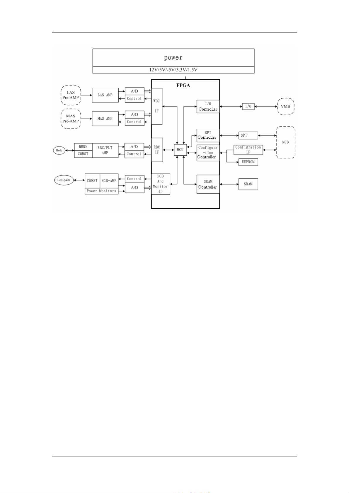
Hardware System
Figure 4-7 Block diagram of the signal processing board
Description
Amplifying and collecting (LAS,MAS) WBC signals
The signal processing board first eliminates DC components from the WBC signals coming
from the pre-amplification board, and then amplifies, filters, buffers the signals, which are then
converted to digital signals, and sent to the FPGA for pulse identification.
Amplifying and collecting RBC/PLT signals
The signal processing board amplifies (low noise, 2nd level and gain), buffers and A/D
converts the RBC signals, and then input the digital signals to FPGA for pulse identification.
Detecting and collecting HGB signal
The signal processing board converts the current signals of the HGB reaction bath to voltage
signals, then amplifies and converts the voltage signals to digital signals, which are then input
to the FPGA for inquiry of the main board.
Identifying pulse signals and storing cell information
While converting analog signals to digital signals, the FPGA identifies pulse signals and stores
the identified cell signal peaks in the SRAM.
Controlling each analog channel and configuring signal amplification
Through the I/O interface of FPGA, the signal processing board controls several switches
(including consistent current source switch, zapping voltage switch, consistent current
source/zapping switch and HGB LED switch) and the volumetric board, and configures the
4-22

Hardware System
amplification of the WBC/RBC/PLT/HGB channels as required.
Communicating with SPI
Through the SPI interface, the main board can control the signal processing board and
sampling, set/search for parameters, read data, etc.
Monitoring voltage
The signal processing board monitors the operating voltage, WBC/HGB blank voltage and
RBC aperture voltage through the shared A/D with the HGB board.
Zapping the aperture
When the analyzer runs for a specific period of time or the RBC bath is blocked by foreign
matters, the signal processing board can zap the aperture, removing the dirty and foreign
matters.
Interface Definition
There are 8 interfaces on the signal processing board, which are LAS, MAS, RBC/PLT, HGB,
POWER, JTAG, VMB and MCB, as shown in Figure 4-8.
4-23

Hardware System
Figure 4-8 Interface layout of the signal processing board
See Table 4-18 for the function of each interface.
Table 4-18 Interfaces on the signal processing board
Interface Function Number of pins Description
J1
J2
J3
Powers the lower pre-amplification board
and introduces its signals
Powers the upper pre-amplification
board and introduces its signals
Drives LEDs with constant current and
introduces the light intensity signals
5
5
4
/
/
/
4-24

Hardware System
J4
Drives the aperture with constant current
and introduces the RBC/PLT pulse
3
/
signals
J5
J6
For SPI communication and FPGA
downloading
Introduces the 5V and 12V power
supplies
20
6
/
/
J7 Not open to users 10 /
J8
Powers the volumetric board and
introduces its signals
6
/
J9 Not open to users 40 /
Definition of pins in J1 interface
J1 is a LAS signal interface; see Table 4-19 for the distribution and definition of its pins.
Table 4-19 LAS signal interface definition
Pin No. Name Description Signal Type
1 P12V +12V analog power supply +12V
2 AGND-W WBC analog ground /
3 AGND-W WBC analog ground /
4 LAS LAS signal ANALOG
5 AGND-W WBC analog ground /
Definition of pins in J2 interface
J2 is a MAS signal interface; see Table 4-20 for the distribution and definition of its pins.
Table 4-20MAS signal interface definition
Pin No. Name Description Signal Type
1 P12V +12V power supply +12V
2 AGND-W WBC analog ground /
3 AGND-W WBC analog ground /
4 MAS MAS signal ANALOG
5 AGND-W WBC analog ground /
Definition of pins in J3 interface
J3 is a HGB signal interface; see Table 4-21 for the distribution and definition of its pins.
4-25

Hardware System
Table 4-21 HGB signal interface definition
Pin No. Name Description Signal Type
1 HGB+ Positive end of HGB-LED ANALOG
2 HGB- Negative end of HGB-LED ANALOG
3 HGBIN HGB signal input ANALOG
4 AGND Analog ground/shielding
/
ground
Definition of pins in J4 interface
J4 is a RBC/PLT signal interface; see Table 4-22 for the distribution and definition of its pins.
Table 4-22 RBC/PLT signal interface definition
Pin No. Name Description Signal Type
1 SHELL Shielding ground /
2 RBC RBC/PLT signals ANALOG
3 AGND-R RBC analog ground /
Definition of pins in J5 interface
J5 is an interface to the main board; see Table 4-23 for the distribution and definition of its pins.
Table 4-23 Main board signal interface definition
Pin No. Name Description Signal Type
1 SDI SPI data input LVTTL
2 GND Digital ground /
3 SCK SPI clock LVTTL
4 SDO SPI data output LVTTL
5 nCS SPI chip selection LVTTL
6 GND Digital ground /
7 N.C. Null /
8 N.C. Null /
9 nPRG Program enabling /
10 N.C. Null /
11 DCLK Clock LVTTL
12 GND Digital ground /
13 DONE Configuration completes LVTTL
14 VDD +3.3V digital power supply +3.3V
15 nCONFIG Start configuration LVTTL
16 nCE FPGA enabling LVTTL
17 DATA Configuration data output LVTTL
18 nCSO Configuration chip
LVTTL
selection
19 ASDI Configuration data input LVTTL
4-26

Hardware System
20 GND Digital ground /
Definition of pins in J6 interface
J6 is a power interface; see Table 4-24 for the distribution and definition of its pins.
Table 4-24 Power interface definition
Pin No. Name Description Signal Type
1 5A0 +5V power input +5V
2 5A0 +5V power input +5V
3 12A0 +12V power input +12V
4 AGND Analog ground /
5 AGND Analog ground /
6 AGND Analog ground /
Definition of pins in J7 interface
J7 is a JTAG debugging interface; see Table 4-25 for the distribution and definition of its pins.
Table 4-25 JTAG debugging interface definition
Pin No. Name Description Signal Type
1 TCK Clock LVTTL
2 GND Digital ground /
3 TDO Data output LVTTL
4 VDD +3.3V digital power supply +3.3V
5 TMS Mode selection LVTTL
6 VDD +3.3V digital power supply +3.3V
7 N.C. Null /
8 N.C. Null /
9 TDI Data input LVTTL
10 GND Digital ground /
Definition of pins in J8 interface
J8 is an interface to the volumetric board; see Table 4-26 for the distribution and definition of its
pins.
Table 4-26 Volumetric board interface definition
Pin No. Name Description Signal Type
1 P12V +12V analog power supply +12V
2 GND Digital ground /
3 RES1 Reserved
4 nSTART Start counting LVTTL
5 nSTOP Stop counting LVTTL
6 nVMBLED Optical coupler control LVTTL
4-27

Hardware System
Assembly Drawing
See Figure 4-9 for the assembly drawing of the signal processing board.
Figure 4-9 Assembly of the signal processing board
4-28
 Loading...