


Service Manual
V
V
V
Patient Monitors

Mindray® is a registered trademark of Shenzhen Mindray Bio-Medical Electronics Co., Ltd.
Filte rLine
Microstream
Nellcor
Oxiband
Durasensor
OxiMax
Oxisensor
Max-Fast
miniMediCO
LNCS
LNOP
Masimo SET
®
is a U.S. registered trademark of Oridion Medical Ltd.
®
is a U.S. registered trademark of Oridion Medical Ltd.
™
is a U.S. trademark of Nellcor Puritan Bennett Inc.
®
is a U.S. registered trademark of Nellcor Puritan Bennett Inc.
®
is a U.S. registered trademark of Nellcor Puritan Bennett Inc.
™
is a U.S. trademark of Nellcor Puritan Bennett Inc.
®
is a U.S. registered trademark of Nellcor Puritan Bennett Inc.
™
is a trademark of Nellcor Puritan Bennett Inc.
®
is a trademark or registered trademark of Oridion Medical Ltd.
2
®
is a U.S. registered trademark of Masimo Corp.
®
is a U.S. registered trademark of Masimo Corp.
®
is a U.S. registered trademark of Masimo Corp.
Panorama™ is a U.S. trademark of Mindray, Inc.
Hypervisor is a registered trademark of Shenzhen Mindray Bio-Medical Electronics Co., Ltd.
Copyright © Mindray DS USA, Inc., 2011. All rights reserved. Contents of this publication may not be reproduced in any
form without permission of Mindray DS USA, Inc.
046-001131-00 V Series Service Manual

Tab le of C on ten ts
Foreword .................................................................................................................................................................................................................................v
How to Use This Guide .......................................................................................................................................................................................................v
Passwords................................................................................................................................................................................................................................v
Warnings, Cautions and Notes........................................................................................................................................................................................v
Theory of Operation ...................................................................................................................................................1 - 1
Introduction .............................................................................................................................................................................................................................1 - 1
Connectors for Peripheral Devices and Indicators .....................................................................................................................................................1 - 2
Connectors for Peripheral Devices........................................................................................................................................................................1 - 2
Indicators........................................................................................................................................................................................................................1 - 8
Main Unit ...................................................................................................................................................................................................................................1 - 10
Input System .................................................................................................................................................................................................................1 - 11
Output System..............................................................................................................................................................................................................1 - 11
Processing and Communications System..........................................................................................................................................................1 - 12
Power Management System ...................................................................................................................................................................................1 - 12
Equipment Interface System...................................................................................................................................................................................1 - 14
Interface Requirements.............................................................................................................................................................................................1 - 15
Parameter Module ......................................................................................................................................................................................................1 - 15
Repair Information .....................................................................................................................................................2 - 1
Introduction .............................................................................................................................................................................................................................2 - 1
Safety Precautions..................................................................................................................................................................................................................2 - 1
Troubleshooting Guidelines...............................................................................................................................................................................................2 - 2
Special Tools Required .........................................................................................................................................................................................................2 - 2
Disassembly Instructions.....................................................................................................................................................................................................2 - 3
Disassembling V 12 (12.1" Monitor)......................................................................................................................................................................2 - 4
Removal of the Battery Door...................................................................................................................................................................................2 - 5
Removal of the Front Housing................................................................................................................................................................................2 - 6
Removal of the Back Housing .................................................................................................................................................................................2 - 11
Disassembling V 21 (21.3" Monitor)......................................................................................................................................................................2 - 19
Disassembling V Dock ...............................................................................................................................................................................................2 - 34
Disassembling V Hub .................................................................................................................................................................................................2 - 38
Disassembling VPS Module .....................................................................................................................................................................................2 - 41
Disassembling CO
Disassembling 1X Module........................................................................................................................................................................................2 - 54
Disassembling Recoder Module ............................................................................................................................................................................2 - 58
Disassembling 12-Lead ECG Module ...................................................................................................................................................................2 - 61
Cable Wiring Diagrams.........................................................................................................................................................................................................2 - 63
Nurse Call Cable (3 Pin Circular to Unterminated) ..........................................................................................................................................2 - 63
Defib Synch Cable.......................................................................................................................................................................................................2 - 64
Serial Port to Serial Port Cable................................................................................................................................................................................2 - 64
ECG Shielded Lead Wires..........................................................................................................................................................................................2 - 65
3/5 Lead ECG Leadset ....................................................................................................................................................................................2 - 65
6-Lead ECG Leadset ........................................................................................................................................................................................2 - 69
Extension Lead ECG Leadset .......................................................................................................................................................................2 - 71
ECG Cable ESIS and Non ESIS..................................................................................................................................................................................2 - 73
3/5-Lead ECG Cable ........................................................................................................................................................................................2 - 73
6-Lead ECG Cable ............................................................................................................................................................................................2 - 74
Neonatal ECG Cable ........................................................................................................................................................................................2 - 76
IBP Cable.........................................................................................................................................................................................................................2 - 77
Temperature Cable.....................................................................................................................................................................................................2 - 78
IABP SYNC Cable..........................................................................................................................................................................................................2 - 81
Service Diagnostics Cable ........................................................................................................................................................................................2 - 81
Powered USB Cable ....................................................................................................................................................................................................2 - 82
Module.....................................................................................................................................................................................2 - 51
2
V Series Service Manual 046-001131-00 i

Table of Contents
Troubleshooting.....................................................................................................................................................................................................................2 - 83
ECG Troubleshooting.................................................................................................................................................................................................2 - 83
Temperature Troubleshooting...............................................................................................................................................................................2 - 85
Resp Troubleshooting ...............................................................................................................................................................................................2 - 85
IBP Troubleshooting...................................................................................................................................................................................................2 - 86
NIBP Troubleshooting................................................................................................................................................................................................2 - 87
Troubleshooting...............................................................................................................................................................................................2 - 88
SpO
2
Power Supply Troubleshooting .............................................................................................................................................................................2 - 89
Power On/Off Troubleshooting..............................................................................................................................................................................2 - 90
Display Failure Troubleshooting............................................................................................................................................................................2 - 91
V Hub Failure Troubleshooting ..............................................................................................................................................................................2 - 92
V Hub - External V Hub Troubleshooting ................................................................................................................................................2 - 92
Integral V Hub Troubleshooting ................................................................................................................................................................2 - 93
Alarm Troubleshooting.............................................................................................................................................................................................2 - 94
Recorder Troubleshooting.......................................................................................................................................................................................2 - 94
Interface Failure Troubleshooting.........................................................................................................................................................................2 - 95
USB Troubleshooting.................................................................................................................................................................................................2 - 95
Network-Related Problem Troubleshooting.....................................................................................................................................................2 - 96
Software Upgrade Troubleshooting.....................................................................................................................................................................2 - 97
Block Diagrams ...........................................................................................................................................................3 - 1
Introduction .............................................................................................................................................................................................................................3 - 1
Block Diagram..........................................................................................................................................................................................................................3 - 2
Isometric Drawings and Parts List.............................................................................................................................4 - 1
Introduction .............................................................................................................................................................................................................................4 - 1
V Dock Assembly (P/N 0998-00-1801-01)......................................................................................................................................................................4 - 1
AC-DC Power Module (P/N 801-DA6K-00032-00)............................................................................................................................................4 - 4
Subassembly, 12.1" Monitor (P/N 0998-00-1800-101)..............................................................................................................................................4 - 5
Subassembly, Back, 12.1" Monitor (P/N 0997-00-0607-01)..........................................................................................................................4 - 6
Subassembly, Chassis, 12.1" Monitor (P/N 801-DA6K-00023-00)...............................................................................................................4 - 8
Subassembly, Front, 12.1" Monitor (P/N 801-DA6K-00117-00)..................................................................................................................4 - 9
Subassembly, 21.3" Monitor (P/N 0998-00-1800-201)..............................................................................................................................................4 - 10
Subassembly, Back, 21.3" Monitor (P/N 0997-00-0614-01)..........................................................................................................................4 - 11
Subassembly, Chassis, 21.3" Monitor (P/N 801-DA6K-00024-00)...............................................................................................................4 - 12
Subassembly, Front, 21.3" Monitor (P/N 801-DA6K-00118-00)..................................................................................................................4 - 13
V Hub Assembly (P/N 0998-00-1803-01)........................................................................................................................................................................4 - 14
Assembly, Masimo VPS Module (P/N 0998-00-1802-0101A)..................................................................................................................................4 - 15
Subassembly, Valve, Pneumatic (P/N 801-DA6K-00066-00)........................................................................................................................4 - 16
Subassembly, VPS Front End (P/N 0997-00-0611-01) ....................................................................................................................................4 - 1
Subassembly, Front, 3X Module (P/N 0997-00-0612-03)..............................................................................................................................4 - 18
Assembly, Nellcor VPS Module (P/N 0998-00-1802-0102A)....................................................................................................................................4 -
Assembly, Recorder, Module (P/N 0998-00-1802-0202A).......................................................................................................................................4 - 2
Assembly, CO
Module (P/N 0998-00-1802-0301A)..................................................................................................................................................4 - 21
2
Assembly, Temperature Module (P/N 0998-00-1802-0501A)................................................................................................................................4 - 2
Assembly, IBP Module (P/N 0998-00-1802-0401A)....................................................................................................................................................4 - 2
Subassembly, Cardiac Output (C.O.) Module (P/N 0998-00-1802-0701A).........................................................................................................4 - 2
Assembly, VDI, Module (P/N 0998-00-1802-0801A) ..................................................................................................................................................4 - 2
Subassembly, Module, ECG, 12 Lead (P/N 0998-00-1804-01/0998-00-1804-02) ............................................................................................4 - 26
Diagnostics and Calibration.......................................................................................................................................5 - 1
Introduction .............................................................................................................................................................................................................................5 - 1
Warnings and Guidelines ....................................................................................................................................................................................................5 - 1
System Setup ...........................................................................................................................................................................................................................5 - 2
Introduction...................................................................................................................................................................................................................5 - 2
7
19
0
2
3
4
5
ii 046-001131-00 V Series Service Manual

Tab le of C on ten ts
System Dialog...............................................................................................................................................................................................................5 - 2
Navigating to the System Dialog ...............................................................................................................................................................5 - 2
Configuring the General Tab .......................................................................................................................................................................5 - 3
Configuring the Quick Functions Tab ......................................................................................................................................................5 - 3
Configuring the Alarms Tab .........................................................................................................................................................................5 - 5
Configuring the Printer Tab .........................................................................................................................................................................5 - 7
Configuring the Network Tab .....................................................................................................................................................................5 - 8
Configuring the System Tab ........................................................................................................................................................................5 - 9
Changing Password ........................................................................................................................................................................................5 - 12
Changing Password to Access Service Menu ........................................................................................................................................5 - 14
Configuration Management....................................................................................................................................................................................5 - 14
System Information Page....................................................................................................................................................................................................5 - 15
NIBP Calibration......................................................................................................................................................................................................................5 - 16
®
Microstream
Microstream
CO2 Calibration ..........................................................................................................................................................................................5 - 18
®
CO2 Leakage Test ......................................................................................................................................................................................5 - 19
Touchscreen Calibration......................................................................................................................................................................................................5 - 20
Verification................................................................................................................................................................................................................................5 - 21
Initial Setup....................................................................................................................................................................................................................5 - 21
V 12 Monitor Only ............................................................................................................................................................................................5 - 21
V 12 Monitor with V Hub ...............................................................................................................................................................................5 - 21
First Turn On ......................................................................................................................................................................................................5 - 21
ECG Tests ........................................................................................................................................................................................................................5 - 22
Initialization .......................................................................................................................................................................................................5 - 22
Leads Off .............................................................................................................................................................................................................5 - 22
Pacer Detect ......................................................................................................................................................................................................5 - 22
Heart Rate ...........................................................................................................................................................................................................5 - 22
Alarms ..................................................................................................................................................................................................................5 - 22
IBP 1 and IBP 2 Verification ......................................................................................................................................................................................5 - 23
Temperature Verification..........................................................................................................................................................................................5 - 23
Verification .........................................................................................................................................................................................................5 - 23
SpO
2
NIBP Verification ..........................................................................................................................................................................................................5 - 24
RESP Verification..........................................................................................................................................................................................................5 - 24
C.O. Verification ..........................................................................................................................................................................................................5 - 24
Operation Verification ......................................................................................................................................................................................5 - 25
CO
2
Battery Operation Verification................................................................................................................................................................................5 - 25
Network Print Test.......................................................................................................................................................................................................5 - 26
VDI Test ...........................................................................................................................................................................................................................5 - 26
Recorder Test ................................................................................................................................................................................................................5 - 26
Electrical Safety Tests.................................................................................................................................................................................................5 - 27
Protective Earth Resistance ..........................................................................................................................................................................5 - 28
Earth Leakage Test ..........................................................................................................................................................................................5 - 29
Patient Leakage Current ...............................................................................................................................................................................5 - 30
Mains on Applied Part Leakage ..................................................................................................................................................................5 - 32
Patient Auxiliary Current ...............................................................................................................................................................................5 - 33
Maintenance ...............................................................................................................................................................6 - 1
User Maintenance Introduction........................................................................................................................................................................................6 - 1
Maintenance Schedule.........................................................................................................................................................................................................6 - 2
Mechanical/Physical/Visual Inspection...............................................................................................................................................................6 - 3
Perform NIBP Verification and Calibration .........................................................................................................................................................6 - 3
Perform CO
Perform ECG Verification ..........................................................................................................................................................................................6 - 3
Perform RESP Verification.........................................................................................................................................................................................6 - 3
Verification and Calibration...........................................................................................................................................................6 - 3
2
V Series Service Manual 046-001131-00 iii

Table of Contents
Perform IBP Verification ............................................................................................................................................................................................6 - 3
Perform SpO
Verification ........................................................................................................................................................................................6 - 3
2
Perform Temperature Verification ........................................................................................................................................................................6 - 3
Perform C.O. Verification ..........................................................................................................................................................................................6 - 4
Perform VDI Verification............................................................................................................................................................................................6 - 4
Perform Recorder Verification ................................................................................................................................................................................6 - 4
Perform Electrical Safety Tests................................................................................................................................................................................6 - 4
Perform Touchscreen Calibration..........................................................................................................................................................................6 - 4
Perform Battery Verification....................................................................................................................................................................................6 - 4
Perform Network Print Test .....................................................................................................................................................................................6 - 4
Care and Cleaning of the Monitor....................................................................................................................................................................................6 - 5
Decontamination of the Monitor .....................................................................................................................................................................................6 - 6
Care and Cleaning of SpO
Sensors.................................................................................................................................................................................6 - 6
2
Care and Cleaning of Reusable Temperature Probes ...............................................................................................................................................6 - 7
Cleaning CO
Sensors, Adapters and Sampling Components...............................................................................................................................6 - 7
2
Sterilization and Cleaning of Cuffs...................................................................................................................................................................................6 - 7
Reusable Cuffs with Bladders..................................................................................................................................................................................6 - 7
Disposable Blood Pressure Cuffs ...........................................................................................................................................................................6 - 8
Care and Cleaning of ECG Cables and Lead wires......................................................................................................................................................6 - 8
Battery Replacement and Maintenance.........................................................................................................................................................................6 - 9
Battery Replacement..................................................................................................................................................................................................6 - 9
Battery Maintenance..................................................................................................................................................................................................6 - 9
Serial Number of Li-ion Battery ..............................................................................................................................................................................6 - 9
Specification for Internal Battery Replacement (P/N 801-DA6K-00026-00)...........................................................................................6 - 10
Specification for Coin Battery on Carrier Board................................................................................................................................................6 - 10
Local Recorder Maintenance..............................................................................................................................................................................................6 - 10
Cleaning the Local Recorder Printhead...............................................................................................................................................................6 - 10
Local Recorder Paper Replacement......................................................................................................................................................................6 - 10
Care and Storage of Thermal Chart Paper..........................................................................................................................................................6 - 11
Installation Guide .......................................................................................................................................................7 - 1
Installing V Dock.....................................................................................................................................................................................................................7 - 1
Mounting V Dock to a Wall Mount...................................................................................................................................................................................7 - 2
Mounting V Dock to a Rolling Stand ..............................................................................................................................................................................7 - 5
Installing 12.1” Monitor/21.3” Monitor to V Dock.......................................................................................................................................................7 - 6
Installing V Hub.......................................................................................................................................................................................................................7 - 8
Warranty......................................................................................................................................................................8 - 1
Warranty Statements ............................................................................................................................................................................................................8 - 1
Phone Numbers and How To Get Assistance...............................................................................................................................................................8 - 2
Manufacturer's Responsibility ...........................................................................................................................................................................................8 - 2
iv 046-001131-00 V Series Service Manual

Foreword Introduction
Foreword
The V Series Service Manual is intended as a guide for technically qualified personnel during
repair and calibration procedures.
Unauthorized servicing may void the remainder of the warranty. Check with the factory or with a
local authorized representative to determine the warranty status of a particular instrument.
The V 12/V 21 operates on line voltages. Therefore, an electric shock hazard may exist when the
instrument covers are removed. Repair and calibration procedures should only be performed by
qualified personnel who proceed with care and follow proper servicing techniques. Warnings are
given in various chapters, as well as in other appropriate locations.
How to Use This Guide
This guide is divided into eight sections. Navigate through the table of contents at the left of the
screen to select the desired topic. Links to other relevant sections are also provided within the
individual topics. In addition, scrolling through the topics with the page up and page down keys
is also possible.
Passwords
A password may be required to access different modes within the monitor. The default
passwords are listed below:
Service Mode: SERVICE
System Setup: SYSTEM
Warnings, Cautions and Notes
Read and adhere to all of the warnings and cautions listed throughout this manual.
A WAR NIN G is provided to alert the user to potentially serious outcomes (death, injury or serious
adverse events) to the patient or the user.
A CAUTION is provided to alert the user that special care should be taken for the safe and
effective use of the device. They will include actions to be taken to avoid effects on patients or
users that will not be potentially life threatening or result in serious injury, but about which the
user should be aware.
A NOTE is provided when additional general information is available.
V Series Service Manual 046-001131-00 v

Introduction Warn ings, Cautions and No tes
This page intentionally left blank.
vi 046-001131-00 V Series Service Manual
1.0
Theory of Operation
1.1 Introduction
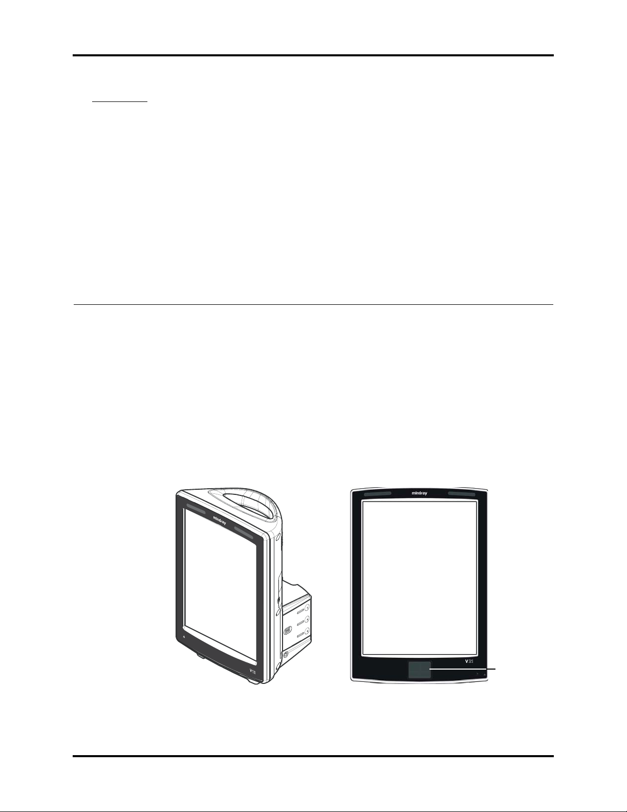
The V 12/V 21 is a modular patient monitoring system. The system architecture allows users to
customize, by removal or addition of modules, monitored parameters based on a patient’s
monitoring need or acuity level. The modular design simplifies the addition of monitoring
additional parameters with the addition of parameter modules.
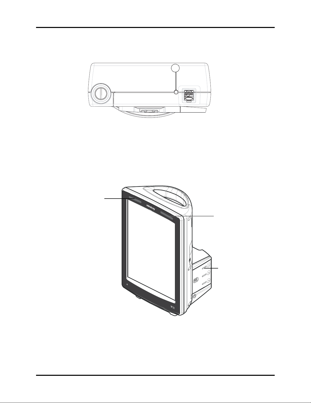
The V 12/V 21 focuses on the philosophy of “ Ease of Use” while incorporating traditionally
highly complex monitoring parameters. The user interface minimizes menu layers and excessive
user interaction to simplify patient care. The V 12/V 21 maximizes the amount of viewable data
through the use of a portrait display orientation.
Tou c h pa d
FIGURE 1-1 Example V 12/V 21 Patient Monitor
V Series Service Manual 046-001131-00 1 - 1
Connectors for Peripheral Devices and Indicators Theory of Operation
1.2 Connectors for Peripheral Devices and Indicators
This section describes all the connectors for peripheral devices and indicators.
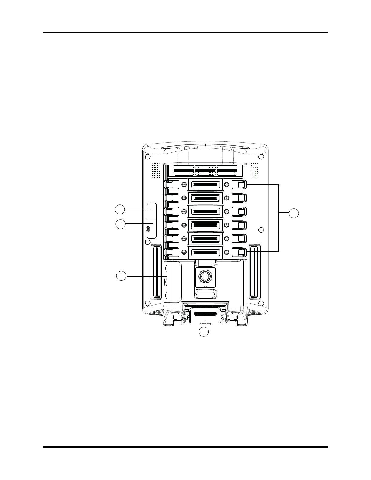
1.2.1 Connectors for Peripheral Devices
V 12 and V 21
V 12 and V 21 refer to the 12.1" monitor and 21.3" monitor respectively.
3
2
4
5
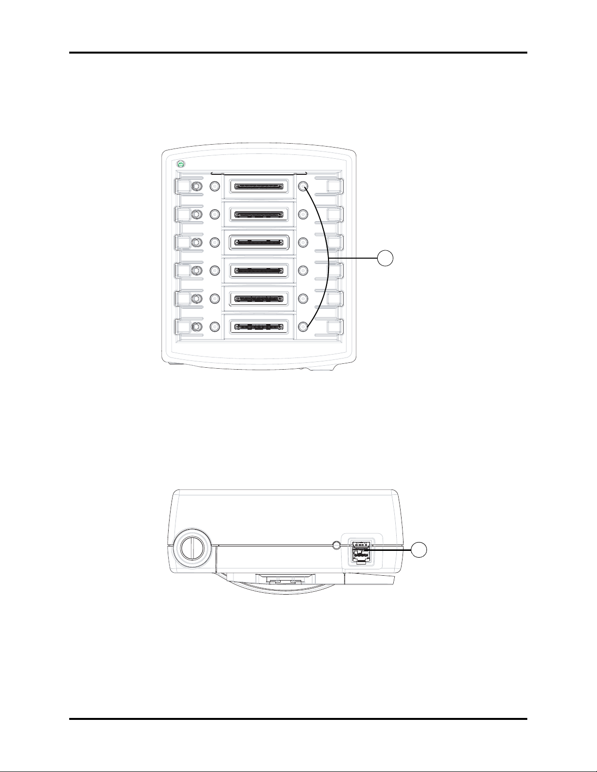
FIGURE 1-2 Example V 12 Rear View
1. Integrated module bays (for V 12 only) : Provides six module bays for modules and can
accommodate any combination of one, two or three bay wide modules that total six or less
bays.
2. V Hub connector: Connects V Hub via a PUSB cable.
3. RS-232 debug port: Connects a PC and is used for debug.
4. Battery connector (for V 12 only): Contains 3 battery connectors for removable batteries.
5. V Dock connector: Provides quick connection and release with components during
stationary operation.
1
1 - 2 046-001131-00 V Series Service Manual
Theory of Operation Connectors for Peripheral Devices and Indicators
33 6
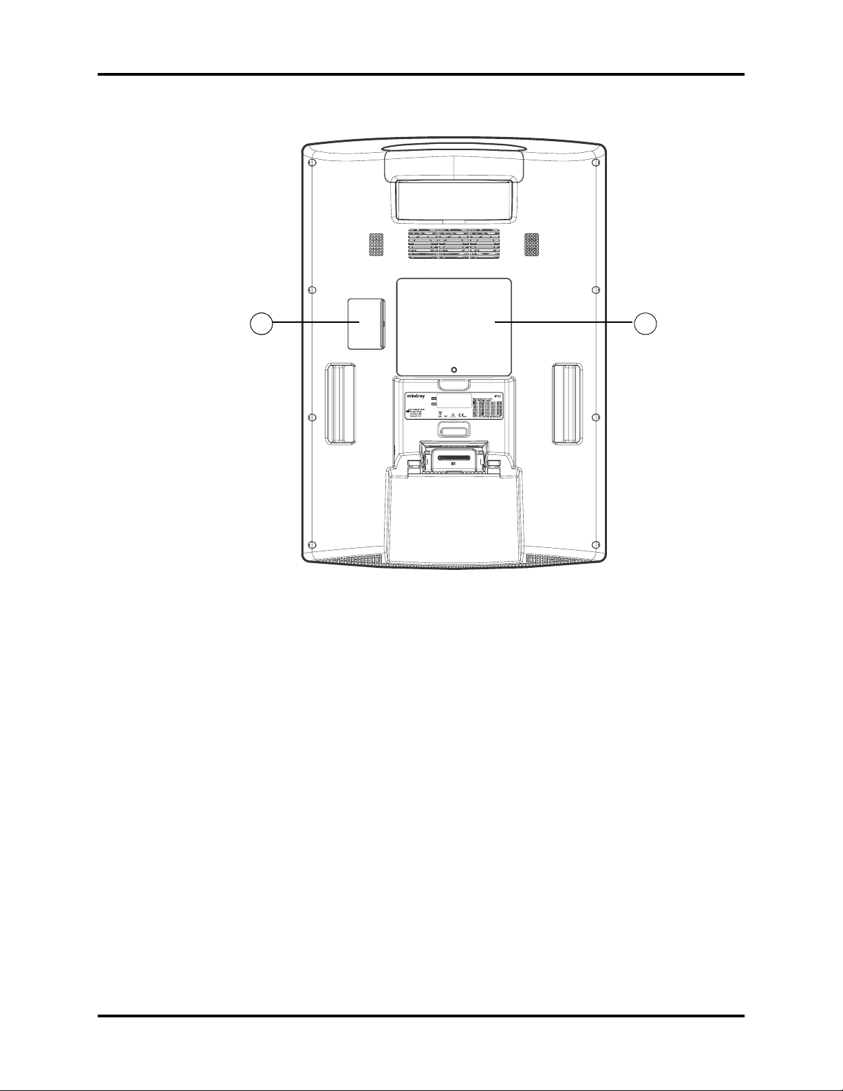
FIGURE 1-3 Example V 21 Rear View
3. RS-232 debug port: Connects a PC and is used for debug.
6. SATA connector (for V 21 only): Connects SATA driver (optional).
V Series Service Manual 046-001131-00 1 - 3

Connectors for Peripheral Devices and Indicators Theory of Operation
V Dock Physical Views
Front View
1
FIGURE 1-4 Example V Dock Front View
1. V Dock connector: Interfaces to a V 12 or V 21 monitor which allows for power and data
communication.
1 - 4 046-001131-00 V Series Service Manual
Theory of Operation Connectors for Peripheral Devices and Indicators
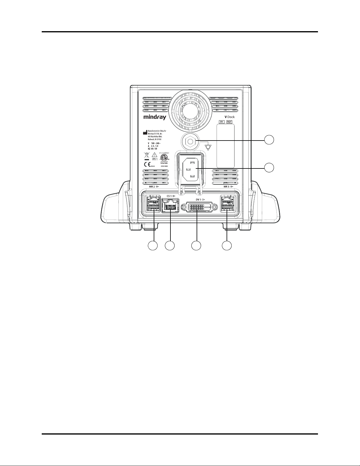
Rear View
1
2
3 4 35
FIGURE 1-5 Example V Dock Rear View
1. Equipotential lug: Connects the equipotential lug of other equipment when the monitor is
used with other equipment, eliminating the potential difference between them.
2. AC receptacle: Connects an AC power source (100-240 VAC, 50/60 Hz).
3. V Hub connector (3): Connects V Hub via PUSB cables.
4. Digital video interface (DVI) connector: Connects a second display via a DVI cable.
5. Central station (CS) connector: A RJ45 connector, through which a network or PC can be
connected.
V Series Service Manual 046-001131-00 1 - 5

Connectors for Peripheral Devices and Indicators Theory of Operation
Right Side View
2 1
FIGURE 1-6 Example V Dock Right Side View
1. V Hub connector (3): Connects V Hub via PUSB cables.
2. Standard USB connector or serial bus (3): Connects external USB devices.
Left Side View
2
1
FIGURE 1-7 Example V Dock Left Side View
1. Standard USB connector or serial bus (3): Connects external USB devices.
2. Nurse call: Connects nurse call relay.
1 - 6 046-001131-00 V Series Service Manual
Theory of Operation Connectors for Peripheral Devices and Indicators
V Hub Physical View
Front View
1
FIGURE 1-8 Example V Hub Front View
1. Integrated module bay (6): Accommodates any combination of one, two, or three bay wide
modules that totals six or less bays. It allows for power and data communication to modules.
Bottom View
1
FIGURE 1-9 Example V Hub Bottom View
1. V Hub connector: Allows for power and data communication to the monitor or V Dock.
V Series Service Manual 046-001131-00 1 - 7
Connectors for Peripheral Devices and Indicators Theory of Operation
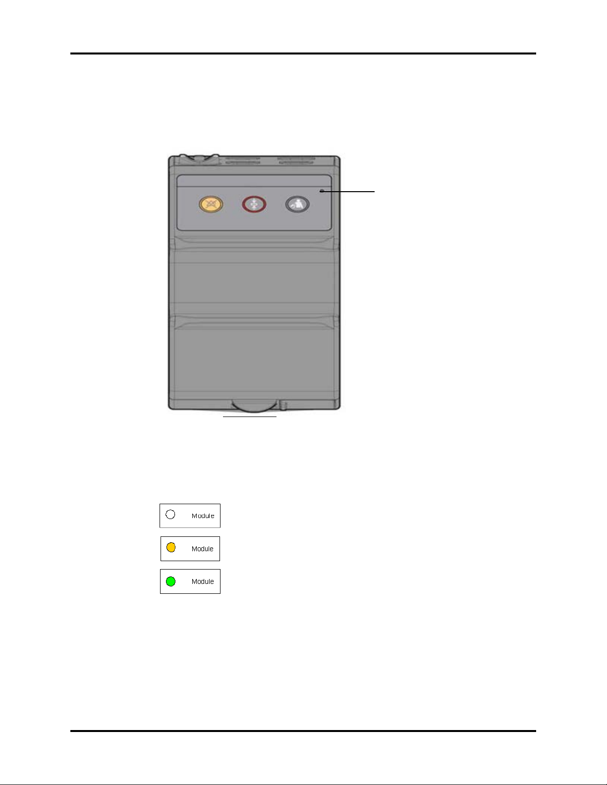
1.2.2 Indicators
Module Indicator
Each module has one indicator. The status indicator is a single bi-color LED (green/amber).
Indicator
FIGURE 1-10 Example VPS Front View
The status indicator shows three kinds of status levels.
Indicates unconnected and no power.
Indicates USB power and no communication. When a module is connected, the amber LED illuminates to indicate that USB power is available
to the module, but there is no communication.
Indicates fully functional and proper communication. Once the V Hub
communicates and is identified, the LED turns green.
1 - 8 046-001131-00 V Series Service Manual
Theory of Operation Connectors for Peripheral Devices and Indicators
V Hub Indicator
1
FIGURE 1-11 Example V Hub Indicator
1. Indicates the 12 Volt and 5 Volt power status of V Hub. When the V Hub indicator is off, it
indicates power source disconnection. When the V Hub indicator is lit in yellow, 5V is normal
but 12V is abnormal. When the V Hub indicator is lit in green, 12V is normal.
Battery Indicator
Battery indicators (for V 12 only) show the capacity and the charging status of each battery.
Alarm Indicator
Alarm Indicator
Battery Indicator
FIGURE 1-12 Example Battery Indicator
Alarm Indicator
Alarm indicators show the status of the patient monitor or patient. See FIGURE 1-12.
V Series Service Manual 046-001131-00 1 - 9
Main Unit Theory of Operation
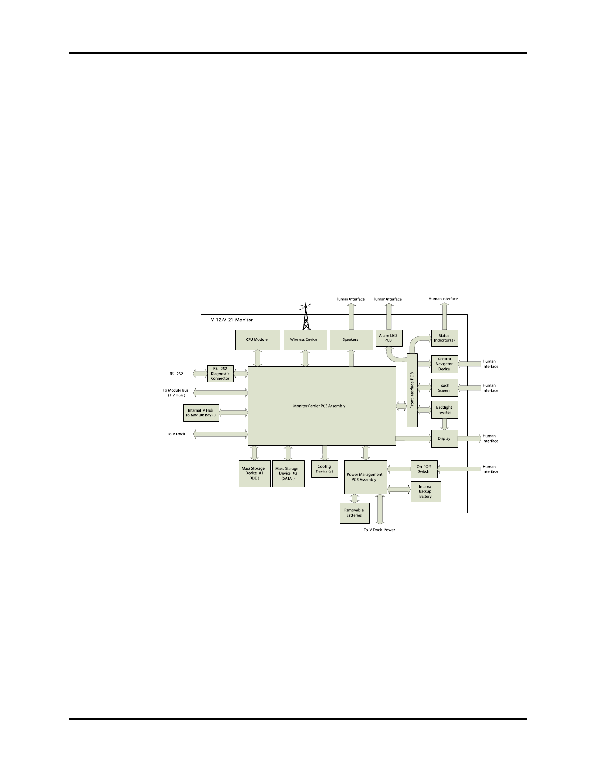
1.3 Main Unit
The patient monitor consists of :
• Input system: Touchscreen, touch pad, power button, keyboard/mouse
• Output system: LCD panel, alarm lamp, speaker, AC and battery status LEDs, recorder
• Processing and communications system: CPU module, monitor carrier board
• Power management system: Li-Ion battery, internal backup battery, battery interface board,
AC-DC power board, power management board (PMB)
• Power interface system: Monitor carrier board, V Dock
• Equipment interface system: Monitor carrier board, V Dock , V Hub
In addition, the patient monitor can also utilize a USB storage device, USB mouse, USB keyboard,
etc.
FIGURE 1-13 illustrates the architecture of V 12/V 21 patient monitor.
FIGURE 1-13 Electrical Architecture of V 12/V 21
1 - 10 046-001131-00 V Series Service Manual

Theory of Operation Main Unit
1.3.1 Input System
Touchscreen
The touchscreen is operable with or without gloves and provides a recalibration function.
Touc h Pad
The touch pad is only for the V 21 and located at the lower part of the monitor's front panel.
Power Button
The power button is located at the lower right part of V 12/V 21. Pressing it will power the
monitor on or off. The power button's status is detected by the power management board.
Keyboard / Mouse
USB keyboard and mouse is supported.
1.3.2 Output System
LCD Panel
The V 21 display uses a 21.3" LCD screen with a resolution of 1600x1200. V 12 display uses a 12.1"
LCD screen with a resolution of 768x1024. The LCD panel gets signals from the main board and
gets power from the inverter board, which is driven by the main board through the front
interface connector board.
Alarm Lamp
The monitor has two groups of alarm lamps on the alarm LED board, which is on the front panel.
The monitor I/O microprocessor passes the control signal to the LED driver TLC59116 via I2C bus.
Speaker
The speakers provide sound for alarms, heart beats, etc. They are driven by the COM Express
Module and the monitor I/O carrier board.
AC and Battery Status LEDs
The AC and battery status LEDs, located on V Dock (docking station), are controlled by the AC-DC
power board and PMB respectively. The PMB monitors battery status and passes the control
signal to V Dock via connectors.
Recorder
The Recorder module is used to print locally to a thermal recorder. The recorder gets power and
data from the V Hub through the non-Isolated module host communications board. The keypad/
LED is for indication and operation.
V Series Service Manual 046-001131-00 1 - 11

Main Unit Theory of Operation
1.3.3 Processing and Communications System
The processing and communication system mainly consists of two boards: CPU module and
monitor I/O carrier board.
CPU Module
The CPU module is a standard COM Express board, which is the heart of the patient monitor, and
implements a series of tasks including display processing, system control, data storage, and
processing, input and output system. The CPU module contains CPU, north-bridge, south-bridge,
DDR2 RAM, real-time clock, EEPROM, etc. It interfaces to the carrier board only, which then
provides interfaces to all other external devices.
Monitor Carrier Board
The monitor I/O carrier board is the CPU module's carrier board and will be described in detail in
section1.3.5 Equipment Interface System on Page 1-14 and Page 1-15.
1.3.4 Power Management System
Li-Ion Battery
• Three removable li-ion batteries are available. The battery compartment door is located at
the lower right of the patient monitor. The battery power is introduced to the power module
via the battery interface board and then processed and distributed to V 12 via the power
management board.
Internal Backup Battery
• The monitor uses one single-cell li-ion backup battery (P/N: 022-000006-00 SANYO
UR18650W high rate li-ion battery 3.7V 1500mAh). The battery is fixed to the battery
interface board.
Battery Interface Board
• The battery interface board serves as an interface between the batteries and the power
management board.
AC-DC Power Board
• The AC-DC power board converts input from AC power, and generates one regulated DC
output of voltage 15V. The output is turned on/off via connection or disconnection of the AC
power cord. The power supply provides an indication of AC presence.
• The Power Pin Board acts as a conduit for 12V and 15V to pass between the power supply and
mid and high acuity versions of the V Series patient monitor.
1 - 12 046-001131-00 V Series Service Manual

Theory of Operation Main Unit
Power Management Board (PMB)
This board is responsible for power management and performs the following functions:
• Auto-selects available power source (DS-DC, removable li-ion battery packs or internal li-ion
backup battery).
• Provides three regulated DC output voltages: 12V, 5V and 3.3V.
• Detects the power switch status to turn on/off the outputs.
• Monitors the system status (PS_ON) to hold the power or to turn it off.
• Provides over-voltage, over-current and short-circuit protection for all outputs.
• Monitors the input voltage and current provided to, and the output voltage and current draw
from each DC/DC converter output.
• Monitors the temperature of the PMB.
• Provides means to charge the three removable li-ion battery packs and the internal backup
battery and provides a CHRGR_ACTIVE output signal.
• Provides a UART interface to communicate with monitor I/O board and passes the PMB
information to monitor at a regular interval.
V Series Service Manual 046-001131-00 1 - 13
Main Unit Theory of Operation
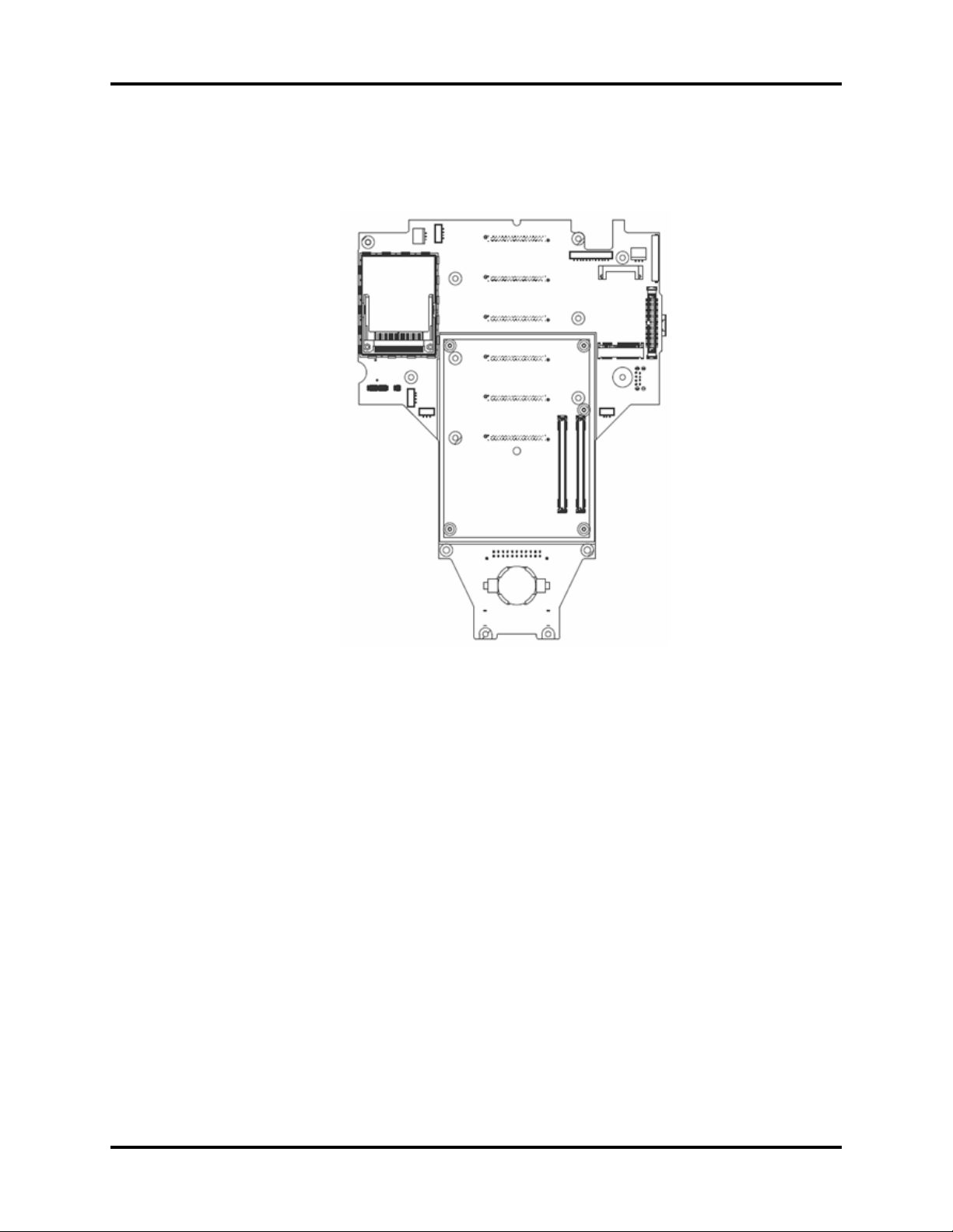
1.3.5 Equipment Interface System
Monitor Carrier Board
FIGURE 1-14 Monitor Carrier Board
The monitor carrier board implements the following tasks:
• Provides interfaces for CF, SATA, WiFi, LVDS display and so on.
• Communicates with PMB through UART and provides a debug serial port.
• Communicates with the CPU module through USB.
• Interfaces with I2C devices such as EEPROMs, the CPU module, alarm led drivers and Port
Expander.
• Monitors temperatures, detects fan status and controls fan speed.
• Detects dock presence and implements power control.
• Controls backlight and display brightness.
• Detects V Hub status and implements power control.
V Dock
V Dock (docking station) mounts to a fixed location and provides electrical connections for
network, power, USB, nurse call, display, and V Series module bus devices.
1 - 14 046-001131-00 V Series Service Manual
Theory of Operation Main Unit
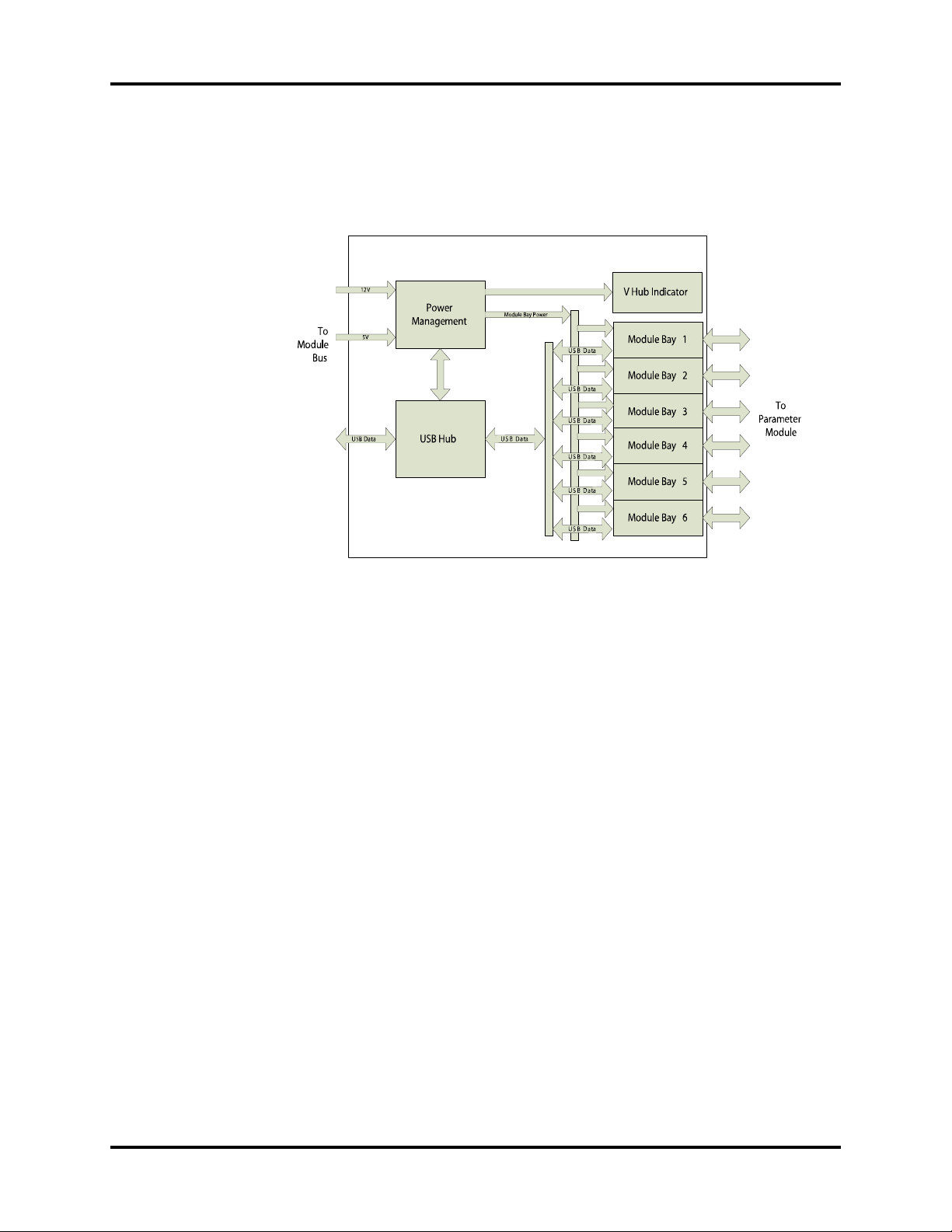
V Hub
V Hub provides the electrical interface between V 12/V 21 patient monitor and parameter
modules. It is used to extend the module bus to six module bays.
FIGURE 1-15 Electrical Architecture of V Hub
1.3.6 Interface Requirements
V Series Patient Monitor provides wired or wireless network interface to communicate with
Panorama, Hypervisor, etc. Wireless card is in V 12/V 21 and wired network connector is on the
docking station.
1.3.7 Parameter Module
Parameter modules include VPS, Recorder, VDI, CO2, C.O., IBP, TEMP,12L ECG/EKG, NIBP, SpO2.
Each parameter module consists of four parts: host communication board, keypad/LED,
parameter board and instrument/patient connector board.
The NI-HCB or HCB is the interface between module bus and the parameter board, playing a role
of power supply, data communication and processing. Parameter serves as the main source of
patient parameter data. Instruments or sensors are connected to parameter modules via the
instrument/patient connector board. Keypad/LED is for indication and operation.
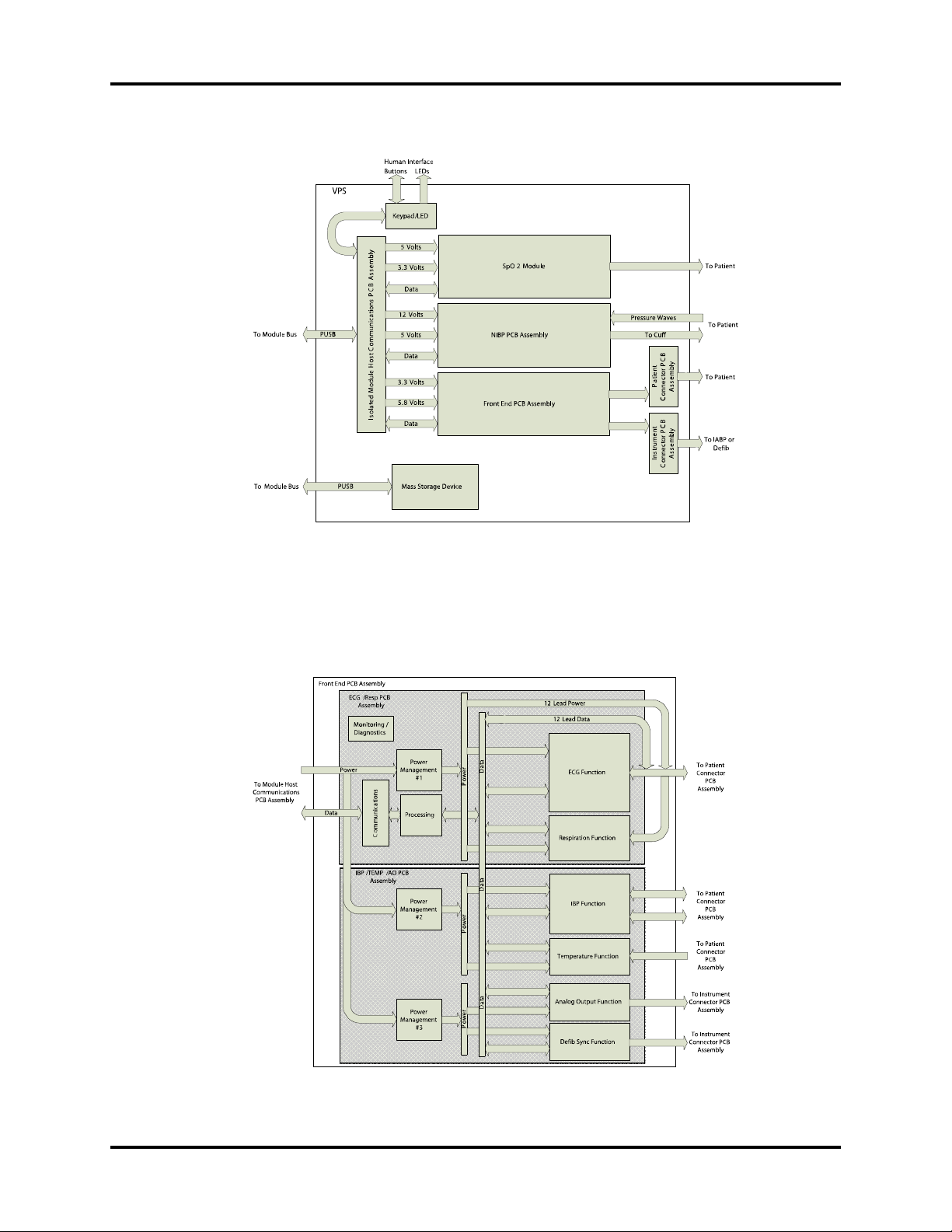
VPS (V Patient Server)
The VPS is a collection of the most commonly measured parameters, including 3/5/6 Lead ECG,
Respiration, Invasive Blood Pressure (2 channels), Temperature, SpO
Defibrillator Sync.
Otherwise the VPS also provides mass storage to store all patients' historical data and specific
configuration data. It is a 3X module.
, Analog Output (2), and a
2
FIGURE 1-16 shows the electrical architecture of VPS.
V Series Service Manual 046-001131-00 1 - 15
Main Unit Theory of Operation
FIGURE 1-16 Electrical Architecture of VPS
The Front End serves as the main source of patient parameter data. It contains the primary
functions of ECG, Respiration, IBP, and Temperature.
FIGURE 1-17 shows the electrical
architecture of front end module.
FIGURE 1-17 Electrical Architecture of Front End Module
1 - 16 046-001131-00 V Series Service Manual
Theory of Operation Main Unit
Recorder Module
The Recorder module prints to an internal thermal recorder. FIGURE 1-18 shows the electrical
architecture of recorder module.
Human Interface
Buttons
LEDs
To Module Bus
To Module Bus
Recorder Module
USB Data
V
2
1
o
s
t
l
V
5
o
s
t
l
Key Pad/LED
Non-Isolated Module Host
Communications PCB
Assembly
USB Data
Power
OEM Recorder
FIGURE 1-18 Electrical Architecture of Recorder Module
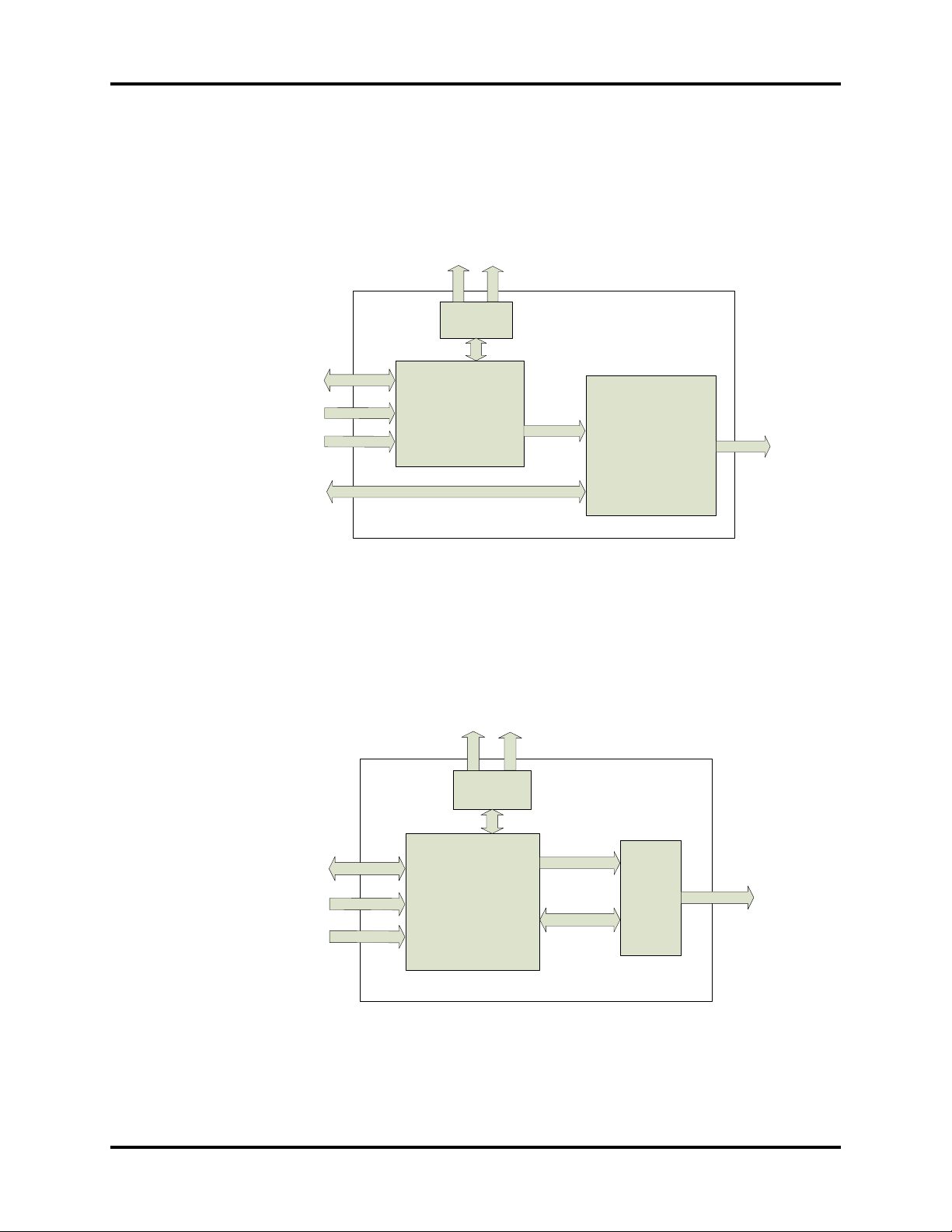
VDI Module
The VDI module acquires data from other medical devices supported by V series. It is a 1X
module.
FIGURE 1-19 shows the electrical architecture of VDI module.
Human Interface
Buttons
LEDs
Paper
Output
To Module Bus
VDI Module
USB Data
V
2
1
t
l
o
s
t
V
5
l
o
s
Key Pad/LED
Non-Isolated Module
Host Communications
PCB Assembly
Power
RS232 Data
Panel
Connector
PCB
assembly
Other
Devices
FIGURE 1-19 Electrical Architecture of VDI Module
V Series Service Manual 046-001131-00 1 - 17
Main Unit Theory of Operation
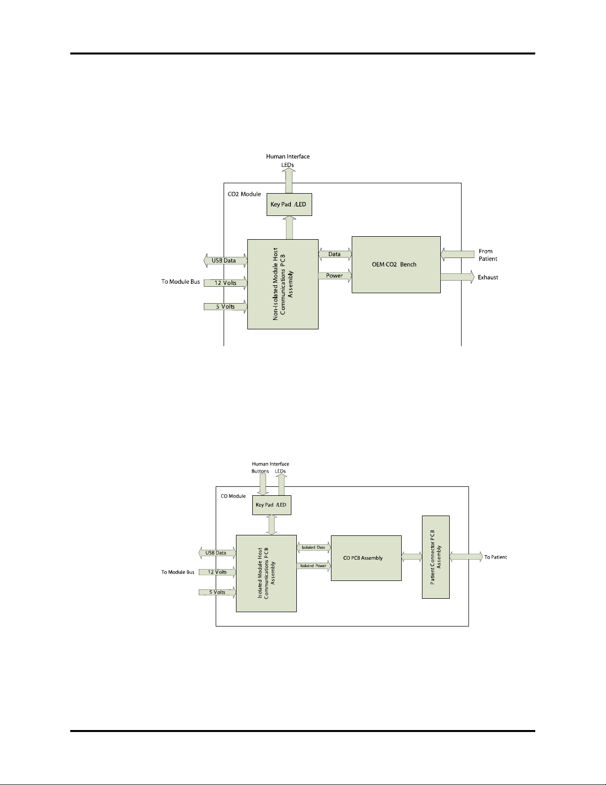
CO2 Module
The CO2 module measures the percentage of CO2 inspired and expired air from breathing. It is a
2X module.
FIGURE 1-20 shows the electrical architecture of CO2 module.
FIGURE 1-20 Electrical Architecture of CO2 Module
C.O. Module
The cardiac output module measures thermodilution cardiac output. It is a 1X module. FIGURE 1-
21 shows the electrical architecture of C.O. module.
FIGURE 1-21 Electrical Architecture of C.O. Module
1 - 18 046-001131-00 V Series Service Manual
Theory of Operation Main Unit
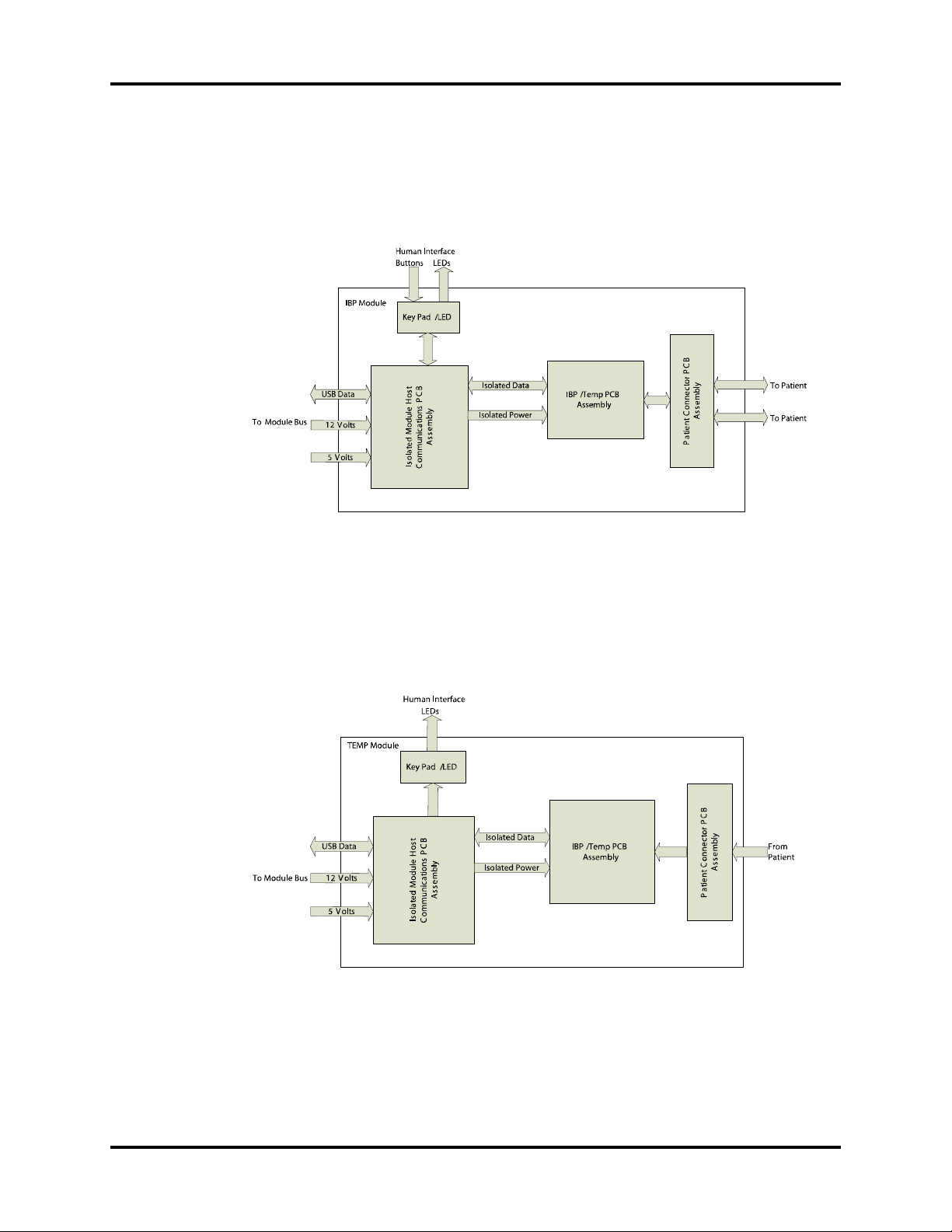
IBP Module
The IBP module measures the invasive blood pressure. It is a 1X module. FIGURE 1-22 shows the
electrical architecture of IBP module.
FIGURE 1-22 Electrical Architecture of IBP Module
TEMP Module
The Temp module measures temperature. It is a 1X module. FIGURE 1-23 shows the electrical
architecture of TEMP module.
FIGURE 1-23 Electrical Architecture of TEMP Module
V Series Service Manual 046-001131-00 1 - 19
Main Unit Theory of Operation
12L ECG/EKG Module
The12L ECG/EKG module monitors 12 lead ECG and Respiration including ST and arrhythmia
analysis through the VPS module.
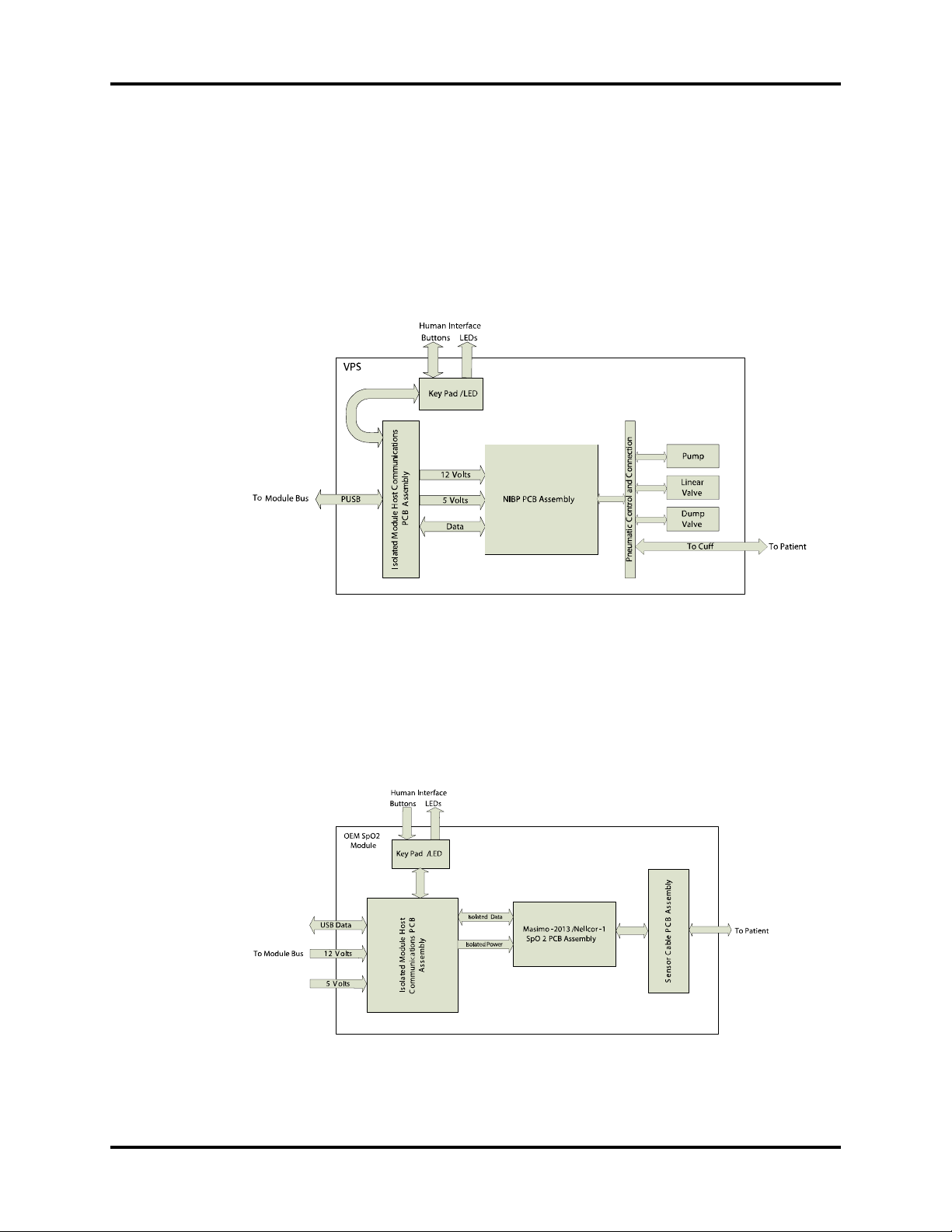
NIBP Module
The NIBP module measures non-invasive blood pressure. FIGURE 1-24 shows the electrical
architecture of NIBP module.
FIGURE 1-24 Electrical Architecture of NIBP Module
OEM SpO2 Module
There are two types of SpO2 modules: Masimo-2013 SpO2 and Nellcor-1 SpO2 module. Host
communication board, keypad/LED and patient connector board are also needed to work with
the OEM SpO
board. FIGURE 1-25 shows the electrical architecture of OEM SpO2 module.
2
FIGURE 1-25 Electrical Architecture of OEM SpO2 Module
1 - 20 046-001131-00 V Series Service Manual

2.0
Repair Information
2.1 Introduction
This chapter provides the necessary technical information to perform repairs on the instrument.
The most important prerequisites for effective troubleshooting are a thorough understanding of
the instrument functions as well as understanding the theory of operation.
2.2 Safety Precautions
In the event the instrument covers are removed, observe the following warnings and guidelines.
1. Do not short component leads together.
2. The instrument covers must not be removed by other than qualified technical personnel
who have received supplementary instructions regarding maintenance of medical
equipment or has equivalent experience in this area.
WARNING: Internal Electrical Shock Hazard -This unit does not contain any user-
serviceable parts. Do not remove instrument covers. Refer servicing to
qualified personnel.
WARNING: Whenever the monitor is opened for calibration or repair, a risk
(leakage) current safety check and a verification of basic functions of all
parameters should be performed before the monitor is returned
clinical use. See ‘‘Verification’’ on page 5-21 for details.
V Series Service Manual 046-001131-00 2 - 1

Troubleshooting Guidelines Repair Information
2.3 Troubleshooting Guidelines
1. Identify the problem
Due to the wide variety of potential symptoms certain problems may be more subtle than
others. One approach to troubleshooting is to set up the instrument as described in Chapter
5.0. Following the guidelines of the tests will help determine the problem if one exists.
2. Avoid shorting component leads
During repair procedures, it can become tempting to make a series of quick measurements.
Always turn the power off before connecting and disconnecting the test Leads and probes.
The accidental shorting of Leads can easily stress the components and cause a second fail
ure ( aside from the safety risk ).
3. Use the proper equipment
The equipment listed below is suggested to fulfill a wide range of troubleshooting requirements. It is imperative to use the designated equipment in order to ensure proper results of
any and all test procedures.
4. Clean up the repair area
After any repair, especially after any soldering or desoldering, clean off the repair area with
alcohol and a stiff brush. This will remove any residual solder flux, in turn allowing the instrument to return to its original appearance.
-
2.4 Special Tools Required
•DVM
• Digital mercury manometer - 0 to 300 mmHg
• Safety analyzer
• Patient simulator
• NIBP test chamber / Dummy cuff (P/N 0138-00-0001-01 (700 cc) or -03 (500 cc))
• CAT-5 crossover cable
• USB cable 2.0
• USB memory stick or USB hard drive 2.0 specified in the Operator's Manual
• Desktop PC or notebook PC
• Microsoft XP/Vista/Windows 7 operating system
• Intel Pentium CPU, above 500MHz
• Above 128M memory
• At least one net card
• At least one USB port
2 - 2 046-001131-00 V Series Service Manual

Repair Information Disassembly Instructions
2.5 Disassembly Instructions
This section describes the disassembly procedures for the patient monitor and its components.
Tools Required
• Screwdrivers
• Flat-bladed screwdrivers
• Sharp nose pliers
• 3-mm inner hexagon wrench
• ESD mat and wrist strap
• Antistatic glove
Preparation for Disassembly
1. Power down the V 12/V 21.
2. Remove the line cord from V Dock.
3. Remove all cable assemblies connecting to V 12/V 21, V Hub, and modules.
4. Remove all the modules from V 12/V 21 and V Hub.
5. Remove any batteries installed.
6. Perform all work on a properly grounded ESD workstation.
V Series Service Manual 046-001131-00 2 - 3

Disassembly Instructions Repair Information
2.5.1 Disassembling V 12 (12.1" Monitor)
Removal of the Diagnostics Access Cover
1. Open the module bus access and loosen the captive screw.
2. Remove the diagnostics access cover.
Diagnostics
Access Cover
Module Bus
Access
Captive Screw
2 - 4 046-001131-00 V Series Service Manual

Repair Information Disassembly Instructions
Removal of the Small Fan and Cable Assembly
1. Open the battery compartment door and use a flat-bladed screwdriver to push out the small
fan cover from the hole of the first battery door.
Small Fan Cover
2. Disconnect the small fan and cable assembly from the fan connecting cable.
NOTE: When reassembling the small fan, ensure that the fan is installed in the
proper direction.
2.5.2 Removal of the Battery Door
Open the battery door and remove it.
Small Fan
V Series Service Manual 046-001131-00 2 - 5

Disassembly Instructions Repair Information
2.5.3 Removal of the Front Housing
1. Place the monitor face down on a protective surface.
2. Use a small flat-bladed screwdriver to remove the 6-screw-hole covers.
2 - 6 046-001131-00 V Series Service Manual

Repair Information Disassembly Instructions
3. Remove the 6 M4X10 screws and loosen 2 captive screws from the rear of the monitor. Turn
the rear housing over to the top side of the front housing as indicated by the long arrow
shown in the first picture below.
Captive
Screws
Turn Ove r in
This Direction
Back
Housing
Assembly
Front
Housing
Assembly
V Series Service Manual 046-001131-00 2 - 7

Disassembly Instructions Repair Information
4. Remove the display cable from J13 of the carrier PCBA. Unlatch the sockets and remove the
front interface cable from J14 of the carrier PCBA and JP2 of the front Interface PCBA.
Removal of the Alarm LED PCBA / CCFL Inverter PCBA /Front Interface PCBA
1. Remove the alarm LED cable from J1. Remove the CCFL inverter cable from JP6.
2. Remove the touchscreen cable from J4. Remove the 2 MX6 screws that secure the front
interface PCBA.
Front In terface
PCBA
2 - 8 046-001131-00 V Series Service Manual

Repair Information Disassembly Instructions
3. Remove the alarm LED cable from J1. Remove the 2 M3X6 screws that secure the alarm LED
PCBA.
Alarm LED PCBA
4. Remove the LCD cable from CN2. Remove the CCFL inverter cable from CN1. Remove the 2
M3X6 screws that secure the CCFL inverter.
CCFL Inverter
PCBA
V Series Service Manual 046-001131-00 2 - 9

Disassembly Instructions Repair Information
Removal of the LCD/Display Cable /Touchscreen
1. Remove the 8 M3X6 screws. First pull the LCD subassembly out from the bracket. Then lift
the subassembly up and place the LCD face up.
2. Remove the display cable from the LCD. Remove the 4 M3X6 screws and separate the LCD
from the display mounting frame. Remove the touchscreen from the front housing.
Tou c h sc r ee n
LCD S ubassembly
2 - 10 046-001131-00 V Series Service Manual

Repair Information Disassembly Instructions
2.5.4 Removal of the Back Housing
Lie down the back housing and use an underlay to secure it.
Removal of the CF Solid State Drive
1. Open the CF Shield cover with sharp nose pliers clamping the tips of the cover.
CF Shield Cover
V Series Service Manual 046-001131-00 2 - 11

Disassembly Instructions Repair Information
2. Remove the CF solid state drive from the carrier PCBA by pushing it up forward.
CF Solid State Drive
Removal of the Wireless Transceiver/Antenna and Cable Assembly
1. Remove the 2 antenna and cables from the wireless transceiver.
2. Remove the 2 M3X6 screws that secure the fan mounting bracket. Then pull out the antenna
and cables.
Antenna and
Cable
Assembly
2 - 12 046-001131-00 V Series Service Manual

Repair Information Disassembly Instructions
3. Unfold the clips (two places) and remove the wireless transceiver.
Wireles s
Tra nsc ei ver
Removal of the Triple Fans and Cable Assembly
Remove the cable from the carrier PCBA J30. Remove the fans and gasket from the back housing.
Then remove the fans from the gasket.
Gasket
Trip le Fan
NOTE: When reassembling the fans, make the side of the fans with marks (the
figure on the left) face the symmetric holes of gaskets and the other
side (the figure on the right) face the dissymmetric holes. Ensure that
the side with marks face outside when assembling the fan to the back
housing.
Face outside Face inside
V Series Service Manual 046-001131-00 2 - 13

Disassembly Instructions Repair Information
Removal of the Speaker and Cable Assembly
Remove the speaker cable assembly from J9 and J12 of the carrier PCBA. Remove the 2 M3X6
screws and 2 speaker mounting brackets.
Speaker
Removal of the Handle
Remove the 2 M3X16 socket-head screws with 3-mm inner hexagon wrench. Separate the handle
from the back housing.
2 - 14 046-001131-00 V Series Service Manual

Repair Information Disassembly Instructions
Removal of the Carrier Board and CPU Subassembly
1. Remove the thermistor and cable assembly from J20 of the carrier board PCBA. Remove the
5 M3X6 pan head screws that secure the carrier PCBA. Remove the 6 M3X12 screws that
secure the heat-sink.
2. Hold the back of the heat-sink and pull the assembly out carefully.
Carrier Board and
CPU Subassembly
NOTE: EMI clip is assembled at the sixth rib on the heat-sink for V 12 only.
V Series Service Manual 046-001131-00 2 - 15

Disassembly Instructions Repair Information
Removal of the Fan Control PCBA
Remove the fan control PCBA from the back housing assembly. Remove the carrier board
connecting cable from J1. Remove the fan connecting cable from J2.
Fan Co ntrol PCBA
Removal of the Power Management PCBA
1. Remove the 4 M3X30 screws that secure the power management PCBA.
Power Management
PCBA
2. Separate the power management PCBA from the back housing assembly by pushing its
heat-sink to the right.
Push in This
Direction
2 - 16 046-001131-00 V Series Service Manual

Repair Information Disassembly Instructions
3. Slant the power management module toward 1 marked in the figure below and remove it.
4. Remove the pushbutton switch and cable from J3.
1
Removal of the Chassis Subassembly
1. Remove the 2 M4X10 screws and the thermistor and cable assembly.
Thermistor
and Cable
Assembly
2. Remove the captive screw in the bottom of the chassis and pull out the chassis assembly.
V Series Service Manual 046-001131-00 2 - 17

Disassembly Instructions Repair Information
3. Remove the 6 M3X6 screws to separate the li-ion battery pack PCBA.
Chassis Subassembly
Li-ion Battery Pack PCBA
Removal of the Pushbutton Switch and Cable Assembly
If the pushbutton switch and cable assembly in your unit is the one as shown below, loosen the
nut with sharp nose pliers
Pushbutton Switch and
Cable
and pull out the pushbutton switch and cable assembly carefully.
If the pushbutton switch and cable assembly in your unit is the one as shown below, loosen the
screw and remove the p
Pushbutton Switch and Cable
ushbutton switch and cable assembly.
Screw
2 - 18 046-001131-00 V Series Service Manual

Repair Information Disassembly Instructions
2.5.5 Disassembling V 21 (21.3" Monitor)
Removal of the Front Housing
1. Place the monitor face down on a protective surface.
2. Use a small flat-bladed screwdriver to remove the 8 screw hole covers.
Screw Hole Cover
3. Remove the 8 M4X10 screws from the rear of the monitor. Turn the rear housing over to the
left side of the front housing.
CAUTION: Do not tilt the rear housing for more than 45 degrees to prevent any
possible damage to the front interface cable inside the monitor.
Unlatch the sockets and remove the front interface cable from J14 of the carrier PCBA and JP2 of
the front interface PCBA.
V Series Service Manual 046-001131-00 2 - 19

Disassembly Instructions Repair Information
4. Remove the double-coated tape that secures the display cable. Remove the display cable
from J13 and J24 of the carrier PCBA. Remove the display cable from the socket of the LCD.
Double Coated Tape
Removal of the Front Interface PCBA / CCFL Inverter PCBA / Alarm LED PCBA / Front Plate/
To uc h pa d
1. Remove the alarm LED cable from J1.
2. Remove the touchpad cable from Jp10.
3. Remove the AC present cable from J3.
4. Remove the touchscreen cable from J4.
5. Remove the CCFL inverter cable from JP5.
6. Remove the 2 M3X6 screws that secure the front interface PCBA.
7. Remove the LCD cable from the CCFL inverter PCBA (6 places).
8. Remove the CCFL inverter cable from CN. Remove the 4 M3X6 screws that secure the CCFL
inverter PCBA.
2 - 20 046-001131-00 V Series Service Manual

Repair Information Disassembly Instructions
9. Remove the alarm LED cable from J1. Remove the 3 M3X6 screws that secure the alarm LED
PCBA.
10. Remove the 3 M3X6 screws that secure the front plate (shown in the picture above) and
turn the front plate around to separate the reclosable fastener.
Reclosable Fastener
Front Pl ate
NOTE: One EMI clip is assembled on the front plate.
11. Remove the 4 M3X6 screws that secure the touchpad mounting frame.
12. Remove the touchpad mounting frame.
V Series Service Manual 046-001131-00 2 - 21

Disassembly Instructions Repair Information
Tou c h pa d
Tou ch p ad
Mounting
Frame
Removal of the LCD/Touchscreen
1. Remove the 14 M3X6 screws that secure the LCD subassembly.
2. Lift the subassembly up and pull out the touchscreen cable carefully and place the LCD face
up. Separate the touchscreen from the front housing.
LCD S ubass embly
3. Remove the 2 M3X6 screws that secure the top bracket to the LCD.
4. Remove the 2 M3X6 screws that secure the bottom bracket to the LCD.
2 - 22 046-001131-00 V Series Service Manual

Repair Information Disassembly Instructions
Top Br ack et
Bottom Bracket
Removal of the Back Housing
Lie down the back housing and use an underlay to secure it.
V Series Service Manual 046-001131-00 2 - 23

Disassembly Instructions Repair Information
Removal of the CF Solid State Drive
1. Open the CF shield cover using sharp nose pliers to clamp the tips of the cover.
CF Shield Cover
2. Remove the CF solid state drive from the carrier PCBA by pushing it up forward.
CF Solid State Drive
2 - 24 046-001131-00 V Series Service Manual

Repair Information Disassembly Instructions
Removal of the Wireless Transceiver/Antenna and Cable Assembly
1. Remove the two antenna and cables from the wireless transceiver. Remove the 2 M3X6
screws that secure antenna mounting bracket. Then pull out the antenna and cables.
Antenna and
Cable
Assembly
NOTE: After reinstallation, the assembled antenna and cable assembly should
look the same as the one above.
2. Unfold the clips (2 places) and take out the wireless transceiver.
Wireles s
Tra nsc ei ver
V Series Service Manual 046-001131-00 2 - 25

Disassembly Instructions Repair Information
Removal of the Triple Fan and Cable Assembly
Remove the cable from the carrier PCBA J30. Remove the 2 screws that secure the fan mounting
bracket. Pull off the 12 fan mounting fasteners.
Triple Fan
Removal of the Speaker and Cable Assembly
Remove the speaker cable assembly from J9 and J12 of the carrier PCBA. Remove the 2 M3X6
screws and the 2 speaker mounting brackets.
Speaker
2 - 26 046-001131-00 V Series Service Manual

Repair Information Disassembly Instructions
Removal of the Small Fan/Handle
1. Remove the small fan cable from the socket of the fan control cable. Remove the M4x12
screws. Remove the 3 M2.5x12 screws.
Small Fan
2. Remove the other M4x12 screws and separate the handle from the back housing.
V Series Service Manual 046-001131-00 2 - 27

Disassembly Instructions Repair Information
Removal of the Carrier Board and CPU Subassembly
1. Remove the thermistor and cable assembly from J20 of the carrier board PCBA. If the carrier
board and CPU subassembly is the one as shown below, first remove the 2 M3X20 screws
that secure the
actuator bracket, then remove the 4 M3X16 screws that secure the heat-sink,
and then remove the 5 M3X6 screws that secure the carrier PCBA.
Heat-sink
Actuator Bracket
If the carrier board and CPU subassembly is the one as shown below, first remove the 6 M3X18
screws that secure the actuator bracket and the heat-sink and then remove the 5 M3X6 screws
that secure the carrier PCBA.
2 - 28 046-001131-00 V Series Service Manual

Repair Information Disassembly Instructions
2. Remove the 5 M3X6 screws that secure the carrier PCBA. Remove the 4 M3X12 screws that
secure the heat-sink.
3. Hold the back of the heat-sink and pull the subassembly out.
Carrier Board and
CPU Assembly
Removal of the Fan Control PCBA
Remove the fan control PCBA from the back housing assembly. Remove the carrier board
connecting cable from J1. Remove the fan connecting cable from J2.
Fan Co ntrol PCBA
V Series Service Manual 046-001131-00 2 - 29

Disassembly Instructions Repair Information
Removal of the Power Management PCBA
1. Remove the 4 M3X30 screws that secure the power management PCBA.
Power
Management
2. Separate the power management PCBA from the back housing assembly by pulling its heat-
sink to the right.
Push in This
Direction
3. Slant the power management module toward 1 marked in the figure below and remove it.
1
2 - 30 046-001131-00 V Series Service Manual

Repair Information Disassembly Instructions
4. Remove the pushbutton switch and cable from J3.
Removal of the Monitor Undocking Grips/ Chassis Subassembly
1. Remove the 8 M3X6 screws and 4 grip supports. Remove the undocking grips.
Grip Support
Undocking Grip
2. Remove the 2 M4X10 screws and the thermistor and cable assembly.
Thermistor and
Cable Assembly
V Series Service Manual 046-001131-00 2 - 31

Disassembly Instructions Repair Information
3. Remove the captive screw in the bottom of the chassis and pull out the chassis.
4. Remove the 6 M3X6 screws to separate the li-ion battery pack PCBA.
Chassis Subassembly
Li-ion Battery Pack PCBA
2 - 32 046-001131-00 V Series Service Manual

Repair Information Disassembly Instructions
Removal of the Pushbutton Switch and Cable Assembly
If the pushbutton switch and cable assembly in your unit is the one as shown below, loosen the
nut with sharp nose pliers
Pushbutton Switch and
Cable
and pull out the pushbutton switch and cable assembly carefully.
If the pushbutton switch and cable assembly in your unit is the one as shown below, loosen the
screw and remove the p
ushbutton switch and cable assembly.
Pushbutton Switch and Cable
Pushbutton Switch and Cable
Screw
Screw
V Series Service Manual 046-001131-00 2 - 33

Disassembly Instructions Repair Information
2.5.6 Disassembling V Dock
1. Place the V Dock (docking station) top-down and use an underlay to secure it.
2. Remove the 6 M4X10 screws.
3. Remove the bottom housing.
4. Remove the power cord retainer.
5. Open the rear cover.
Bottom Housing
Power Cord Retainer
Rear Cover
Removal of the Docking Station PCBA/Power Pin Board
1. Remove the AC/charge indicator cable from J14.
2. Remove the fan cable assembly from J16.
3. Remove the 4 M3X6 screws that secure the docking station PCBA.
Docking Station
PCBA
2 - 34 046-001131-00 V Series Service Manual

Repair Information Disassembly Instructions
4. Turn the docking station PCBA over to the other side.
5. Remove the 4 screws that secure the support bracket (as shown in the picture above). Then
separate the support bracket and the docking station PCBA.
NOTE: The support bracket includes a heat-sink and silica gel as shown below.
V Series Service Manual 046-001131-00 2 - 35

Disassembly Instructions Repair Information
6. Remove the power pin board.
7. Remove the cable of AC-DC power module from J1 of the power pin board.
Power Pin Board
2 - 36 046-001131-00 V Series Service Manual

Repair Information Disassembly Instructions
Removal of the AC-DC Power Module
1. Remove the 2 M3X6 screws.
2. Pull the AC-DC power module out of the top housing.
AC-DC Power Module
V Series Service Manual 046-001131-00 2 - 37

Disassembly Instructions Repair Information
2.5.7 Disassembling V Hub
Place the V Hub face down on a protective surface.
Removal of the Quick Release Subassembly
Remove the 4 M3X6 screws that secure the quick release subassembly.
Quick Release
Subassembly
Removal of the Back Housing
Remove the 5 M3X6 screws and open the back housing.
2 - 38 046-001131-00 V Series Service Manual

Repair Information Disassembly Instructions
Removal of the V Hub PCBA
1. Remove the lock assembly.
2. Remove the module locking bracket.
Lock Assembly
Module Locking Bracket
3. Remove the 12 M3X8 screws to remove the V Hub PCBA, if the V Hub PCBA is the one as
shown below.
Remove the 7 M3X8 pan head screws and 5 M3X8 plastic screws to remove the V Hub PCBA, if
the V Hub PCBA is the one as shown below.
V Series Service Manual 046-001131-00 2 - 39

Disassembly Instructions Repair Information
Removal of the Lock
1. Remove the bolt and the nut.
2. Remove the module locking cam and the lock assembly housing.
Removal of the Lock/Unlock indicate wheel
1. Remove the indicator retainer and the idler gear.
2. Remove the indicator.
Indicator
Retainer
Idler Gear
Indicator
2 - 40 046-001131-00 V Series Service Manual

Repair Information Disassembly Instructions
2.5.8 Disassembling VPS Module
Removal of the Front Housing
1. Remove the 4 M3X10 screws that secure the front housing.
2. Pull off the front housing from the back housing.
3. Remove the HCB module bay Interface FPC(HCB-FPC) from J1 of the isolator host
communication PCBA.
V Series Service Manual 046-001131-00 2 - 41

Disassembly Instructions Repair Information
Removal of the HCB Module Bay Interface FPC(HCB-FPC)/ the SSD Module Bay Interface
FPC(SSD-FPC)/USB PCBA
1. Remove the SSD-FPC from J1 of USB PCBA.
2. Remove the 3 M3X8 screws that secure the latch.
3. Remove the module latch and the module support mechanism.
4. Remove the back friction plate.
5. Remove the SSD-FPC and HCB-FPC.
HCB-FPC
Back Friction
Plate
SSD-FPC
Module Support
Mechanism
6. Remove the M3X8 screw that secures the USB PCBA.
USB PCBA
2 - 42 046-001131-00 V Series Service Manual

Repair Information Disassembly Instructions
Removal of the Patient Connector Interface Assembly
1. Remove the 2 M2.5X4 screws that secure the SpO2 connector.
2. Remove the tube from the NIBP fitting.
3. Unlatch the socket and remove ECG_RESP flex cable from J2 of the patient connector
interface PCBA.
4. Unlatch the socket and remove IBP_TEMP flex cable from J1 of the patient connector
interface PCBA.
Patient Connector
Interface Assembly
V Series Service Manual 046-001131-00 2 - 43

Disassembly Instructions Repair Information
Removal of the Instrument Connector Assembly
1. Pull out the instrument connector assembly.
2. Unlatch the connectors and remove instrument connector flex cable from J1.
Instrument
Connector
Assembly
Removal of the SpO2 PCBA/Isolator Host Communication PCBA / ECG_RESP_DSP PCBA/
IBP_TEMP_ AnalogOut PCBA
1. Remove the 2 M3X6 screws that secure the ECG/IBP/SpO2 assembly. Remove the HCB UART/
POWER cable from J2 of NIBP PCBA. Remove the small fan cable from the socket.
Small Fan
Cable
HCB UART
Power Ca ble
2. Pull out the ECG/IBP/SpO2 assembly from the back housing. Unlatch the socket and remove
keypad cable from J2 of the isolator host communication PCBA.
2 - 44 046-001131-00 V Series Service Manual

Repair Information Disassembly Instructions
ECG/IBP/SpO2 Assembly
3. Remove the 2 M3X4 screws and then remove the SpO2 PCBA.
4. Remove the SpO2 cable assembly.
5. Remove the 4 M3X6 screws that secure the isolator host communication PCBA.
6. Hold the PCBA and pull it off cautiously.
V Series Service Manual 046-001131-00 2 - 45

Disassembly Instructions Repair Information
Isolator Host Communication PCBA
7. Unlatch the socket and remove instrument connector flex cable from J2 of the IBP_TEMP_
AnalogOut PCBA.
8. Unlatch the socket and remove IBP_TEMP flex cable from J11 of the IBP_TEMP_ AnalogOut
PCBA.
9. Remove the 4 M3X6 screws that secure the IBP_TEMP_ AnalogOut PCBA.
10. Hold the PCBA and remove it cautiously.
IBP-TEMP Flex
Cable
Instrument
Connector Flex
Cable
Isolator Host
Communication
PCBA
11. Remove the 4 M3X6 screws that secure the ECG_RESP_DSP PCBA.
12. Pull out the PCBA and unlatch the ECG_RESP Flex cable from J11 of the ECG_RESP_DSP
PCBA.
2 - 46 046-001131-00 V Series Service Manual

Repair Information Disassembly Instructions
ECG-RESP Flex Cable
ECG-RESP-DSP PCBA
Removal of the NIBP Assembly
1. Remove the 2 M3X6 screws that secure the NIBP assembly. Pull the NIBP assembly out.
2. Remove the 2 M2.5X6 self-taping screws that secure the NIBP tubing retaining frame.
3. Remove the tubes from the fitting of the Linear Bleed Valve, the pump valve and the pump.
V Series Service Manual 046-001131-00 2 - 47

Disassembly Instructions Repair Information
Tub ing R eta inin g
Frame
Tub es
4. Remove the pump cable from J4 of the NIBP PCBA. Open the 2 mounting clamps that secure
the pump.
Mounting Clamp
Pump
5. Remove the 2 M2x4 screws that secure the dump valve.
6. Remove the dump valve cable from J7 of the NIBP PCBA.
Dump Valve
2 - 48 046-001131-00 V Series Service Manual

Repair Information Disassembly Instructions
7. Remove the 2 M3X16 screws and 2 M3 nuts.
8. Remove the linear bleed valve cable from J8 of the NIBP PCBA.
Linear Bleed Valve
9. Remove the 3 M3X6 screws that secure the NIBP PCBA.
10. Remove the 2 M2.5X16 screws that secure the small fan.
NIBP PCBA
V Series Service Manual 046-001131-00 2 - 49

Disassembly Instructions Repair Information
Removal of the Keypad
Tear off the overlay and the keypad with your fingers.
Removal of the Module Unlatching Trigger
Overlay
Keypad
1. Push the linkage to compress the spring and remove the M3X8 screw.
2. Remove the linkage and the trigger.
Linkage
Trigger
2 - 50 046-001131-00 V Series Service Manual

Repair Information Disassembly Instructions
2.5.9 Disassembling CO2 Module
Removal of the Front Housing
1. Remove the 4 M3X10 screws that secure the front housing.
2. Separate the front housing from the back housing.
3. Remove the HCB-FPC from J1 of the non-isolated host communications PCBA.
Removal of the HCB Module Bay Interface FPC (HCB-FPC)
1. Remove the 2 M3X8 screws that secure the latch.
2. Remove the module latch and the module support mechanism.
3. Remove the back friction plate.
4. Remove the HCB-FPC.
V Series Service Manual 046-001131-00 2 - 51

Disassembly Instructions Repair Information
HCB-FPC
ack Friction Plate
Module Support
Mechanism
Removal of the Patient Connector Assembly
1. Remove the tube from the CO2 pneumatic fitting.
2. Use a small blade screw driver to unclench the buckle that secure the CO2 input fitting.
Patient Connector
Assembly
2 - 52 046-001131-00 V Series Service Manual

Repair Information Disassembly Instructions
Removal of the CO2 Module Electronics Subassembly
1. Loosen the 2 M3X10 captive screws inside the bottom of the back housing.
2. Pull out the CO2 module electronics subassembly.
3. Unlatch the socket and remove the keypad cable from J2 of the non-Isolated host
communications PCBA.
CO2 Module
Electronics
Subassembly
Removal of the Non-Isolated Host Communications/CO2 Module
1. Remove the 4 M2.6X6 self tapping screws that secure the non-Isolated host
communications PCBA.
2. Remove the CO2 HCB UART/POWER cable from J4 of the CO2 module.
V Series Service Manual 046-001131-00 2 - 53

Disassembly Instructions Repair Information
Non-isolated Host
Communications PCBA
3. Remove the 4 M2.6X6 self tapping screws that secure the CO2 module
2.5.10 Disassembling 1X Module
Removal of the Front Housing
1. Remove the 2 M3X10 screws that secure the front housing.
CO2 Module
2. Pull off the front housing from the back housing. Remove the HCB-FPC from J1 of the host
communications PCBA.
2 - 54 046-001131-00 V Series Service Manual

Repair Information Disassembly Instructions
Removal of the HCB Module Bay Interface FPC (HCB-FPC)
1. Remove the 2 M3X8 screws that secure the latch.
2. Remove the module latch and the module support mechanism.
3. Remove the back friction plate.
4. Remove the HCB-FPC.
HCB-FPC
Back Friction
Plate
Module
Support
Mechanism
V Series Service Manual 046-001131-00 2 - 55

Disassembly Instructions Repair Information
Removal of the Patient Connector Assembly
Remove the cable from the socket of the patient connector PCBA.
Removal of the Module Electronics Subassembly
1. Remove the 1 screw that secures the module electronics subassembly.
2. Remove the module electronics subassembly from the back housing.
3. Unlatch the socket and remove the keypad cable from J2 of the host communications PCBA.
Module
Electronics
Subassembly
2 - 56 046-001131-00 V Series Service Manual

Repair Information Disassembly Instructions
4. Remove the 4 screws and 4 nuts that secure the host communications PCBA.
5. Separate the host communications PCBA and the parameter measurement PCBA.
Parame ter
Measurement
PCBA
Host
Communications
PCBA
Removal of the Non-Isolated Host Communications PCBA (Serial Port Module only)
Remove the 4 screws that secure the non-Isolated host communications PCBA.
Non-Isolated host
communications
PCBA
V Series Service Manual 046-001131-00 2 - 57

Disassembly Instructions Repair Information
2.5.11 Disassembling Recoder Module
Removal of the Front Housing
1. Remove the 4 screws that secure the front housing.
2. Pull off the front housing from the back housing.
3. Remove the HCB module bay interface FPC(HCB-FPC) from J1 of the isolator host
communication PCBA.
4. Remove the Recorder module bay interface FPC from J1 and J3 of the recorder.
2 - 58 046-001131-00 V Series Service Manual

Repair Information Disassembly Instructions
Removal of the HCB-FPC/ Recorder Module Bay Interface FPC
1. Remove the 3 M3X8 screws that secure the latch.
2. Remove the module latch and the module support mechanism.
3. Remove the back friction plate.
4. Remove the SSD-FPC and the Recorder module bay Interface FPC.
Recorder
module bay
interface FPC
SSD-FPC
Removal of the Recorder
1. Remove the recorder HCBUART/Power cable assembly from J2 of the recorder PCBA.
2. Open the recorder door and carefully remove the recorder assembly.
V Series Service Manual 046-001131-00 2 - 59

Disassembly Instructions Repair Information
Removal of the Non-Isolated Host Communications PCBA
1. Loosen the 2 M3X10 captive screws inside the bottom of the back housing.
2. Pull out the CO2 module electronics subassembly.
3. Remove the 4 M2.6X6 self tapping screws that secure the non-Isolated host
communications PCBA.
2 - 60 046-001131-00 V Series Service Manual

Repair Information Disassembly Instructions
2.5.12 Disassembling 12-Lead ECG Module
Removal of the Top Housing
1. Remove the top label and remove the 4 M3X16 screws that secure the top housing.
2. Separate the top housing and the bottom housing.
Removal of the 12-Lead Resp Board and the 12-Lead ECG Board
1. Separate the 12 -Lead Resp board and the 12-Lead ECG board
12-Lead Resp Board
V Series Service Manual 046-001131-00 2 - 61

Disassembly Instructions Repair Information
2. Remove the 12-Lead ECG board from the bottom housing.
12-Lead ECG
Board
Removal of the Patient Cable of the 12L ECG Module / the Monitor Cable of the 12L ECG
Module
1. Remove the patient cable from J1 of the 12L ECG board.
2. Remove the monitor cable from J4 of the 12L Resp board.
Patient Cable
Monitor Cable
2 - 62 046-001131-00 V Series Service Manual

Repair Information Cable Wiring Diagrams
2.6 Cable Wiring Diagrams
2.6.1 Nurse Call Cable (3 Pin Circular to Unterminated)
P/N 0012-00-1277-01/-02
6 ft+/- 1in
3
1
2
in
1
+/- .
in.
13
9 ft +/- 6 in.
3
2
1
Connector
shield
Cable shield
RED
WHT
BLK
E1
E2
E3
E4
E8
E5
E6
E7
Circuit Board
FIGURE 2-1 Nurse Call Cable (3 Pin Circular to Unterminated )
Cable
shield
BLK
NC
RED
NO
WHT
Common
V Series Service Manual 046-001131-00 2 - 63

Cable Wiring Diagrams Repair Information
2.6.2 Defib Synch Cable
P/N 0012-00-1801-01
STRIPPED AND TINNED 0.5in.
1
6
+_
9
5
_
+
4
GND
GND
GND
GND
GND
IBP OUT 1
IBP OUT 2
ECG OUT
ETRIG OA
1
1
2
3
4
5
6
7
8
9
15 ft
_
+
2 in.
P1
Connector shell
2.5
0.5
STRIP JACKET
FIGURE 2-2 Defib Synch Cable
2.6.3 Serial Port to Serial Port Cable
P/N 0012-00-1275-01
FIGURE 2-3 Serial Port to Serial Port Cable
2 - 64 046-001131-00 V Series Service Manual

Repair Information Cable Wiring Diagrams
2.6.4 ECG Shielded Lead Wires
2.6.4.1 3/5 Lead ECG Leadset
Leadset, ECG, 3/5 Lead, Snap
POSITION 6
LEADWIRE
TERMINALS
RL/N
LA/L
LL/F
RA/R
V/C
SHIELD
POSITION 1
LEADWIRE
PLUG POSITIONS
5
4
3
2
1
10
9
8
7
6
PART NUMBER DESCRIPTION
0012-00-1503-01 Leadset, ECG, 5 Lead, Snap, AAMI, 18”
0012-00-1503-02 Leadset, ECG, 5 Lead, Snap, AAMI, 24”
0012-00-1503-03 Leadset, ECG, 5 Lead, Snap, AAMI, 36”
0012-00-1503-10 Leadset, ECG, 5 Lead, Snap, IEC, 18”
0012-00-1503-11 Leadset, ECG, 5 Lead, Snap, IEC, 24”
0012-00-1503-12 Leadset, ECG, 5 Lead, Snap, IEC, 36”
V Series Service Manual 046-001131-00 2 - 65

Cable Wiring Diagrams Repair Information
POSITION 1
POSITION 6
LEADWIRE
PLUG POSITIONS
5
LEADWIRE
TERMINALS
LA/L
10
4
9
LL/F
RA/R
SHIELD
3
8
2
7
6
1
PART NUMBER DESCRIPTION
0012-00-1503-04 Leadset, ECG, 3 Lead, Snap, AAMI, 18”
0012-00-1503-05 Leadset, ECG, 3 Lead, Snap, AAMI, 24”
0012-00-1503-06 Leadset, ECG, 3 Lead, Snap, AAMI, 36”
0012-00-1503-13 Leadset, ECG, 3 Lead, Snap, IEC, 18”
0012-00-1503-14 Leadset, ECG, 3 Lead, Snap, IEC, 24”
0012-00-1503-15 Leadset, ECG, 3 Lead, Snap, IEC, 36”
2 - 66 046-001131-00 V Series Service Manual

Repair Information Cable Wiring Diagrams
Leadset, ECG, 3/5 Lead, Pinch
LEADWIRE
TERMINALS
RL/N
LA/L
LL/F
RA/R
V/C
SHIELD
POSITION 1
LEADWIRE
PLUG POSITIONS
5
4
3
2
1
10
9
8
7
6
POSITION 2
10
PART NUMBER DESCRIPTION
0012-00-1514-01 Leadset, ECG, 5 Lead, Pinch, AAMI, 18”
0012-00-1514-02 Leadset, ECG, 5 Lead, Pinch, AAMI, 24”
0012-00-1514-03 Leadset, ECG, 5 Lead, Pinch, AAMI, 36”
0012-00-1514-10 Leadset, ECG, 5 Lead, Pinch, IEC, 18”
0012-00-1514-11 Leadset, ECG, 5 Lead, Pinch, IEC, 24”
0012-00-1514-12 Leadset, ECG, 5 Lead, Pinch, IEC, 36”
V Series Service Manual 046-001131-00 2 - 67

Cable Wiring Diagrams Repair Information
POSITION 1
POSITION 6
LEADWIRE
PLUG POSITIONS
LEADWIRE
TERMINALS
LA/L
5
4 9
10
LL/F
RA/R
SHIELD
3
8
2
7
1
6
PART NUMBER DESCRIPTION
0012-00-1514-04 Leadset, ECG, 3 Lead, Pinch, AAMI, 18”
0012-00-1514-05 Leadset, ECG, 3 Lead, Pinch, AAMI, 24”
0012-00-1514-06 Leadset, ECG, 3 Lead, Pinch, AAMI, 36”
0012-00-1514-13 Leadset, ECG, 3 Lead, Pinch, IEC, 18”
0012-00-1514-14 Leadset, ECG, 3 Lead, Pinch, IEC, 24”
0012-00-1514-15 Leadset, ECG, 3 Lead, Pinch, IEC, 36”
2 - 68 046-001131-00 V Series Service Manual

Repair Information Cable Wiring Diagrams
2.6.4.2 6-Lead ECG Leadset
Leadset, ECG, 6 Lead, Snap
POSITION 2
SIGNAL
DESCRIPTION
RL/N
LA/L
LA/F
RA/R
Vx/Cx
Vy/Cy
LEADWIRE
TERMINALS
SHIELD
POSITION 1
LEADWIRE
PLUG POSITIONS
6 12
5
4
4
3 9
2
1
11
10
8
7
PART NUMBER DESCRIPTION
0012-00-1773-01 Leadset, ECG, 6 Lead, Snap, AAMI, 18”
0012-00-1773-02 Leadset, ECG, 6 Lead, Snap, AAMI, 24”
0012-00-1773-03 Leadset, ECG, 6 Lead, Snap, AAMI, 36”
0012-00-1773-11 Leadset, ECG, 6 Lead, Snap, IEC, 18”
0012-00-1773-12 Leadset, ECG, 6 Lead, Snap, IEC, 24”
0012-00-1773-13 Leadset, ECG, 6 Lead, Snap, IEC, 36”
V Series Service Manual 046-001131-00 2 - 69

Cable Wiring Diagrams Repair Information
Leadset, ECG, 6 Lead, Pinch
SIGNAL
DESCRIPTION
RL/N
LA/L
LL/F
RA/R
Vx/Cx
Vy/Cy
LEADWIRE
TERMINALS
SHIELD
POSITION 1
LEADWIRE
PLUG POSITIONS
6
5
4
3
2
1
POSITION 2
12
11
10
9
8
7
PART NUMBER DESCRIPTION
0012-00-1816-01 Leadset, ECG, 6 Lead, Pinch, AAMI, 18”
0012-00-1816-02 Leadset, ECG, 6 Lead, Pinch, AAMI, 24”
0012-00-1816-03 Leadset, ECG, 6 Lead, Pinch, AAMI, 36”
0012-00-1816-11 Leadset, ECG, 6 Lead, Pinch, IEC, 18”
0012-00-1816-12 Leadset, ECG, 6 Lead, Pinch, IEC, 24”
0012-00-1816-13 Leadset, ECG, 6 Lead, Pinch, IEC, 36”
2 - 70 046-001131-00 V Series Service Manual

Repair Information Cable Wiring Diagrams
2.6.4.3 Extension Lead ECG Leadset
Leadset, ECG, Extension, Snap
LEADWIRE
TERMINALS
V2/C2
V3/C3
V4/C4
V5/C5
V6/C6
SHIELD
POSITION 1
LEADWIRE
PLUG POSITIONS
5
4
3
2
1
POSITION 6
10
9
8
7
6
PART NUMBER DESCRIPTION
0012-00-1818-01 Leadset, ECG, Extension, Snap, AAMI, 18”
0012-00-1818-02 Leadset, ECG, Extension, Snap, AAMI, 24”
0012-00-1818-03 Leadset, ECG, Extension, Snap, AAMI, 36”
0012-00-1818-10 Leadset, ECG, Extension, Snap, IEC, 18”
0012-00-1818-11 Leadset, ECG, Extension, Snap, IEC, 24”
0012-00-1818-12 Leadset, ECG, Extension, Snap, IEC, 36”
V Series Service Manual 046-001131-00 2 - 71

Cable Wiring Diagrams Repair Information
Leadset, ECG, Extension, Pinch
V2/C2
V3/C3
V4/C4
V5/C5
V6/C6
SHIELD
LEADWIRE
TERMINALS
POSITION 1
LEADWIRE
PLUG POSITIONS
5
4
3
2
1
POSITION 6
10
9
8
7
6
PART NUMBER DESCRIPTION
0012-00-1820-01 Leadset, ECG, Extension, Pinch, AAMI, 18”
0012-00-1820-02 Leadset, ECG, Extension, Pinch, AAMI, 24”
0012-00-1820-03 Leadset, ECG, Extension, Pinch, AAMI, 36”
0012-00-1820-10 Leadset, ECG, Extension, Pinch, IEC, 18”
0012-00-1820-11 Leadset, ECG, Extension, Pinch, IEC, 24”
0012-00-1820-12 Leadset, ECG, Extension, Pinch, IEC, 36”
2 - 72 046-001131-00 V Series Service Manual
 Loading...