


Disassembling Guide for
Ex-55/65
International Customer Service Department
Mindray CO. Ltd.
2008.09 (Ver 1.1)
- 1 -

Content
Warning........................................................................................................................- 3 -
Note..............................................................................................................................- 3 -
1 Tools..........................................................................................................................- 4 -
2 Preparations for Disassembly.................................................................................- 4 -
3 Circuit System Disassembly...................................................................................- 6 -
3.1 Remove the Top Panel............................................................................................- 6 -
3.2 Remove the CPU board..........................................................................................- 7 -
3.3 Remove the Button Board ...................................................................................... - 8 -
3.4 Remove the Monitor Board....................................................................................- 8 -
3.5 Remove the Net Board...........................................................................................- 9 -
3.6 Remove the CIS interface board............................................................................- 9 -
3.7 Remove the Built-in Batteries..............................................................................- 10 -
3.8 Remove the Speaker............................................................................................. - 11 -
3.9 Remove the Three-way Valve .............................................................................. - 11 -
3.10 Remove the Power Board...................................................................................- 12 -
4 Pneumatic System Disassembly ..........................................................................- 14 -
4.1 Remove the Upper Rear Panel............................................................................. - 14 -
4.2 Remove the Front Panel.......................................................................................- 15 -
4.3 Remove the Display Assembly ............................................................................- 15 -
4.4 Remove the High Voltage Inverter.......................................................................- 17 -
4.5 Remove the System Switch..................................................................................- 17 -
4.6 Remove the Flow Meter control board. ............................................................... - 18 -
4.7 Remove the Alarm Light......................................................................................- 19 -
4.8 Remove the Encoder Board ................................................................................. - 20 -
4.9 Remove the O2 Flush Button...............................................................................- 20 -
4.10 Remove the Pipeline or Cylinder Pressure Gauges............................................- 21 -
4.11 Remove the Flow Meter.....................................................................................- 22 -
4.12 Remove the Needle Valves.................................................................................- 22 -
4.13 Remove the Module Socket Communication Board (NIOS).............................- 23 -
4.14 Remove the Pipeline Gas Supply Inlet Assembly..............................................- 23 -
4.15 Disassemble the Pipeline Gas Supply Inlet Assembly....................................... - 24 -
4.16 Remove the ACGO Switch ................................................................................- 25 -
4.17 Remove the Breathing Valve Assembly............................................................. - 25 -
4.18 Remove the O2-N2O block valve......................................................................- 26 -
5 Electrical and Pneumatic Diagrams .....................................................................- 27 -
5.1 Electrical Connections .........................................................................................- 27 -
5.2 Pneumatic Connections........................................................................................ - 28 -
5.3 Modular Connections...........................................................................................- 29 -
- 2 -

Warning
To help prevent fires, only use lubricants approved for anesthesia or O2 equipment.
Do not use lubricants that contain oil or grease. They burn or explode in high O2
concentrations.
Obey infection control and safety procedures. Used equipment may contain blood and
body fluids.
Movable parts and removable components may present a pinch or a crush hazard. Use
care when moving or replacing system parts and components.
Use care when disassembling the parts with sharp edges to avoid cuts.
Pay attention to the screws during the disassembly to prevent screws from falling into the
inside of the equipment. Failure to do so may cause short circuit.
Make sure to bleed gas pressure before disassembling pneumatic fittings to avoid
personal injury caused by high pressure gas.
Note
When re-assembling, inspect all parts for deterioration. Replace them if necessary. Use
appropriate screws and parts.
After repairs are completed or parts replaced, you are required to perform the checkout
procedure. Please refer to Service Manual PART 4 “Checkout and Test”.
- 3 -

1 Tools
During disassembling and replacing, the following tools may be required:
Inner hexagon wrench
Electric screwdriver
Diagonal pliers
Flathead screwdriver
Drawer spacing fixer
M4 sleeve screwdriver
Flow meter positioning fixture
Adjustable wrench
Tweezers
2 Preparations for Disassembly
Before disassembly,
1. Make sure:
The anesthesia machine is stopped.
Bleed the gas pressure from the anesthesia machine as described below.
Disconnect the AC power supply.
Disconnect all pipeline and cylinder gas supplies.
Prepare the tools required for disassembly.
Maneuver the anesthesia machine to an appropriate location and then step the four caster
brakes to fix the machine.
- 4 -

2. Bleeding Gas Pressure
Make sure to bleed the gas pressure from the anesthesia machine before disassembling
pneumatic fittings to avoid personal injury or equipment damage. Bleed gas pressure as
follows:
1. Set the system switch to ON.
2. Close other cylinder valves and disconnect pipeline gas supplies. Do not disconnect the
O2 pipeline. If pipeline O2 is not available, connect O2 cylinder and open the O2 cylinder
valve.
3. Turn the flow controls for all gases (except O2) to the minimum flow.
4. Ensure that all cylinder and pipeline pressure gauges read zero.
5. Disconnect the O2 pipeline supply (or close the O2 cylinder valve). Press the O2 flush
button to bleed O2 from the system.
6. Set the system switch to OFF.
- 5 -

3 Circuit System Disassembly
3.1 Remove the Top Panel
1 Pry up the eight screws covers and unscrew the eight screws exposed.
2 Lift the top panel followed by disconnecting the cable marked in the picture.
- 6 -

3. Then you can see the circuit part.
3.2 Remove the CPU board
★Please first finish Part 3.1, then:
Disconnect all the cables and remove the four screws and then take out the CPU board.
- 7 -

3.3 Remove the Button Board
★Please first finish Part 3.1, then:
Disconnect all the cables and remove the four screws and then take out the button board.
3.4 Remove the Monitor Board
★Please first finish Part 3.1, then:
Disconnect all the cables and tubes from the monitor board. Then unscrew the four
screws marked in the picture to remove the monitor board.
- 8 -

3.5 Remove the Net Board
★Please first finish Part 3.1, then:
Disconnect the cable from the CPU board to the net board and remove the two screws
then take out the net board.
3.6 Remove the CIS interface board
★Please first finish Part 3.1, then:
Disconnect the cable from the CPU board to the net board and remove the three screws
then take out the CIS interface board.
- 9 -

3.7 Remove the Built-in Batteries
★Please first finish Part 3.1, then:
Unscrew the six screws (marked in the picture) and the two nuts on the battery assembly.
Disconnect the cable to take out the battery box.
- 10 -
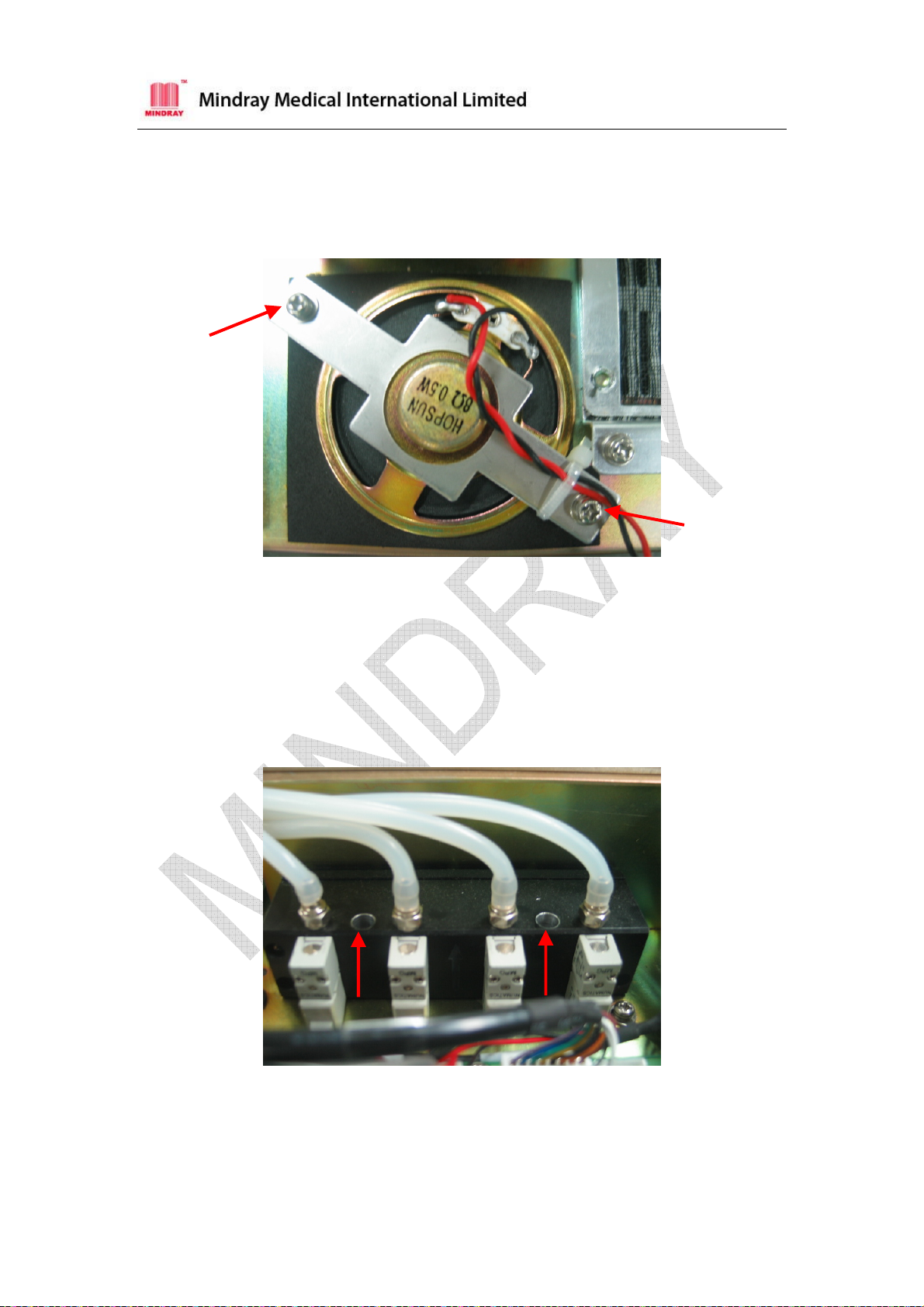
3.8 Remove the Speaker
★Please first finish Part 3.1, then:
Disconnect the cables from the speaker. Unscrew the two screws to remove the speaker.
3.9 Remove the Three-way Valve
★Please first finish Part 3.1, then:
Disconnect the cables and tubes from the three-way valve. Then unscrew the two screws
marked in the picture to remove the three-way valve.
- 11 -
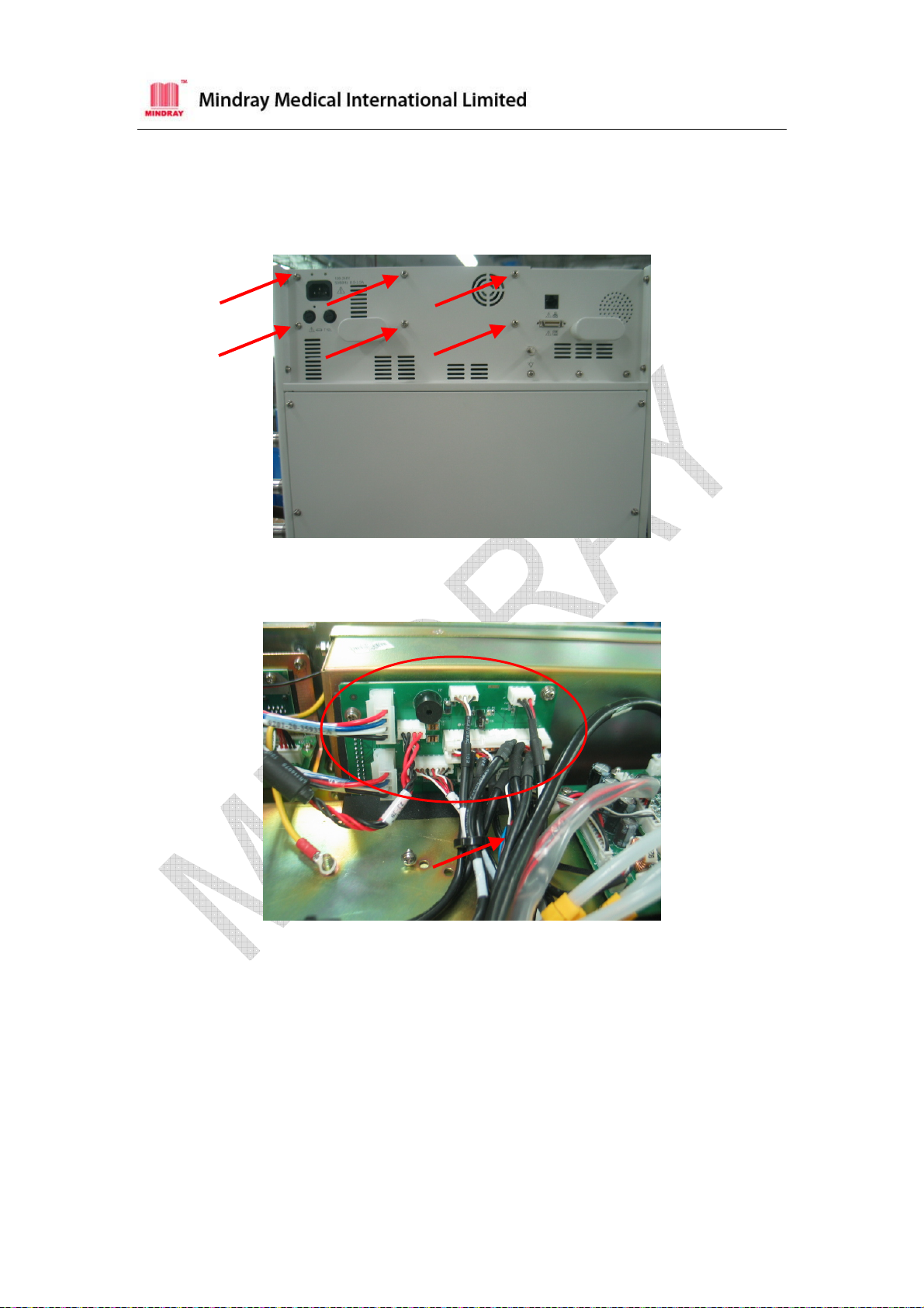
3.10 Remove the Power Board
★Please first finish Part 3.1, then:
1 Unscrew the six screws as shown below.
2 Take out the power box after disconnecting the cables from the power conversion
board marked in the picture.
- 12 -

3 Disconnect the five screws on the power conversion board marked in the picture.
4 Unscrew the four screws on both sides of the power box to open the power box.
5 Unscrew the four screws marked in the picture to remove the power board.
- 13 -

4 Pneumatic System Disassembly
4.1 Remove the Upper Rear Panel
1 Unscrew the six screws to remove the upper rear panel as shown below.
2 Then you can see the Pneumatic System as below.
- 14 -
4.2 Remove the Front Panel
★Please first finish Part 3.1, Part 4.1, then:
Unscrew the two screws and then disconnect the pipes connecting from the front panel to
system switch, O2 flush button, flow meter, needle valves, pressure gauges, and carefully
take the panel out.
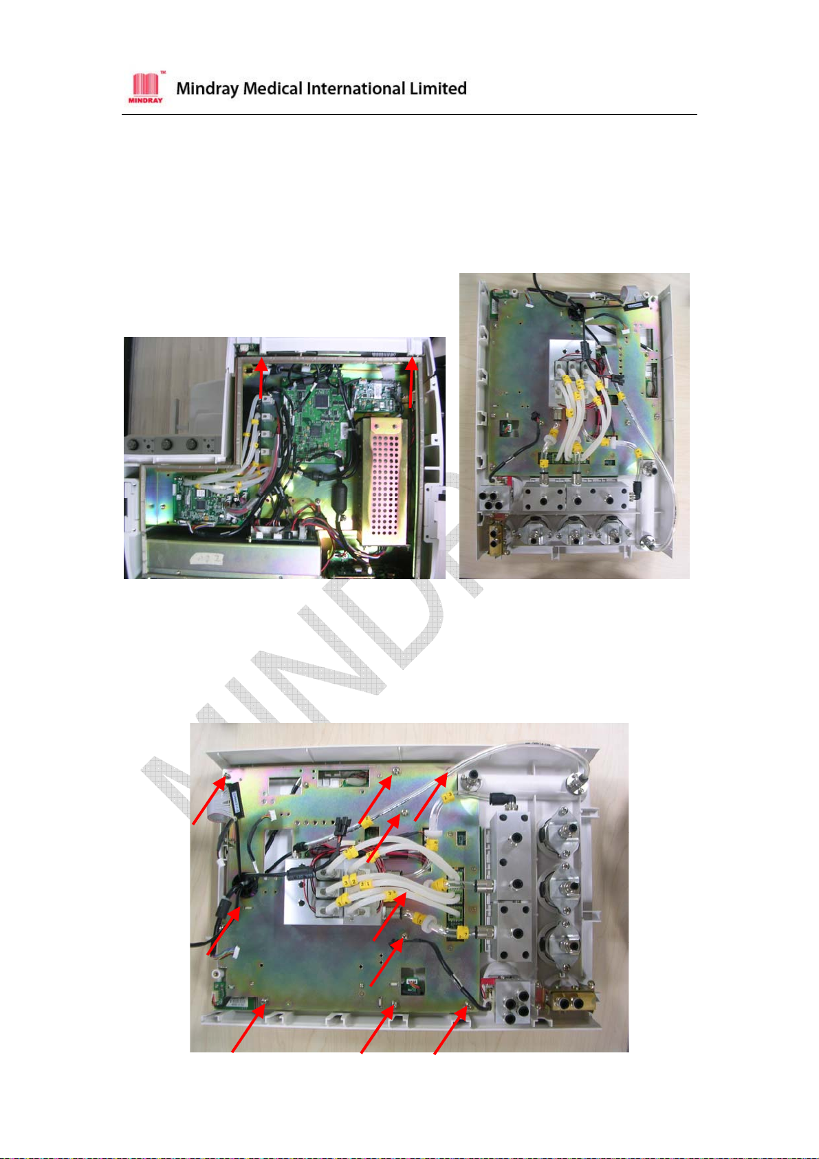
4.3 Remove the Display Assembly
★Please first finish Part 3.1, Part 4.1, Part 4.2, then:
1 Disconnect all the related cables and unscrew the ten screws shown in the picture.
- 15 -

2 Unscrew the two screws marked in the picture and take off the button board
communication cable.
3 Turn over the assembly. Disconnect the cables and unscrew the four screws marked
in the picture to remove the display.
- 16 -

4.4 Remove the High Voltage Inverter
★Please first finish Part 3.1, Part 4.1, Part 4.2, Part 4.3, then:
Unscrew the two screws and remove the high voltage inverter
4.5 Remove the System Switch
★Please first finish Part 3.1, Part 4.1, Part 4.2, then:
1 Unscrew the two screws as shown below.
- 17 -

2 Unscrew the other two screws on the other side to remove the system switch
assembly.
4.6 Remove the Flow Meter control board.
★Please first finish Part 3.1, Part 4.1, Part 4.2, Part 4.3, then:
1 Disconnect all the pipes marked in the picture.
2 Unscrew the four screws marked in the picture to remove the electronic flow meter
control board.
- 18 -

4.7 Remove the Alarm Light
★Please first finish Part 3.1, Part 4.1, Part 4.2, Part 4.3, then:
Unscrew the three screws and remove the alarm light
- 19 -

4.8 Remove the Encoder Board
★Please first finish Part 3.1, Part 4.1, Part 4.2, Part 4.3, then:
Pull out the encoder cover and then rotate the nut to remove the Encoder board.
4.9 Remove the O2 Flush Button
★Please first finish Part 3.1, Part 4.1, Part 4.2, then:
Disconnect the gas pipes and cables on the O2 flush button assembly. Then unscrew the
four screws to remove the O2 flush button assembly.
- 20 -

4.10 Remove the Pipeline or Cylinder Pressure Gauges
Each pipeline or cylinder pressure gauge can be removed alone in the same way. The
following takes AIR cylinder pressure gauge for an example.
★Please first finish Part 3.1, Part 4.1, Part 4.2, then:
1 Find the AIR cylinder pressure gauge by referring to the gauge label in the front of the
anaesthesia machine.
2 Disconnect the gas pipes from the AIR pressure gauge. Then unscrew the two
screws marked in the picture to take out the pressure gauge.
- 21 -

4.11 Remove the Flow Meter
★Please first finish Part 3.1, Part 4.1, Part 4.2, then:
Unscrew the six screws marked in the picture to remove the total flow meter.
4.12 Remove the Needle Valves
★Please first finish Part 3.1, Part 4.1, Part 4.2, then:
Unscrew the seven screws with an inner hexagon wrench and then you can take out the
needle valves.
- 22 -

4.13 Remove the Module Socket Communication Board (NIOS)
★Please first finish Part 4.1, then:
Unscrew the five screws and disconnect all the cables, take out the module socket
communication board. (The NIOS module)
4.14 Remove the Pipeline Gas Supply Inlet Assembly
★Please first finish Part 4.1, then:
Disconnect the gas pipes on the pipeline gas supply inlet assembly. Unscrew the four
screws marked in the pictures to remove the pipeline gas supply inlet assembly.
- 23 -

4.15 Disassemble the Pipeline Gas Supply Inlet Assembly
★Please first finish Part 4.1, Part 4.14, then:
1 Unscrew the four screws on the gas pipe tail fitting to remove the tail fitting.
Gas pipe connector Gas pipe support Gas pipe tail fitting
2 Replace the seal on the gas pipe tail fitting and the filter on the gas pipe connector.
Seal
Filter
- 24 -

4.16 Remove the ACGO Switch
★Please first finish Part 4.1, then:
Disconnect the gas pipes and cables on the ACGO switch assembly. Then unscrew the
three screws to remove the ACGO switch assembly.
4.17 Remove the Breathing Valve Assembly
★Please first finish Part 4.1, then:
1 Disconnect the cables and pipes from the breathing valve assembly. Then unscrew
the three screws marked in the picture.
- 25 -

2 Pull the breathing valve assembly as the direction shown in the picture to take it out.
4.18 Remove the O2-N2O block valve
★Please first finish Part 4.1, then:
Unscrew the two screws and take the O2-N2O block valve out.
- 26 -

5 Electrical and Pneumatic Diagrams
5.1 Electrical Connections
- 27 -

5.2 Pneumatic Connections
Pneumatic Connection (configured with O2, N2O and AIR supplies, high-pressure
cylinders and auxiliary O2 supply)
- 28 -

5.3 Modular Connections
- 29 -
 Loading...