


Service Manual
Datascope
Passport
®
5-Lead, 5L, LT, XG

Service Manual
Datascope
Passport
®
5-Lead, 5L, LT, XG

Table of Contents
Foreword ......................................................................................................................................v
Warnings, Precautions and Notes....................................................................................................v
Operation (5-Lead, 5L, LT and XG) ....................................................................................1 - 1
Introduction (5-Lead, 5L, LT) .......................................................................................................... 1 - 1
Controls, Indicators and Connectors (5-Lead, 5L, LT) ........................................................................ 1 - 3
Front Panel........................................................................................................................... 1 - 4
Left Side Panel...................................................................................................................... 1 - 9
Right Side Panel ................................................................................................................... 1 - 11
Remote Color Display............................................................................................................1-12
Operation (5-Lead, 5L, LT)............................................................................................................ 1 - 13
Setting-up / Turning Power On............................................................................................... 1 - 14
Factory - Default Control Settings ............................................................................................ 1 -15
Display................................................................................................................................ 1 - 16
Use of Menus....................................................................................................................... 1 - 23
Initiation of NIBP Measurements ............................................................................................. 1 - 25
ECG Acquisition................................................................................................................... 1 - 29
Invasive Pressure Acquisition.................................................................................................. 1-34
Sequence for Establishing SpO
Sequence for Establishing SpO
............................................................................................. 1 - 34
2
with Nellcor® Pulse Oximetry ................................................. 1 - 39
2
Respiration Monitoring ..........................................................................................................1-42
Gas Monitoring.................................................................................................................... 1 - 43
Alarms ................................................................................................................................ 1 - 49
How to Set the Clock............................................................................................................. 1 - 53
User Configuration Mode ...................................................................................................... 1 - 53
Recorder (optional) ............................................................................................................... 1 - 54
Status Messages................................................................................................................... 1 - 57
Monitor Problem Solving........................................................................................................ 1-62
Connection to External Devices............................................................................................... 1 - 64
Menus................................................................................................................................. 1 - 64
Introduction (XG)......................................................................................................................... 1 - 77
Controls, Indicators and Connectors (XG)....................................................................................... 1-77
Front Panel........................................................................................................................... 1 - 79
Left Side Panel...................................................................................................................... 1 - 87
Right Side Panel ................................................................................................................... 1 - 90
Rear Panel ........................................................................................................................... 1 - 91
Remote Color Display (optional) ............................................................................................. 1 - 92
Gas Module (Optional)- Front Panel ........................................................................................ 1 - 93
Gas Module (Optional)- Rear Panel......................................................................................... 1 - 95
Operation (XG)........................................................................................................................... 1 - 97
Setting-up / Turning Power On............................................................................................... 1 - 99
Factory - Default Control Settings ............................................................................................ 1 -99
Display................................................................................................................................ 1 - 102
Use of Menus....................................................................................................................... 1 - 109
Initiation of NIBP Measurements ............................................................................................. 1 - 110
ECG Acquisition................................................................................................................... 1 - 115
Invasive Pressure Acquisition.................................................................................................. 1-118
Sequence for Establishing SpO
Sequence for Establishing SpO
Sequence for Establishing SpO
............................................................................................. 1 - 119
2
with Masimo® Pulse Oximetry ................................................ 1 - 124
2
with Nellcor® Pulse Oximetry .................................................. 1 - 127
2
Respiration Monitoring ..........................................................................................................1-132
Mainstream CO
Sidestream CO
Gas Monitoring........................................................................................... 1 - 134
2
Gas Monitoring............................................................................................ 1 - 139
2
Gas Module Option.............................................................................................................. 1-146
Alarms ................................................................................................................................ 1 - 149
How to Set the Clock............................................................................................................. 1 - 153
User Configuration Mode ...................................................................................................... 1 - 153
Passport 5-Lead, 5L, LT, XG Service Manual 0070-00-0420 i

Ta ble of C onte nts
Recorder (optional) ............................................................................................................... 1 - 155
Status Messages................................................................................................................... 1 - 158
Monitor Problem Solving........................................................................................................ 1-168
Connection to External Devices (optional) ................................................................................ 1 - 172
Using the Passport XG with the Visa Central Station (optional).................................................... 1 - 172
Menus................................................................................................................................. 1 - 175
Theory of Operation.........................................................................................................2 - 1
Block Diagrams........................................................................................................................... 2 - 1
Detailed Circuit Descriptions......................................................................................................... 2 - 7
Interconnect Board................................................................................................................ 2 - 8
Frontend Board/Daughter Board ............................................................................................ 2 - 10
SpO2 Board......................................................................................................................... 2-26
CPU Board...................................................................... .............. ............... ............... ......... 2 - 40
Line Battery Board................................................................................................................. 2 - 49
+12 / -23.5 Volt Converter Board .......................................................................................... 2 - 54
Planar EL Panel Board ...........................................................................................................2-55
CO2 Interface Module .......................................................................................................... 2 -57
NIBP Module: NIBP Pneumatic Board...................................................................................... 2 - 59
Panel Board / Display Interface.............................................................................................. 2 - 63
Termination Board ................................................................................................................ 2 - 66
Specifications....................................................................................................................3 - 1
Performance Specifications........................................................................................................... 3 - 1
Power Pack Electrical Ratings........................................................................................................ 3 - 8
Environmental Conditions........................................................ .............. ....................................... 3 - 8
Physical Characteristics................................................................................................................ 3 - 8
Agency Compliance.................................................................................................................... 3 - 8
Repair Information ...........................................................................................................4 - 1
Introduction ................................................................................................................................ 4 - 1
Safety Precautions....................................................................................................................... 4 - 1
Troubleshooting Guidelines .......................................................................................................... 4 - 2
Equipment and Special Tools Required........................................................................................... 4-3
Disassembly Instructions ............................................................................................................... 4 - 3
Mounting Instructions.... .............. ............... .............. ............... .............. ............... ........................ 4 - 11
Rolling Stand Assembly Instructions......................................................................................... 4 - 11
Bedrail Hook Mount..............................................................................................................4-11
Bed Mount........................................................................................................................... 4 - 11
Passport Mounting - Rolling Stand/Wall Mount ........................................................................ 4 - 11
Power Supply Mounting......................................................................................................... 4 -11
How to Use the Remote Color Display Mounting Kit......................................................................... 4 - 15
Cable Assembly Details................................................................................................................ 4 - 16
Assembly and Schematic Diagrams...................................................................................5 - 1
Replacement Parts............................................................................................................ 6 - 1
Introduction ................................................................................................................................ 6 - 1
Available Replacement Parts and Sub-Assemblies............................................................................ 6 - 1
Product Variations and Options..................................................................................................... 6 - 1
Exchange Program...................................................................................................................... 6 - 2
Replacement Parts Pricing Information............................................................................................ 6 - 2
Ordering Information................................................................................................................... 6 - 2
Abbreviations ............................................................................................................................. 6 - 4
Calibration .......................................................................................................................7 - 1
Introduction ................................................................................................................................ 7 - 4
Warnings and Guidelines ............................................................................................................ 7 - 4
Test Equipment and Special Tools Required .................................................................................... 7 - 4
Inputs......................................................................................................................................... 7 - 4
Diagnostics and Calibration Procedure .......................................................................................... 7-5
NIBP Diagnostics.................................................................................................................. 7 - 5
ii 0070-00-0420 Passport 5-Lead, 5L, LT, XG Service Manual

Table of Contents
Error Journal ........................................................................................................................ 7 - 11
Exception Stack Frame .......................................................................................................... 7-11
Communication Test..............................................................................................................7-11
Recorder.............................................................................................................................. 7 - 14
Voltage Test......................................................................................................................... 7 - 14
Display Test ......................................................................................................................... 7 - 14
Keyboard Test...................................................................................................................... 7 - 17
Diagnostics (Datascope SpO2 Installed).......................................................................... 7 - 18
SpO
2
SpO2 Diagnostics (Nellcor SpO
SpO2 Diagnostics (Masimo SpO
Installed).............................................................................. 7 - 20
2
Installed)............................................................................. 7 - 20
2
Power-Up Verification .................................................................................................................. 7 - 20
Initial Set-Up............................................................................................................................... 7 - 21
ECG Tests .................................................................................................................................. 7 - 21
IBP1 and IBP2 Verification............................................................................................................ 7 - 23
Temperature Verification .............................................................................................................. 7 - 23
Verification........................................................................................................................ 7 - 24
SpO
2
NIBP Verification......................................................................................................................... 7 - 24
Mainstream CO2 Adapter Calibration ........................................................................................... 7 - 24
Mainstream CO
Mainstream CO
Sensor Calibration Verification...................................................................... 7 - 25
2
Sensor Calibration....................................................................................... 7 - 25
2
Sidestream Pump Calibration........................................................................................................ 7 - 26
Sidestream CO2 Pump Verification / Calibration Procedure....................................................... 7 - 27
Sidestream Adapter Calibration.............................................................................................. 7 - 28
Sidestream CO2 Sensor Calibration Verification....................................................................... 7 - 29
Sidestream CO
Sensor Calibration........................................................................................ 7 - 29
2
Battery Operation Verification....................................................................................................... 7 - 30
Leakage Current Test ................................................................................................................... 7 - 30
Cosmetic Checks......................................................................................................................... 7 - 32
Special Options Menu ................................................................................................................. 7 - 32
Preventive Maintena nce....................................................................... .............................8 - 1
Preventive Maintenance Schedule.................................................................................................. 8 - 1
Mechanical / Physical / Visual Inspection...................................................................................... 8-1
Preventive Maintenance Kit - Install Kit Annually .............................................................................. 8-1
Perform Verification and NIBP Calibration - Annually....................................................................... 8 - 2
Perform Verification and CO
Pump Calibration - Annually .......................................................... 8 - 2
2
User Preventive Maintenance Introduction....................................................................................... 8-2
Care and Cleaning of Monitor ............................................................................................... 8 - 2
Care and Cleaning of Datascope Flexisensors and Datasensors ................................................. 8 - 2
Cleaning CO
Cleaning External CO
Cleaning Internal CO
Sensors and Adapters...................................................................................... 8 - 3
2
Sampling Components......................................................................... 8 - 3
2
Sampling Components.......................................................................... 8 - 3
2
Sterilization and Cleaning of Reusable Cuffs............................................................................ 8 - 4
Battery Replacement and Maintenance.................................................................................... 8 - 5
Recorder Paper Replacement.................................................................................................. 8 - 5
Care and Storage of Thermal Chart Paper............................................................................... 8 - 5
Passport 5-Lead, 5L, LT, XG Service Manual 0070-00-0420 iii

Table of Contents
This page intentionally left blank.
Passport 5-Lead, 5L, LT, XG Service Manual 0070-00-0420 iv

Foreword Introduction
Foreword
This Service Manual is intended as a guide for technically qualified personnel during repair
and calibration procedures for the Passport 5-Lead, 5L, LT and XG monitors. The information
has been divided into the eight main sections as listed in the table of contents. A detailed
table of contents of each section is also provided on the first page of each section.
This publication may have been updated to reflect product design changes and/or manual
improvements. Any such changes to this manual would be accomplished by supply
replacement pages and instructions for inserting them into the manual.
For Passport external communication protocols (Datasette revision T or greater) see Service
Manual Supplements: P/N 0070-00-0302, Bedside-to-VISA Communication Protocol; P/N
0070-00-0304, Accutorr Communication Protocol; P/N 0070-00-0306, Passport
Communication Protocol (EzEm) and P/N 00700-00-0307, Datascope Improved ASCII
Protocol (DIAP).
NOTE: In order to ensure the proper performance of your
monitoring equipment and to prevent the voiding of the
warranty , it is recommended that only parts and accessories
provided by Datascope be u s e d with you monitor.
Warnings, Precautions and Notes
A WARNING is provided to alert the user to potential serious outcomes (death, injury, or
serious adverse events) to the patient or the user.
A CAUTION is provided to alert the user to use special care necessary for the safe and
effective use of the device. They may include actions to be taken to avoid effects on patients
or users that may not be potentially life threatening or result in serious injury, but ab out which
the user should be aware. Cautions are also provided to alert the user to adverse effects on
this device of use or misuse and the care necessary to avoid such effects.
A NOTE is provided when additional general information is applicable.
NOTE: Unauthorized servicing may void the remainder of the
warranty. Check with the factory or with a local authorized
Datascope representative to determine the warranty status
of a particular instrument.
Warnings
WARNING: The use of remote displays will enla rge all waveforms and
may alter aspec t ratios dep endin g on the remote de vice and
its set-up.
WARNING: Ensure that the conductive parts of ECG electrodes do not
contact other conductive parts including earth ground.
WARNING: Thoracic respiration measurement may inte rfer e wi th some
pacemakers. Refer to the pacemaker’s manual.
Passport 5-Lead, 5L, LT, XG Service Manual 0070-00-0420 v

Introduction W arnings, Precau tions and Notes
WARNING: Do not use the following 3-Lead ECG cables with Passport 5L
(P/N, 0998-00-0126-xx) and 5L-CE (P/N, 0998-00-0131xx): 0012-00-0620-05, -06, -07, -08; 0012-00-0722-05, 06, -07, -08; 0012-00-0723-05, -06, -07, -08; 0012-000724-05, -06, -07, -08. The above 3-Lead cables contain a
jumper wire which connects RL (right leg) to LL (left leg). As a
result, when you view aVR, aVL and aVF you will see the
appropriate ECG waveforms (even though you are using a
3-lead cable). However, there may be excessive noise on
these waveforms which can corrupt the heart rate
calculation. See Section 5 in the Operating Instructions for a
list of the proper ECG cables.
WARNING: When equipped with Nellcor ® SpO
, use only Nellcor®
2
oxygen transducers including Nellcor® OXISENSOR™
patient dedicated adhesive sensors. Use of other oxygen
transducers may cause improper oximete r pe rform ance.
WARNING: Tissue damage or inaccurate measurements may be caused
by incorrect sensor application or use, such as wr apping it
too tightly, app lying supplemental tape, failing to inspect
the sensor site periodically, or failing to position it
appropriately. Carefully read the sensor directions for use,
the Passport operating instructions, and all precautionary
information before use .
WARNING: Excessive ambient light may cause inaccurate
measurements. Cover the sensor site with opaque materi al.
WARNING: Inaccurate measurements may be caused by incorrect
sensor application or use; significant levels of dysfunctio nal
hemoglobins, (e.g., carboxyhemoglobin or methemoglobin);
or intra-v ascul ar dy es such as i ndocy anine green methyl ene
blue; exposure to excessive illumination, such as surgical
lamps (especially ones with a x enon light source), bilirubin
lamps, fluorescent lights, infrared heating lamp s, o r dire ct
sunlight; excessive patient movement; venous pulsations;
electro-surgi cal interference; and placement of a sensor o n
an extremity that has a blood pressure cuff, arterial
catheter, or intra-vascular line.
WARNING: In certain situations in which perfusion and signal strength
are low, such as in patients with thick or pigmented skin,
inaccurately low SpO
readings will result. Verification of
2
oxygenation should be made, especially in preterm infants
and patients with chronic lun g disease, before instituting
any therapy or intervention.
WARNING: Insure that the conductive parts of ECG electrodes do not
contact other conductive parts including earth ground.
WARNING: Many patients suffer from poor peripheral perfusion due to
hypothermia, hypovolem ia, se vere vasoconstriction,
reduced cardiac output, etc. These symptoms may cause a
loss in vital sign readings.
vi 0070-00-0420 Passport 5-Lead, 5L, LT, XG Service Manual

Introduction W arnings, Precau tions and Notes
WARNING: The site should be checked at least every eight (8) hours
(every four (4) hours with the Adult re-usable finger sensor).
Ensure proper adhesion, skin integrity, and proper
alignment. Nail polish and fungus may effect readings.
Exercise ex t r eme caution with poorly perfused pa t i ents.
Skin erosion and pressure necrosis can be caused when
sensors are not frequently monitored. Assess the site ev ery
two (2) hours with poorly perfused patients.
WARNING: Do not use the following 3-Lead ECG cables with Passport
XG (P/N’s 0998-00-0133-xx, 0998-00-0134-xx and 099800-0137-xx): 0012-00-0620-05, -06, -07, -08; 0012-000722-05, -06, -07, 08; 0012-00-0723-05, -06, -07, -08;
0012-00-0724-05, -06, -07, -08. The above 3-Lead cables
contain a jumper wire which connects RL (right leg) to LL (left
leg). As a result, when you view aVR, aVL and aVF you will
see the appropriate ECG waveforms (even though you are
using a 3-lead cable). However, there may be excessive
noise on these waveforms which can corrupt the heart rate
calculation. See Section 5 in the Datascope P/N’s 0070-00397, 0070-00-0440, 0070-00-0503 of the Passport
Operating Instructions for a list of the proper ECG cables.
WARNING: If the sensor or patient cable is damaged in any way,
discontinue use immediately. To prevent damage do not
soak or immerse the sensor in any liquid solution. Do not
attempt to sterilize.
WA RNING: The maxim um sa mplin g ra te at the nasa l ca nnula i s 2 00 ml /
min. This device should not be used on patients whose
breathing could be impaired by this vac u um flow rate.
WARNING: Connection of the Passport’s exhaust port to the hospital’s
waste gas scavenge system is recommended to prevent
exposure of hospital personnel to the patient’s respiratory
sample.
WARNING: In an intubated configuration, ensure all tubing connections
are tight. If tubing disconnects on the monitor side of the
airway adapter, ventilator pressures cause inaccurate CO
2
waveforms and readouts to be displayed.
WA RNING: The maxim um sa mplin g ra te at the nasa l ca nnula i s 2 00 ml /
min. This device should not be used on patients whose
breathing could be impaired by this vac u um flow rate.
WARNING: Connection of the Gas Module exhaust port (50) to the
hospital’s waste gas scavenge system is stro ngly
recommended to prevent exposure of hospital personnel to
the patient’s respiratory sample. Vacuum (negative
pressure) should not exceed 1 mmHg at the Gas Module
Pump Exhaust fitting (50). Excessive scavenge vacuum may
result in damage to the Gas Module’s internal pum p.
vii 0070-00-0420 Passport 5-Lead, 5L, LT, XG Service Manual

Warnings, Precautions and Notes Introduction
Cautions
CAUTION: Connection of non-isolated devices to the optional RS232
Connector on this unit may cause chassis leakage to exceed
the specification standards.
CAUTION: Only use the Abbreviated Operating Check List if you are
CAUTION: Alway s at t a c h al l desired peripher al e qui pment prior to
CAUTION: Observe extreme cauti on on all patien ts (n eon a t es,
CAUTION: It is the users responsibility to confir m co rrect operation of
already familiar with this product. If not, please continue
with the remainder of this chapter, Detailed Operating
Instructions.
powering on the Passport. If required to attach more or
change what is connected, turn the Passport off, attach
what is needed, and then turn the Passport on again.
pediatrics, and adults) when NIBP is set to the Continuous
Mode. A 5 minute limit is placed on continuous
measurements. After 5 minutes the unit will take a
measurement once every 5 minutes. Reports have been
made of nerve injury occurring during use of automatically
cycled blood pressure cuffs. See the Appendix, “Precautions
when Using Automatically Cycled Blood Pressure
Cuffs”.Observe extreme caution on all patients (neonates,
pediatrics, and adults) when NIBP is set to the Continuous
Mode. A 5 minute limit is placed on continuous
measurements. After 5 minutes the unit will take a
measurement once every 5 minutes.
Reports have been made of nerve injury occurring during
use of automatically cycled blood pressure cuffs. See the
Appendix, “Precautions when Using Automatic ally Cycl ed
Blood Pressure Cuffs”.
the Passport with external devices. It is essential that a
biomedical engineer verify correct operation of the Passport
with an external device. Testing should include verification
that the maximum delay for cardioversion synchronization
does not exceed 60 ms (mon itor an d defibrillator). Cable
should be labeled with the devices they have been te sted
for use with.
CAUTION: Do not use this special “Y” shap ed power cable for any
devices other than the Passport and Gas Module II.
CAUTION: Vacuum (negative pressure) should not exceed 1 mmHg at
the Passport Pump Exhaust fitting (39). Excessive scavenge
vacuum may result in an “OCCLUSION” message or
damage to the Passport’s internal pump. The scavenge
system if used must be on during calibrati on.
CAUTION: It is the users responsibility to confir m co rrect operation of
Passport 5-Lead, 5L, LT, XG Service Manual 0070-00-0420 viii
the Passport XG with external devices. Before using this
cable it is essential that a biomedical engineer verify correct
operation of the Passport XG with an external device using
this cable. Testing should include verification that the
maximum delay for cardioversion synchronization does not
exceed 60 ms (monitor and defibrillator). Cable should be
labeled with the devices they have been tested for use with.

Introduction W arnings, Precau tions and Notes
CAUTION: When cleaning sensors do not use excessive amounts of
liquid. Wi pe the sensor surface with a soft cloth, dampened
with the cleaning solution.
CAUTION: Using dark colored soaks may stain the cuffs. Test a single
cuff to ensure that no damage will occur. ETO sterilization
may also be used.
CAUTION: When ironing o r pre ssin g the cuffs, be aware that the
Velcro® fasteners can melt at temperatures above 325°F,
162°C.
ix 0070-00-0420 Passport 5-Lead, 5L, LT, XG Service Manual

Introduction W arnings, Precau tions and Notes
This page intentionally left blank.
x 0070-00-0420 Passport 5-Lead, 5L, LT, XG Service Manual

1.0
Operation (5-Lead, 5L, LT and XG)
Contents of this Chapter ..................................................Page
1.1 Introduction (5-Lead, 5L, LT) ..................................... 1-1
1.2 Controls, Indicators and Connectors (5-Lead, 5L, LT) . 1-3
1.3 Operation (5-Lead, 5L, LT) ........................................ 1-13
1.4 Introduction (XG) ..................................................... 1-77
1.5 Controls, Indicators and Connectors (XG) ................. 1-77
1.6 Operation (XG) ........................................................ 1-97
1.1 In troduction (5-Lead, 5L, LT )
This section of the Service Manual provides general information about the Datascope
Passport Monitors 5-Lead, 5L and LT. All functions, standard and optional, are described in
this section. The pictures of the unit and the displays should be used as samples and may not
be exactly as your unit appears. Table 1-1 on page 1-2 lists the functions available on the
Passport 5-Lead/5L and the Passport LT.
Passport 5-Lead, 5L, LT, XG Service Manual 0070-00-0420 1 - 1

Introduction (5-Lead, 5L, LT) Operation (5-Lead, 5L, LT and XG)
TABLE 1-1
PASSPORT 5L PASSPORT LT
FUNCTIONS* STANDARD OPTIONAL STANDARD OPTIONAL
NIBP
••
IBP
ECG
SpO2 - Datascope
SpO2 - Nellcor
Respiration
CO
2
Recorder
Temperature
* For detailed instructions of each function see the Table of Contents for sections and page numbers.
NOTE: Sections 1.2 and 1.3 are included as a review of instrument
functions and operation, although the reader is encouraged
to refer to the Operating Instructions, P/N 0070-00-0324,
for more complete details.
••
••
••
••
••
•
•
••
1 - 2 0070-00-0420 Passport 5-Lead, 5L, LT, XG Service Manual

Operation (5-Lead, 5L, LT and XG ) Controls, Indicators and Connectors (5-Lead, 5L, LT)
1.2 Controls, Indicators and Connectors (5-Lead, 5L, LT)
The keys on the front panel of the Passport Monitor are classified as single action, repeat
action, or delayed action keys.
A single action key provides one action each time it is pressed, regardless of how long it is
held.
A repeat action key provides the an action when pressed, then waits half a second before
repeating the action until the key is released.
A delayed action key provides an action, but only after the key has been held pressed for a
(key specific) period of time.
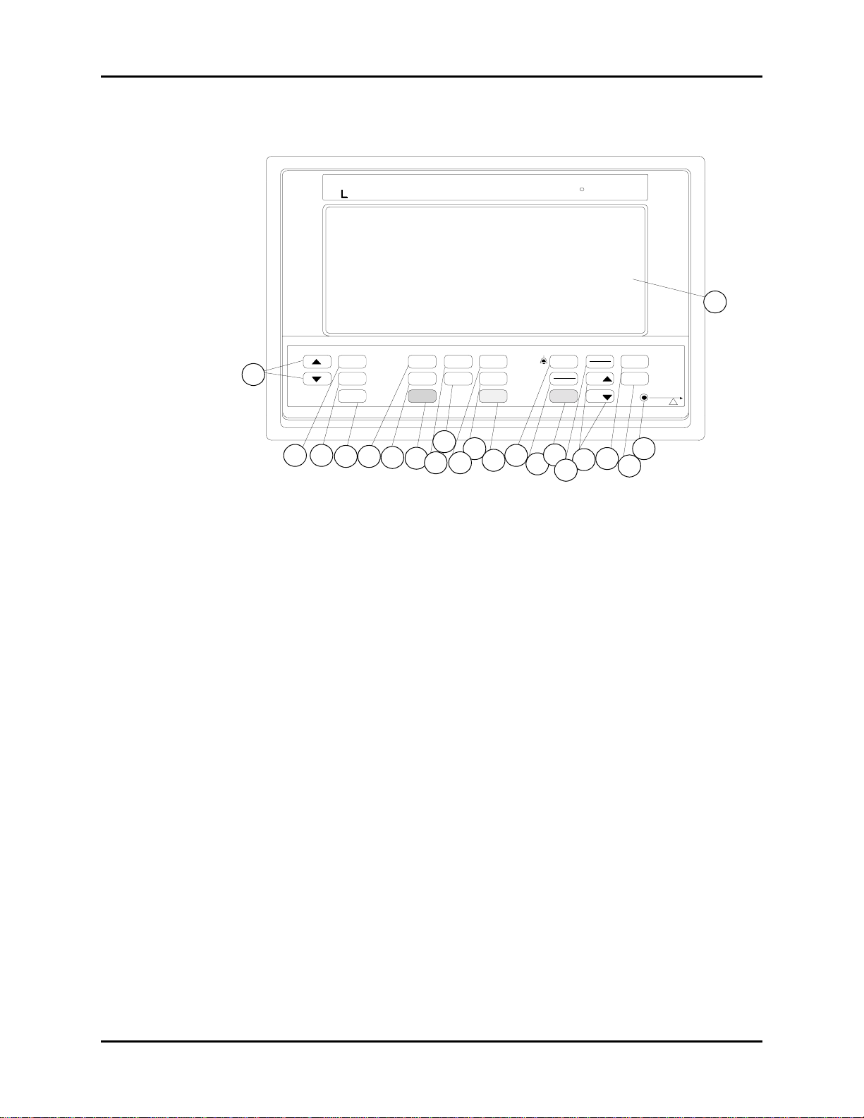
1. p and q (Set-up) 8. ZERO 1 (IBP) (Opt ional15. MUTE (Alarms)
2. SELECT (Set-up) 9. ZERO 2 (IBP) (Optional)16. TREND/RETURN (Trends)
3. END (Set-up) 10. START (NIBP) 17. TIME UP p and DOWN
q (Trends)
4. CENTRAL SILENCE
(Optional)
5. LEAD (ECG) 12. DEFLATE (NIBP) 19. RECORD (Optional)
6. SIZE (ECG) 13. VOL UM E (A larms) 20. DC INPUT
7. FREEZE (ECG) 14. CHECK/RETURN
11. INTERVA L (NIBP) 18. BEEP VOLUME
21. DISPLAY
(Alarms)
PARAGRAPH
NUMBER DESCRIPTION
1.2.1 Front Panel 1 - 21 1-4
1.2.2 Left Side Panel 22 - 30 1-9
1.2.3 Right Side Panel 31 - 34 1-11
1.2.4 Remote Color Display 1-12 12 - 14
CONTROL/DISPLAY
NUMBER
PAGE
NUMBER
Passport 5-Lead, 5L, LT, XG Service Manual 0070-00-0420 1 - 3
Controls, Indicators and Connectors (5-Lead, 5L, LT) Operation (5-Lead, 5L, LT and XG)
1.2.1 Front Panel
R
ALARMS
VOLUME
CHECK
RETURN
MUTE
15
16
Passport
TRENDS
TREN D
RETURN
TIM E
TIME
17
12
13
Datascope
14
5
SET-UP
SEL ECT
1
1
2 3
2 3 4 5 6 7 8 9 10 11 12 13 14 15 16 17 18 2019
END
CENTRAL
SILENCE
4 5
ECG IBP NI BP
LEAD
SIZ E
FREEZE
6
7
ZERO 1
START
ZERO 2
INTE RVAL
DEFLAT E
9
11 20
8 10
18
BEEP
VO LUM E
RECORD
19
TM
D.C. INPUT
MODEL
EL
!
FIGURE 1-1 Front Panel Controls
Introduction
The keys on the front panel of the Passport Monitor are classified as single action, repeat
action, or delayed action keys.
21
21
A single action key provides one action each time it is pressed, regardless of how long it is
held.
A repeat action key provides the an action when pressed, then waits half a second before
repeating the action until the key is released.
A delayed action key provides an action, but only after the key has been held pressed for
a (key specific) period of time.
NOTE: Only one key function will be recognized a t any time. The
Passport will ignore multiple key se lections.
All key actions are acknowledged by a key click, except for BEEP VOL and ALARM VOL. If a
key is not available a double key click will sound.
1. p and q (UP and DOWN) (Set-Up)
Two repeat action keys used to move the highlighted screen cursor or change the setting/
value of a menu item. As the cursor is moved, the highlighted menu window is displayed.
2. SELECT (Set-Up)
A repeat action key used to select the function or value indicated by the highlighted cursor.
1 - 4 0070-00-0420 Passport 5-Lead, 5L, LT, XG Service Manual

Operation (5-Lead, 5L, LT and XG ) Controls, Indicators and Connectors (5-Lead, 5L, LT)
3. END (Set-Up)
A single action key which causes the display to return to the main screen display (as
specified in the DISPLAY section). This key is always available.
4. CENTRAL SILENCE (Optional)
A single-action k ey which m utes the a larms of the c orrespon ding cha nnel on the VISA Centra l
Station. The amount of time the alarms are silenced, is determined by the VISA.
5. LEAD (ECG)
A single action key which selects the ECG lead to be displayed. Each depression of the key
selects and displays the next ECG lead from the list. The list wraps around after the last entry
is selected. Choices are: I, II, III, aVR, aVL, aVF or V.
6. SIZE (ECG)
A single action key which selects the ECG size to be displayed. Each depression of the key
selects and displays the next ECG size from the list. The list wraps around after the last entry
is selected.
7. FREEZE (Screen)
A single action key which enables or releases the screen freeze function. The freeze key
stops or starts the ECG waveform (waveform 1), except when waveform 2 is used for
cascaded ECG. When this is the case, pressing the freeze key the f irst time causes the
currently displayed ECG waveform data to be transferred to waveform 2 and frozen.
Waveforms 1 and 3 continue to move. Pressing FREEZE again causes waveform 2 to return
to cascaded ECG.
8. ZERO 1 (IBP) (Optional)
A delayed action key which zeros the current pressure in the BP1 channel. If the transducer
zero process is unsuccessful, “UNABLE TO ZERO” is displayed in the window containing BP
value. This key is only available when a pressure transducer is present.
9. ZERO 2 (IBP) (Optional)
A delayed action key which zeros the current pressure in the BP2 channel. If the transducer
zero process is unsuccessful, “UNABLE TO ZERO” is displayed in a temporary window
within the parameter window. This key is only available when a pressure transducer is
present.
10. START (NIBP)
A single action key which initiates an NIBP measurement. This function is not available if a
measurement is in progress.
11. INTERVAL (NIBP)
A repeat action key which selects the interval setting for NIBP measurements. Values wrap
around at the lowest/highest choices. Choices are: Off, Continuous, 1, 2.5, 5, 10, 15, 20,
30, 60, and 120 minutes. Five seconds after the selection is made and the key is released,
the new interval takes effect.
Passport 5-Lead, 5L, LT, XG Service Manual 0070-00-0420 1 - 5

Controls, Indicators and Connectors (5-Lead, 5L, LT) Operation (5-Lead, 5L, LT and XG)
12. DEFLATE (NIBP)
A single action key which stops any NIBP measurement in progress, including any timed
measurement sequence, and deflates the cuff. When a timed measurement is stopped an
“NIBP: DEFLATE” message followed by an “NIBP: IDLE” message displays in the NIBP
message window until the timer mode is restarted by either pressing START or changing the
interval.
13. VOLUME (Alarms and Alarm LED)
A repeat action key which adjusts the alarm volume in 5 steps. There is no off position for this
tone. The tone wraps to the minimum volume once the maximum is reached. The red alarm
bell LED illuminates when an alarm condition exists. Refer to “Alarms” on page 1-49.
14. CHECK/R ET UR N (Alarms)
A single action key which provides access to the alarm menu to view and select alarm
values. Press SELECT to change the alarm values. Pressing CHECK/RETURN a second time
or the END key, returns the display to the main screen and exits the alarm menu.
15. MUTE (Ala rms)
A single action and delayed action key which silences all currently alarming parameters or
suspends all alarms. A single key press will silence the current alarm tone for 2 minutes. Any
new alarms that occur while the alarm tone is muted will disable the mute and sound the
Alarm Mute
Symbol
alarm tone. An alarm mute symbol is displayed next to each muted parameter. The word
Mute is displayed above the menu selections.
When the key is pressed and held for 3 seconds, all set alarms will be suspended for 2
minutes. This is indicated by the Alarm Mute Symbol and the words All Mute displayed
above the menu selections.
When “Aud alm standby” is set to ON (in the User Configuration Menu), and the MUTE key
is pressed and held for 4 seconds, all alarms are indefinitely suspended. This is indicated by
the Alarm Mute Symbol in all parameter windows and the words Aud Alm Sby flashing
above the menu selections.
The All Mute and Aud Alm Sby modes can be exited by pressing the mute key.
NOTE: When “Aud alm standby” is set to ON and the unit is power
off and then on again, the unit will power up in the Aud alm
standby mode.
16. TRENDS/RETURN (Trends)
A single action and delayed action key which displays and clears trended data. The most
recent page of data is displayed when the key is first pressed. Press this key a second time to
view additional trended data. Pressing and holding the key for 3 seconds clears all trended
data.
17. TIME UP p and q TIME DOWN (Trends)
Two repeat action keys which are used to scroll through the trend data.
1 - 6 0070-00-0420 Passport 5-Lead, 5L, LT, XG Service Manual

Operation (5-Lead, 5L, LT and XG ) Controls, Indicators and Connectors (5-Lead, 5L, LT)
18. BEEP VOLUME
A repeat ac ti o n k ey w h ich ad j us ts th e bee p v ol u me in 5 s te ps plu s OFF. Wh en t h e m axi mu m
volume is reached, the volume will wrap around to OFF , then to the minimum volume
19. RECORD (Optional)
A combination single action and delayed action key which initiates or stops a recording.
Pressing the key once in itiates a printout. Holding the key pressed for three seconds, when
waveforms are displayed, initiates a continuous printing of waveforms. Pressing the key
while the printing is in progress, stops the recorder. The recorder prints either waveforms or
trend data, depending on what is displayed (i.e. trend data is printed when trend list is
displayed.). The Recorder Set-up will determine which waveform or waveforms are printed.
The Recorder Set-up will also determine the Record Destination - Local (recording from th e
Passport), Remote (recording from the VISA, no recording from the Passport), or Both
(recording from the Passport and VISA).
NOTE: When a remote (VISA) recordin g is printe d, the information
that is printed is determined by the set-up in the VISA.
20. DC INPUT
A green LED used to indicate that the POWER Switch (33) is in the ON position.
MENU
AREA
FIGURE 1-2 Display
ECG AREA
PARAMETER
AREA
MULT I-FUNCTION AREA
MESSAGE AREA
Passport 5-Lead, 5L, LT, XG Service Manual 0070-00-0420 1 - 7

Controls, Indicators and Connectors (5-Lead, 5L, LT) Operation (5-Lead, 5L, LT and XG)
21. DISPLAY
The Display is used to present information which is divided into 5 graphic display areas.
They are:
A. MENU Display Area
B. ECG Display Area
C. PARAMETER Display Area
D. MULTI-FUNCTION Display Area
E. MESSAGE Display Area
NOTE: Only one key function will be recognized a t any time. The
Passport will ignore multiple key se lections.
1 - 8 0070-00-0420 Passport 5-Lead, 5L, LT, XG Service Manual
Operation (5-Lead, 5L, LT and XG ) Controls, Indicators and Connectors (5-Lead, 5L, LT)
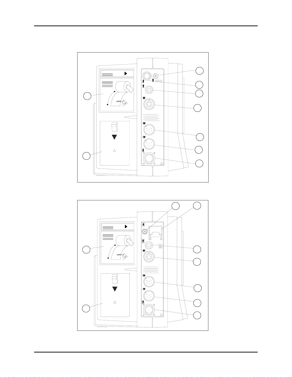
1.2.2 Left Side Panel
SpO
CUFF
2
o
T
ECG /EK G
E.S.I.S.
All Patient Connections
Electrica lly Isolat e d
IBP 1
PI 1
IBP 2
PI 2
CO
2
!
22
23
23
Press to Open
Replace only with:
10cm
22
BATT.
!
FIGURE 1-3 Left Side Panel with Datascope SpO
2
24 25
24
27
25
25
26
27
28
29
29
30
24
24
25
26
30
28
Press to Op en
Replace only with:
10cm
22
22
BATT.
!
23
23
FIGURE 1-4 Left Side Panel with Nellcor® SpO
CUFF
o
T
ECG /EKG
All Patie nt Co nnections
Electrica lly Isolate d
E.S.I.S.
IBP 1
PI 1
IBP 2
PI 2
CO
SpO
2
26
26
27
27
28
28
29
2
!
29
30
30
2
Passport 5-Lead, 5L, LT, XG Service Manual 0070-00-0420 1 - 9

Controls, Indicators and Connectors (5-Lead, 5L, LT) Operation (5-Lead, 5L, LT and XG)
22. RECORDER (Optional)
A two trace thermal strip chart recorder with integral paper spool.
23. BATTERY PACK
Two internal, user replaceable, rechargeable, sealed lead acid batteries that provide power
to operate the monitor when not connected to the power pack. The battery packs may be
removed and replaced independently while the unit is operating.
24. CUFF
A connector used to attach the NIBP cuff assembly to the monitor.
25. SpO
2
An 8-pin DIN type or 9-pin sub miniature D (Nellcor) type female connector used to attach
O
the Sp
sensor assembly to the monitor.
2
26. T (Temperature)
A standard three wire phone jack used to mate with either the YSI series 400 or 700*
temperature probes. The Passport automatically identifies which probe is connected.
27. ECG / EKG
A six-pin AAMI (ECG-D10/75) standard connector (AMP P/N 864900-1; Datascope P/N
0131-00-0079) used for patient cable connections.
*Feature applicable only if available installed in your unit.
28. IBP1 (Optional)
A six-pin male connector (Datascope P/N 0131-00-0094) used for Datascope specified
pressure transducers listed in Chapter 5, Accessories.
29. IBP2 (Optional)
A six-pin male connector (Datascope P/N 0131-00-0094) used for Datascope specified
pressure transducers listed in Chapter 5, Accessories.
30. CO
A 20 pin connector used to attach the CAPNOSTAT C
(Optional)
2
O
sensor to the monitor.
2
1 - 10 0070-00-0420 Passport 5-Lead, 5L, LT, XG Service Manual
Operation (5-Lead, 5L, LT and XG ) Controls, Indicators and Connectors (5-Lead, 5L, LT)
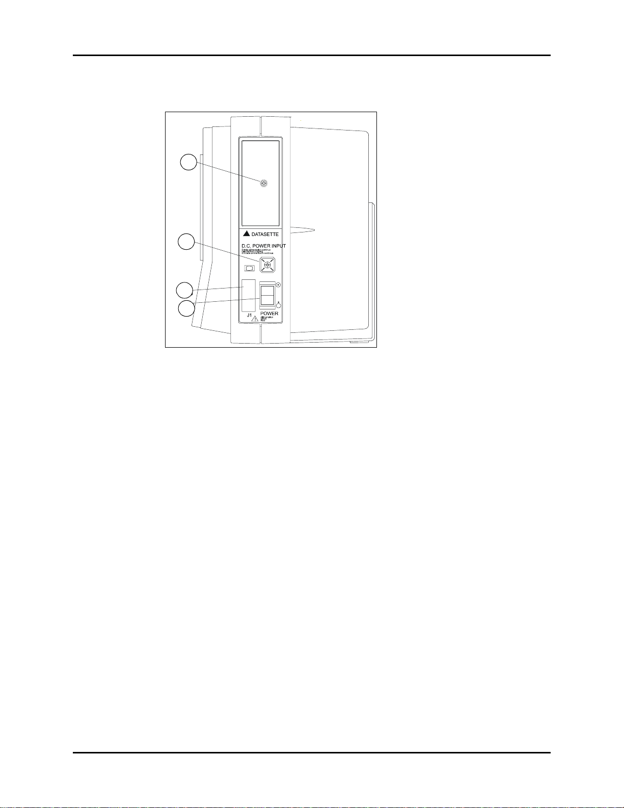
1.2.3 Right Side Panel
31
32
33
34
FIGURE 1-5 Right Side Panel
31. DATASETTE
A user replaceable software cartridge used for installing updated software revisions.
32. DC POWER INPUT (CONNECTOR)
A four terminal connector to supply low voltage DC power to the unit and charge the
batteries. The power pack provides power to the unit independent of battery installation.
33. J1
A communication interface connector used to conn ect the Passport to a VISA Central Station
Monitor, Remote Color Display, Nurse Call, DPD Defibrillator or other peripheral devices.
34. POWER
A recessed rocker switch which interrupts power to the main unit but does not prevent
charging of the batteries.
Passport 5-Lead, 5L, LT, XG Service Manual 0070-00-0420 1 - 11
Controls, Indicators and Connectors (5-Lead, 5L, LT) Operation (5-Lead, 5L, LT and XG)
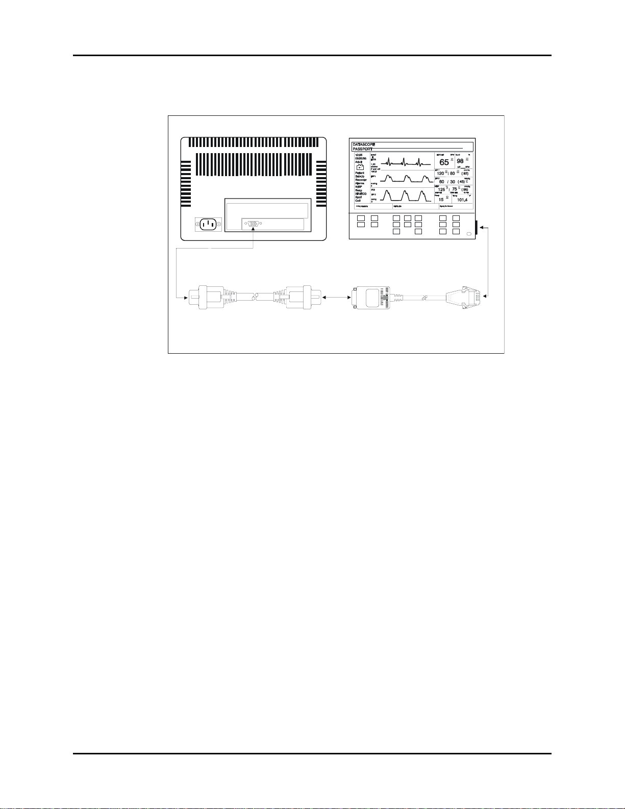
1.2.4 Remote Color Display
REMOTE COLOR DISPLAY, REAR
Remote Color Display Interface Cable
P/N 0012-00-0994
1. Connect Interface cable,
P/N 0012-00-0994, to the Analog
Input connector on the Remote
Color Display.
2. Connect PASSPORT M onitor
Video Interface cable,
P/N 0012-00-0983. to the Remote
Color Display Interface cable,
P/N 0012-00-0994.
PASSPORT MONITOR , F RONT VIEW
assport Video Interface Cable
P
P/N 0012-00-0983
3. Connect the PASSPORT
Monitor Video Interface Cable to
J1 on the PASSPORT Monitor
FIGURE 1-6 Remote Color Display
For instructions on mounting the remote display to a wall, refer to Operating Instructions.
WARNING: The use of remote displays will enla rge all waveforms and
may alter aspec t ratios dep endin g on the remote de vice and
its set-up.
1 - 12 0070-00-0420 Passport 5-Lead, 5L, LT, XG Service Manual

Operation (5-Lead, 5L, LT and XG ) Operation (5-Lead, 5L, LT)
1.3 Operation (5-Lead, 5L, LT)
Abbreviated Operating Check List
CAUTION: Only use the Abbreviated Operating Check List if you are
already familiar with this product. If not, please continue
with the remainder of this chapter, Detailed Operating
Instructions.
A. Setting-Up
1. Set POWER switch to OFF.
2. Connect, if desired, peripheral equipment (i.e., Remote Color Display, P.C., etc.).
3. Attach power pack and/or install charged batteries as needed.
4. Set POWER switch to ON.
5. Using the menus and keyboard, set (when appropriate) the following:
--
• Patient Size and Trend Clear • HR Information
• Set Up Information (speed, waveform • Sp
O
Information 2 and 3, etc.)
2
• ECG Information • Recorder Information (when available)
• Resp. Information • Alarm Limits
• Alarm Volume • NIBP Information
•Beep Volume •IBP Information
B. Initiating an NIBP Measurement
1. Select cuff.
2. Attach cuff hose to NIBP connector and place cuff on patient.
3. Select timer interval, if desired.
4. Select cuff pressure, if necessary.
5. Press START to begin an NIBP measurement.
6. Press DEFLATE to suspend measurement.
C. Establishing SpO
2
1. Select the appropriate sensor.
2. Attach sensor to Sp
3. Set either waveform 2 or 3 in the set-up menu to display the Sp
Passport 5-Lead, 5L, LT, XG Service Manual 0070-00-0420 1 - 13
O
connector and apply to the patient.
2
O
waveform, if desired.
2

Operation (5-Lead, 5L, LT) Operation (5-Lead, 5L, LT and XG)
D. Establishing CO2 / CAPNOSTAT*
1. Plug sensor into the side of the monitor.
2. If a new CAPNOSTAT is used, calibrate the system.
3. Apply sensor to the breathing circuit.
4. Set Waveform 2 or 3 to CO
5. Set the Resp. Source to CO
* CAPNOSTAT is a tra demark of NOVAMETRIX, Inc.
.
2
.
2
E. Recording Information
1. Select wave to be recorded through Record Menu or if desired to record tabular trend,
press TREND/RETURN.
2. Press Record to start recording function.
3. Press Record again to stop the recording function.
F. Temperature Measurement
1. Attach the desired temperature probe to the Temperature connector on the side of the
Passport. The Passport automatically detects which probe is connected, 400 or 700
series.
Detailed Operating Instructions
This section of the Service Manual provides guidelines and step-by-step instructions for
proper operation of the monitor. Numbers in parentheses ( ) relate to the displays and
controls described in “Controls, Indicators and Connectors (5-Lead, 5L, LT)” on page 1-3
1.3.1 Setting-up / Turning Power On
1. Set the POWER switch (34) to OFF.
2. Attach any peripheral equipment, i.e., Visa Central Station, Remote Color Display.
CAUTION: Always attach all desired peripheral equipment pr ior to
3. Attach the power pack to the DC POWER INPUT connector (32). If battery operation is
required, ensure that two fully charged batteries are installed.
NOTE: If power pack is connected ensure that the screw is
4. Set the POWER switch (34) to ON.
Internal self tests will run and the display will come on. A “DIAGNOSTIC IN
PROGRESS” message will display and once the self tests have been completed a “SELF
TEST COMPLETE” message will display. After this the main screen is displayed.
If any failures occur, see “Status Messages” on page 1-57 for further instructions.
powering on the Passport. If required to attach more or
change what is connected, turn the Passport off, attach
what is needed, and then turn the Passport on again.
tightened so that the cord does not detach.
1 - 14 0070-00-0420 Passport 5-Lead, 5L, LT, XG Service Manual

Operation (5-Lead, 5L, LT and XG ) Operation (5-Lead, 5L, LT)
1.3.2 Factory - Default Control Settings
The following are the factory initial (default) control settings. This is the state that the unit will
power up in unless a “current configuration” has been saved from the set up menu.
TAB LE 1- 2 Default Settings
MENU FUNCTION DEFAULT SETTINGS
Patient Size Adult
Clear Trend Memory No
Pacer Enhanc ement Off
Set-up Speed 25 mm/sec.
Resp Speed 12.5 mm/sec.
Waveform 2 Cascade ECG
Waveform 3 Pleth
Resp Source ECG
Powerup Settings No change
Record Wave Selection ECG
Record on Alarm No
Recorder Destination Local
Alarms Low High
Heart Rate Off Off
SpO
2
IBP1 Sys Off Off
IBP1 Dia Off Off
NIBP Sys Off Off
NIBP Dia Off Off
IBP2 Mean Off Off
Resp Rate Off Off
Apnea Delay Off Adult, Off Ped., 10 se c
ETCO
2
NIBP Start Pressure 180 mmHg Adult, 140 mmHg
IBP IBP1 Scale Range 150 mmHg
IBP2 Scale Range 37.5 mmHg
Respiration Scale 3 cm/ohm
HR Source Auto
SpO
2
CO
2
Trend Trigger NIBP
ECG Lead II
NIBP Interval Off
Volume Beep Off
Pleth Scale* 3
Scale Range 40 Torr
Interval Timer 5 min
Size 1 cm/mV
Alarm 1
85 Off
Neonate
Off Off
Ped., 120 mmHg Neonate
Passport 5-Lead, 5L, LT, XG Service Manual 0070-00-0420 1 - 15

Operation (5-Lead, 5L, LT) Operation (5-Lead, 5L, LT and XG)
TAB LE 1-2 D ef au lt Settings (Continued)
MENU FUNCTION DEFAULT SETTINGS
Temperature Scale ºF**
HrSpO
Audio Alarm de lay Audio Alarm delay Off
Aud alm stand by Aud alm standby Off
Serial Output T ype Serial Output Type Visa
Changes can be made and saved to these default settings. The default settings can also be
restored. Refer to “Setting-up / Turning Power On” on page 1-14.
* If your unit is equipped with Nellcor® SpO2, there is no pleth scale adjustment. This is replaced with operat-
** Farhenheit is the default setting for English units only. All other language units default to Centigrade.
Size Hr SpO2 Size HR small, SpO2 large
2
ing mode options 1, 2, and 3.
1.3.3 Display
ECG AREA
MENU
AREA
PARAMETER
AREA
MUL TI-FUNCTION AREA
MESSAGE AREA
FIGURE 1-7 Window Layout
The Display is divided into five graphic areas as shown above.
MENU Display Area - displays the main menu selections available with the cursor and
select keys, the battery symbol and the mute categories.
ECG Display Area - displays the ECG trace, ECG information and pacer enhancement
status.
P ARAM ET ER Display Area - displays the current values of patient parameters.
1 - 16 0070-00-0420 Passport 5-Lead, 5L, LT, XG Service Manual
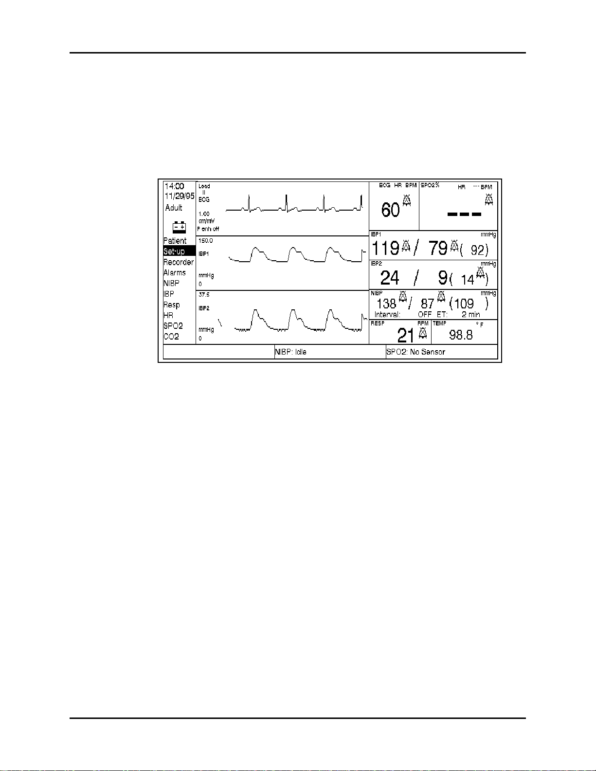
Operation (5-Lead, 5L, LT and XG ) Operation (5-Lead, 5L, LT)
MULTI-FUNCT I ON Display Area - displays additional waveforms and temporary boxes
for menu functions.
MESSAGE Display Area - displays messages relating to NIBP, SpO2, CO2 and recorder
operation.
1.3.3.1 Menu Display Area
FIGURE 1-8 Window Layout
The menu area displays the main menu selections available. These are accessed by using the
UP p and DOWN q arrow keys (1) and SELECT (2) set-up keys. One of the menu item is
always highlighted by the cursor. This window also contains the TIME, DATE, PATIENT SIZE
and MUTE CATEGORY (when active) information.
For each patient size available there are different choices within the menu selections.
T able 1-3 on page 1-18 indicates the choices for each menu set-up and also where there are
different selections for each patient size.
A list of all menus and the selections available is provided in T able 1-2 on page 1-15. For a
graphic representation of each of these menus, see “Use of Menus” on page 23.
NOTE: The “IBP”, “Recorder” and “CO2” menu items only appear
only on models equipped with these options.
NOTE: The display sample shown above may not be an exact
representation of your unit.
Passport 5-Lead, 5L, LT, XG Service Manual 0070-00-0420 1 - 17

Operation (5-Lead, 5L, LT) Operation (5-Lead, 5L, LT and XG)
TABLE 1-3 Menu List
MENU
LIST MENU ITEM CHOICES
Patient Size Adult, Pediatric, Neonate
Clear Trend Memory No, Yes
Pacer Enhancement On, Off
Setup Speed 12.5, 25, 50 mm/sec.
Resp Source Off, ECG, CO
Resp Speed 3.125, 6.25, 12.5, 25 mm/sec.
Waveform 2 BP1, ECG casc., Pleth., Resp., CO
Waveform 3 BP1, BP2, Pleth., Resp., CO
Power up Settin gs No Change, Save Cur rent, Restore Factory
Record Record on Alarm Yes, No
Wave Selectio n ECG, Pleth., Re sp., ECG and BP1, ECG and BP2, BP1
and BP2, ECG and Resp., CO
Record Destination Local, Remote Both
Alarm HR Low (Off, 30-100), High (Off, 100-250) bpm
SpO
2
Low (50-99), High (Off, 80-100) %
IBP1 Sys Adult: Low (Off, 5 - 130), High (Off, 70 - 240) mmHg
Ped.: Low (Off, 5-130), High (Off, 40 - 180) mmHg
Neo.: Low (Off, 5-130), High (Off, 40 - 180) mmHg
IBP1 Dia Adult: Low (Off, 5 - 90), High (Off, 40 - 130) mmHg
Ped.: Low (Off, 5 - 50), High (Off, 50 - 100) mmHg
Neo.: Low (Off, 5 - 50), High (Off, 50 - 100) mmHg
NIBP Sys Adult: Low (Off, 50 - 150), High (Off, 70 - 240) mmHg
Ped.: Low (Off, 15 - 130), High (Off, 40-180) mmHg
Neo.: Low (Off, 15 - 130), High (Off, 40-180) mmHg
NIBP Dia Adult: Low (Off, 30 - 120), High (Off, 40 - 130) mmHg
Ped.: Low (Off, 10 - 50), High (Off, 50 - 100) mmHg
Neo.: Low (Off, 10 - 50), High (Off, 50 - 100) mmHg
IBP2 (Mean) Adult: Low (Off, 2 - 100), High (Off, 5 - 150) mmHg
Ped.: Low (Off, 2 - 50), High (Off, 5 - 100) mmHg
Neo.: Low (Off, 2 - 50), High (Off, 5 - 100) mmHg
Respiration Low (Off, 5 - 50), High (Off, 30 - 200) bpm
Apnea Delay Adult Off, 10 -40 secs.
Ped. Off, 10 - 30 secs.
Neonate 10 - 20 secs.
ETCO
2
Torr: Low (Off, 5 - 60), High (Off, 20 - 100) %: Low
(Off, 1 - 8), High (Off, 2 - 11) kPa: Low (Off, 1.0 -
8.0), High (Off, 2.0 - 11.0)
NIBP Start Pressure Adult: 100-260 mmHg
Ped.: 60-180 mmHg
Neonate: 40-120 mmHg
IBP BP1 Scale Range 37.5, 75, 150, 300 mmHg
BP2 Scale Range 37.5, 75, 150, 300 mmHg
Resp Scale 1, 2, 3, 4, 5
HR H R S ou r ce Auto, ECG, BP1, SpO
SpO2
Pleth Size 1, 2, 3, 4, 5
(Standard)
2
2
2
2
2
1 - 18 0070-00-0420 Passport 5-Lead, 5L, LT, XG Service Manual

Operation (5-Lead, 5L, LT and XG ) Operation (5-Lead, 5L, LT)
TABLE 1-3 Menu List (Continued)
MENU
LIST MENU ITEM CHOICES
SpO2
(Nellcor)
CO
2
(Capnostat)
Response Mode 1, 2, 3
CO2 Scale 40, 60, 100 Torr / 5, 8, 12 kPa / 5, 8, 12 %
Start Zero Calibr atio n Yes, No
Start Adapter Calibration Yes, No
O Compensation On, Off
N
2
Compensation 0, 21, 40, 60, 80, 100
O
2
1.3.3.2 ECG Display Area
FIGURE 1-9 ECG Display Area
The ECG Display Area contains the ECG waveform, the ECG size, scale, lead information,
Pacer Enhancement ON/OFF message, and when appropriate a message indicating there is
no ECG waveform available.
Passport 5-Lead, 5L, LT, XG Service Manual 0070-00-0420 1 - 19

Operation (5-Lead, 5L, LT) Operation (5-Lead, 5L, LT and XG)
• ECG SIZE - The ECG size displays a vertical bar and a “1 mV” label. The vertical bar is
used as a reference to determine the size of the displayed ECG waveform. There are a
total of 6 size settings for the vertical bar. Five size settings are 0.25, 0.5, 1, 2, 3 cm.
The sixth setting is larger than the ECG waveform window and therefore the “1 mV” label
is removed. The size that measures a 1 cm signal on the display is indicated by small line
segments added to the top and bottom of the vertical bar (as shown above).
• ECG LEAD - The ECG lead display shows the current ECG lead selection. The lead
display options are I, II, III, aVR, aVF, aVL, and V.
• ECG WAVEFORM - The display shows the ECG waveform at a user selected speed.
This provides 4 seconds of data on the display (at 25mm/sec). The scale of the waveform
is determined by the ECG size selected.
• LEAD F AULT MESSAGE - The lead fault message box displays “ECG Lead Fault” and is
positioned over the area where the ECG waveform normally resides.
• PACER ENHANCEMENT - Factory default is “Pacer enh OFF” (pacer enhancement off).
The OFF setting allows any pacer to appear as it normally would on the ECG waveform.
When pacer enhancement is turned on via patient menu selection, detected pacers are
enhanced and appear as full scale, narrow square waves.
• ESU INTERFERENCE MESSAGE- When a large high frequency noise component is
present on the ECG waveform, the message “ESU Interference” is displayed. If both high
frequency and 60 Hz noise are present, the “ESU Interference” message has priority over
the “Interference” message to display. The “Artifact” message is also displayed in the
Heart Rate window.
• INTERFERENCE MESSAGE- When a large 60 Hz noise component is present on the
ECG waveform and the notch filter is enable, the “Interference” massage is displayed.
Check the patient electrode connectors and the cable for proper connection. The
message may be the result of using inappropriate 3-Lead cables. The “Artifact” message
is also displayed in the Heart Rate window.
1.3.3.3 Multi-function Display Area
FIGURE 1-10 Multi-Function Display Area
1 - 20 0070-00-0420 Passport 5-Lead, 5L, LT, XG Service Manual

Operation (5-Lead, 5L, LT and XG ) Operation (5-Lead, 5L, LT)
Displayed within the Multi-function Area of the screen are the:
A. Waveforms
B. Trend Lists
Waveforms
The waveform display is the normal display in the multi-function area. The waveforms occupy
the entire multi-function area.
This area is divided horizontally in two. These two areas are used for waveforms 2 and 3.
The options for each waveform are listed in Table 1-3 on page 1-18.
The scale information for invasive pressures consists of a 0 at the bottom of each window to
represent zero pressure level and the scale range value at the top of the window.
The waveform provides four seconds of data when the selected speed is 25mm/sec.
NOTE: The display sample shown above may not be an exact
representation of your unit.
C. Trend Lists
FIGURE 1-11 Trend List Display
Pressing the TREND/RETURN key (15) displays the trend lists, as shown above. The trend
lists take up the entire Multi-function area. To display additional parameters press the
TREND/RETURN key (15) again. Pressing this key a third time returns the screen to normal.
Pressing and holding the TREND/RETURN key (15) for 3 seconds will clear all trended data.
Each entry to the trend list is added to the bottom of list until the page is full. Eleven lines of
data can be displayed on each page. The trend data memory is large enough to contain
more than one page of data. When the most current page is full and new data is available,
the top line of data in the window is removed (but kept in memory), the other lines of data
are scrolled up and the new data is added as the last line of data in the window. To scroll
through the data that is in memory press the TIME UP p and TIME DOWN q trend keys
(16).
The trend lists display consists of a heading that includes the page #, the time, the
parameters with their units, and the listed data in columns under the appropriate heading.
Passport 5-Lead, 5L, LT, XG Service Manual 0070-00-0420 1 - 21

Operation (5-Lead, 5L, LT) Operation (5-Lead, 5L, LT and XG)
If no data is available for a particular column, dashes (—-) are displayed. If an NIBP
measurement was attempted and a valid reading was unable to be obtained (xxx) will be
displayed in the NIBP column.
If respiration is turned off, “OFF” is displayed in the respiration column.
NOTE: The IBP1 column displays only in models that are equipped
with the invasive pressure option.
The Trend Trigger and Interval are set in the User Configuration Trend menu.
To clear the trend data, press and hold the TREND/RETURN key (15) for 4 seconds.
NOTE: Trend data will be stored in memory for 1 hour after the
unit has been powered down. After 1 hour the trend data
will be cleared.
NOTE: The display sample shown above may not be an exact
representation of your unit.
1 - 22 0070-00-0420 Passport 5-Lead, 5L, LT, XG Service Manual

Operation (5-Lead, 5L, LT and XG ) Operation (5-Lead, 5L, LT)
1.3.3.4 Parameters Display Area
FIGURE 1-12 Parameter Display Area
The parameters display area contains the current values of the patient parameters. The
contents and the layout of the parameters area depends on how many invasive blood
pressure transducers are connected to the monitor. The e xample above is with two
transducers connected.
Within the NIBP parameter area the interval chosen is displayed and the elapsed time (ET)
since the last NIBP measurement was taken is displaye d. If an ot her N IBP mea sur ement is not
taken within 15 minutes the ET and the NIBP readings will change to dashes.
An “Artifact” message is displayed in the Parameter area (under the ECG Heart Rate)
whenever 60 Hz noise or ESU Interference is present on the ECG waveform.
NOTE: The display sample shown above may not be an exact
representation of your unit.
1.3.3.5 Message Display Area
This area of the display contains messages relating to NIBP, SpO2, CO2 and recorder
operation. Refer to “Status Messages” on page 1-57 for a complete list of these messages.
1.3.4 Use of Menus
The main m enus a re ac cesse d by u sing the U P p and DOWN q arrow keys (1), SELECT (2),
and END (3) keys.The following is an example of how to set the menu options.
1. Using the UP p and DOWN q arrow keys (1), move the cursor to select the desired
main menu item.
NOTE: As the cursor is moved up and down the list of menu items,
view windows for each menu item are displayed.
Passport 5-Lead, 5L, LT, XG Service Manual 0070-00-0420 1 - 23

Operation (5-Lead, 5L, LT) Operation (5-Lead, 5L, LT and XG)
2. When the desired menu item is highlighted, (in this case SET-UP has been chosen) press
SELECT (2) to enter into the change window.
When SELECT is pressed, the first item in the sub-menu will be
highlighted.
3. To change the highlighted item use the UP p and DOWN q arrow keys (1). The
choices available are listed in the CHOICES bar. Once the desired choice is displayed,
press SELECT (2) to enter it and move the cursor down to the next item in the sub-menu.
If no change is required to the highlighted item, press SELECT to move the cursor down
to the next item on the list. Keep pressing SELECT until the required item to change is
high-lighted.
1 mV
FIGURE 1-13
4. Press the END (3) key to return to the normal monitoring mode when all of the
sub-menu items have been set as desired.
END
END
FIGURE 1-14
1 - 24 0070-00-0420 Passport 5-Lead, 5L, LT, XG Service Manual

Operation (5-Lead, 5L, LT and XG ) Operation (5-Lead, 5L, LT)
1.3.5 Initiation of NIBP Measurements
1.3.5.1 Manual Initiation of NIBP Measurements
1. Select a pressure cuff that is appropriate for the size of the patient using the chart below
as a guideline.
TABLE 1-4 Cuff Selections
LIMB
CIRCUMFERENCE
(CM)
45 - 66 Thigh * 0998-00-0003-05
30 - 47 Large Adult 0998-00-0003-02 0683-07-0001-01
24 - 36 Adult 0998-00-0003-01 0683-07-0001-02
18 - 27 Child 0998-00-0003-03 0683-07-0001-03
16 - 25 Small Child 0998-00-0003-04 0683-07-0001-04
10 - 19 Infant 0998-00-0003-06
6 - 11 Newborn 0998-00-0003-07
11 - 17 Neonatal, Size 3 0683-03-0003-02
9 - 13 Neonatal, Size 2 0683-03-0002-02
7 - 10 Neonatal, Size 1 0683-03-0001-02
6 - 8 Neonatal, Size 0 0683-03-0004-02
DESCRIPTION /
CUFF NAME
DATASCOPE PART NUMBER
Reusable Disposable
COLOR CODED CUFFS**
46 - 66 Thigh - Brown 0998-00-0003-26
33 - 47 Large Adult - Grey 0998-00-0003-25
25 - 35 Adult - Tan 0998-00-0003-24
18 - 26 Child - Red 0998-00-0003-23
10 - 19 Infant - Green 0998-00-0003-22
6 - 11 New Born - Blue 0998-00-0003-21
* When using the thigh cuff , this product will not comply with AAMI accuracy standa rds.
** The limb circumferences of the Color Coded Cuffs adhere to the AHA guidelines for size.
A cuff that is too narrow for the limb will result in erroneously high readings. The correct size
of the pressure cuff for a given patient has, among other considerations, a direct bearing on
the accuracy of the obtained NIBP measurements. Base your selection of the cuff size on the
limb circumference of the patient. T able 1-4 on p a ge 1-25 i nd i ca t es the available D at a s c op e
cuffs for use with the Datascope Passport Monitor. The design dimensions of the cuffs and
their intended uses are based on recommendations of the American Heart Association.
NOTE: See Optional Accessories in the Operating Instructions, for a
NOTE: Cuffs become more supple as they age and sometimes
detailed list of cuffs.
develop permanent folds that can leave temporary marks
on the limb. Any cuffs that exhibit this effect should be
replaced.
NOTE: Ensure that the pressure tubes are not compressed or
restricted.
Passport 5-Lead, 5L, LT, XG Service Manual 0070-00-0420 1 - 25

Operation (5-Lead, 5L, LT) Operation (5-Lead, 5L, LT and XG)
The pressure on the limb may not fall to zero between measurements if the cuff is wrapped
too tightly. Therefore, assure that the cuff is properly applied.
The skin is sometimes fragile (i.e., on pediatrics, geriatrics, etc.). In these cases, a longer
timer interval should be considered to decrease the number of cuff inflations over a period of
time. In extreme cases, a thin layer of soft roll or webril cotton padding may be applied to
the limb in order to cushion the skin when the cuff is inflated. This measure may affect NIBP
performance and should be used with caution.
2. Attach cuff hose to NIBP Connector (24).
3. Apply the cuff to the patient. To reduce errors, the cuff should be fitted snugly, with little
or no air present within the cuff. Be sure the cuff lies directly against the patient’s skin.
No clothing should come between the patient and the cuff.
NOTE: The NIBP cuff should no t be placed on a limb that is being
utilized for any other medical proced u re . For ex am ple, an
I.V. catheter or an SpO
sensor.
2
4. Select Patient Size through the PATIENT MENU as described in “Menus” on page 1-64.
Choices are ADULT, PEDIATRIC or NEONATE.
5. If necessary, enter the NIBP parameter menu to chang e the initial cuff inflation pressure.
Initial cuff inflation pressures depend on the PATIENT SIZE setting. The choices of cuff
inflation are:
TABLE 1-5 Cuff Inflations
PATIENT SIZE SETTING INITIAL CUFF INFLATION VALUES
Adult 100 - 260 mmHg
Pediatric 60 - 180 mmHg
Neonate 40 - 120 mmHg
6. Press START (9) to begin an NIBP measurement.
NOTE: Inflate the cuff only after proper application to the patient’s
limb. Cuff damage can result if the cuff is left unwrapped
and then inflated.
The cuff begins to inflate to the selected cuff pressure. After reaching the selected value the
cuff begins to slowly deflate and the Datascope Passport Monitor collects oscillometric
pulsations.
If the initial cuff inflation is found to be inadequate, the unit retries with a higher inflation
pressure (+50 mmHg in the adult mode; +30 mmHg in the pediatric and neonate modes).
Have the patient remain still to avoid the introduction of unnecessary motion artifact. After the
cuff pressure drops below the diastolic pressure, the results of the measurement are
displayed.
If NIBP is the only parameter measured with the Passport, a heart rate can be derived from
NIBP. The HR source menu selectio n must be in th e Auto mode (i.e., not se lected for EC G, IBP
or SpO
1 - 26 0070-00-0420 Passport 5-Lead, 5L, LT, XG Service Manual
) and no heart rate alarm limits are set. (see “Alarms” on page 1-49).
2

Operation (5-Lead, 5L, LT and XG ) Operation (5-Lead, 5L, LT)
If NIBP is a selected trend trigger, then NIBP and heart rate values are stored in trend lists.
The NIBP and NIBP heart rate will be automatically removed from the display after 15
minutes have elapsed.
If another heart rate source is selected (ECG, IBP or SpO2)< before the 15 minute display
time has elapsed, the NIBP heart rate will be replaced by the heart rate from the selected
source.
To display heart rate from NIBP:
a. Choose AUTO for HR source.
b. Discontinue monitoring of ECG, SpO
and IBP.
2
c. Set high and low heart rate alarms to off.
d. Make a valid NIBP measure ment.
During or after an NIBP measurement, one of several advisory messages may be
displayed. Refer to “Status Messages” on page 1-57, for their explanations.
7. If desired, press DEFLATE (12) to interrupt a measurement. The cuff will deflate.
1.3.5.2 Automatic Initiation of NIBP Measurements
Follow steps 1 - 5 in Section 1.3.5.1 on page 1-25.
6. Press INTERVAL (11) until the desired time displays. The choices are: OFF, continuous,
1, 2.5, 5, 10, 15, 20, 30, 60, and 120 minutes.
7. A measurement will be taken when the selected interval has elapsed. If an immediate
measurement is desired, press STAR T (10).
NOTE: If the monitor is in the interval mode when it is turned on,
no measurement will be taken until the “S TART” key is
depressed. Subsequent measurements are referenced to the
time the unit was turned on. See example in Section 1.3.5.5
on page 1-28.
NOTE: When the NIBP continuous interval is chosen, the Passport
will continually take back to back blood pressure readings.
As a safety precaution, a five minute limit is placed on
continuous measurements. After 5 minutes, the NIBP
interval will automatically switch to measurements taken
every 5 minutes.
Automatic Adjustment in the Timer Mode
In the timer mode, the unit adjusts the inflation pressure according to the prev ious reading of
the systolic pressure. After the first measurement in the timer mode, the inflation pressure is
the previous systolic +50 mmHg in the Adult Mode and +30 mmHg in the pediatric and
neonate mode.
Passport 5-Lead, 5L, LT, XG Service Manual 0070-00-0420 1 - 27

Operation (5-Lead, 5L, LT) Operation (5-Lead, 5L, LT and XG)
Suspension of Automatic NIBP Feature
To suspend an automatically timed measurement sequence or to end a measurement cycle
already in progress (deflate cuff):
1. Press DEFLATE (12).
To take an immediate measurement and resume a suspended timed measurement
sequence:
2. Press START (10).
NOTE: Press DEFLATE (12) at any time to postpone a scheduled
CAUTION: Observe extreme cauti on on all patien ts (n eon a t es,
measurement or to terminate a measureme nt cycle already
in progress.
pediatrics, and adults) when NIBP is set to the Continuous
Mode. A 5 minute limit is placed on continuous
measurements. After 5 minutes the unit will take a
measurement once every 5 minutes. Reports have been
made of nerve injury occurring during use of automatically
cycled blood pressure cuffs. See the Appendix, “Precautions
when Using Automatically Cycled Blood Pressure
Cuffs”.Observe extreme caution on all patients (neonates,
pediatrics, and adults) when NIBP is set to the Continuous
Mode. A 5 minute limit is placed on continuous
measurements. After 5 minutes the unit will take a
measurement once every 5 minutes. Reports have been
made of nerve injury occurring during use of automatically
cycled blood pressure cuffs. See the Appendix, “Precautions
when Using Automatically Cycled Blood Pressure Cuffs”.
1.3.5.3 NIBP Pressure Limit Fail Safe
If the cuff pressure is over-pressurized, the cuff will automatically vent to atmosphere and the
NIBP message window reads CUFF OVERPRESSURE.
The unit must be turned off and back on again to reset the overpressure switch before any
new measurements are taken.
1.3.5.4 Cuff Inflation Time
If the cuff pressure does not attain 20 mmHg within 40 seconds of the start of inflation or if
the target pressure is not reached within another 60 seconds, then the cuff is vented and the
“RETRY” or “UNABLE TO MEASURE” message will display in the NIBP message window.
1.3.5.5 START and DEFLATE Functions
The START and DEFLATE functions have the following effects on the timed measurement
sequence.
• INTERVAL is set and you Press START (10):
An unschedu led me asur em ent is mad e. Taking thi s unscheduled measurement does not affect
the timing of the interval cycle, therefore, the scheduled measurements will be taken as if
there were no interruptions. Only one measurement is taken for each measurement cycle even if the unscheduled measurement coincides with the scheduled measurement.
1 - 28 0070-00-0420 Passport 5-Lead, 5L, LT, XG Service Manual

Operation (5-Lead, 5L, LT and XG ) Operation (5-Lead, 5L, LT)
• INTERVAL is set and you press DEFLATE (12):
The timed measurement is suspended and the cuff deflates.
• INTERVAL is set and you change the interval:
The measurement cycle is reset with the new interval. A measurement will be taken after the
new interval has elapsed.
For example, with the interval set to five minutes:
TABLE 1-6 Interval Sequence
TIME MODE/TIMER INTERACTION RESULT
9:45 Unit turned on with interval set to 5 minutes. No measurement taken
9:52 Start key pressed Measurement taken
9:55 Timer requests a measurement Measurement taken
10:00 Not in Deflate mode and timer requests a measurement Measurement taken
10:04 Deflat e mode is entered Deflate message is
10:05 Timer requests a measurement Measurement is skippe d
10:07 Interval is changed to 10 min. Interval timing is reset
10:17 Timer requests a measurement Measurement taken
displayed on display
1.3.6 ECG Acquisition
The patient ECG signal is acquired with a patient cable and skin electrodes. The type of skin
electrode and technique of applying the electrodes are major factors in determining the
quality of the signal obtained. Use high quality, silver-silver chloride electrodes. These are
designed to acquire the ECG with excellent base line stability, recovery from defibrillation,
and minimum artifact from patient movement.
WARNING: Ensure that the conductive parts of ECG electrodes do not
contact other conductive parts including earth ground.
1. For optimal skin contact, thoroughly prep patient skin for electrode placement by doing
the following.
• Shave hair from electrode sites.
• Cleanse skin thoroughly with alcohol to remove skin oils.
• Dry with a rough towel or gauze to remove dry skin.
• Attach electrodes to lead wire first before placing onto patient.
NOTE: Using more than one type of electrode on the same patient
should be avoided because of variations in electrical
resistance.
Passport 5-Lead, 5L, LT, XG Service Manual 0070-00-0420 1 - 29

Operation (5-Lead, 5L, LT) Operation (5-Lead, 5L, LT and XG)
2. Use the ESIS choke cable if an electro-surgical device is to be used on the patient.
3. Plug patient cable into the ECG (27) connector.
An ECG waveform should now be present on the screen and the heart rate read-out
should now be functional.
4. Select desired lead setting by pressing the front panel ECG LEAD key (5). Lead II is
automatically selected at power-up.
5. Select desired ECG size by pressing the front panel ECG SIZE key (6). An ECG of 1cm/
mV is automatically selected at power-up.
6. If cascaded ECG is desired in waveform 2, use the Set-up menu, Section 1.3.4, to
choose this option.
7. Choose HR source for rate meter from HR menu. Choices are: ECG, BP1, SpO
AUTO. AUTO selects the source from a hierarchy (ECG, IBP1, SpO
) of what is currently
2
2
, or
monitored. If no HR source is found, then an alarm tone is sounded.Press BEEP VOLUME
(18) to set the volume of the systole beep.
WARNING: Thoracic respiration measurement may inte rfer e wi th some
pacemakers. Refer to the pacemaker’s manual.
Messages Associated with ECG Leads
“Lead Off”
• The Passport will display the message “Lead Off” to indicate when ECG monitoring is
inoperative.
“ECG Lead Fault”
• When ECG lead I, II or III is being monitored, a lead fault sensed by RA, LA, or LL will
cause the “ECG Lead Fault” message to display.
• When lead aVR, aVL, or aVF is being monitored, a lead fault sensed by RA, LA, LL, or RL
will cause the “ECG Lead Fault” message to display. When the specified 3-Lead cable is
used, the “ECG Lead Fault” message will display because the RL lead is not available.
• When ECG V lead is being monitored, a lead fault sensed on RA, LA, LL, RL or C will
cause the “ECG Lead Fault” message to display. When the specified 3-Lead cable is
used, the “ECG Lead Fault will display because the RL and C is not available.
WARNING: Do not use the following 3-Lead ECG cables with Passport 5L
(P/N, 0998-00-0126-xx) and 5L-CE (P/ N, 09 98- 00-0131-xx):
0012-00-0620-05, - 06, - 07, - 08; 0012-00-0722-05, -06, -07 ,
-08; 0012-00-0723- 05, - 06, - 07, - 08; 001 2- 00- 0724-05, -06,
-07, -08. The above 3-Lead cables contain a jumper wire
which connects RL (right leg) to LL (left leg). As a result, when
you view aVR, aVL and aVF you will see the appropriate ECG
waveforms (even thoug h you are using a 3-lead cable).
However, ther e may be excessive no i se on these waveforms
which can corrupt the heart rate calculation. See Section 5 in
the Operating Instructions for a list of th e proper ECG cables.
1 - 30 0070-00-0420 Passport 5-Lead, 5L, LT, XG Service Manual

Operation (5-Lead, 5L, LT and XG ) Operation (5-Lead, 5L, LT)
1.3.6.1 Adult Electrode Placement
For 5 Lead ECG Monitoring
White
Green
RA
RL
LA
C
LL
Blac k
Brown
V Lead
(any posit ion)
Red
FIGURE 1-15 5-Lead Electrode Placement
• Place black electrode on left shoulder under clavicle.
• Place white electrode on right shoulder under clavicle.
• Place red electrode on lower left abdomen under the sixth rib.
• Place green electrode on lower right abdomen under the ribs.
• Place the brown lead in any one of the V lead (V1 - V6) positions, see Figure 1-17 on
page 33.
Passport 5-Lead, 5L, LT, XG Service Manual 0070-00-0420 1 - 31

Operation (5-Lead, 5L, LT) Operation (5-Lead, 5L, LT and XG)
4
5
6
Description of V-Lead Placeme nt
RA
V1
RL
V2 V3
FIGURE 1-16 V-Lead Electrode Placement
• V1-Fourth intercostal space, right sternal border.
• V2-Fourth intercostal space, left sternal border.
• V3-Midway between V2 and V4 on a line joining these 2 locations.
• V4-Fifth interspace in mid-clavicular line.
• V5-Fifth interspace in anterior axillary line.
• V6-Fifth interspace in mid-axillary line.
LA
V
V
V
LL
1 - 32 0070-00-0420 Passport 5-Lead, 5L, LT, XG Service Manual

Operation (5-Lead, 5L, LT and XG ) Operation (5-Lead, 5L, LT)
k
For Lead II ECG Monitoring
White
RA
LA
LL
Black
Red
FIGURE 1-17 3-Lead Electrode Placement
(standard configuration)
For Lead II ECG Monitoring
• Place black electrode on left shoulder under
clavicle.
• Place white electrode on right shoulder
under clavicle.
• Place red electrode on lower left abdomen
under the sixth rib.
• Place lead select on lead II.
White
RA
Black
LA
LL
Red
FIGURE 1-18 3-Lead Electrode Placement
(for MCL)
For MCL
• Place white electrode on left shoulder
under clavicle.
• Place black electrode on right sternal
border, 4th intercostal space.
• Place red electrode on midaxillary line, 5th
intercostal space.
• Select lead I for monitoring.
• For MCL, select lead II for monitoring.
1.3.6.2 Neonatal Electrode Placement
White
LA
RA
FIGURE 1-19 Neonatal Electrode Placement
Lead placement on the neonate with a three lead set is directed towards obtaining the best
respiration waveform. The thoracic impedance is measured between the RA and LA
electrodes therefore, the electrodes must be placed across the chest from each other to
optimize measurement of chest movement.
Red
Blac
G
Passport 5-Lead, 5L, LT, XG Service Manual 0070-00-0420 1 - 33

Operation (5-Lead, 5L, LT) Operation (5-Lead, 5L, LT and XG)
1.3.7 Invasive Pressure Acquisition
1. Plug the pressure transducer into the PRESSURE TRANSDUCER connector (28) or (29) on
the side panel.
2. To establish a monitoring site introduce an arterial pressure catheter into the patient’s
artery in accordance with standard hospital procedures. “Best practice,” as determined
by the medical community, should be observed.
NOTE: The arterial pressure catheter should not be used on a limb
that is being utilized for any other medical procedure. For
example, an I.V. catheter o r an SpO
sensor.
2
3. Connect catheter line with flushing device to the pressure transducer.
4. Zero pressure transducer as follows:
Initially, a “TRANSDUCER NOT ZEROED” message is displayed in the parameter
window, indicating the need to zero the transducer.
a. Open transducer vent to atmosphere.
b. Press ZERO (8) or (9) and hold for a minimum of one second.
After one second has elapsed, an audible click will sound, and the automatic zero
process is complete. The pressure display should indicate zeros.
NOTE: If the transducer offset shoul d e xcee d 120 mmHg, it w ill not
be possible to automatically ze ro the transducer. Pressure
values will be —- and an “UNABLE TO ZE RO ” message
replaces the “TRANSDUCER NOT ZEROED” message.
5. Close the pressure transducer vent from atmosphere and check that the pressure
waveform is displayed on the screen.
6. Select the desired pressure scale in the IBP Menu. The choices are: 37.5, 75, 150, or
300 mmHg.
7. Flush arterial line at regular intervals per standard hospital procedure.
NOTE: Pressure transducers are protected against the effects of
1.3.8 Sequence for Establishing SpO
defibrillation and electrocautery.
2
To obtain SpO2 measurements, SpO2 Heart Rate, and the plethysmographic waveform from
the Passport Monitor (including units equipped with Nellcor® SpO
).
2
1. Select the appropriate sensor for the patient.
Guidelines for the selection of Datascope sensors are provided in the Table 1-7 on
page 1-38.
2. Plug the patient cable into the SpO
Connector (25) on the left side panel.
2
3. Apply sensor and connect to cable.
NOTE: Do not place the sensor on an extremity with an invasive
1 - 34 0070-00-0420 Passport 5-Lead, 5L, LT, XG Service Manual
catheter or blood pressure cu f f in place.

Operation (5-Lead, 5L, LT and XG ) Operation (5-Lead, 5L, LT)
4. The digital SpO2 values and SpO2 heart rate will be displayed in the SpO2 parameter
window.
5. If a pleth waveform is desired, enter the set-up menu as described in Section 1.3.4, Use
of Menus, to display it as waveform 2.
6. To change the size of the waveform displayed select the SpO2 menu and chose the
desired size. Choices are: 1, 2, 3 or 4.
7. Press BEEP VOLUME (18) to set the volume of the SpO2 beep.
1.3.8.1 Datascope Pulse Oximetry Sensors
A. Introduction
A wide range of Datascope sensors are available for connection to Datascope Passport
Monitors equipped with Datascope SpO
monitoring needs on patients ranging from neonates to large adults.
The DATASENSOR is intended for short-term adult monitoring.
The FLEXISENSOR® SD, available in five different sizes, provides both short-term and long-
term monitoring for large adults, adult ear, adults, pediatrics, infants, and neonates. The
FLEXISENSOR® SD is used when the DATASENSOR is not convenient or suitable.
. The sensors cover both short-term and long-term
2
The ear sensor is intended for long-term adult monitoring.
A range of disposable bandages are available for use with the FLEXISENSOR® SDs. They
are available in 3 styles, SENSOR GUARD™ (used for large adults, adults and pediatrics),
Coban with SENSOR GUARD™ (used for infants) and LIGHTGUARD™ (used for neonates).
Use of the sensors does not cause any penetration of the skin, nor is there any electrical
contact or transfer of excessive heat to the patient.
The sensor is composed of a light emitting diode (emitter) and a photo diode (detector). The
emitter discharges two colors (wave lengths) of light into the patient’s extremity (finger, toe,
ear). The detector receives that amount of light not absorbed by the blood or tissue
components. The Passport then uses the relative absorption of the two light wavelengths to
compute and display SpO
and Rate measurements
2
• electrocautery noise (ESU) noise • good motion artifact rejection
• tracking of weak peripheral • pulse levels
• rejection of ambient light • Can be re-sterilized (ETO sterilization - 3
times)
• patient isolation • ease of application and removal
• long term patient comfort
Passport 5-Lead, 5L, LT, XG Service Manual 0070-00-0420 1 - 35

Operation (5-Lead, 5L, LT) Operation (5-Lead, 5L, LT and XG)
The key benefits of the sensors are:
• Electroc au tery Nois e (E S U ) Rejection - The sensor configuration of both the
DATASENSOR and the FLEXISENSOR® SD provide uninterrupted monitoring and
absence of false alarms during the use of ESU (ESU can be set at any power level). This
design prevents electro-surgical noise entering the monitor, via the sensor, and interfering
with unit operation.
• Monitoring Restless Patients - Motion artifact rejection is achieved in several ways.
1. The sensor design used with their recommended bandages assures a snug fit of the
sensor to the patient.
2. Light emitting diodes (LEDs) and detectors gather a strong signal from the patient.
3. Software in the Passport evaluates the shape of each pulse and automatically rejects
noisy and unreliable pulses.
4. When in the presence of motion, the software adjusts the “averaging-period”,
increasing it to a maximum of 15 seconds during motion, and automatically reducing it
during quiet periods to obtain a fast response. This combination reduces the number of
monitoring interruptions and false alarms from patient motion.
• Tracking of Weak Peripheral Pulse Levels - Many patients suffer poor peripheral
perfusion du e t o h ypo t he rmi a, hy p ov o le mi a, re du ce d ca r di a c o ut p ut, e t c. Th e Pa ss p ort i s
designed to automatically increase its gain to track patients with poor peripheral
perfusion.
• Rejection of Ambient Light - Many monitoring situations involve high levels of
ambient light, i.e., operating room lights, neonatal phototherapy, heat warmers, etc. The
PASSPORT Monitor, sensors, and bandages each contribute to the rejection of ambient
light. The monitor automatically measures and corrects for high levels of ambient light.
The enclosed design of the DATASENSOR prohibits the interference of high levels of
ambient light on adults with sensor operation. And the opaque material used in the
composition of the bandages, which are used with the FLEXISENSOR® SD, helps keep
out ambient light.
• Patient Comfort - The FLEXISENSOR® SD line is designed to work with a disposable
bandage of three styles (SENSOR GUARD™, Coban and LIGHTGUARD™) which
conform comfortably and safely to the particular patient’s anatomy.
B. Sensor Selection and Application
Selection of a specific se nsor is based on the patient’s size, physical condition, and expected
monitoring duration. General guidelines for the selection of a sensor are provided in the
T able 1-7 on page 1-38. Instructions for the application of a sensor to a patient are provided
in each sensor package.
C. Sensor Connection to the Passport Monitor
1. Align the cable connector on the sensor assembly with the SpO
Patient Connector (25)
2
on the Passport Monitor.
2. Push the cable connector into the SpO2 Patient Connector (25). Confirm that the cable
connector is securely in place.
NOTE: To obtain maximum cable use, do not twist the cable
1 - 36 0070-00-0420 Passport 5-Lead, 5L, LT, XG Service Manual
connector when attaching to or disconnecting from the
Passport Monitor.

Operation (5-Lead, 5L, LT and XG ) Operation (5-Lead, 5L, LT)
D. Sensor Inspection
Before use, always inspect sensors, cables, and connectors for damage, i.e., cuts and
abrasions. Do not use the sensor, cable or connector if damaged. Replace with a good
working sensor.
For long sensor life:
• Do not drop on the floor, or give other sharp shocks to the sensor(s).Between use, store
the sensors in the optional FLEXISENSOR® SD Organizer, accessory pouch, or coil the
sensor cable and store on the side of the Passport using the optional cable retainer. For
accessory part number information see Section 5 in the Operations Manual.
• Avoid running any cart, bed, or any piece of equipment over the sensor cable.
• Avoid strong pulls on the sensor cable (10 lbs/4kg).
• Watch for cracks in the DATASENSOR housing.
• Watch for cracks, cuts, rips, fogging, or signs of moisture in the FLEXISENSOR® SD.
E. Sensor Performance
For the BEST performance of all Datascope sensors:
• DO NOT PLACE any sensor on an extremity with an arterial catheter or blood pressure
cuff in place. Placement of an arterial catheter or blood pressure cuff on an extremity may
obstruct n o rmal blood flow. False pulse rate informati o n ma y result if the F LE X IS E N S O R ®
SD is placed on that same extremity. Place the sensor on the limb opposite the site of the
arterial catheter or blood pressure cuff.
• Encourage the patient to remain still. Patient motion may affect the sensor’s performance.
If it is not possible for the patient to remain still, replace the sensor bandage on the
FLEXISENSOR® SD to assure good adhesion, or change the site of the DATASENSOR.
• Check the DA TASENSOR site every 2 hours and check the FLEXISENSOR® SD site every
8 hours on adults and every 4 hours on neonatal patients for indications of skin
abrasions, sensor displacement, sensor damage, or circulation impairment. Check the
sensor site every 4 hours if the ear clip is used. If necessary, remove and reapply the
sensor. If any of the above mentioned indications occur, immediately remove the sensor
and find an alternate site.
NOTE: Check the sensor site more frequently on infant and active
patients.
Passport 5-Lead, 5L, LT, XG Service Manual 0070-00-0420 1 - 37

Operation (5-Lead, 5L, LT) Operation (5-Lead, 5L, LT and XG)
• Incorrect placement can also reduce the acquired sensor signal, and therefore
compromise performance. Select an alternate site (toe) or use a FLEXISENSOR® SD if the
sensor can not be placed on the patient’s finger correctly or if the fingernails interfere
with the acquisition of a reliable signal.
• Use of the DATASENSOR is not recommended for long-term monitoring (4-6 hours). For
monitoring situations exceeding 4-6 hours, either reposition the DATASENSOR every 2-4
hours to a different site (finger/toe) or use a FLEXISENSOR® SD with its appropriate
bandage.
• Do not over-tighten the sensor bandages. Excessive pressure on the monitoring site can
affect SpO
readings and may reduce readings below true SpO2. Excessive pressure can
2
also result in pressure necrosis and other skin damage.
• Sensor configuration provides uninterrupted monitoring in the following situations:
Electro-cautery Noise - ESU rejection is designed into the sensors.
Motion Artifact - The monitor’s software adjusts the “averaging period” increasing it
during motion and reducing it during inactivity. This decreases the number of monitoring
interruptions and false alarms.
Weak Peripheral Pulses - The monitor’s gain is automatically increased to track pulses on
patients with decreased peripheral perfusion.
•SpO
•SpO
measurements may interfere with Magnetic Resonance Imaging (MRI) procedures.
2
is calibrated to display functional saturation.
2
TABLE 1-7 Sensor Selections
LARGE
SENSORS
Approximate
Patient
Weight
Where Used Fi n g ers, Toes Finge rs , Toes Fin gers, Toes Feet, Palms,
Long or Short
Term
Monitoring
ESIS Include d Included Included Included Inc luded Included Included
Reusable Yes Up to 20
Bandage
Type
**Part
Numbers
Sensors
Bandages
ADULT
(LA) ADULT (A)
>80kg/>176
lbs
Long and
Short Term
Uses
Adhesive,
Disposable
0998-000076-06
0683-000409-01
* Non-adhesive bandages are recommended for premature infants to minimize prenatal skin damage.
** See Accessories, Chapter 5, for more detailed information
*** Additional choices: 0060 -00- 0026-02 (10’ sensor cable) 0020-00-0071-01 (3’ sensor cable plus 7’ extension
cable)
30 -90kg/
66 - 198 lbs
Long and
Short Term
Y es Up to 20
Uses
Adhesive,
Disposable
0998-000076-05
0683-000409-02
PEDIATRIC
(P)
10 - 40kg/22
- 88 lbs
Long and
Short Term
Yes Up to 20
Uses
Adhesive,
Disposable
0998-000076-04
0683-000409-03
INFANT
(I)
4.5 - 10kg/
10 - 22 lbs
Big Toes
Long and
Short Term
Yes Up to
20 Uses
NonAdhesive*,
Disposable
0998-000074-03
0683-000415
NEONATE
(N)
Up to 5kg/Up
to 11 lbs
Feet, Palms,
Heel,Calf
Long and
Short Term
Yes Up to 20
Uses
NonAdhesive*
Disposable
0998-000074-04
0683-000440
ADULT
EAR (AE)
>40kg/>88
lbs
Adult Ear Fingers, Toes
Long and
Short Term
Y es Up to 20
Uses
N/A N/A
0998-000074-05
N/A N/A
DATASENSOR
40+ kg/90+
lbs
Short Term
Yes 6-Months
0600-000026-01 (3"
sensor
cable)***
1 - 38 0070-00-0420 Passport 5-Lead, 5L, LT, XG Service Manual

Operation (5-Lead, 5L, LT and XG ) Operation (5-Lead, 5L, LT)
*
1.3.9 Sequence for Establishing SpO2 with Nellcor® Pulse Oximetry
1. Select the appropriate sensor for the patient (Table 3-1 on page 3-4).
2. Plug the sensor directly into the SpO
or if necessary, use a Nellcor® EC-4 or EC-8 sensor extension cable.
* This feature applicable only if available / installed in your unit.
connector located on the side panel of the moni tor
2
NOTE: Do not place the sensor on an extremity with an invasive
WARNING: When equipped with Nellcor ® SpO
WARNING: Tissue damage or inaccurate measurements may be caused
WARNING: Excessive ambient light may cause inaccurate
WARNING: Inaccurate measurements may be caused by incorrect
catheter or blood pressure cu f f in place.
, use only Nellcor®
oxygen transducers including Nellcor® OXISENSOR™
patient dedicated adhesive sensors. Use of other oxygen
transducers may cause improper oximete r pe rform ance.
by incorrect sensor application or use, such as wr apping it
too tightly, app lying supplemental tape, failing to inspect
the sensor site periodically, or failing to position it
appropriately. Carefully read the sensor directions for use,
the Passport operating instructions, and all precautionary
information before use .
measurements. Cover the sensor site with opaque materi al.
sensor application or use; significant levels of dysfunctio nal
hemoglobins, (e.g., carboxyhemoglobin or methemoglobin);
or intra-v ascul ar dy es such as i ndocy anine green methyl ene
blue; exposure to excessive illumination, such as surgical
lamps (especially ones with a x enon light source), bilirubin
lamps, fluorescent lights, infrared heating lamp s, o r dire ct
sunlight; excessive patient movement; venous pulsations;
electro-surgi cal interference; and placement of a sensor o n
an extremity that has a blood pressure cuff, arterial
catheter, or intra-vascular line.
2
WARNING: In certain situations in which perfusion and signal strength
Passport 5-Lead, 5L, LT, XG Service Manual 0070-00-0420 1 - 39
are low, such as in patients with thick or pigmented skin,
inaccurately low SpO
oxygenation should be made, especially in preterm infants
and patients with chronic lun g disease, before instituting
any therapy or intervention.
readings will result. Verification of
2

Operation (5-Lead, 5L, LT) Operation (5-Lead, 5L, LT and XG)
3. The digital SpO2 value will be displayed in the Parameter Window.
4. If a pleth waveform is desired, enter the set-up menu as described in “Use of Menus” on
page 23 to display it as Waveform 2.
5. Press the BEEP VOLUME (18) to set the volume of the SpO
beep.
2
1.3.9.1 Nellcor® Sensors
Nellcor® provides a family of sensors suitable for a wide variety of clinical settings and
patients. Specific sensors have been developed for neonates, infants, children, and adults.
OXISENSOR™ oxygen transducers are sterile adhesive sensors with optical components
mounted on adhesive tape. OXIBAND® oxygen transducers and the DURAFORM™ oxygen
transducer system are reusable sensors that are applied with disposable adhesive. The
DURASENSOR® DS-100A adult digit oxygen transducer is a reusable sensor with its optical
components mounted in a plastic casing. The Nellcor® RS-10 reflectance oxygen transducer
is an adhesive sensor for application to forehead or temple.
NOTE: Nellco r ® , OXIBAND® and DURASENSOR® are r eg istered
trademarks of Nellcor® Incorporated. OXISENSOR™ and
DURAFORM™ are tradem arks of Nellcor Incorporated.
Selecting a Sensor
Sensors are designed for specific sites on patients with designated weight ranges. To select
the appropriate sensor, consider the patient’s weight, level of activity, adequacy of
perfusion, which sensor sites are available, whether sterility is required, and the anticipated
duration of monitoring.
Cleaning and Re-use
Do not immerse any OXISENSOR™, DURASENSOR®, OXIBAND®, or DURAFORM™
oxygen transducer, the Nellcor® RS-10 oxygen transducer, or any Nellcor® adhesive in
water or cleaning solution. Clean DURASENSOR®, OXIBAND®, and DURAFORM™ oxygen
transducers, and the Nellcor® RS-10 oxygen transducer by wiping with a disinfectant such
as 70% alcohol. Do not sterilize by irradiation, steam, or ethylene oxide. Use a new
OXIBAND® adhesive wrap or FORM-A adhesive bandage for each patient. Do not resterilize OXISENSOR™ oxygen transducers.
Performance Considerations
T o ensure optimal performance, use an appropriate sensor, apply it as directed, and observe
all warnings and cautions.
If excessive ambient light is present, cover the sensor site with opaque material. Failure to do
so may result in inaccurate measurements. Light sources that can affect performance include
surgical lights, especially those with a xenon light source, bilirubin lamps, fluorescent lights,
infrared heating lamps, and direct sunlight.
1 - 40 0070-00-0420 Passport 5-Lead, 5L, LT, XG Service Manual

Operation (5-Lead, 5L, LT and XG ) Operation (5-Lead, 5L, LT)
If poor perfusion affects instrument performance, and the patient weighs more than 50 kg
(110 lbs.), consider using the OXISENSOR™ R-15 adult nasal oxygen transducer. Because
the R-15 obtains its measurements from the nasal septal anterior ethmoid artery, an artery
supplied by the internal carotid, this sensor may obtain measurements when peripheral
perfusion is relatively poor. For low peripheral perfusion, consider using the Nellc or® RS-10
reflectance oxygen transducer, which is applied to the forehead or temple.
If patient movement presents a problem:
• Verify that the sensor is properly and securely applied.
• Use a new sensor with fresh adhesive backing.
• Move the sensor to a less active site.
• Use a type of sensor that tolerates some patient motion, such as the OXISENSO R™ D-25,
D-20, N-25, or I20 oxygen transducer.
TABLE 1-8 Nellcor® Sensor Family
SELECTION
GUIDE
Patient Size >30 kg >50 kg <3 kg >40 kg 1-20 kg 10-50 kg >40 kg
Duration of Use Short or
Sterility Sterile
Patient Activity Limited
D25/D25L
ADULT
Long Ter m
1
Activity
OXISENSOR
adult digit
oxygen
transducer
1 In an unopened, undamaged package.
R-15
ADULT
Short or
Long Ter m
Sterile
1
Inactive Limited Activity Limited Activity Limited
OXISENSOR
adult nasal
oxygen
transducer
N-25
NEONATAL
Short or Long
Term
Sterile
OXISENSOR
neonatal
oxygen
transducer
I-20
INFANT
Short or Long
Term
1
Sterile
1
OXISENSOR
infant digit
oxygen
transducer
D-20
PEDIATRIC
Short or Long
Term
Sterile
1
Activity
OXISENSOR
pediatric d igit
oxygen
transducer
RS-10
ADULT
Short Term
Non-sterile
Limited
Activity
RS-10
reflectance
oxygen
transducer
All Nellcor® accessories and sensors must be purchased form Nellcor® Inc., 25495
Whitehall Street, Hayward, Ca. 94545. To contact Nellcor®, call 1-800-NELLCOR.
1.3.9.2 Special Features
Automatic Calibration
The oximetry subsystem incorporates automatic calibration mechanisms. It is automatically
calibrated each time it is turned on, at periodic intervals thereafter, and whenever a new
sensor is connected. Also, the intensity of the sensor’s LEDs is adjusted automatically to
compensate for differences in tissue thickness.
Each sensor is calibrated when manufactured; the effective mean wavelength of the red LED
is determined and encoded into a calibration resistor in the sensor plug. The instrument’s
software reads this calibration resistor to determine the appropriate calibration coefficients
for the measurements obtained by that sensor.
Passport 5-Lead, 5L, LT, XG Service Manual 0070-00-0420 1 - 41

Operation (5-Lead, 5L, LT) Operation (5-Lead, 5L, LT and XG)
Oximetry Operating Modes
The Passport’s three operating modes for SpO2 enable it to make accurate measurements
despite differing levels of patient activity. In all three modes, the Passport updates its
measurements with every pulse beat. Data from the most recent beat replaces data from the
earliest beat and new averages are determined and displayed. The three modes are: 1
(default setting), 2, and 3.
1. the default operating mode, uses a 5 to 7 second averaging time and is useful in
situations in which the patient is relatively inactive.
2. this mode uses a 2 to 3 second averaging time and therefore is more affected by patient
motion. It is useful for special applications that require a fast response time, such as
sleep studies.
3. this mode uses a 10 to 15 second averaging time and consequently is least affected by
patient motion. In this mode, pulse rate is not displayed and there is no pulse tone.
Pleth Auto Scal in g
The Pleth waveform is automatically scaled when using Nellcor® SpO2. There is no
adjustment that can be made to the pleth waveform size.
Changing Operating Modes
T o change from 1 to 2 or 3, select SpO2 in the menu and toggle through the choices of 1, 2,
and 3 using the up and down arrow keys. Press SELECT (2) then END (3) to lock the choice
in and return to monitoring mode. See “Use of Menus” on page 23 for details on using
menus.
The operating mode will be displayed in the pleth waveform window.
1.3.10 Respiration Monitoring
The Passport Monitor offers two kinds of respiratory monitoring: thoracic impedance and
waveform. Either method may be used to ensure that the patient in not apneic, and both
CO
2
methods offer certain benefits and limitations.
WARNING: Thoracic respiration measurement may inte rfer e wi th some
pacemakers. Refer to the pacemaker’s manual.
1.3.10.1 Thoracic Impedance
The Passport Monitor presents a small electrical signal across the RA and LA ECG limb leads.
This signal changes as the patient’s chest wall rises and falls during the breath cycle. The
advantage of the thoracic impedance method is that respiration is obtained non-invasively
and without any extra cost. Disadvantages include loss of signal when “choke blocks” are
utilized, possible cardiac interference, and missed apneic events.
Choke blocks are electrical filters that may be used in electro-cautery environments where
ECG interference can be substantial. These filters remove the electro-cautery noise, but also
block the signal used by the Passport Monitor to measure respiration.
1 - 42 0070-00-0420 Passport 5-Lead, 5L, LT, XG Service Manual

Operation (5-Lead, 5L, LT and XG ) Operation (5-Lead, 5L, LT)
The filling and emptying of the heart chambers can interfere with the thoracic impedance
signal, so called cardiovascular artifact (CVA), such that the respiratory signal matches the
heart rate. The Passport warns the operator when the respiration value equals the heart rate
by displaying the CVA message.
If the patient’s airway is obstructed and the patient attempts to breath, then the chest wall can
move and create a respiratory signal even though no gas flow is occurring to the patient.
1.3.10.2 CO2 Waveform
When used with the mainstream CO2 analyzer the Passport may use the breath waveform to
report the respiration rate by measuring the actual breaths per unit time. The advantage of
the CO
occur if the patient is actually breathing. The disadvantage to the CO2 waveform method is
that intubation is required.
waveform method is that the signal is a direct result of respiration and can only
2
1.3.10.3 Respiration Monitoring on the Passport
1.3.10.3.1 Thoracic Impedance
1. Select the SET-UP menu.
2. Select WAVEFORM 3 and set to RESP (if waveform desired).
3. Select RESP SOURCE and set to ECG.
4. Press the END key (3).
1.3.10.3.2 CO2 Waveform (requires optional mainstream CO2)
1. Select the SET-UP menu.
2. Select WAVEFORM 3 and set to CO
3. Select RESP SOURCE and set to CO
4. Press the END key (3).
(if waveform desir ed).
2
.
2
1.3.11 Gas Monitoring
The Passport offers the Capnostat mainstream method of measuring respiratory rate and end
tidal CO2. Capnostat requires a hardware option within the Passport Monitor. It utilizes a
large lumen adapter which is placed directly into the endotracheal tube.
Passport 5-Lead, 5L, LT, XG Service Manual 0070-00-0420 1 - 43

Operation (5-Lead, 5L, LT) Operation (5-Lead, 5L, LT and XG)
1.3.11.1 Sequence for Establishin g Ca pnostat CO
1. Plug the CO2 sensor into the Passport connector. The “Sensor Warming Up” message i s
displayed.
2. Select CO2 as the Resp. Source in the Setup Menu.
3. Snap a clean airway adapter into the U-shaped sensor . Align the line on the bottom of
the adapter with the line on the bottom of the sensor.
4. Position the airway adapter between the endotracheal tube and the Y-piece of the
breathing circuit.
5. After the Passport has detected valid breaths, it will display numbers for ETCO
CO
and Respiratory Rate.
2
6. Select the CO
waveform to be displayed on Waveform 2 or Waveform 3 using the
2
Setup Menu.
7. If desired the CO2 waveform scale can be changed by entering the CO2 menu. See
Section 1.3.4, “Use of Menus” for details.
8. The CO2 menu also has provisions for N2O and O2 compensation.
NOTE: See “User Configuration Mode” on page 53 for Barometric
NOTE: See “CO
Pressure and CO
Messages (only units equipped with Capnostat
2
)” on page 60 for more details on mes sages.
CO
2
Units selection.
2
1.3.11.2 Adapter Calibration
Adapter calibration compensates for the optical differences between the adult and neonatal
airway adapters.
2
, Inspired
2
Adapter calibration needs to be performed each time the type of airway adapter is switched.
For example: if switching from using an adult to a neonatal or neonatal to an adult adapter a
calibration is needed (not if switching from an adult adapter to another adult adapter).
Adapter calibration shoul d also be performed if the message “Check Adapter” displays.
To perform an adapter calibration:
1. Place the sensor and airway adapter away from all sources of CO
(including the
2
patient’s and your own exhaled breath, and ventilator exhaust valves).
2. Choose Start Adapter Cal - Yes from the CO2 menu. (See “Use of Menus” on page 23.)
NOTE: If the monitor detects changing CO2 levels (breaths) during
an adapter calibration, an “ A dapter Cal Failure” message
displays. Remove the source of CO
calibration.
and repeat the
2
1 - 44 0070-00-0420 Passport 5-Lead, 5L, LT, XG Service Manual

Operation (5-Lead, 5L, LT and XG ) Operation (5-Lead, 5L, LT)
1.3.11.3 Adapter Selection
Selection of an airway adapter is based on the diameter of the patient’s endotracheal tube.
There are two sizes of airway adapters available:
• Adult Airway Adapter (P/N 0103-15-0003). For use on patients with endotracheal tube
diameters greater than 4.0 mm.
• Neonatal Airway Adapter (P/N 0103-15-0013). For use on patients with endotracheal
tube diameters less than or equal to 4.0 mm.
1.3.11.4 Use of Adult Airway Adapter
The adult airway adapter should be used when monitoring patients with endotracheal tube
diameters greater than 4.0 mm.
1. Verify the windows are clean and dry. Clean or replace the adapter if necessary.
2. Snap the airway adapter into the Capnostat® sensor. Align the line on the bottom of the
airway adapter with the line on the bottom of the Capnostat®. Press the sensor and
airway adapter together until they “click”.
3. If necessary, perform an adapter calibration. See “Adapter Calibration” on page 44.
4. Place the Capnostat® / airway adapter assembly between the elbow and the ventilator
circuit wye.
NOTE: For optimal results, DO NOT place the airway adapter
between the endotracheal tube and the elbow, as this may
allow patient secretions to block the adapter windows.
Position the airway adapter with it’s windows in a vertical
and NOT a horizontal position . This helps keep patient
secretions from “pooling” on the windows.
To prevent “rain-out” and moisture from draining into the airway adapter, DO NOT place
the airway adapter in a gravity dependent position.
2
To
Patient
R
Adult Airway Adapter
Wye
To
Ventilator
Cable Clip
CAPNOSTAT
CO Sensor
Elbow
FIGURE 1-20 Adult Airway Adapter
Passport 5-Lead, 5L, LT, XG Service Manual 0070-00-0420 1 - 45

Operation (5-Lead, 5L, LT) Operation (5-Lead, 5L, LT and XG)
5. Check that the connections have been made correctly by verifying a proper CO2
waveform (capnogram) on the monitor display.
NOTE: The CO2 waveform is displayed by choosing CO2 as
Waveform 2 or 3 and the Resp. Source in the Setup menu
6. The sensor cable should face away from the patient. To secure the sensor cable safely
out of the way, attach the sensor cable holding clips to the airway tubing, then connect
the sensor cable to the clips.
1 - 46 0070-00-0420 Passport 5-Lead, 5L, LT, XG Service Manual

Operation (5-Lead, 5L, LT and XG ) Operation (5-Lead, 5L, LT)
1.3.11.5 Use of Neonatal Airway Adapter
The neonatal airway adapter should be used when monitoring patients with endotracheal
tube diameters less than or equal to 4.0 mm.
1. Verify the windows are clean and dry. Clean or replace the adapter if necessary.
2. Snap the airway adapter into the Capnostat® sensor. Align the line on the bottom of the
airway adapter with the line on the bottom of the Capnostat®. Press the sensor and
airway adapter together until they “click”.
3. If necessary, perform an adapter calibration. See “Adapter Calibration” on page 44.
4. Place the Capnostat® / airway adapter assembly between the elbow and the ventilator
circuit wye.
NOTE: Position the airway adapter with it’ s windows in a vertical
and NOT a horizontal position . This helps keep patient
secretions from “pooling” on the windows.
To prevent “rain-out” and moisture from draining into the
airway adapter, DO NOT place the airway adapter in a
gravity dependent position.
R
To
Patient
Neonatal Airway Adapter
To
Ventilator
CAPNOSTAT
CO Sensor
2
Wye
FIGURE 1-21 Pediatric Airway Adapter
For routine maintenance of airway adapter, separate the system between the endotracheal
tube and the airway adapter. Lavage and suctioning of the airway can then be performed
without fluids and mucous accumulating on the neonatal airway adapter window.
5. Check that the connections have been made correctly by verifying a proper CO2
waveform (capnogram) on the monitor display.
NOTE: The CO2 waveform is displayed by choosing CO2 as
Waveform 2 or 3 and the Resp Source in the Setup menu.
6. The sensor cable should face away from the patient. To secure the sensor cable safely
out of the way, attach the sensor cable holding clips to the airway tubing, then connect
the sensor cable to the clips.
Passport 5-Lead, 5L, LT, XG Service Manual 0070-00-0420 1 - 47

Operation (5-Lead, 5L, LT) Operation (5-Lead, 5L, LT and XG)
1.3.11.6 CO2 Sensor Calibration Verification
Calibration can be verified at anytime and should be verified at least once a week.
To verify calibration:
1. Verify the Passport is turned on and the Capnostat® is connected and warmed-up.
2. Place the Capnostat® sensor onto the REF (reference) cell. The reference cell is the one
farthest from the side of the monitor. The sensor cable should face away from the
Passport.
3. The “Sensor on Reference Cal” message is displayed and the reference value is
displayed in the ETCO
o
R
E
F
window. The value should be between 36 and 40 Torr.
2
FIGURE 1-22 Reference Cell
1.3.11.7 CO2 Sensor Calibration
The Capnostat® CO2 sensor does NOT need to be calibrated at each monitor power up.
Calibration of a sensor is required the first time a particular sensor is connected to a
particular monitor and when the monitor requests it.
Once a sensor is calibrated, the Passport can be turned off and on, the sensor can be
unplugged and reconnected, without having to recalibrate. However, if a second sensor is
connected in place of the original, the second sensor must be calibrated and if the original
sensor is used again, it too will have to be recalibrated.
1 - 48 0070-00-0420 Passport 5-Lead, 5L, LT, XG Service Manual

Operation (5-Lead, 5L, LT and XG ) Operation (5-Lead, 5L, LT)
To perform a Capnostat® sensor calibration:
1. Verify the Passport is turned on and the Capnostat® is plugged in and warmed-up.
2. Place the Capnostat® onto the ZERO cell.
3. The “Sensor on Zero Cell” message is displayed.
4. Select Start Zero Cal - Yes from the CO
menu. The “Zero Cal in Progress” message is
2
displayed. The "Zero Cal Complete" message is displayed when complete and a 0
value is displayed.
5. Remove sensor from the zero cell and place onto the airway adapter.
o
R
E
F
FIGURE 1-23 Zero Cell
1.3.12 Alarms
The Datascope Passport Monitor provides high and low alarm limits for heart rate (HR),
systolic pressure (BP1/NIBP Sys), diastolic pressure (BP1/NIBP Dia), mean pressure (BP2
Mean), respiration rate, ETCO
, and SpO2. An alarm for apnea delay is also provided.
2
Passport 5-Lead, 5L, LT, XG Service Manual 0070-00-0420 1 - 49

Operation (5-Lead, 5L, LT) Operation (5-Lead, 5L, LT and XG)
1.3.12.1 Setting Parameter Alarm Limits
1. Using the UP p and DOWN q arrow keys (1) select ALARM from the menu window.
When ALARM is highlighted an ALARM MENU is displayed in the multi-function area. A
sample of this alarm menu is shown in Figure 25.
FIGURE 1-24 Alarm Menu
2. Using the UP p and DOWN q arrow keys (1) and SELECT (2) keys (as described in
“Use of Menus” on page 23) set parameter limits as desired.
1.3.12.2 Alarm Limits
All of the alarm limits have an “OFF” position with the exception of low SpO2 and apnea in
the neonate mode. A separate table of alarm limit settings are maintained for each patient
size. When the patient size is changed the appropriate table is automatically used. See
Table 1-9 on page 1-50 for alarm ranges.
TABLE 1-9 Alarm Limits
ALARM PARAMETERS
PARAMETERS ADULT PED/NEONATE ADULT
Heart Rate (bpm) Off, 100-250 Off, 100-250 Off, 30-100 Off, 30-100
IBP1 Sys (mmHg) Off, 70-240 Off, 40-180 Off, 5-130 Off, 5-130
+
Full Battery
Symbol
+
Low Battery
Symbol
IBP1 Dia (mmHg) Off, 40-130 Off, 50-100 Off, 5-90 Off, 5-50
NIBP Sys (mmHg) Off, 70-240 Off, 40-180* Off, 50-150 Off, 15-130
NIBP Dia (mmHg) Off, 40-130 Off, 50-100 Off, 30-120 Off, 10-50
IBP2 Mean
(mmHg)
(%) Off, 80-100 Off, 80-100 50*-99 50*-99
SpO
2
Resp Rate (rpm) Off, 30-200*+ Off, 30-200*+ Off, 5-50 Off, 5-50
* These alarm parameters may be set outside the accurate measurement range. Refer to the specifications,
Chapter 6, for accuracy ranges.
+ Respiration rate measureme nt range is limited to 2 - 150 rpm when Mainstream CO
source. Values above 150 rpm will be displayed as 150 rpm..
HIGH LO
PED/
NEONATE
Off, 5-150 Off, 5-100 Off, 2-100 Off, 2-50
is selected as the rate
2
1 - 50 0070-00-0420 Passport 5-Lead, 5L, LT, XG Service Manual

Operation (5-Lead, 5L, LT and XG ) Operation (5-Lead, 5L, LT)
TABLE 1-9 Alarm Limits (Continued)
ALARM PARAMETERS
HIGH LO
PARAMETERS ADULT PED/NEONATE ADULT
Apnea Delay
(sec)
Off, 20-100 Off, 5-60 O ff, 5-60 ETCO
Off, 2-11 Off, 1-8 Off, 1-8 ETCO
Off, 2.0-11.0 Off, 1.0-8.0 Off, 1.0-8.0
* These alarm parameters may be set outside the accurate measurement range. Refer to the specifications,
Chapter 6, for accuracy ranges.
+ Respiration rate measureme nt range is limited to 2 - 150 rpm when Mainstream CO
source. Values above 150 rpm will be displayed as 150 rpm..
NOTE: The alarm parameters that are highlighted in grey are
Off, 10-40 Off, 10-30 (Ped) /
available only in models that are equipped with the
invasive pressure option.
The ETCO2 alarm is available only in models that are equipped with the CO2 option.
1.3.12.3 Alarm Violations
There are three types of alarm situations. They are Parameter Alarms, a Heart Rate Fault
Alarm, and an Apnea Alarm.
NOTE: The heart rate alarm tone has a different pitch than other
alarms.
10 - 20 (Neo)
PED/
NEONATE
ETCO2 (Torr) Off, 20-80
(%) Off, 2-11
2
(kPa) Off, 2.0-11.0
2
is selected as the rate
2
A. Parameter Alarms
An alarm condition exists if the parameter is equal to or is outside the high/low limit range.
When an alarm limit is violated, the following actions occur:
• The alarm LED (12) flashes.
• The alarm tone is sounded (unless it is muted with the MUTE key (14)).
• The recorder prints the currently selected waveform (if Record On Alarm is selected from
the Recorder menu).
NOTE: On the waveform printouts that are caused by alarm
situations, a bar is printed above the alarming area. On
trend printouts, the value that has caused an alarm is
printed with square brackets around it. If the recorder is
printing a waveform and an alarm situation occurs, the
currently printing waveform will be completed and then the
alarm waveform printout will be printed.
• The violated parameter is displayed in reverse graphics in the parameter window.
Passport 5-Lead, 5L, LT, XG Service Manual 0070-00-0420 1 - 51

Operation (5-Lead, 5L, LT) Operation (5-Lead, 5L, LT and XG)
B. Heart Rate Fault Alarm
The Heart Rate Fault Alarm occurs if the selected heart rate source is no longer able to detect
a heart rate. This may be due to an ECG lead fault, a problem with an SpO
sensor, or
2
various other reasons. This alarm is only active if a low heart rate limit is set. The alarm
operation is the same as for a parameter alarm. The heart rate value will be dashes (“—-”)
and inverted. A further message from a lead fault or SpO
fault may be present to help
2
diagnose the problem.
NOTE: Only the value displayed in the heart rate window is use d
to determine heart rate alarm conditions.
C. Apnea Alarm
The Apnea Alarm is active when the respiration function is enabled. The Apnea Alarm is
violated when a breath is not detected for a longer period of time than the apnea delay
specified in the Alarm Menu. The alarm operation is the same as for a parameter alarm.
D. General Alarms
• ALAR MS OFF - If alarms are not set on any one parameter, an alarm bell off symbol will
be displayed next to the numerical data for that parameter.
NOTE: Both the high and low alarm must be set for a particular
parameter for the bell symbol to go away.
• VOLUME KEY - Increases or decreases the intensity of the alarm.
• MUTE - Silences all currently alarming parameters for 2 minutes. Any new alarms that
occur, while an alarm tone is muted, will disable the mute and sound the alarm. An alarm
mute symbol (a loudspeaker with a cross through it) is displayed next to each muted
alarm. The word MUTE is displayed above the menu selections area during this time. The
alarms may be suspended for 2 minutes by pressing and holding the MUTE key (14) for 3
seconds. Alarms suspended is indicated by displaying the alarm mute symbol in reverse
graphics. The words ALL MUTE are displayed above the menu selections area during this
time. When the Audio Alarm Standby mode has been enabled and the MUTE key (14) is
pressed and held for 4 seconds, all alarms are indefinitely suspended. This is indicated
by a flashing alarm mute symbol in all parameter windows and a flashing “AUDIO
ALARM STANDBY” message is displayed above the menu selections. Press MUTE to
activate alarms.
1.3.12.4 Battery Indicators
When the monitor is powered from the battery, a battery symbol will display.
When the battery charge is low, but not below the cutoff voltage, the low battery symbol will
display and a beep is generated every 3 seconds.
NOTE: Approximately 15 minutes of operating time remains w hen
Battery recharge time is 16 hours.
NOTE: Recorder is not operational when the battery charge is low.
1 - 52 0070-00-0420 Passport 5-Lead, 5L, LT, XG Service Manual
the low battery symbol displays.

Operation (5-Lead, 5L, LT and XG ) Operation (5-Lead, 5L, LT)
1.3.13 How to Set the Clock
1. Enter the User Configuration Mode. (See Section 1.3.14.)
2. Use the UP p and DOWN q arrow keys (1) to select Date or Time in the User
Configuration Menu. Press the SELECT Key (2) to choose that menu item . The current
choice is highlighted.
3. Use the UP p and DOWN q arrow keys (1) to select a new setting. Once the desired
choice is highlighted, press the SELECT key (2).
4. To save this setting press the SELECT key (2) and then the END key (3).
Repeat for each menu item that needs to change.
1.3.14 User Configuration Mode
The Trend Configuration, Time/Date, Temperature Scale, Heart Rate/SpO2 Size Select,
Alarm Audio Delay, Audio Alarm Standby, Serial Output Type, and CO
changed in the User Configuration Mode. This function is only available at power up and not
during normal operation. The User Configuration Mode is accessed via a special power-up
sequence.
settings may
2
To enter the User Configuration Mode:
1. Turn the POWER switch (34) ON.
2. After the “DIAGNOSTIC IN PROGRESS” message is displayed, press and hold the
FREEZE key (6) until a second beep is heard (approximately 2 seconds). The User
Configuration Mode will display.
The operation of the menu system is the same as the operation of the menu system during
normal operation (See Section 1.3.4). To access normal operation when u ser configuration
is complete, either time-out (no Set-Up key pressed within 1 minute) or press the END (3) key
for 3 seconds. The following table describes the User Configuration Mode menu structure:
TABLE 1-10 User Configuration Menu List
USER CONFIG.
MENU MENU ITEM CHOICES
Date Year 0 to 99
Month 1 to 12
Day 1 to 31
Time Hours 0 to 23
Minutes 0 to 59
Trend Trigger Alarms, NIBP*, Interval, NIBP and
Interval 1, 2.5, 5*, 10, 20, 30, 60, 120
Temperature Scale Fahrenheit, Centigrade
CO
2
Barometric Pressure 500 to 800 mmHg
Units TORR, kPa**, %
CO
2
Interval, I n terval and Alarms,
Interval and NIBP, Interval and
NIBP and Alarms
mins.
Passport 5-Lead, 5L, LT, XG Service Manual 0070-00-0420 1 - 53

Operation (5-Lead, 5L, LT) Operation (5-Lead, 5L, LT and XG)
TABLE 1-10 User Configuration Menu List
USER CONFIG.
MENU MENU ITEM CHOICES
HR SpO2 Size Size Change HR Large/SpO2 Small, HR Small/
Alarm Audio Delay Delay Off*, 4, 6, 8 sec.
Audio Alarm
Standby
Serial Output Type Protocol VISA*, ACCUTORR, Message,
Function Off*, On
SpO
DIAP
Large*
2
For a graphic representation of the configuration menus see sections 1.3.19.11 through
1.3.19.19.
* Factory default settings.
** kPa is not available when VISA is selected as the serial output type.
The Trend Trigger setting is what causes new data to be stored in the trend memory. It may
be set to trigger whenever there is an alarm, an NIBP measurement is performed, the trend
timer expires (interval), or may be set to trigger at any combination of these items. The trend
interval is only used when trend is triggering on interval, and it is used to set the time
between interval triggers. The trend interval is independent of the NIBP interval.
The temperature scale can be changed between Fahrenheit and Centigrade.
The HR SpO2 size change option allows the user to select a large SpO2 reading compared
to HR or vice versa.
The Alarm Audio Standby allows the user to enable (or disable) this feature (see section
3.13.3).
The Serial Output Type allows the user to select the communication protocols for interfacing
with other specialized equipment: VISA, ACCUTORR (sends data the same way as an
ACCUTORR), message (for diagnostic purposes) with the Passport Monitor.
Once the unit is in the User Con figuration Mode, the time and/or date can be changed using
the set-up keys as described in Section 1.3.4, “Use of Menus”.
1.3.15 Recorder (optional)
The Datascope Passport Recorder can provide a permanent record of a patient’s: systolic
pressure, diastolic pressure, mean pressure, heart rate, SpO
temperature. It is a two trace thermal strip chart recorder with an integral paper spool. The
recorder uses plain white thermal paper 5 cm wide (see Section 4.7 for replacement
instructions).
All grid patterns and data are printed by the recorder.
, CO2, respiration and
2
1 - 54 0070-00-0420 Passport 5-Lead, 5L, LT, XG Service Manual

Operation (5-Lead, 5L, LT and XG ) Operation (5-Lead, 5L, LT)
1.3.15.1 Operation of Printer
1. Using the UP p and DOWN q arrow keys (1) select RECORDER from the main menu.
When RECORDER is highlighted a RECORDER MENU is displayed in the multi-function
area. A sample of this menu is show below.
FIGURE 1-25 Recorder Menu
2. Press SELECT (2) to enter the RECORDER MENU.
3. Using the UP p and DOWN q arrow keys (1) and SELECT (2) keys (as described in
“Use of Menus” on page 23) set the desired waveforms or trend to be printed.
4. Press RECORD (19) to initiate a printing or stop a printing when one is in progress.
When RECORD (19) is pressed to initiate a printing, a 16 second strip is printed. The 16
second strip consists of 8 seconds of prior and 8 seconds of post waveform from when
RECORD (19) is pressed. If a continuous printing is required, press and hold RECORD (19)
for 3 seconds (until a beep is heard). Press RECORD again to stop a real time printing.
NOTES:
• When the ECG is frozen and RECORD (19) is pressed, the recorder prints the frozen
displayed ECG.
• If the RECORD key (19) is pressed for 3 seconds while the ECG is frozen, the recorder
prints a continuous real-time ECG waveform.
• If the RECORD key (19) is pressed while List Trend is displayed (and the ECG waveform is
not frozen), the recorder prints the list trend report.
• See Section 4.7, in the Operating Instructions, of paper installation.
Passport 5-Lead, 5L, LT, XG Service Manual 0070-00-0420 1 - 55

Operation (5-Lead, 5L, LT) Operation (5-Lead, 5L, LT and XG)
1.3.15.2 Printer Formats
Single waveform format:
ECG and pleth waveforms are automatically positioned in the center of the chart paper.
Invasive pressure and respiration waveforms are relative to the lower border. The four
centimeter waveform area has a grid pattern printed as follows: 100% darkness on 1 cm
grid with 50% darkness on 2 mm grid.
The upper and lower borders have the date, time and physiologic parameters currently
available as well as the ECG size and lead configuration the recorder is printing. All
parameters include their units.
FIGURE 1-26 Sample Printout, Single Waveform
Two waveforms separate field format:
The two waveforms are printed in a separate field format with two centimeters assigned to
each waveform. The waveforms do not overlap. Grids are printed as for one waveform.
The upper and lower borders are printed as for the single waveform.
FIGURE 1-27 Sample Printout, Two Waveform
Trend list format:
The list trend data is printed with text running along the length of the strip. If more than one
page of data is available then all additional pages are printed along the length of the strip.
1 - 56 0070-00-0420 Passport 5-Lead, 5L, LT, XG Service Manual

Operation (5-Lead, 5L, LT and XG ) Operation (5-Lead, 5L, LT)
FIGURE 1-28 Sample Printout, Trend List Format
NOTE: On waveform printouts that are caused by alarm situations
(Record on Alarm must be selected YES in the Recorder
menu), a bar is printed above the alarming area. On trend
printouts and in annotations, the value that has caused an
alarm is printed with square brackets around it. If the
recorder is printing a waveform and an alarm situation
occurs, the currently printing waveform will be completed
and then the alarm waveform printout will be printed.
NOTE: IBP1 and IBP2 data is printed only when models are
equipped with the invasive press ure option.
1.3.16 Status Messages
The monitor uses the Message Display Area to provide messages to the user relating to
monitor status. The following lists these messages and a description of the message. The
messages are grouped by function.
Passport 5-Lead, 5L, LT, XG Service Manual 0070-00-0420 1 - 57

Operation (5-Lead, 5L, LT) Operation (5-Lead, 5L, LT and XG)
1.3.16.1 NIBP Measurement Messages
MESSAGE REASON SOLUTION
NIBP: IDLE Displayed while system is idle. Press START to take a single
NIBP: DEFLATE Displayed while the timer
mode is stopped, usually by
pressing the DEFLATE key.
NIBP: INTERVAL Displayed in the interval
between two timed
measurements.
NIBP: INITIALIZING The NIBP system is being
initialized.
NIBP: FAILURE The NIBP system has detected
a potential error.
NIBP:MEASURING C UF F Displaye d during a
measurement to show the cuff
pressure.
NIBP:RETRY MOTION Measurement has been
attempted but no reading was
possible due to detec ted
motion and the retry limit has
not been reached.
NIBP:RETRY PUMP HIGHER A measurement has been
attempted but no reading was
possible due to pulse
detection at highest cuff
pressure and the retry limit has
not been reached.
NIBP:RETR Y A measurement has been
attempted but no reading was
possible.
NIBP:UNABLE TO MEASURE* An unsuccessful measurem ent
cycle has been completed.
NIBP:CUFF OVERPRESSURE The internal hardware cuff
pressure check valve has been
tripped.
measurement. Press
INTERVAL to select an
interval and start timed
measurements.
Press START to take an
immediate measurement
and resume timed
measurements.
Press DEFLATE to suspend
timed measurements. Press
INTERVAL to ch ang e timer
to OFF to stop timer.
Wait until initialization is
complete, indicated by
NIBP: IDLE message.
Initialization may take up to
3 minutes from power up.
Power cycle unit . If me ssage
reappears, call Service.
Press DEFLATE to suspend a
measurement and deflate
the cuff.
Retry will be attempted.
Have patient remain still.
Retry will be attempted.
Check that appropria te
patient size is se t . Pr es et
initial inflation pressure.
Retry will be attempted.
Check for leaks and qual ity
of peripheral pulses .
Decrease patient movement.
Switch cuff to anot her limb.
Switch cuff to anot her limb.
Decrease patient movement.
Press START to retry. Be
prepared to auscultate BP
manually.
Power cycle unit . If me ssage
reappears, call Service.
• Always have an alternate method of BP verification available.
• On vasoconstricted patients, failure to evacuate air from the cuff can distort BP
measurement.
• Do not place cuff on extremity that has an IV.
1 - 58 0070-00-0420 Passport 5-Lead, 5L, LT, XG Service Manual

Operation (5-Lead, 5L, LT and XG ) Operation (5-Lead, 5L, LT)
• Arm should be at heart level.
* The presence of arrhythmias may increase the time required to complete a measurement and may extend
this time to a point where a measurement cannot b e com p le te d.
1.3.16.2 SpO2 Messages
MESSAGE REASON SOLU TION
NO SENSOR No sensor is conn ecte d to the mon itor. Attach sensor cable to
SpO
2
SENSOR OFF Senso r may no t be connec ted to the
SpO
2
patient.
INTERFERENCE Noise detected on the pulse signal
SpO
2
prevents pulse discrimi nati on.
PULSE SEARCH Hardware settings are being adjusted in
SpO
2
order to discriminate a pulse waveform.
WEAK PULSE Detected patient pulse is margina l. Change site.
SpO
2
NO PULSE No detectable pulse is measured.
SpO
2
CHECK SpO
SpO
2
SENSOR Insufficient light is received by the sensor
2
detector, or the sensor has a malfunction.
PR UNDER 30 Detected pulse rate is below thir ty be ats
per minute.
PR OVER 250 Detected pulse rate is ab ove 250 beats
SpO
2
per minute.
UNCALIBRA TED Detec t ed SpO2 falls below calibrated
SpO
2
SYSTEM CHECK Self tes t is being performed. Wait for completion of
SpO
2
FAILURE ROM ch ecksum fail. RAM tes t fail. Filter
SpO
2
range.
mismatch. Offset mismatch.
the monitor.
Check patient
connection.
Decrease patient
motion, check sensor.
Change to site where
pulse is stronger if
patient is
vasoconstricted.
Change or readjust
sensor if loose.
Check alignmen t of
emitter and detector or
change sensor.
Check patient status.
Check alignmen t of
sensor. Reapply sensor.
Check patient status.
Decrease patient
motion. Reapply sens or.
Check patient status.
Check sensor.
self test.
Power cycle unit. If
message reappe ars, call
Service.
The following messages pertain to Nellcor SpO2 Operation.
MESSAGE REASON SOLUTION
SpO
2
SYSTEM
CHECK
NO
SpO
2
SENOSR
PULSE
SpO
2
SEARCH
NO
SpO
2
PULSE
Passport 5-Lead, 5L, LT, XG Service Manual 0070-00-0420 1 - 59
Self test is being performed. Wait for completion of
self test.
No sensor is connected to the monitor. Attach sensor cable to
the monitor.
Hardware settings are being adjusted in order to
discriminate a pulse wavef or m .
Change to site where
pulse is stronger if
patient is
vasoconstricted.
Change or readjust
sensor if loose.
No detectable pulse is measured.

Operation (5-Lead, 5L, LT) Operation (5-Lead, 5L, LT and XG)
MESSAGE REASON SOLUTION
SpO2 FAILURE ROM checksum fail. RAM test fail.Filter mismatch.
Offset mismatch.
SpO
2
DIAGNOSTIC
S
Passport is in Nellcor Diagnostics Mode. Wait for completion of
Power cycle unit. If
message reappe ars, call
Service.
diagnostics.
• Adm inistration of certain vasoconstrictive drugs, i.e. norepinephrine, may reduce
peripheral perfusion to a level that prevents SpO
measurements.
2
• Arterial compression, tricuspid regurgitation, or irregular heart rhythms may reduce
perfusion and prevent SpO2 measurement.
• Intra-vascular dyes, depending on concentration, may affect SpO
measurements.
2
1.3.16.3 Recorder Messages (only units equipped with recorder)
MESSAGE REASON SOLUTION
RECORDER DOOR OPEN The door of the record er is not closed. Close recorder door.
RECORDER PAPER OUT The roll of recorder paper is used up. Replace with a new roll
of paper.
1.3.16.4 CO
Messages (only units equipped with Capnostat CO2)
2
MESSAGE REASON SOLUTION
: INITIALIZI NG This message usually ap pears at power
CO
2
: NO SENSOR No CO2 sensor is connected to the
CO
2
: SENSOR
CO
2
WARMING UP
:CHECK ADAPTER The CO2 sensor is not correctly placed on
CO
2
: CHECK SENSOR The CO2 sensor is out of calibration or
CO
2
up. The CO
and is performing internal self tests prior to
operation.
monitor.
The CO2 sensor has not reached i ts
operating temperature. Either the monitor
was just turned on or the senso r wa s
recently plugged in or the sensor was
removed from the adap ter or calibration
cells.
the airway adapter or a different type of
airway adapter has been connected or the
adapter is dirty or damaged.
damaged.
subsystem has bee n re set
2
W ait for t he m ess age t o
go away. It takes about
15 seconds for the CO
subsystem to initialize.
Attach the CO2 sensor
to the CO
(30).
W ait for t he m ess age t o
go away. It takes up to
five minutes for the
sensor to
Check the instal lation
and condition of the
airway ad ap ter. Clean
or replace the adapter if
necessary. An adapter
calibration should be
performed if the
message persis ts. This is
accessed through the
CO
A zero calibration
should be performed if
the message pers ists.
This is accessed through
the CO
menu.
2
connector
2
menu.
2
2
1 - 60 0070-00-0420 Passport 5-Lead, 5L, LT, XG Service Manual

Operation (5-Lead, 5L, LT and XG ) Operation (5-Lead, 5L, LT)
MESSAGE REASON SOLUTION
CO2: SENSOR ON
REFERENCE CELL
: SENSOR ON
CO
2
ZERO CELL
The CO2 sensor is positioned on the
reference cell. This is located on the sensor
cable adjacent to the connector. The
reading should range from 36 to
ETCO
2
40 Torr when on this cell.
The CO2 sensor is positioned on the zero
cell. This is located on the sensor cable
adjacent to the connector. The ETCO
reading shoul d be 0 when on this cell.
2
The sensor should be
removed from the
reference cell and
placed back on the
airway ad ap ter.
After completing the
calibration, the sensor
should be removed from
the zero cell and pl aced
back on the airwa y
adapter.
: ZERO CAL IN
CO
2
PROGRESS
The CO2 sensor is placed on the zero cell
and a CO
for the zero calibration to complete. Zero
calibration is in progress.Wait
2
:ADPTER CAL IN
CO
2
PROGRESS
calibration takes less than 30 seconds.
:ADPTER CAL IN
CO
2
PROGRESS
A CO2 adapter calibration has bee n
requested and is in
progress.
Wait for the adapter
calibration to compl ete .
Adapter cal takes less
than 30 seconds.
: ZERO CAL
CO
2
FAILURE
: ADAPTER CAL
CO
2
FAILURE
: CAL F AILED -
CO
2
INSERT ZERO CELL
The zero calibrati on was not completed
successfully. The zero calibration may
have been requested when the sensor had
not completed warming up.
The adapter calibration was not
completed succ essfully. The adapter
calibration may have been re que ste d
when the sensor had not completed
warming up or the sens or wa s not
correctly installed on the ai rway adapter.
A zero calibrat ion was attempted while
the sensor was not attached to the zero
cell.
Wait for the unit to
complete warming up.
Repeat the zero
calibration.
Wait for the unit to
complete warming up or
check the instal lation of
the sensor on the airway
adapter. Repeat the
adapter calibration.
Attach the sensor to the
zero cell and repeat the
zero calibration. The
zero cell is located on
the sensor cable
adjacent to the
connector.
: CAL F AILED -
CO
2
INSERT
ADAPTER
An adapter cal ibration was attempted
while the sensor was attached to the zero
or reference cell.
Remove the sensor from
the zero or referen c e
cell and attach it to the
air-way adapter. Repeat
the adapter cal.
: ZERO CAL
CO
2
COMPLETE
The zero calibration has been su ccessfully
completed.
Remove the CO2 sensor
from the zero cell and
place back on the
adapter to continue
monitoring.
: ADAPTER CAL
CO
2
COMPLETE
The adapter calibrat io n has been
successfully completed.
Normal operat ion. The
message is removed
after a few seconds.
: FAILURE The CO2 subsystem has failed. Cycle the power on the
CO
2
monitor to determine if
the problem pe rsists. If
the message returns then
the unit needs to be
serviced.
Passport 5-Lead, 5L, LT, XG Service Manual 0070-00-0420 1 - 61

Operation (5-Lead, 5L, LT) Operation (5-Lead, 5L, LT and XG)
1.3.16.5 Monitor Operation Messages
The following messages pertain to the operation of the monitor.
MESSAGE REASON SOLUTION
DIAGNOSTICS
IN PROGRESS
SELF TEST
COMPLETE
Poor electrode
site preparation.
Excessive cautery
(ESU) noise.
LEAD FAULT Lead off of patient. Check electrodes / leads.
INTERFERENCE Poor electrode site preparation.
ARTIF ACT A 50 or 60 Hz noise is detected on the
Self test is being performed. Wait for completion of se lf- te st. S ee
Diagnostics OK. ESU INTERFERENCE
Excessive high frequency noise. Check site; rearrange electrodes.
Improper lead selection.Excessive 50
or 60 Hz noise.Wrong 3-Lead cable
may be in use.*
ECG waveform. The displayed heart
rate may not be correct.
Section 3.1.
Change electrodes. Use ECG cable
with choke.
Check site. Change L ead selection.
Use proper ECG cable.
Check site. Change L ead selection.
Use proper ECG cable.
* See section 1.3.6 for more details on ECG cable s.
1.3.17 Monitor Problem Solving
This guide is provided to establish the possible causes and solutions to some monitoring
problems.
PROBLEM REASON SOLUTION
No trace for a
desired parameter
Wandering ECG -Respiration artifact. -Try a different base line lead
Noisy ECG trac es -Loose or dry electrodes.
Low Amplitude
ECG
Excessive Electrosurgical
Interference
AC Noise -Gain set too high (set through SIZE key).
Intermittent Signal -Connections not tight and properly
-Improper attachment of transducer to
monitor.
-Faulty transducer.
-Defective el ectrode wires.
-Patient cable or leads are routed too close
to other electri ca l dev i ces.
-Electrode could be positioned over a bone
or muscle mass.
-Inadequate skin prep prior to applicatio n
of electrode.
-Electrodes dry.
-Patient cable entwined with cables of other
electrical devices.
secured.-Electr odes dry.
-Cable or lead wires dam a ge d.
-Check transducer connection.Try a different transducer.
configuration.
-Apply new electrod es .-Replace
wires as necessary.
-Eliminate 60Hz interference.
-Use ECG cabl e w it h built-in
filter block.
-Reposition electrodes.
-Press ECG SIZE key.
-Repeat skin p rep an d elec trode
placement pro c edures.-Add
additional gel to electrodes.
-Readjust as necessary.
-Re-prep skin and apply fresh,
moist electrodes.
-Separate patient cable from all
other cables.
-Ensure proper connection.
(Electrode to lead, lead to
cable, cable to monitor.)
-Re-prep skin and apply fresh
moist electrodes.
-Check with continuity t est er.
1 - 62 0070-00-0420 Passport 5-Lead, 5L, LT, XG Service Manual

Operation (5-Lead, 5L, LT and XG ) Operation (5-Lead, 5L, LT)
PROBLEM REASON SOLUTION
Excessive alarms:
heart rate, lead
fault
Low Amplitude
ECG Signal
Trace Not Moving -F R EE Z E ke y m ay h ave been pressed. - P ress the FREEZE key to
Temperature
Probes not
Working
Display Appears
to be Off
Disabled Alarm
Tone , QRS Tone,
or Other Function
ECG Base Line
With No
Waveform
Base Line Wander -Patient moving excessively.
Damped Invasive
Waveform
Recorder Report
Appears Totally
Blank
Resp. Waveform
Too Large
Resp. Waveform
Too Small
-Electrodes dry.
-Alarm limits set too close to patient’s
normal heart rate.
-R-wave wrong si ze .- E x c es si v e patient
movement or muscle tremor.
-Gain set too low. (Set through SIZE key. )
-Skin improperly prepared.
-Possibly not patient’s normal complex.
-Electrode could be positioned over a bone
or muscle mass.
-Poor contact from probes to body. Check the body surface contact
-Mains power sw itch may not be on.-Unit
may not be plugged into an AC outlet.
-If used as a portable, battery pack may be
drained.
-Mute key pressed.
-Beep volume low.
-Gain control not set high enough. Set
through SIZE key.
-Lead wires and patient cable not fully
inserted into proper receptacle.
-Cable or lead wires dam a ge d.
-Patient’s respiration.
-Electrodes dry.
-Static build up around patient.
-Air bubbles in tubing.-Kinked catheter.
-Catheter against will of blood vessel.
-Blood in tubing.
-Thermal paper may be ins talle d
incorrectly. (up-side down)
-Scales set inapprop ri ate ly. -Change scale via me nu.
-Patient br eathing shallo w or turned on
side.
-Scale set inappropriately.
-Re-prep skin and apply fresh,
moist electrodes.
-Readjust.
-Must be twice the amplitude of
other part of waveform.
-Reposition electrodes and
secure with tape if necessary.
-Readjust as required.
-Abrade skin.
-Check with 12 lead
electrocardiogram.
-Reposition electrodes.
unfreeze the trace.
at the probe tip. Reposition or
apply thermoconductive gel.
-Check main s power switch on
side panel.
-Check power cord (Is it
plugged in?).
-If battery pack is drained, plug
into an AC outlet to recharge
the battery. A period of 16
hours is require d for a full
charge.
-Check for alarm mute symbol.
-Increase beep volume.
-Readjust as required.
-Check insertion.
-Check with lead continuity
tester.
-Secure lead wi res an d ca bl e t o
patient.
-Reposition electrodes.
-Re-prep skin and apply fresh
moist electrodes.
-Check with hospital engineer.
-Eliminate air from tubing.
-Slightly alter position of
catheter.
-Check for leaks at connector.
-Pump pressure bag up to 300
mmHg.
-Remove paper and re-install
with paper fee ding off of the
spool from the bottom.
-Change lead position to better
detect respira tions.
-Change scale.
Passport 5-Lead, 5L, LT, XG Service Manual 0070-00-0420 1 - 63

Operation (5-Lead, 5L, LT) Operation (5-Lead, 5L, LT and XG)
PROBLEM REASON SOLUTION
False Apnea
Alarm
“CK Lead”
Message
“CVA” Message -Can be caused by shallow breathing or an
No Resp.
Waveform or Rate
Displayed
Waveform
Acquisition F ai l u re
-Apnea delay may be improperly set.
-Patient may be having frequent episodes
of CVA.
-Scale size may be too low .
-Due to increased impedance.
-Chest hair under electrodes.
-Dried electrode gel.
-Electrode off.
-Lead off.
-Cracked lead wires
-Poor skin prep.
apnea event.
-Patient not connected to a patient safety
cable.-Respiration parameter is “OFF”.
-Patient connected using Patient ESIS
Choke/Cable.
-Front End Failure
-External Supply Failure-+12/-23 Volt
Board Failure
-CPU Board Failure
Interface Boar d F ailure (optional)
-CO
2
-Choose another apn ea delay.
-Reposition electrodes to better
detect respira tions.
-Prep chest.
-Change elec trodes.
-Replace el ec t rode.
-Replace lead.
-Replace lead wires .
-Clean and abrade skin before
applying electrodes.
-Check the patient - adjust
scales or leads if nec es sa ry.
-Turn respiration on (“OFF” will
be displayed in resp.
window).Check that proper
patient cable is used.
-Use 3-lead Patient Cable - non
ESIS. (See Accessories, section
5.1.)
-Replace Front End Board.
-Check External Supply Output
voltage.
-Replace F1 fuse on +12/-23
Volt Board.
-Replace CPU Board.
-Replace CO
Interface Board
2
1.3.18 Connection to External Devices
The Passport provides a high level ECG waveform output from the J1 connector (33). The
output specifications are listed in section 6.1.
CAUTION: It is the users responsibility to confir m co rrect operation of
the Passport with external devices. It is essential that a
biomedical engineer verify correct operation of the Passport
with an external device. Testing should include verification
that the maximum delay for cardioversion synchronization
does not exceed 60 ms (mon itor an d defibrillator). Cable
should be labeled with the devices they have been te sted
for use with.
1.3.19 Menus
This section contains all the menus used in the Passport. A sample of each menu with each
menu item highlighted is provided. For each menu item highlighted, the Choices bar
indicates the available selections. The menu Instructions bar indicates the available actions to
take. See “Use of Menus” on page 23 for detailed instructions on menu operation.
1 - 64 0070-00-0420 Passport 5-Lead, 5L, LT, XG Service Manual

Operation (5-Lead, 5L, LT and XG ) Operation (5-Lead, 5L, LT)
1.3.19.1 Patient Menu
Size: Changing the patient size will adjust the Passport for monitoring adults, pediatrics or
neonates. The alarm limit selections will change accordingly. The Passport displays the
patient size in the menu display area.
Clear Trend Memory: Choosing “Yes” deletes all the stored trend data.
Pacer Enhancement: Set to ON to display the pacer signal as a full scale square wave.
CHANGE PATIENT
Size:
Clea r trend memory:
Pacer Enhancement:
Choices: ADULT, PED, NEO
= Adjust valve
SELECT = Enter/move
Adult
No
OFF
END = quit
CHANGE PATIENT
Size:
Clear trend memory:
Pacer Enhancement:
Choices: Yes, No
= Adjust val ve
SELECT = E nter /mov e
CHANGE PATIENT
Size:
Clear trend memory:
Pacer Enhancement:
Choices: enhance ON/OFF
= Adjust val ve
SELECT = E nter /mov e
FIGURE 1-29 Patient Menu
Adult
No
OFF
END = quit
Adult
No
OFF
END = quit
Passport 5-Lead, 5L, LT, XG Service Manual 0070-00-0420 1 - 65

Operation (5-Lead, 5L, LT) Operation (5-Lead, 5L, LT and XG)
1.3.19.2 Set-up Menu
Speed: Sets the speed of the ECG and IBP waveforms.
Resp Speed: Sets the speed of the Respiration waveform.
Waveform 2/3: Set the type of waveform to display.
Resp Source: Set which source will be used for the Respiration information.
Powerup settings: Select save current to keep all configured items for the next time the
Passport is powered on. Select restore factory to return to the factory default settings.
CHANGE SET-UP
Waveform 2:
Waveform 3:
Auto Display IBP1:
Auto Display IBP2:
Auto Display CO2:
Powerup settings:
Choices: IBP1, Casc, ECG, Pleth, Resp,
CO2
= Adjust valve
SELECT = Enter/move
CHANGE SET-UP
Waveform 2:
Waveform 3:
Auto Display IBP1:
Auto Display IBP2:
Auto Display CO2:
Powerup settings:
Choices: IBP1, IBP2, Pleth, Resp, CO2
= Adjust valve
SELECT = Enter/move
CHANGE SET-UP
Waveform 2:
Waveform 3:
Auto Display IBP1:
Auto Display IBP2:
Auto Display CO2:
Powerup settings:
Choices : W a ve f o rm 2, Waveform 3, Of f
IBP1
PLETH
Waveform 2
Waveform 3
Waveform 3
No change
EXIT = quit
IBP1
PLETH
Waveform 2
Waveform 3
Waveform 3
No change
EXIT = quit
IBP1
PLETH
Waveform 2
Waveform 3
Waveform 3
No change
CHANGE SET-UP
Waveform 2:
Waveform 3:
Auto Display IBP1:
Auto Display IBP2:
Auto Display CO2:
Powerup settings:
Choices: Waveform 3, Off
= Adjust valve
SELECT = Enter/move
CHANGE SET-UP
Waveform 2:
Waveform 3:
Auto Display IBP1:
Auto Display IBP2:
Auto Display CO2:
Powerup settings:
Choices : W a ve f o rm 2, Waveform 3, Of f
= Adjust valve
SELECT = Enter/move
CHANGE SET-UP
Waveform 2:
Waveform 3:
Auto Display IBP1:
Auto Display IBP2:
Auto Display CO2:
Powerup settings:
Choices: no change, save, restore
IBP1
PLETH
Waveform 2
Waveform 3
Waveform 3
No change
EXIT = quit
IBP1
PLETH
Waveform 2
Waveform 3
Waveform 3
No change
EXIT = quit
IBP1
PLETH
Waveform 2
Waveform 3
Waveform 3
No change
= Adjust valve
SELECT = Enter/move
EXIT = quit
= Adjust valve
SELECT = Enter/move
EXIT = quit
FIGURE 1-30 Set-up Menu
1 - 66 0070-00-0420 Passport 5-Lead, 5L, LT, XG Service Manual

Operation (5-Lead, 5L, LT and XG ) Operation (5-Lead, 5L, LT)
1.3.19.3 Recorder Menu
Wave Selection: Set the waveform or waveforms to be printed.
Record on Alarm: Set to ON for a recording to be printed each time an alarm situation
occurs.
Record Destination: Set where the print out will occur. Local - from the Passport, Remote -
from the Visa, Both - from both the Passport and the Visa.
CHANGE RECORDER
Wave Selection:
Record on Alarm:
Record Destination
ECG, Pleth , Res p, EC G & IB P1 , EC G &
IBP2, IBP1 & IBP2, CO2, E CG & RESP
= Adjust valve
SELECT = Enter/move
ECG
No
Local
END = quit
CHANGE RECORDER
Wave Selection:
Record on Alarm:
Record Destination
Choices: Yes, No
= Adjust valve
SELECT = Enter/move
CHANGE RECORDER
Wave Selection:
Record on Alarm:
Record Destination
Choices: Local, Rem ote, B oth
= Adjust valve
SELECT = Enter/move
FIGURE 1-31 Recorder Menu
ECG
No
Local
END = quit
ECG
No
Local
END = quit
Passport 5-Lead, 5L, LT, XG Service Manual 0070-00-0420 1 - 67

Operation (5-Lead, 5L, LT) Operation (5-Lead, 5L, LT and XG)
1.3.19.4 Alarm Menu
The alarm menu provides access to change the settings for all available parameter alarms.
CHANGE ALARMS
HR:
SpO2:
IBP1 Sys:
IBP1 Dia:
NIBP Sys:
NIBP Dia:
IBP2 Mean:
Respiration:
Apnea Delay:
ETCO2:
Low: OFF, 30-100 High, OFF, 100-25 0
SELECT = Enter/move
CHANGE ALARMS
HR:
SpO2:
IBP1 Sys:
IBP1 Dia:
NIBP Sys:
NIBP Dia:
IBP2 Mean:
Respiration:
Apnea Delay:
ETCO2:
Low: 50-99 High, OF F, 85-10 0
SELECT = Enter/move
CHANGE ALARMS
HR:
SpO2:
IBP1 Sys:
IBP1 Dia:
NIBP Sys:
NIBP Dia:
IBP2 Mean:
Respiration:
Apnea Delay:
ETCO2:
Low: OFF, 5-130 High, OFF, 70-240
SELECT = Enter/move
High
Low
OFF
OFF
85
OFF
OFF
OFF
OFF
OFF
OFF
OFF
OFF
OFF
OFF
OFF
OFF
OFF
OFF
OFF
OFF
= Adjust valve
Low High
OFF
OFF
85
OFF
OFF
OFF
OFF
OFF
OFF
OFF
OFF
OFF
OFF
OFF
OFF
OFF
OFF
OFF
OFF
= Adjust valve
High
Low
OFF
OFF
85
OFF
OFF
OFF
OFF
OFF
OFF
OFF
OFF
OFF
OFF
OFF
OFF
OFF
OFF
OFF
OFF
= Adjust valve
BPM
%
mmHg
mmHg
mmHg
mmHg
mmHg
RPM
sec
%
EXIT = quit
BPM
%
mmHg
mmHg
mmHg
mmHg
mmHg
RPM
sec
%
EXIT = quit
BPM
%
mmHg
mmHg
mmHg
mmHg
mmHg
RPM
sec
%
EXIT = quit
CHANGE ALARMS
HR:
SpO2:
IBP1 Sys:
IBP1 Dia:
NIBP Sys:
NIBP Dia:
IBP2 Mean:
Respiration:
Apnea Delay:
ETCO2:
Low: OFF, 5-9 0 High, OFF, 4 0 -130
SELEC T = Enter/move
CHANGE ALARMS
HR:
SpO2:
IBP1 Sys:
IBP1 Dia:
NIBP Sys:
NIBP Dia:
IBP2 Mean:
Respiration:
Apnea Delay:
ETCO2:
Low: OFF, 50-150 High, OFF, 70-240
SELEC T = Enter/move
CHANGE ALARMS
HR:
SpO2:
IBP1 Sys:
IBP1 Dia:
NIBP Sys:
NIBP Dia:
IBP2 Mean:
Respiration:
Apnea Delay:
ETCO2:
Low: OFF, 30- 1 20 Hi g h, OFF, 40-130
SELEC T = Enter/move
Low
OFF
85
OFF
OFF
OFF
OFF
OFF
OFF
OFF
OFF
= Adjust valve
Low
OFF
85
OFF
OFF
OFF
OFF
OFF
OFF
OFF
OFF
= Adjust valve
Low
OFF
85
OFF
OFF
OFF
OFF
OFF
OFF
OFF
OFF
= Adjust valve
High
OFF
OFF
OFF
OFF
OFF
OFF
OFF
OFF
OFF
High
OFF
OFF
OFF
OFF
OFF
OFF
OFF
OFF
OFF
High
OFF
OFF
OFF
OFF
OFF
OFF
OFF
OFF
OFF
EXIT = quit
EXIT = quit
EXIT = quit
BPM
%
mmHg
mmHg
mmHg
mmHg
mmHg
RPM
sec
%
BPM
%
mmHg
mmHg
mmHg
mmHg
mmHg
RPM
sec
%
BPM
%
mmHg
mmHg
mmHg
mmHg
mmHg
RPM
sec
%
FIGURE 1-32 Alarm Menu
1 - 68 0070-00-0420 Passport 5-Lead, 5L, LT, XG Service Manual

Operation (5-Lead, 5L, LT and XG ) Operation (5-Lead, 5L, LT)
Alarm Menu Continued
CHANGE ALARMS
HR:
SpO2:
IBP1 Sys:
IBP1 Dia:
NIBP Sys:
NIBP Dia:
IBP2 Mean:
Respiration:
Apnea Delay:
ETCO2:
Low: OF F , 2-1 0 0 High, OFF , 5 -15 0
SELECT = Enter/move
Low
OFF
85
OFF
OFF
OFF
OFF
OFF
OFF
OFF
OFF
= Adjust valve
High
OFF
OFF
OFF
OFF
OFF
OFF
OFF
OFF
OFF
BPM
%
mmHg
mmHg
mmHg
mmHg
mmHg
RPM
sec
%
EXIT = quit
CHANGE ALARMS
HR:
SpO2:
IBP1 S y s:
IBP1 Dia:
NIBP Sys:
NIBP Dia:
IBP2 Mean:
Respiration:
Apnea Delay:
ETCO2:
Range: OFF, 10-40
SELECT = Enter/move
Low
OFF
85
OFF
OFF
OFF
OFF
OFF
OFF
OFF
OFF
= Adjust valve
High
OFF
OFF
OFF
OFF
OFF
OFF
OFF
OFF
OFF
BPM
%
mmHg
mmHg
mmHg
mmHg
mmHg
RPM
sec
%
EXIT = quit
CHANGE ALARMS
HR:
SpO2:
IBP1 Sys:
IBP1 Dia:
NIBP Sys:
NIBP Dia:
IBP2 Mean:
Respiration:
Apnea Delay:
ETCO2:
Low: OF F , 5-5 0 High, OF F, 3 0 -2 00
SELECT = Enter/move
FIGURE 1-33 Alarm Menu
1.3.19 .5 NIBP Me nu
Start Pressure - Change the start pressure to affect the pump up pressure of the NIBP cuff. The
range shown is for the adult patient size. The rang e fo r pediatrics is 60-180 mmHg , an d t he
range for neonates is 40-120 mmHg.
Start P ressure:
Range: 100-260 m m Hg
= Adjust valve
SELECT = Enter/mo ve
High
Low
OFF
OFF
OFF
OFF
OFF
OFF
OFF
OFF
OFF
OFF
BPM
%
mmHg
mmHg
mmHg
mmHg
mmHg
RPM
sec
%
EXIT = quit
85
OFF
OFF
OFF
OFF
OFF
OFF
OFF
OFF
= Adjust valve
CHANGE NIBP
CHANGE ALAR MS
HR:
SpO2:
IBP1 Sys:
IBP1 Dia:
NIBP Sys:
NIBP Dia:
IBP 2 Mean:
Respiration:
Apnea Delay:
ETCO2:
Low: OFF, 2-11 High, OFF, 1-8
SELECT = Enter/move
180 mmHg
EXIT = quit
Low
OFF
85
OFF
OFF
OFF
OFF
OFF
OFF
OFF
OFF
= Adjust valve
High
OFF
OFF
OFF
OFF
OFF
OFF
OFF
OFF
OFF
BPM
%
mmHg
mmHg
mmHg
mmHg
mmHg
RPM
sec
%
EXIT = qu it
FIGURE 1-34 NIBP Menu
Passport 5-Lead, 5L, LT, XG Service Manual 0070-00-0420 1 - 69

Operation (5-Lead, 5L, LT) Operation (5-Lead, 5L, LT and XG)
1.3.19.6 IBP Menu
IBP1 Scale, IBP2 Scale - Sets the full scale value of the display.
CHANGE IBP
IBP1 Scale:
IBP2 Scale:
Choices: 37.5, 75, 150, 300 mmHg
= Adjust valve
SELECT = Enter/mo ve
CHANGE IBP
IBP1 Scale:
IBP2 Scale:
Choices: 37.5, 75, 150, 300 mmHg
= Adjust valve
SELECT = Enter/mo ve
150 mmHg
mmHg
37.5
EXIT = quit
150 mmHg
mmHg
37.5
EXIT = quit
FIGURE 1-35 IBP Menu
1.3.19.7 Resp Menu
Scale - Sets the scale of the Resp waveform.
Scale:
Choices: 1, 2, 3, 4, 5
= Adjust valve
SELECT = Enter/move
FIGURE 1-36 Resp Menu
1.3.19.8 HR Menu
Source - Select which sour ce is used for the heart rate reading. The Auto selection uses a built
in algorithm to automatically choose the strongest heart rate source.
Source:
C h o ice s : Auto, ECG, IBP1, S p O2
= Adjust valve
SELECT = Enter/move
CHANGE RESP
3
END = quit
CHANGE HR
AUTO
END = quit
FIGURE 1-37 HR/ECG Menu
1 - 70 0070-00-0420 Passport 5-Lead, 5L, LT, XG Service Manual

Operation (5-Lead, 5L, LT and XG ) Operation (5-Lead, 5L, LT)
1.3.19.9 SpO2 Menu / Nellcor SpO2 Menu
Pleth Size - Sets the scale of the plethysmograph waveform.
Mode - Sets the scale of the plethysmograph waveform on units with Nellcor.
CHANGE SPO2
Pleth Size:
Choices: 1, 2, 3, 4
3
= Adjust valve
SELECT = Enter/move
Mode:
Choices: 1, 2, 3
= Adjust valve
SELECT = Enter/move
FIGURE 1-38 SpO
1.3.19.10 CO2 Menu
CO2 Scale - Select the size of the displayed CO2 waveform.
Start Zero Calibration - Select Yes to initiate the calibration of the sensor.
Start adapter cal - Select Yes to initiate the calibration of the airway adapter with the sensor.
N
O Compensation - Select ON to compensate for interference caused by nitrous oxide
2
present in the gas being analyzed.
END = quit
CHANGE SPO2
1
END = quit
2
O2 Compensation - Select ON to compensate for interference caused by oxygen present in
the gas being analyzed.
Passport 5-Lead, 5L, LT, XG Service Manual 0070-00-0420 1 - 71

Operation (5-Lead, 5L, LT) Operation (5-Lead, 5L, LT and XG)
CO2 Scale:
Start Zero Calibration:
Start adapter cal:
N2O Compensation:
O2 Compensation:
Choices: 5, 8, 12 %
SELECT = Enter/mo ve
CO2 Scale:
Start Zero Calibration:
Start adapter cal:
N2O Compensation:
O2 Compensation:
Choices: Yes, No
SELECT = Enter/mo ve
CO2 Scale:
Start Zero Calibration:
Start adapter cal:
N2O Compensation:
O2 Compensation:
Choices: Yes, No
SELECT = Enter/mo ve
CHANGE CO2
= Adjust valve
CHANGE CO2
= Adjust valve
CHANGE CO2
= Adjust valve
0-8%
No
No
OFF
21%
EXIT = quit
0-8%
No
No
OFF
21%
EXIT = quit
0-8%
No
No
OFF
21%
EXIT = quit
CO2 Scale:
Start Zero Calibration:
Start adapter cal:
N2O Compensation:
O2 Compensation:
Choices: ON, OFF
SELECT = Enter/move
CO2 Scale:
Start Zero Calibration:
Start adapter cal:
N2O Compensation:
O2 Compensation:
Range: 0 - 100 %
SELECT = Enter/move
CHANGE CO2
= Adjust valve
CHANGE CO2
= Adjust valve
0-8%
No
No
OFF
21%
EXIT = quit
0-8%
No
No
OFF
21%
EXIT = quit
FIGURE 1-39 CO2 Menu
User Configuration Menu
The User Configuration Menu is accessed during the power-up sequence. See “User
Configuration Mode” on page 53 for complete details.
1.3.19.11 User Configuration - Date Menu
Year, Month, Day - Use the up and down arrow keys (1) to set each item to the appropriate
number.
USER CO NFIGURATI ON
Press & hold the END key for 3 sec, to leave configuration mode.
Date
Time
Trend
Temp
Hr SpO2 size
Alarm Audio delay
Aud alm standby
Serial output t ype
CO2
FIGURE 1-40 Date Menu
CHANGE DATE
Year:
Month:
Day:
= Adjust valve
SELECT = Ent er/move
NIBP: Idle
95
4
27
END = quit
SPO2
1 - 72 0070-00-0420 Passport 5-Lead, 5L, LT, XG Service Manual

Operation (5-Lead, 5L, LT and XG ) Operation (5-Lead, 5L, LT)
A
A
1.3.19.12 User Configuration - Time Menu
Hours, Minutes - Use the UP p and DOWN q arrow keys (1) to set each item to the
appropriate number.
USER CONFIGURATION
Press & hold the END key for 3 sec, to leave configuration mode.
Date
Time
Trend
Temp
Hr SpO2 size
Alarm Audio delay
Aud alm standby
Serial output typ e
CO2
CHANGE TIME
Hours:
Minutes:
= Adjust valve
SELECT = Enter/move
16
54
EXIT = quit
NIBP: Idle
FIGURE 1-41 Time Menu
1.3.19.13 User Configuration - Trend Menu
Trend Trigger - Choose the events that when they occur causes the current parameter
information to be stored in the trend memory. The selections for multiple triggers are:
(Interval, NIBP, and Alarms), (Interval and NIBP), (Interval and Alarms) or (NIBP & Alarms).
Interval - Each time the selected time interval has elapsed, the parameter information is stored
in the trend memory.
NOTE: Interval or multiple triggers must be selected as the trend
trigger. The selections within the range are: 1, 2.5, 5, 10,
20, 30, 60 or 120 minutes.
US E R CON F IGURATION
Press & hold the END key for 3 sec, to leave configuration mode.
Date/Time
Trend
Temperature
Hr SpO2 Size
larm Audio Delay
Audio Alarm Standby
Serial Output Type
CO2
Colo r S etti n g s
Trigger:
Interval :
Ch o ices : Inte rv al, NIBP , Alarm s or multiple trigge rs
= Adjust valve
SELE C T = Ente r/move
CHANGE TREND
NIBP
5 min
EXIT = quit
SPO2
NIBP: Idle
SPO2
US E R CON F IGURATION
Press & hold the END key for 3 sec, to leave configuration mode.
Date/Time
Trend
Temperature
Hr SpO2 Size
larm Audio Delay
Audio Alarm Standby
Serial Output Type
CO2
Colo r S etti n g s
Trigger:
Interva l :
Range: 1 - 120 min
= A d just valve
SELECT = Enter/move
CHANGE TREND
NIBP: Idle
NIBP
5 min
EXIT = quit
SPO2
FIGURE 1-42 Trend Menu
Passport 5-Lead, 5L, LT, XG Service Manual 0070-00-0420 1 - 73

Operation (5-Lead, 5L, LT) Operation (5-Lead, 5L, LT and XG)
A
A
1.3.19.14 User Configuration - Temperature Menu
Temperature Scale - Select the temperature to be measured in fahrenheit or centigrade units.
USER CONFIGURATIO N
Press & hold the END key fo r 3 s ec, to leave co nfi guration mode.
Date/Time
Trend
Temperature
Hr SpO2 Si ze
Alarm Audio Delay
udio Alarm Standby
Serial Output Type
CO2
Temperature Scale:
Choices: Fahrenheit, Centigrade
= Adjust valve
SELECT = Enter/move
CHANGE TEMP
Fahrenheit
EXIT = quit
NIBP: Idle
SPO2
FIGURE 1-43 Temperature Menu
1.3.19.15 User Configuration - HR SpO2 Size Menu
Hr SpO2 size - Re-sizes the HR and SpO2 display areas.
USER CONFIGURATION
Press & hold the END key for 3 sec, to leave configuration mode.
Date/Time
Trend
Temperature
Hr SpO2 Size
Alarm Audio Delay
udio Alar m Standby
Serial Output Type
CO2
FIGURE 1-44 Hr SpO
CHANGE HR SPO2 SIZE
Hr SpO2 Size:
Choices: HR larger, smaller
= Adjust valve
SELECT = Enter/move
HR small, SpO2 large
NIBP: Idle
Size Menu
2
EXIT = quit
SPO2
1.3.19.16 User Configuration - Alarm Audio Delay Menu
Alarm Audio delay - Set to 4, 6 or 8 seconds to delay the tone of an alarm for the selected
amount of time.
USER CONFIGURATION
Press & hold the END key for 3 s ec, to leave configuration mode.
Date
Time
Trend
Temp
Hr SpO2 size
Alarm Audio delay
Aud alm standby
Serial output type
CO2
FIGURE 1-45 Audio Alarm delay Menu
1 - 74 0070-00-0420 Passport 5-Lead, 5L, LT, XG Service Manual
CHANGE ALARM A UDI O DELAY
Alarm Audio delay:
Choices: OFF, 4,6,8 sec
= Adjust valve
SELECT = Enter/move
NIBP: Idle
OFF
END = quit
SPO2

Operation (5-Lead, 5L, LT and XG ) Operation (5-Lead, 5L, LT)
1.3.19.17 User Configuration - Audio Alarm Standby Menu
Aud alm standby - When this function is set to ON, pressing and holding the MUTE key for 4
seconds will indefinitely suspend the alarms.
USER CONFIGURATION
Press & hold the END key for 3 se c, to leave configuration mode.
Date
Time
Trend
Temp
Hr SpO2 size
Alarm Audio delay
Aud alm standby
Serial out put type
CO2
CHANGE ALARM STANDBY
Aud alm standby:
Choices: ON/OFF
= Adjust valve
SELECT = Enter/move
OFF
END = quit
NIBP: Idle
SPO2
FIGURE 1-46 Audio Alarm Standby Menu
1.3.19.18 User Configuration - Serial Output Type Menu
Serial output type - Select the communication protocols for interfacing with other specialized
equipment.
USER CONFIGURATION
Press & hold the END key for 3 sec, to leave configuration mode.
Date
Time
Trend
Temp
Hr SpO2 size
Alarm Audio delay
Aud alm standby
Serial output type
CO2
FIGURE 1-47 Serial Output Type Menu
CHANGE SERIAL OUTPUT TYPE
Serial output t ype:
Choices: Visa,Accutorr,Msg,Diap
= Adjust valve
SELECT = Enter/move
Visa
END = quit
NIBP: Idle
SPO2
Passport 5-Lead, 5L, LT, XG Service Manual 0070-00-0420 1 - 75

Operation (5-Lead, 5L, LT) Operation (5-Lead, 5L, LT and XG)
1.3.19.19 User Configuration - CO2 Menu
Barometric Pressure - Allows the facility to adjust to the current pressure.
CO2 Units - Allows the facility to select the units of measure.
USER CONF IGURATION
Press & hold the END key for 3 sec, to leave configuration m od e.
Date
Time
Trend
Temp
Hr SpO2 size
Alarm Audio delay
Aud alm standby
Serial output type
CO2
Press & hold the END key for 3 sec, to leave configuration m od e.
Date
Time
Trend
Temp
Hr SpO2 size
Alarm Audio delay
Aud alm standby
Serial output type
CO2
Barometric Pressure:
CO2 Units:
Range: 500 - 800 mmHg
= Adjust valve
SELECT = Enter/move
Barometric Pressure:
CO2 Units:
Choices: Torr, %
= Adjust valve
SELECT = Enter/move
CHANGE CO2
760 mmHg
%
END = quit
NIBP: Idle
SPO2
USER CONF IGURATION
CHANGE CO2
760 mmHg
%
END = quit
NIBP: Idle
SPO2
FIGURE 1-48 CO
Menu
2
1 - 76 0070-00-0420 Passport 5-Lead, 5L, LT, XG Service Manual

Operation (5-Lead, 5L, LT and XG ) Introduction (XG)
1.4 In troduction (XG)
This section of the Service Manual provides general information about the Datascope
Passport XG Monitor.
Section 1.5 on page 1-77 and Section 1.6 on page 1-97 are included as a review of
instrument functions and operation, although the reader is encouraged to refer to the
Operating Instructions, P/N 0070-00-0397, for more complete details.
1.5 Controls, Indicators and Connectors (XG)
This section of the O perating Instructions iden tifies and describes each control and display of
the Datascope Passport XG Monitor.
Refer to the paragraph and page numbers listed below for the location of specific controls
and displays.
Step-by-step instructions for operation of the monitor are provided in “Operation (XG)” on
page 1-97.
The following is a list of all the controls, connectors and indicators and their item numbers.
The item number refers to the call outs on the drawings within this chapter of the manual. If
looking for a particular item, locate it on this list and then use the table below to determine
the page where it can be found.
1. p and q (Set-up) 9. FREEZE (ECG) 17. LIMITS (Alarms)
2. SELECT (Set-up) 10.ZERO 1 (IBP) (Optional) 18. MUTE (Alarms)
3. EXIT (Set-up) 11.ZERO 2 (IBP) (Optional) 19. DISPLAY (Trends)
4. ADMIT (Central) (Optional) 12.CO
5. DISCHARGE (Central)
(Optional)
6. SILENCE (Central)
(Optional)
7. LEAD (ECG) 15.DEFLATE (NIBP) 23. BATTERY CHARGING
8. SIZE (ECG) 16.VOLUME (Alarms/Alarms
13.START (NIBP) 21. BEEP VOLUME
14.INTERVAL (NIBP) 22. PRINT (Optional)
PUMP (Optional) 20. p and q (Trends)
2
LED
24. DISPLAY
LED)
Passport 5-Lead, 5L, LT, XG Service Manual 0070-00-0420 1 - 77

Controls, Indicators and Connectors (XG) Operation (5-Lead, 5L, LT and XG)
PARAGRAPH
NUMBER DESCRIPTION
CONTROL/DISPLAY
NUMBER
PAGE
NUMBER
1.5.1 Front Panel 1-24 1-79
1.5.2 Left Side Panel 25 - 34 1-87
1.2.3 Right Side Panel 35 - 39 1-90
1.5.4 Rear Panel 40 1-91
1.5.5 Remote Color Display (opt ion al) 1-92
1.5.6 Gas Module (Optional)- Front
41-43 1-93
Panel
1.5.7 Gas Module (Optional)- Rear
44-51 1-95
Panel
1 - 78 0070-00-0420 Passport 5-Lead, 5L, LT, XG Service Manual

Operation (5-Lead, 5L, LT and XG ) Controls, Indicato rs and C onne c tors (XG)
1.5.1 Front Panel
R
4
SET UP
CENTRAL
DISCHARGE
5
ADMIT LEAD
SILENCE
6
ECG IBP
SIZE
FREEZE
SELECT
EXIT
2
1
3
ZERO 1
ZERO 2
CO2 PUMP
HOLD 3 SEC. TO STOP
NIBP
START
INTERVAL
DEFLATE
ALARMS
VOLUME
LIMITS
MUTE
TRENDS
DISPLAY
HOLD 3 SEC. TO CLEAR
BEEP
VOLUME
PRINT
-
+
FIGURE 1-49 Front Panel Controls
Introduction
The keys on the front panel of the Passport XG Monitor are classified as single action, repeat
action, or delayed action keys.
A single action key provides one action each time it is pressed, regardless of how long it is
held.
A repeat action key provides an action when pressed, then waits half a second before
repeating the action until the key is released.
A delayed action key provides an action, but only after the key has been held pressed for
a (key specific) period of time.
NOTE: Only one key function will be recognized a t any time. The
All key actions are acknowledged by a key click, except for BEEP VOLUME and ALARM
VOLUME. If a key is not available a double key click will sound.
Passport XG will ignore multiple key selections.
1. p and q (UP and DOWN) (Set-Up)
Two repeat action keys used to move the highlighted screen cursor or change the setting/
value of a menu item. As the cursor is moved, the highlighted menu window is displayed.
2. SELECT (Set-Up)
A repeat action key used to select the function or value indicated by the highlighted cursor.
3. EXIT (Set-Up)
A single action key which causes the display to return to the main screen display (as
specified in the DISPLAY section). This key is always available.
Passport 5-Lead, 5L, LT, XG Service Manual 0070-00-0420 1 - 79

Controls, Indicators and Connectors (XG) Operation (5-Lead, 5L, LT and XG)
4. ADMIT (Central) (O pt ional)
A single action key which transmits an admit command to the VISA Central Station.
5. DISCHARGE (Central) (Optional)
A single action key which transmits a discharge command to the VISA Central Station.
6. SILENCE (Central) (Optional)
A single-action k ey which m utes the a larms of the c orrespon ding cha nnel on the VISA Centra l
Station. The amount of time the alarms are silenced, is determined by the VISA.
1 - 80 0070-00-0420 Passport 5-Lead, 5L, LT, XG Service Manual

Operation (5-Lead, 5L, LT and XG ) Controls, Indicato rs and C onne c tors (XG)
Front Panel (Continued)
R
7
10
SET UP
SELECT
EXIT
CENTRAL
ADMIT LEAD
DISCHARGE
SILENCE
8
ECG IBP
SIZE
FREEZE
9
11
ZERO 1
ZERO 2
CO2 PUMP
HOLD 3 SEC. TO STOP
12
NIBP
START
INTERVAL
DEFLATE
ALARMS
VOLUME
LIMITS
MUTE
TRENDS
DISPLAY
HOLD 3 SEC. TO CLEAR
BEEP
VOLUME
PRINT
-
+
7. LEAD (ECG)
A single action key which selects the ECG lead to be displayed. Each depression of the key
selects and displays the next ECG lead from the list. The list wraps around after the last entry
is selected. Choices are: I, II, III, aVR, aVL, aVF or V.
8. SIZE (ECG)
A single action key which selects the size of the display ed ECG waveform. Each press of th e
key selects and displays the next ECG size which wraps around after the last size is selected.
A vertical bar is placed in front of the ECG waveform. This vertical bar is used as a reference
to determine the size of the displayed ECG waveform.
9. FREEZE (Screen)
A single action key which enables or releases the screen freeze function. The freeze key
stops or starts all waveforms, except when waveform 2 is used for cascaded ECG. When this
is the case, pressing the freeze key the first time causes the currently displayed ECG
waveform data to be transferred to waveform 2 and frozen. Waveforms 1 and 3 continue to
move. Pressing FREEZE again causes waveform 2 to return to cascaded ECG. The f reeze key
is also used to enter the user configuration menu. See “User Configuration Mode” on
page 1-153 for further details.
10. ZERO 1 (IBP) (Optional)
A delayed action key which zeros the current pressure in the BP1 channel. If the transducer
zero process is unsuccessful, “UNABLE TO ZERO” is displayed in the IBP1 data window. This
window is only available when a pressure transducer is present.
11. ZERO 2 (IBP) (Optional)
A delayed action key which zeros the current pressure in the BP2 channel. If the transducer
zero process is unsuccessful, “UNABLE TO ZERO” is displayed in the IBP2 data window. This
window is only available when a pressure transducer is present.
Passport 5-Lead, 5L, LT, XG Service Manual 0070-00-0420 1 - 81

Controls, Indicators and Connectors (XG) Operation (5-Lead, 5L, LT and XG)
12. CO2 PUMP (Optional)
A single action key which turns on the sidestream CO
pump and initiates an adapter and
2
pump calibration. Holding this key for 3 seconds turns the pump off.
1 - 82 0070-00-0420 Passport 5-Lead, 5L, LT, XG Service Manual

Operation (5-Lead, 5L, LT and XG ) Controls, Indicato rs and C onne c tors (XG)
Front Panel (Continued)
R
16
SET UP
SELECT
EXIT
CENTRAL
ADMIT LEAD
DISCHARGE
SILENCE
ECG
SIZE
FREEZE
IBP
ZERO 1
ZERO 2
CO2 PUMP
HOLD 3 SEC. TO STOP
15
NIBP
START
INTERVAL
DEFLATE
14 13
ALARMS
VOLUME
LIMITS
MUTE
TRENDS
DISPLAY
HOLD 3 SEC. TO CLEAR
18
17
BEEP
VOLUME
PRINT
-
+
13. START (NIBP)
A single action key which initiates an NIBP measurement. This function is not available if a
measurement is in progress.
14. INTERVAL (NIBP)
A repeat action key which selects the interval setting for NIBP measurements. Values wrap
around at the lowest/highest choices. Choices are: Off, Continuous, 1, 2.5, 5, 10, 15, 20,
30, 60, and 120 minutes. Five seconds after the selection is made and the key is released,
the new interval takes effect.
15. DEFLATE (NIBP)
A single action key which stops any NIBP measurement in progress, including any timed
measurement sequence, and deflates the cuff. When a timed measurement is stopped an
“NIBP: DEFLATE” message followed by an “NIBP: IDLE” message displays in the NIBP
message window until the timer mode is restarted by either pressing START or changing the
interval.
16. VOLUME (Alarms and Alarm LED)
A repeat action key which adjusts the alarm volume in 5 steps. There is no off position for this
tone. The tone wraps to the minimum volume once the maximum is reached. The red alarm
bell LED illuminates when an alarm condition exists. See “Alarms” on page 1-149 for
detailed information on alarm situations.
17. LIMITS (Alarms)
A single action key which provides access to the alarm menu to view and select alarm
values. Press SELECT to change the alarm values. Press the LIMITS key again to access
additional alarm parameters (when the Gas Module is installed). To return the display to the
main screen, press the EXIT key.
Passport 5-Lead, 5L, LT, XG Service Manual 0070-00-0420 1 - 83

Controls, Indicators and Connectors (XG) Operation (5-Lead, 5L, LT and XG)
18. MUTE (Al a rms)
A single action and delayed action key which silences all currently alarming parameters or
suspends all alarms. A single key press will silence the current alarm tone for 2 minutes. Any
new alarms that occur while the alarm tone is muted will disable the mute and sound the
Alarm Mute
Symbol
alarm tone. An alarm mute symbol is displayed next to each muted parameter. The word
Mute is displayed above the menu selections.
When the key is pressed and held for 3 seconds, all set alarms will be suspended for 2
minutes. This is indicated by the Alarm Mute Symbol and the words All Mute displayed
above the menu selections.
When “Aud io alarm st andby” is set to ON (in the User Configuration Menu), and the MUTE
key is pressed and held for 4 seconds, all audio alarms are indefinitely suspended. This is
indicated by the Alarm Mute Symbol in all parameter windows and the words Aud Alm Sby
flashing above the menu selections.
NOTE: When “Aud alm standby” is set to “ON and active on
power up,” the unit will power u p in the Aud alm standby
mode. All audio alarms will be muted.
1 - 84 0070-00-0420 Passport 5-Lead, 5L, LT, XG Service Manual

Operation (5-Lead, 5L, LT and XG ) Controls, Indicato rs and C onne c tors (XG)
Front Panel (Continued)
R
SET UP
SELECT
EXIT
CENTRAL
ADMIT LEAD
DISCHARGE
SILENCE
ECG
SIZE
FREEZE
IBP
ZERO 1
ZERO 2
CO2 PUMP
HOLD 3 SEC. TO STO P
NIBP
START
INTERVAL
DEFLATE
ALARMS
VOLUME
LIMITS
MUTE
20 19
TRENDS
DISPLAY
HOLD 3 SEC. TO CLEAR
BEEP
VOLUME
PRINT
22
24
-
+
21
23
19. DISPLAY (Trends)
A single action and delayed action key which displays and clears trended data. The most
recent page of data is displayed when the key is first pressed. Press this key a second time to
view additional trended data. Pressing and holding the key for 3 seconds clears all trended
data.
20. p and q (Trends)
Two repeat action keys which are used to scroll through the trend data.
21. BEEP VOLUME
A repeat ac ti o n k ey w h ich ad j us ts th e bee p v ol u me in 5 s te ps plu s OFF. Wh en t h e m axi mu m
volume is reached, the volume will wrap around to OFF , then to the minimum volume.
22. PRINT (Optional)
A combination single action and delayed action key which initiates or stops a recording.
Pressing the key once in itiates a printout. Holding the key pressed for three seconds, when
waveforms are displayed (see Section 1.6.18 on page 1-155), initiates a continuous printing
of waveforms. Pressing the key while the printing is in progress, stops the recorder. The
recorder prints either waveforms or trend data, depending on what is displayed (i.e. trend
data is printed when trend list is displayed.). The Recorder Set-up will determine which
waveform or waveforms are printed. The Recorder Set-up will also determine the Record
Destination - Passport (recording from the Passport), Central (recording from the VISA, no
recording from the Passport), or Both (recording from the Passport and VISA).
NOTE: When a remote (VISA) recordin g is printe d, the information
that is printed is determined by the set-up in the VISA.
23. BATTERY CHARGING LED
A green LED used to indicate that the batteries are charging.
Passport 5-Lead, 5L, LT, XG Service Manual 0070-00-0420 1 - 85

Controls, Indicators and Connectors (XG) Operation (5-Lead, 5L, LT and XG)
24. DISPLAY
ECG AREA
MENU
AREA
PARAMETER
AREA
MULT I-FUNCTION AREA
MESSAGE AREA
FIGURE 1-50 Display
The Display is used to present information which is divided into 5 graphic display areas.
They are:
A. MENU Display Area
B. ECG Display Area
C. PARAMETER Display Area
D. MULTI-FUNCTION Display Area
E. MESSAGE Display Area
See Section 1.6.3 on page 1-102 for details.
1 - 86 0070-00-0420 Passport 5-Lead, 5L, LT, XG Service Manual

Operation (5-Lead, 5L, LT and XG ) Controls, Indicato rs and C onne c tors (XG)
7
8
9
0
2
4
3
7
8
9
0
2
4
3
1.5.2 Left Side Panel
27
Press to Open
SpO
CUFF
2
2
26
25
o
All Patient Connections
Electrically Isolated
T
ECG/EKG
E.S.I.S.
IBP 1
PI 1
IBP 2
PI 2
PUMP
INPUT
CO
2
!
25
26
28
29
30
32
33
34
31
2
2
3
31
3
3
3
FIGURE 1-51 Left Side Panel with Datascope SpO
2
27
25
25
26
26
Press to Open
CUFF
o
T
All Patient Connections
Electrically Isolated
ECG/EKG
E.S.I.S.
IBP 1
PI 1
IBP 2
PI 2
PUMP
INPUT
CO
28
29
31
32
2
2
3
30
31
3
3
33
3
34
SpO
2
2
!
2
FIGURE 1-52 Left Side Panel with Nellcor® SpO
2
Passport 5-Lead, 5L, LT, XG Service Manual 0070-00-0420 1 - 87

Controls, Indicators and Connectors (XG) Operation (5-Lead, 5L, LT and XG)
9
0
2
4
3
28
27
28
29
27
30
31
32
33
34
2
3
31
3
3
3
25
26
26
25
Press to Open
CUFF
All Patient Connections
Electrically Isolated
T
o
ECG/EKG
E.S.I.S.
IBP 1
PI 1
IBP 2
PI 2
CO
SpO
2
PUMP
INPUT
2
!
FIGURE 1-53 Left Side Panel with Masimo SpO
2
25. RECO RDER (Optional)
A two trace thermal strip chart recorder with integral paper spool.
26. BATTERY PACK
Two internal, user replaceable, rechargeable, sealed lead acid batteries that provide power
to operate the monitor when not connected to the power pack. The battery packs may be
removed and replaced independently while the unit is operating.
27. CUFF
A connector used to attach the NIBP cuff assembly to the monitor.
28. SpO
2
An 8-pin DIN type, 9-pin sub miniature D (Nellcor) type female connector or 14-pin sub
miniature D (Massimo) type female connector used to attach the SpO
sensor assembly to the
2
monitor.
29. T (Temperature)
A standard three wire phone jack used to mate with either the YSI series 400 or 700
temperature probes. The Passport XG automatically identifies which probe is connected.
30. ECG / EKG
A six-pin AAMI (ECG-D10/75) standard connector used for patient cable connections.
31. IBP1 (Optional)
A six-pin male connector used for Datascope specified pressure transducers listed in Chapter
5, Accessories of the Passport Operating Instructions Manual.
32. IBP2 (Optional)
A six-pin male connector used for Datascope specified pressure transducers listed in Chapter
5, Accessories of the Passport Operating Instructions Manual.
1 - 88 0070-00-0420 Passport 5-Lead, 5L, LT, XG Service Manual
 Loading...