


PM-9000
Patient Monitor
Operation Manual


Intellectual Property Statement
SHENZHEN MINDRAY BIO-MEDICAL ELECTRONICS CO., LTD. (hereinafter
called Mindray) owns the intellectual property rights to this product and this manual.
This manual may refer to information protected by copyrights or patents and does
not convey any license under the patent rights of Mindray, nor the rights of others.
Mindray does not assume any liability arising out of any infringements of patents or
other rights of third parties.
Mindray intends to maintain the contents of this manual as confidential information.
Disclosure of the information in this manual in any manner whatsoever without the
written permission of Mindray is strictly forbidden. Release, amendment,
reproduction, distribution, rent, adaption and translation of this manual in any
manner whatsoever without the written permission of Mindray is strictly forbidden.
and are the registered trademarks or trademarks owned by
Mindray in China and other countries. All other trademarks that appear in this
manual are used only for editorial purposes without the intention of improperly
using them. They are the property of their respective owners.
Contents of this manual are subject to changes without prior notice.
© 2005 - 2006 Shenzhen Mindray Bio-Medical Electronics Co., Ltd. All rights
reserved.
I

Manufacturer’s Responsibility
All information contained in this manual is believed to be correct. Mindray shall not
be liable for errors contained herein nor for incidental or consequential damages in
connection with the furnishing, performance, or use of this manual.
Mindray is responsible for safety, reliability and performance of this product only in
the condition that:
All installation operations, expansions, changes, modifications and repairs of
this product are conducted by Mindray authorized personnel; and
The electrical installation of the relevant room complies with the applicable
national and local requirements; and
This product is operated under strict observance of this manual.
Warranty
This warranty is exclusive and is in lieu of all other warranties, expressed or implied,
including warranties of merchantability or fitness for any particular purpose.
Exemptions
Mindray's obligation or liability under this warranty does not include any
transportation or other charges or liability for direct, indirect or consequential
damages or delay resulting from the improper use or application of the product or
the use of parts or accessories not approved by Mindray or repairs by people other
than Mindray authorized personnel.
This warranty shall not extend to
Any Mindray product which has been subjected to misuse, negligence or
accident; or
Any Mindray product from which Mindray's original serial number tag or
product identification markings have been altered or removed; or
Any product of any other manufacturer.
II

Return Policy
In the event that it becomes necessary to return a unit to Mindray, follow the
instructions below.
1. Obtain a return authorization.
Contact the Mindray Service Department and obtain a Mindray Customer Service
Authorization Number. The Mindray Customer Service Authorization Number must
appear on the outside of the shipping container. Return shipments will not be
accepted if the Mindray Customer Service Authorization Number is not clearly
visible. Please provide the model number, serial number, and a brief description of
the reason for return.
2. Freight policy
The customer is responsible for freight charges when this product is shipped to
Mindray for service (including any relevant customs fees or other freight related
charges).
3. Return address
Please send the part(s) or equipment to the address offered by Customer Service
Department.
III

Contact Information
Manufacturer: Shenzhen Mindray Bio-Medical Electronics Co., Ltd.
Address: Mindray Building, Keji 12th Road South, Hi-tech
Industrial Park, Nanshan, Shenzhen 518057 P.R. China
Tel: +86 755 26582479 +86 755 26582888
Fax: +86 755 26582934 +86 755 26582500
Website: www.mindray.com
EC-Representative: Shanghai International Holding Corp. GmbH (Europe)
Address: Eiffestraße 80, 20537 Hamburg Germany
Tel: 0049-40-2513175
Fax: 0049-40-255726
Manufacturer: Shenzhen Mindray Bio-Medical Electronics Co., Ltd.
IV

Contents
1 Safety.................................................................................................................... 1-1
1.1 Safety Information ...................................................................................... 1-2
1.1.1 Dangers ........................................................................................... 1-3
1.1.2 Warnings.......................................................................................... 1-3
1.1.3 Cautions........................................................................................... 1-4
1.1.4 Notes ............................................................................................... 1-5
1.2 Equipment Symbols .................................................................................... 1-6
1.3 CE Marking................................................................................................. 1-8
1.4 Reference Literature.................................................................................... 1-8
2 The Basics............................................................................................................ 2-1
2.1 Monitor Description .................................................................................... 2-2
2.1.1 Intended Use.................................................................................... 2-2
2.1.2 Contraindications ............................................................................ 2-3
2.1.3 Components..................................................................................... 2-3
2.1.4 Functions......................................................................................... 2-3
2.2 External Appearance ................................................................................... 2-5
2.2.1 Front Panel ...................................................................................... 2-5
2.2.2 Side Panel........................................................................................ 2-6
2.2.3 Rear Panel ....................................................................................... 2-8
2.3 Control Panel............................................................................................. 2-10
2.4 Display ...................................................................................................... 2-12
2.5 Batteries .................................................................................................... 2-15
2.5.1 Battery Maintenance ..................................................................... 2-16
2.5.2 Battery Recycling.......................................................................... 2-17
3 Installation and Maintenance............................................................................. 3-1
3.1 Installation................................................................................................... 3-2
3.1.1 Unpacking and Checking ................................................................ 3-2
3.1.2 Environmental Requirements.......................................................... 3-3
3.1.3 Power Source Requirements ........................................................... 3-3
3.1.4 Bracket Mounting............................................................................ 3-3
3.1.5 Installation Method ......................................................................... 3-4
3.1.6 Powering on the Monitor................................................................. 3-8
3.1.7 Powering off the Monitor................................................................ 3-8
3.2 Maintenance ................................................................................................ 3-9
3.2.1 Inspection ........................................................................................ 3-9
V

Contents
3.2.2 Cleaning ........................................................................................ 3-10
3.2.3 Disinfection ....................................................................................3-11
4 System Menu ....................................................................................................... 4-1
4.1 Overview..................................................................................................... 4-2
4.2 Patient Setup................................................................................................ 4-4
4.2.1 Admit Patient .................................................................................. 4-5
4.2.2 Quick Admit Patient ........................................................................ 4-7
4.2.3 Modify Patient................................................................................. 4-7
4.2.4 Clear Patient Data............................................................................ 4-8
4.2.5 Discharge Patient............................................................................. 4-8
4.3 Default Setup............................................................................................... 4-9
4.4 System Setup............................................................................................. 4-10
4.4.1 Face Select .....................................................................................4-11
4.4.2 Alarm Setup ...................................................................................4-11
4.4.3 Time Setup .................................................................................... 4-13
4.4.4 Recorder Setup .............................................................................. 4-14
4.4.5 Data Output ................................................................................... 4-16
4.4.6 Analog Output............................................................................... 4-17
4.4.7 Module Setup ................................................................................ 4-18
4.4.8 Trace Setup.................................................................................... 4-19
4.4.9 Mark Event.................................................................................... 4-20
4.5 Selection Setup.......................................................................................... 4-21
4.6 Monitor Version ........................................................................................ 4-22
4.7 Maintenance .............................................................................................. 4-24
4.7.1 IP Address Setup ........................................................................... 4-27
4.7.2 Wireless Net Setup ........................................................................ 4-27
4.7.3 Self Definition of Color................................................................. 4-28
4.7.4 Nurse Call Setup ........................................................................... 4-29
4.7.5 CO
User Maintain........................................................................ 4-31
2
4.7.6 Monitor Status............................................................................... 4-31
4.8 DEMO Function........................................................................................ 4-32
5 Face Selection ...................................................................................................... 5-1
5.1 Standard Screen........................................................................................... 5-2
5.2 Trend Screen ............................................................................................... 5-3
5.3 OxyCRG Screen.......................................................................................... 5-4
5.4 Viewbed Screen........................................................................................... 5-5
5.5 Large Font Screen ....................................................................................... 5-7
5.6 Standby Mode ............................................................................................. 5-8
6 Alarms.................................................................................................................. 6-1
6.1 Overview..................................................................................................... 6-2
6.1.1 Alarm Categories............................................................................. 6-2
VI

Contents
6.1.2 Alarm Levels................................................................................... 6-3
6.2 Alarm Modes............................................................................................... 6-4
6.2.1 Visual Alarms .................................................................................. 6-4
6.2.2 Audible alarms ................................................................................ 6-4
6.2.3 Alarm Messages .............................................................................. 6-5
6.2.4 Parameter Flashes............................................................................ 6-5
6.3 Alarm Statuses ............................................................................................ 6-6
6.3.1 Alarms Disabled.............................................................................. 6-6
6.3.2 Alarms Paused................................................................................. 6-7
6.3.3 System Silenced .............................................................................. 6-7
6.3.4 Alarms Silenced .............................................................................. 6-7
6.3.5 Status Switchover............................................................................ 6-8
6.4 Latching Alarms .......................................................................................... 6-9
6.5 Clearing Alarms ........................................................................................ 6-10
6.6 When an Alarm Occurs ..............................................................................6-11
7 Freezing Waveforms...........................................................................................7-1
7.1 Overview..................................................................................................... 7-2
7.2 Freezing and Unfreezing ............................................................................. 7-2
7.3 FROZEN Menu........................................................................................... 7-3
7.4 Waveform Recall......................................................................................... 7-4
7.5 Recording Frozen Waveforms..................................................................... 7-4
8 Recording............................................................................................................. 8-1
8.1 Overview..................................................................................................... 8-2
8.2 Recording Types.......................................................................................... 8-2
8.3 Recorder Operations.................................................................................... 8-5
8.4 Installing Recorder Paper............................................................................ 8-9
9 Recall.................................................................................................................... 9-1
9.1 Overview..................................................................................................... 9-2
9.2 Trend Graph Recall ..................................................................................... 9-3
9.3 Trend Table Recall ...................................................................................... 9-5
9.4 NIBP Recall................................................................................................. 9-7
9.5 Alarm Event Recall ..................................................................................... 9-8
9.6 Non-Volatile Data Storage......................................................................... 9-10
10 Drug Calculation...............................................................................................10-1
10.1 Drug Calculation ....................................................................................... 10-2
10.2 Titration Table ........................................................................................... 10-5
11 ECG/RESP Monitoring.................................................................................... 11-1
11.1 Overview....................................................................................................11-2
11.1.1 ECG Waveform ..............................................................................11-2
VII

Contents
11.1.2 ECG Parameters .............................................................................11-4
11.2 ECG Monitoring Procedure .......................................................................11-5
11.2.1 Preparation .....................................................................................11-5
11.2.2 Electrode Placement.......................................................................11-6
11.3 ECG Setup Menu .....................................................................................11-12
11.4 ST Analysis ..............................................................................................11-21
11.4.1 Overview......................................................................................11-21
11.4.2 ST Analysis Menu........................................................................11-21
11.5 Arrhythmia Analysis ................................................................................11-25
11.5.1 Overview......................................................................................11-25
11.5.2 Arrhythmia Analysis Menu ..........................................................11-26
11.5.3 Arrhythmia Alarm Setup ..............................................................11-27
11.5.4 Arrhythmia Recall ........................................................................11-28
11.6 ECG 12-Lead Monitoring ........................................................................11-30
11.6.1 General.........................................................................................11-30
11.6.2 Monitoring Procedure ..................................................................11-31
11.6.3 ECG Setup Menu for 12-Lead Monitoring ..................................11-34
11.6.4 Data Review .................................................................................11-41
11.7 RESP Monitoring .....................................................................................11-43
11.7.1 Overview......................................................................................11-43
11.7.2 Electrode Placement.....................................................................11-44
11.7.3 Respiration Setup .........................................................................11-45
11.8 Maintenance and Cleaning.......................................................................11-47
12 SpO
12.1 Overview................................................................................................... 12-2
12.2 Mindray SpO2 Module .............................................................................. 12-4
12.3 Masimo SpO
12.4 Nellcor SpO
Monitoring............................................................................................... 12-1
2
12.2.1 Principles of Operation.................................................................. 12-4
12.2.2 Precautions .................................................................................... 12-5
12.2.3 Monitoring Procedure ................................................................... 12-6
12.2.4 Measurement Limitations.............................................................. 12-8
12.2.5 SpO
Setup Menu.......................................................................... 12-9
2
Module............................................................................. 12-12
2
12.3.1 Principles of Operation................................................................ 12-12
12.3.2 Precautions .................................................................................. 12-14
12.3.3 Monitoring Procedure ................................................................. 12-16
12.3.4 Measurement Limitations............................................................ 12-16
12.3.5 SpO
Setup Menu........................................................................ 12-17
2
12.3.6 Sensors and Accessories.............................................................. 12-19
12.3.7 Masimo Information.................................................................... 12-22
Module.............................................................................. 12-23
2
12.4.1 Principles of Operation................................................................ 12-23
12.4.2 Precautions .................................................................................. 12-25
12.4.3 Monitoring Procedure ................................................................. 12-26
VIII

Contents
12.4.4 Measurement Limitations............................................................ 12-27
12.4.5 SpO
Setup Menu........................................................................ 12-28
2
12.4.6 Accessories.................................................................................. 12-30
12.4.7 Nellcor Information..................................................................... 12-31
13 NIBP Monitoring............................................................................................... 13-1
13.1 Overview................................................................................................... 13-2
13.2 Monitoring Procedure ............................................................................... 13-3
13.2.1 Cuff Selection and Placement ....................................................... 13-3
13.2.2 Operation Guides........................................................................... 13-5
13.3 Measurement Limitations.......................................................................... 13-6
13.4 NIBP Setup Menu ..................................................................................... 13-7
13.4.1 Calibration..................................................................................... 13-9
13.4.2 Testing for Air Leakage ............................................................... 13-10
13.5 Maintenance and Cleaning.......................................................................13-11
14 TEMP Monitoring............................................................................................. 14-1
14.1 Overview................................................................................................... 14-2
14.2 Measurement Procedure............................................................................ 14-3
14.3 TEMP Setup Menu .................................................................................... 14-4
14.4 Maintenance and Cleaning........................................................................ 14-6
15 IBP Monitoring ................................................................................................. 15-1
15.1 Overview................................................................................................... 15-2
15.2 Precautions ................................................................................................ 15-3
15.3 Monitoring Procedure ............................................................................... 15-4
15.4 IBP Menu .................................................................................................. 15-5
15.4.1 IBP Setup Menu ............................................................................ 15-5
15.4.2 IBP Pressure Zero Menu ............................................................... 15-8
15.4.3 IBP Pressure Calibration ..............................................................15-11
15.5 Maintenance and Cleaning...................................................................... 15-14
15.6 ICP Transducer ICT/B............................................................................. 15-16
15.6.1 Introduction................................................................................. 15-16
15.6.2 Precautions .................................................................................. 15-17
15.6.3 Calibration and Zeroing .............................................................. 15-18
15.6.4 Application of ICT/B .................................................................. 15-20
15.6.5 Maintenance and Cleaning .......................................................... 15-23
15.6.6 Frequently Asked Questions........................................................ 15-26
16 CO Monitoring.................................................................................................. 16-1
16.1 Overview................................................................................................... 16-2
16.2 Measurement Procedure............................................................................ 16-3
16.2.1 Window for CO Measurement ...................................................... 16-5
16.2.2 Blood Temperature Monitoring..................................................... 16-8
IX

Contents
16.3 CO Setup Menu......................................................................................... 16-9
16.4 Hemodynamic Calculation.......................................................................16-11
16.5 Maintenance and Cleaning...................................................................... 16-13
17 CO
17.1 Overview................................................................................................... 17-2
17.2 Mindray CO2 Module................................................................................ 17-3
17.3 Oridion CO
17.4 Welch Allyn CO
Monitoring................................................................................................. 17-1
2
17.2.1 Principles of Operation.................................................................. 17-3
17.2.2 Preparations for CO
17.2.3 CO
17.2.4 CO
Setup Menu ........................................................................... 17-6
2
User Maintain Menu............................................................ 17-10
2
Measurement............................................... 17-4
2
17.2.5 Maintenance and Cleaning .......................................................... 17-12
Module ............................................................................... 17-13
2
17.3.1 Principles of Operation................................................................ 17-13
17.3.2 Preparations for CO
17.3.3 CO
17.3.4 CO
Setup Menu ......................................................................... 17-15
2
User Maintain Menu............................................................ 17-19
2
Measurement............................................. 17-14
2
17.3.5 Maintenance and Cleaning .......................................................... 17-21
17.3.6 Oridion Information .................................................................... 17-21
Module ....................................................................... 17-22
2
17.4.1 Principles of Operation................................................................ 17-22
17.4.2 Preparations for CO
17.4.3 CO
Setup Menu ......................................................................... 17-24
2
Measurement............................................. 17-23
2
17.4.4 Maintenance and Cleaning .......................................................... 17-28
18 Anesthesia Gas Monitoring..............................................................................18-1
18.1 Overview................................................................................................... 18-2
18.2 Measurement Principles and Procedure .................................................... 18-4
18.3 AG Setup Menu......................................................................................... 18-6
18.4 Maintenance and Cleaning...................................................................... 18-10
19 Accessories.........................................................................................................19-1
19.1 ECG Accessories ....................................................................................... 19-2
19.2 SpO
Accessories ...................................................................................... 19-4
2
19.2.1 Mindray SpO
19.2.2 Masimo SpO
19.2.3 Nellcor SpO
Accessories............................................................ 19-4
2
Accessories ............................................................ 19-5
2
Accessories.............................................................. 19-5
2
19.3 NIBP Accessories...................................................................................... 19-6
19.4 TEMP Accessories .................................................................................... 19-7
19.5 IBP Accessories......................................................................................... 19-8
19.6 CO Accessories ......................................................................................... 19-9
19.7 CO
Accessories...................................................................................... 19-10
2
19.7.1 Mindray CO
19.7.2 Oridion CO
Accessories ........................................................... 19-10
2
Accessories............................................................. 19-10
2
X

Contents
19.7.3 Welch Allyn CO2 Accessories ......................................................19-11
19.8 AG Accessories ....................................................................................... 19-12
20 Appendices......................................................................................................... 20-1
Appendix A Product Specifications................................................................. 20-2
A.1 Safety Classifications .................................................................... 20-2
A.2 Environmental Specifications........................................................ 20-3
A.3 Power Source Specifications......................................................... 20-4
A.4 Hardware Specifications ............................................................... 20-5
A.5 Wireless network........................................................................... 20-6
A.6 Data Storage .................................................................................. 20-6
A.7 Signal Output Specifications......................................................... 20-7
A.8 ECG Specifications ....................................................................... 20-8
A.9 RESP Specifications.................................................................... 20-10
A.10 SpO
Specifications......................................................................20-11
2
A.11 NIBP Specifications .................................................................... 20-13
A.12 TEMP Specifications................................................................... 20-14
A.13 IBP Specifications ....................................................................... 20-15
A.14 CO Specifications........................................................................ 20-16
A.15 CO
Specifications ...................................................................... 20-17
2
A.16 AG Specifications ....................................................................... 20-20
Appendix B EMC .......................................................................................... 20-22
Appendix C Alarm Messages and Prompt Information................................. 20-27
C.1 Physiological Alarm Messages.................................................... 20-27
C.2 Technical Alarm Messages.......................................................... 20-28
C.3 Prompt Messages......................................................................... 20-40
Appendix D Optional Functions .................................................................... 20-43
Appendix E Symbols and Abbreviations....................................................... 20-45
E.1 Symbols....................................................................................... 20-45
E.2 Abbreviations .............................................................................. 20-47
XI

FOR YOUR NOTES
Contents
XII

Preface
Manual Purpose
This manual provides the instructions necessary to operate the PM-9000 Patient
Monitor (hereinafter called as this monitor) in accordance with its function and
intended use. Observance of this manual is a prerequisite for proper performance
and correct operation, and ensures patient and operator safety.
This manual is written based on the maximum configuration. Part of this manual
may not apply to your monitor. If you have any question about the configuration of
your monitor, please contact our Customer Service.
This manual is an integral part of and should always be kept close to the patient
monitor, so that it can be obtained conveniently when necessary.
Intended Audience
This manual is geared for the clinical medical professionals. Clinical medical
professionals are expected to have working knowledge of medical procedures,
practices and terminology as required for monitoring of critically ill patients.
Version Information
This manual has a version number. This version number changes whenever the
manual is updated due to software or technical specification change. Content of this
manual is subject to change without prior notice. The version information of this
manual is as follows.
Version number Release date
6.2 December, 2006
1

Illustrations and Names
All illustrations in this manual are provided as examples only. They may not
necessarily accord with the graph, settings or data displayed on your patient monitor.
All names appeared in this manual and illustrations are fictive. It is a mere
coincidence if the name is the same with yours.
Conventions
Italic text is used in this manual to quote the referenced chapters or sections.
The terms danger, warning, and caution are used throughout this manual to
point out hazards and to designate a degree or level or seriousness.
Preface
2

1 Safety
1.1 Safety Information ...................................................................................... 1-2
1.1.1 Dangers ........................................................................................... 1-3
1.1.2 Warnings.......................................................................................... 1-3
1.1.3 Cautions........................................................................................... 1-4
1.1.4 Notes ............................................................................................... 1-5
1.2 Equipment Symbols .................................................................................... 1-6
1.3 CE Marking................................................................................................. 1-8
1.4 Reference Literature.................................................................................... 1-8
1-1

Safety
1.1 Safety Information
The safety statements presented in this chapter refer to the basic safety information
that the operator of the patient monitor shall pay attention to and abide by. There are
additional safety statements in other chapters or sections, which may be the same as
or similar to the followings, or specific to the operations.
DANGER
z Indicates an imminent hazard situation that, if not avoided, will result in
death or serious injury.
WARNING
z Indicates a potential hazard situation or unsafe practice that, if not
avoided, could result in death or serious injury.
CAUTION
z Indicates a potential hazard or unsafe practice that, if not avoided, could
result in minor personal injury or product/property damage.
NOTE
z Provides application tips or other useful information to ensure that you
get the most from your product.
1-2

Safety
1.1.1 Dangers
There are no dangers that refer to the product in general. Specific “Danger”
statements may be given in the respective sections of this operation manual.
1.1.2 Warnings
WARNING
z The device is intended for use by qualified clinical physicians or
well-trained nurses in the specified places.
z To ensure patient safety, verify the device and accessories can function
safely and normally before use.
z EXPLOSION HAZARD: Do not use this device in the presence of
flammable anesthetics, explosive substances, vapors or liquids.
z You must customize the alarm settings according to the individual
patient situation, and make sure the alarm sound is activated when an
alarm occurs.
z ELECTRIC SHOCK: Do not open the monitor housing. All servicing and
future upgrades to this device must be carried out by personnel trained
and authorized by our company only.
z DEFIBRILLATION: Do not come into contact with the patient during
defibrillation. Otherwise serious injury or death could result.
z When used in conjunction with electro-surgery equipment, you must
give top priority to the patient safety.
z DISPOSE: Dispose of the package material, observing the applicable
waste control regulations and keeping it out of children’s reach.
z The device must be connected to a properly installed power outlet with
protective earth contacts only. If the installation does not provide for a
protective earth conductor, disconnect the monitor from the power line
and operate it on battery power, if possible.
1-3

Safety
1.1.3 Cautions
CAUTION
z To ensure patient safety , use only parts and accessories specified in this
manual.
z Remove the battery from the patient monitor if it will not be used or not
be connected to the power line for a long period.
z Disposable devices are intended for single use only. They should not be
reused as performance could degrade or contamination could occur.
z At the end of its service life, the product described in this manual, as
well as its accessories, must be disposed of in compliance with the
guidelines regulating the disposal of such products. If you have any
questions concerning disposal of the products, please contact with us.
z Magnetic and electrical fields are capable of interfering with the proper
performance of the device. For this reason make sure that all external
devices operated in the vicinity of the monitor comply with the relevant
EMC requirements. Mobile phone, X-ray equipment or MRI devices are a
possible source of interference as they may emit higher levels of
electromagnetic radiation.
z Before connecting the patient monitor to the power line, check that the
voltage and frequency ratings of the power line are the same as those
indicated on the label or in this manual.
z Install or carry the patient monitor properly to avoid damages caused by
drop, impact, strong vibration or other mechanical force.
1-4

Safety
1.1.4 Notes
NOTE
z Keep this manual close to the patient monitor so that it can be obtained
conveniently when necessary .
z This patient monitor complies with the requirements of CISPR11
(EN55011) class A.
z The software was developed per IEC601-1-4. The possibility of hazards
arising from errors in software program is minimized.
z Put the patient monitor in a location where you can easily see the screen
and access the operating controls.
z The instructions of this manual are based on the maximum
configuration. Some of them may not apply to your patient monitor.
1-5
Safety
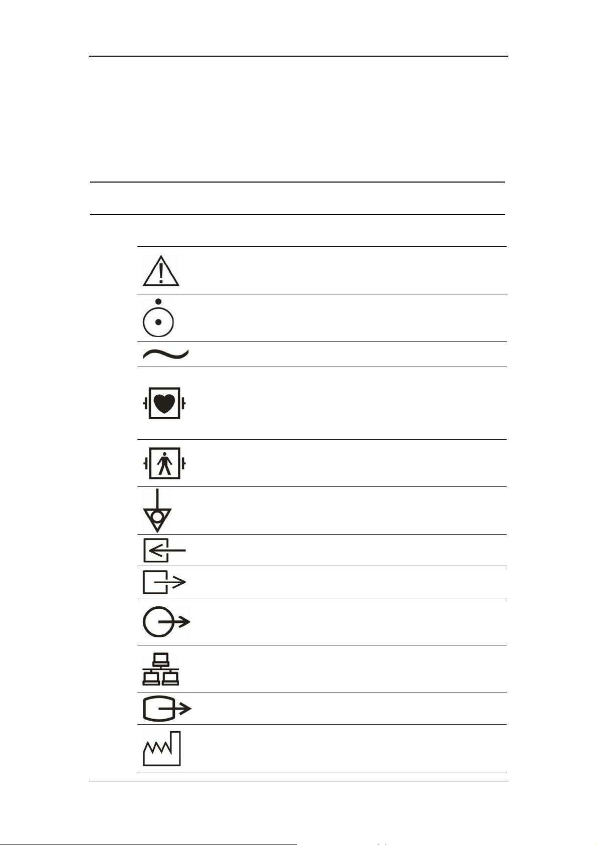
1.2 Equipment Symbols
NOTE
z Some symbols may not appear on all equipment.
Attention: Consult accompanying documents (this manual).
Power ON/OFF
Alternating current (AC)
Type CF applied part. The unit displaying this symbol contains
an F-type isolated (floating) patient part providing a high
degree of protection against shock, and is suitable for use
during defibrillation.
TYPE BF applied part. Defibrillator-proof protection against
electrical shock.
Equipotentiality
Gas inlet
Gas outlet
Auxiliary output
Network connector
VGA connector
Manufacture date
1-6
Safety
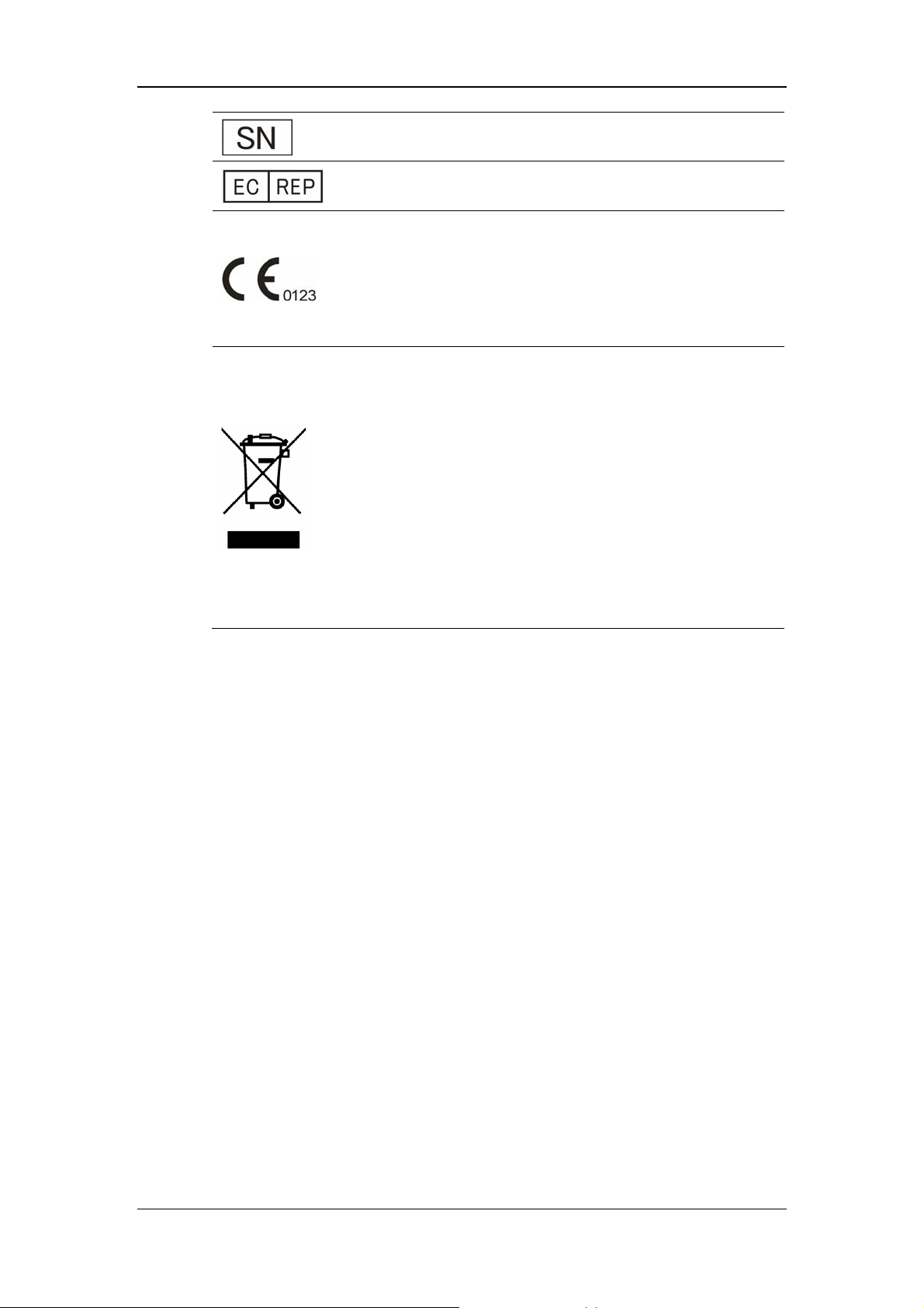
Serial number
European community representative
This mark means that this device is fully in conformance with
the Council Directive Concerning Medical Devices 93/42/EEC.
The number adjacent to the CE marking (0123) is the number
of the EU-notified body that certified meeting the requirements
of Annex II of the Directive.
The following definition of the WEEE label applies to EU
member states only.
This symbol indicates that this product should not be treated as
household waste. By ensuring that this product is disposed of
correctly, you will help prevent bringing potential negative
consequences to the environment and human health. For more
detailed information with regard to returning and recycling this
product, please consult the distributor from whom you
purchased it.
* For system products, this label may be attached to the main
unit only.
1-7

1.3 CE Marking
The patient monitor bears CE mark indicating its conformity with the provision of
Council Directive 93/42/EEC concerning medical devices, and fulfills the essential
requirement of Annex I of this directive.
The patient monitor is in radio-interference protection class A in accordance with
EN55011.
The product complies with the requirement of standard EN60601-1-2
“Electromagnetic Compatibility – Medical Electrical Equipment”.
Safety
1.4 Reference Literature
1. Medical Device Directive 93/42/EEC
2. EN60601-1+A1+A2 or IEC60601-1+A1+A2, Medical Electrical Equipment,
Part 1: General Requirements for Safety
3. EN60601-1-1 or IEC60601-1-1, Medical Electrical Equipment- Part 1-1:
General Requirements for Safety - Collateral Standard: Safety Requirements
for Medical Electrical Systems
4. IEC60601-1-4, Medical Electrical Equipment- Part 1-4: General Requirements
for Safety - Collateral Standard: Programmable Electrical Medical Systems
5. IEC60601-2-49 Medical Electrical Equipment-Part 2-49: Particular
Requirements for the Safety of Multifunction Patient Monitoring Equipment
1-8

2 The Basics
2.1 Monitor Description .................................................................................... 2-2
2.1.1 Intended Use.................................................................................... 2-2
2.1.2 Contraindications ............................................................................ 2-3
2.1.3 Components..................................................................................... 2-3
2.1.4 Functions......................................................................................... 2-3
2.2 External Appearance ................................................................................... 2-5
2.2.1 Front Panel ...................................................................................... 2-5
2.2.2 Side Panel........................................................................................ 2-6
2.2.3 Rear Panel ....................................................................................... 2-8
2.3 Control Panel............................................................................................. 2-10
2.4 Display ...................................................................................................... 2-12
2.5 Batteries .................................................................................................... 2-15
2.5.1 Battery Maintenance ..................................................................... 2-16
2.5.2 Battery Recycling.......................................................................... 2-17
2-1

The Basics
2.1 Monitor Description
This monitor integrates the functions of parameter measurement, waveform
monitoring, freezing, and recording, etc. Its color TFT liquid crystal display is able
to show patient parameters and waveforms clearly. The monitor also features
compact size, lightweight, easy-to-carry handle and built-in battery, which make it
portable, especially in hospital transport. The compact control panel and control
knob, and the easy-to-use menu system enable you to freeze, record, or perform
other operations conveniently. Besides, this monitor can be connected with the
central monitoring system whereby a monitoring network will be formed.
2.1.1 Intended Use
The intended use of this monitor is to monitor a fixed set of parameters (see 2.1.4
Functions) for single adult, pediatric and neonatal patient, to display patient data
and waveforms, to store patient data in a trend database, and to generate alarms and
recordings.
This monitor is to be used in but not restricted to medical institutions such as ICU,
CCU, cardiopathy ICU, operating room, emergency room and postoperative
observation ward etc. This monitor may also be used during hospital transport or
ambulance. This monitor is not intended for helicopter transport or home use.
WARNING
z This Monitor is to be operated by clinical physicians or appropriate
medical staffs under the direction of physicians. The operator of the
monitor must be well trained. Any operation by unauthorized or
non-trained personnel is forbidden.
z The physiological waveforms and parameters and the alarm information
displayed by the monitor are only for the reference of physicians, but
cannot be used directly to determine the clinical treatment.
2-2

2.1.2 Contraindications
None.
2.1.3 Components
This monitor consists of parameter measuring modules, blood pressure cuff, ECG,
IBP and CO cables, SpO
sensors, CO2 and AG measuring components. Some of the
2
components are optional and may not apply to your patient monitor.
2.1.4 Functions
The Basics
This monitor is capable of monitoring the following parameters.
ECG
Heart rate (HR)
2 channels of ECG waveforms
Arrhythmia and ST segment analysis (optional)
Pace analysis (PACE)
RESP
Respiration rate (RR)
Respiration waveform
SpO
Oxygen saturation (SpO
2
)
2
Pulse rate (PR)
SpO
plethysmogram
2
NIBP
Systolic pressure (NS), diastolic pressure (ND), mean pressure (NM)
TEMP
Temperature of channel 1 (T1), temperature of channel 2 (T2),
and temperature differential between two channels (TD)
IBP
CO
2 channels of IBP waveforms
Systolic (SYS), diastolic (DIA), and mean (MEAN) pressure.
Temperature of blood (TB)
Cardiac output (CO)
2-3

The Basics
CO
End-tidal carbon dioxide (EtCO
2
)
2
Fractional inspiratory carbon dioxide (FiCO2)
Air-way Respiration Rate (AwRR)
AG
Fraction of inspired carbon dioxide, nitrous oxide, oxygen or anesthetic
gas (FiCO
oxide or oxygen (EtCO
, FiN2O, FiO2, FiAA), and End-tidal carbon dioxide, nitrous
2
, EtN2O, EtO2, EtAA)
2
AA refers to one of the following anesthetic agents:
HAL (Halothame)
ISO (Isoflurane)
ENF (Enflurane)
SEV (Sevoflurane)
DES (esflurane)
Airway respiration rate (AwRR)
Minimum alveolar concentration (MAC)
4 channels of AG waveforms (CO
, N2O, O2 and AA)
2
This monitor has additional functions including visual & audible alarms, freezing,
data storage and output, recall, recording and drug calculation etc. Please refer to the
following corresponding chapters for details of each specific function.
2-4
The Basics
2.2 External Appearance
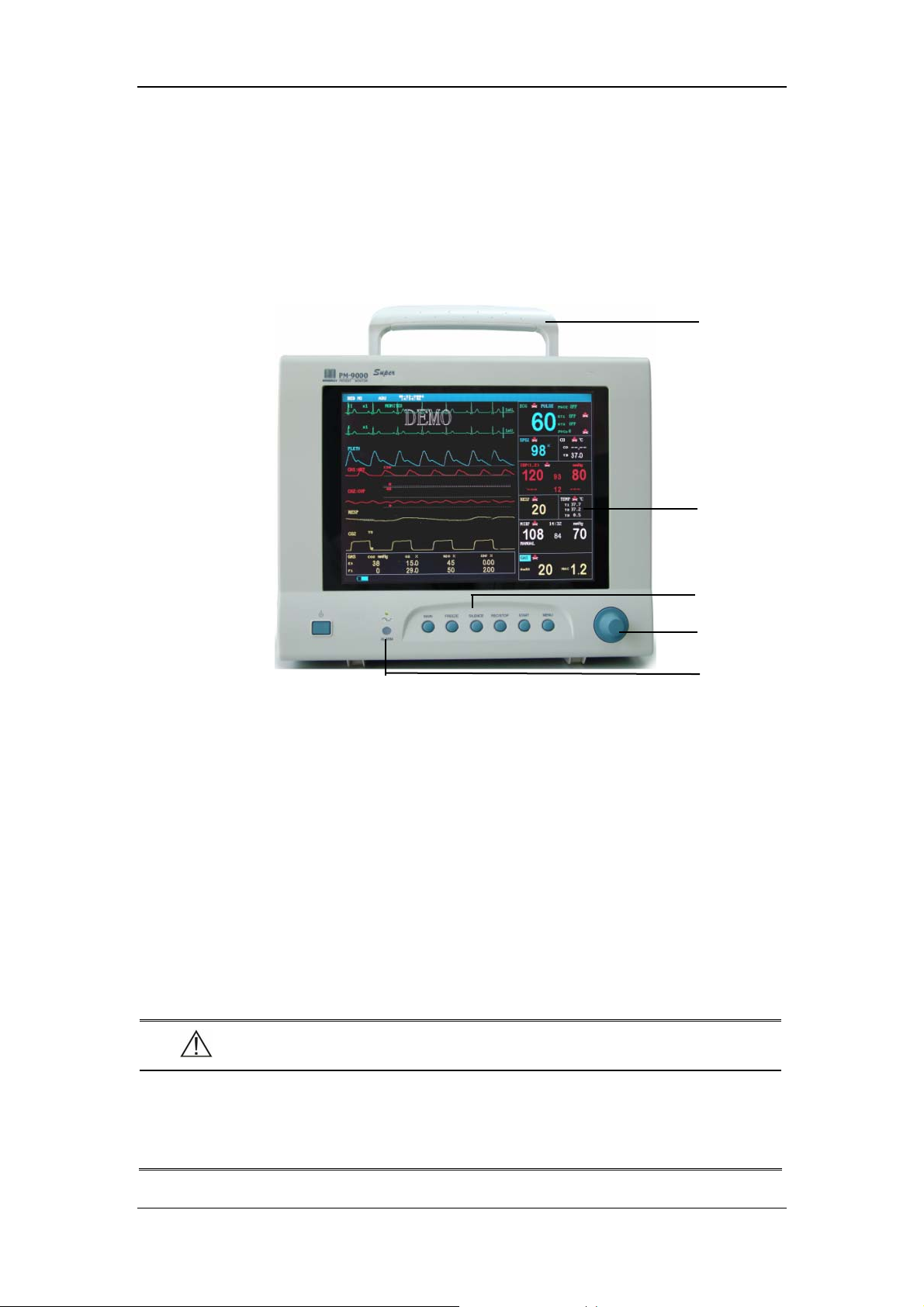
2.2.1 Front Panel
Handle
Display
Control panel
Control knob
Figure 2-1 Front Panel
This monitor is designed to comply with the requirements of relative international
safety standards (IEC60601-1, EN60601-2-27 and EN60601-2-30) for medical
electrical equipment. This monitor has floating inputs and is protected against the
effects of defibrillation and electrosurgery. When proper electrodes are used and
applied according to the manufacturer instructions, the screen display will recover
within 10 seconds after defibrillation.
The alarm indicator of this monitor complies with the requirement of EN60825-1
A11 Class 1 for LED. The LED indicator varies its flash color and frequency to
indicate different alarm levels. For details, please refer to the section of 6.2.1 Visual
Alarms.
Alarm indicator
WARNING
z Move or lift the monitor by the handle only. Do not use the patient cable
or the power cord to move or lift the monitor. It might cause the monitor
to fall, which might damage the monitor or injure the patient.
2-5
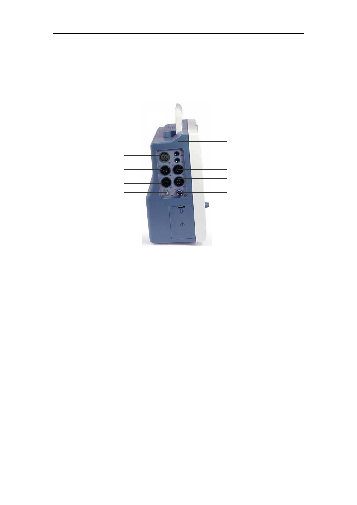
2.2.2 Side Panel
On the left side of the monitor, you can find the following connectors and the battery
compartment.
The Basics
2
1
3
4 5
6
7
8 9
10
Figure 2-2 Left Side Panel
1. CO
: CO2 sensor connector (Welch Allyn CO2 module)
2
2. T1: Temperature probe connector (channel 1)
3. T2: Temperature probe connector (channel 2)
4. IBP1: IBP transducer connector (channel 1)
5. IBP2: IBP transducer connector (channel 2)
6. ECG: ECG cable connector
7. CO: CO cable connector
8. NIBP: NIBP cuff hose connector
9. SpO
: SpO2 sensor connector
2
10. Battery door
2-6

The Basics
On the right side of the monitor, you can find the connector for Oridion or Mindray
CO
module or AG module. The recorder is located at the bottom of the right side.
2
2
1
3
4
(1) (2)
Figure 2-3 Right Side Panel
1. CO
2. Water trap connector (Mindray CO
: CO2 sensor connector (Oridion CO2 module)
2
or AG module)
2
3. Exhaust outlet
4. Recorder
NOTE
z Some modules are optional. Their connectors may not be available on
your patient monitor.
z Your monitor can be equipped with Oridion, Welch Allyn or Mindray CO
module. As shown in Figure 2-2 and Figure 2-3, they are located in
different position and have different appearance. For one monitor, only
one CO
module can be equipped.
2
2
z If your monitor is equipped with Mindray CO
equipped with AG module, vice versa.
2-7
module, then it can’t be
2

2.2.3 Rear Panel
The Basics
1
3
4
6
1. Fan Vent
2. Speaker holes
7 8
2
5
9
Figure 2-4 Rear Panel
3. Mounting holes for support bracket.
4. Network Connector: Standard RJ45 connector.
Through network connector, this monitor can be connected with the central
monitoring system, another monitor, or a PC. It enables the functions of viewbed
monitoring, data output and on-line software upgrading.
5. Fuse: Standard T3.0A
6. VGA Monitor Connector
A standard color VGA monitor can be connected to the patient monitor through this
connector.
2-8

The Basics
7. Equipotential grounding connector
8. Auxiliary Output Port: A standard BNC connector.
It is the common interface of analog output signals, nurse call output signals or
defibrillator synchronization signals. You can manually select the function of this
port in the USER MAINTAIN menu, please refer to 4.7 Maintenance for details.
9. AC Power Input Connector
A three-wire power cord can be connected to this receptacle to provide AC power
supply to the patient monitor.
To know details about the connections of the connectors, please refer to 3.1
Installation.
WARNING
z Accessory equipments connected to this patient monitor must be
certified according to the respective IEC standards (e.g. IEC 60950 for
information technology equipment and IEC 60601-1 for medical
electrical equipment). Furthermore all configurations shall comply with
the valid version of the system standard IEC 60601-1-1. Any person who
connects additional equipment to the signal input or signal output is
responsible to ensure the system complies with the requirements of the
valid version of the system standard IEC 60601-1-1. If in doubt, contact
our company or customer service.
2-9

2.3 Control Panel
The control panel as shown below is located at the bottom on the front panel. On the
control panel are the following keys and indicator.
The Basics
1 2 3 4 5 6 7 8 9
Figure 2-5 Control Panel
1. Power switch
This key turns the monitor ON and OFF. To turn OFF the monitor, please press this
key and hold for more than 2 seconds.
2. AC power indicator
ON: AC power is applied to the monitor.
OFF: AC power is not applied to the monitor.
3. MAIN
Press this key to exit the menu currently displayed, and return to the main screen.
4. FREEZE
This key is pressed to freeze and unfreeze waveforms. See 7 Freezing Waveforms
for more information.
5. SILENCE
You can press this key to pause alarms, silence the monitor or clear alarms. You can
also switch between different alarm statuses through this key. See 6.3.5 Status
Switchover for more information.
6. RECORD
Press this key to start or stop recording. See 8 Recording for more information.
7. NIBP
Press this key to start or stop the non-invasive blood pressure measurement. See 13
2-10

The Basics
NIBP Monitoring for more information.
8. MENU
Press this key to display the SYSTEM MENU, as shown in Figure 4-1.
9. Control Knob
The main operator control is the control knob. The control knob rotates in either
direction to highlight parameter labels and menu options. After highlighting the
desired selection, press the control knob to execute an operation, make a selection,
view a new menu or a small drop-down list. This procedure is referred to as “select ”
through out the manual. Remember rotate to highlight, and then press to select.
2-11

2.4 Display
This monitor has a color TFT LCD display of high resolution. It is able to display
patient parameters and waveforms clearly. The following is the standard interface
when the monitor is operating normally.
1 2 4
The Basics
3
5
6
8 9
Figure 2-6 Main Screen
1. Patient information area
It displays patient bed number and patient type. If no patient is admitted, it displays
“NO PATIENT ADMITTED”. If the patient’s information is incomplete,
corresponding symbols
2. System time
will be displayed.
7
The system time of the monitor is displayed in two lines. The time format can be set
in the TIME SETUP menu. For details, see 4.4.3 Time Setup.
3. Technical alarms area
Technical alarm messages or prompt information are displayed in this area. In case
of multiple messages, they will be displayed alternately. This area shows the patient
2-12

The Basics
name and sex when no message is to be displayed.
4. Sound icon
Alarms Paused ; System Silenced; Alarms Silenced. No icon is
displayed under normal status. For more information, see 6.3 Alarm Statuses.
5. Physiological alarms area
Physiological alarm messages are displayed in this area. In case of multiple
messages, they will be displayed alternately.
6. Waveforms area
For the maximum configuration, at most seven waveforms can be displayed in the
waveforms area, including two ECG waveforms, one SpO
waveforms, one CO
waveform and one RESP waveform. In HALF-SCREEN
2
plethysmogram, two IBP
2
MULTI-LEADS display mode, a maximum of ten waveforms can be displayed,
among which six are ECG waveforms. You may select the waveforms to be
displayed and adjust the display positions. For details, see 4.4.8 Trace Setup.
7. Parameter windows
ECG label
SPO2 label
IBP label
NIBP label
label
CO
2
RESP label
Heartbeat indicator
Alarms Disabled icon
CO label
TEMP label
Figure 2-7 Parameter Windows
The parameter windows are located on the right of the waveform area, and are
divided by white lines. Each window is identified by a parameter label on the upper
2-13

The Basics
left.
You may select a parameter label to open the setup menu of this parameter. Each of
the parameter is described in more detail in the following chapters. If you select to
turn OFF the alarm of a parameter in its corresponding setup menu, an Alarms
Disabled icon will be displayed aside the parameter label. For more information, see
6.3.1 Alarms Disabled.
8. Prompt information area
The battery symbol in this area displays the status of the battery. For more
information, please refer to 2.5 Batteries.
Upon turning ON the monitor, prompt information, for example “NIBP alarm
disabled”, will cover the battery symbol.
9. STANDBY label
You may select this label to enter the standby mode. For more information, please
refer to 5.6 Standby Mode.
2-14

2.5 Batteries
This monitor is designed to operate run battery power when during transport or
whenever the power supply is interrupted. The battery is charged automatically
when the monitor is connected to AC power, no matter the monitor is powered on or
not.
The battery symbol displayed on the main screen tells the status of the battery.
The Basics
The capacity of the internal battery is limited. When the battery capacity is too low,
a high level alarm is triggered and the “Battery two low” message is given in the
technical alarms area. At this moment, the AC power shall be applied to the monitor.
For details about installation of the battery, refer to the section 3.1.5.2 Installing the
Battery.
The battery is installed in the battery slot.
The solid part indicates its capacity.
No battery is installed in the battery slot.
NOTE
z Remove the battery before transport, or if the monitor is not likely to be
used for an extended period of time.
WARNING
z Keep the battery out of the reach of children.
z Use only the battery specified by the manufacturer.
2-15

The Basics
2.5.1 Battery Maintenance
2.5.1.1 Conditioning a Battery
A battery should be conditioned before it is used for the first time. A battery
conditioning cycle is one uninterrupted charge of the battery, followed by an
uninterrupted discharge of the battery. Batteries should be conditioned regularly to
maintain their useful life. Condition a battery once when it is used or stored for two
months, or when its run time becomes noticeably shorter.
To condition a battery, follow this procedure:
1. Disconnect the monitor from the patient and stop all monitoring or measuring.
2. Insert the battery in need of conditioning in the battery slot of the monitor, and
leave the other slot empty if your monitor has two slots.
3. Apply AC power to the monitor and allow the battery to charge uninterrupted
for 10 hours.
4. Remove AC power and allow the monitor to run from the battery until it shuts
off.
5. Apply AC power again to the monitor and allow the battery to charge
uninterrupted for 10 hours.
6. This battery is now conditioned and the monitor can be returned to service.
2.5.1.2 Checking a Battery
The performance of a rechargeable battery may deteriorate over time. To check the
performance of a battery, follow this procedure:
1. Disconnect the monitor from the patient and stop all monitoring or measuring.
2. Apply AC power to the monitor and allow the battery to charge uninterrupted
for 10 hours.
3. Remove AC power and allow the monitor to run from the battery until it shuts
off.
4. The operating time of battery reflects its performance directly.
If your monitor has two battery slots, you can check two batteries at the same time.
Please replace the battery or contact with the maintenance personnel if its operating
time is significantly lower than the specified time.
2-16

The Basics
NOTE
z Life expectancy of a battery depends on how frequent and how long it is
used. For a properly maintained and stored lead-acid or lithium ion
battery, its life expectancy is about 2 or 3 years respectively. For more
aggressive use models, life expectancy can be less. We recommend
replacing lead acid batteries every 2 years and lithium ion batteries
every 3 years.
z The battery might be damaged or malfunctioned if its operating time is
too short after being fully charged. The operating time depends on the
configuration and operation. For example, measuring NIBP more
frequently will also shorten the operating time.
2.5.2 Battery Recycling
When a battery has visual signs of damage, or no longer holds a charge, it should be
replaced. Remove the old battery from the monitor and recycle it properly. To
dispose of the batteries, follow local laws for proper disposal.
WARNING
z Do not disassemble batteries, or dispose of them in fire, or cause them
to short circuit. They may ignite, explode, leak or heat up, causing
personal injury.
2-17

FOR YOUR NOTES
The Basics
2-18

3 Installation and Maintenance
3.1 Installation................................................................................................... 3-2
3.1.1 Unpacking and Checking ................................................................ 3-2
3.1.2 Environmental Requirements.......................................................... 3-3
3.1.3 Power Source Requirements ........................................................... 3-3
3.1.4 Bracket Mounting............................................................................ 3-3
3.1.5 Installation Method ......................................................................... 3-4
3.1.6 Powering on the Monitor................................................................. 3-8
3.1.7 Powering off the Monitor................................................................ 3-8
3.2 Maintenance ................................................................................................ 3-9
3.2.1 Inspection ........................................................................................ 3-9
3.2.2 Cleaning ........................................................................................ 3-10
3.2.3 Disinfection ....................................................................................3-11
3-1

Installation and Maintenance
3.1 Installation
WARNING
z The installation of the monitor must be carried out by personnel
authorized by Mindray. The software copyright of the monitor is solely
owned by our company. Any action to change, copy or exchange the
software copyright by any organization or person is regarded as
copyright infringement and is not allowed.
3.1.1 Unpacking and Checking
Before unpacking, examine the packing case carefully for signs of damage. If any
damage is detected, contact the carrier or our company.
If the packing case is intact, open the package and remove the instrument and
accessories carefully. Check all materials against the packing list and check for any
mechanical damage. Contact our Customer Service Department for in case of any
problem.
NOTE
z Please save the packing case and packaging material for future
transport and storage.
WARNING
z Be sure to keep the packaging materials from children’s reach.
z Disposal of the packaging materials shall comply with your local
requirements.
z The equipment might be contaminated in storage, transport or when
used. Verify the package and the single use accessories are intact. In
case of any damage, do not apply it to patients.
3-2

Installation and Maintenance
3.1.2 Environmental Requirements
The operating environment of the monitor must meet the requirements specified in
the section A.2 Environmental Specifications of Appendix A Product
Specifications.
The environment where this monitor is to be used should be free from noise,
vibration, dust, and corrosive or explosive and inflammable substances. For a
cabinet mounted installation, allow sufficient room at the front and the rear of the
cabinet for operation, maintenance and servicing. Besides, allow at least 2 inches
clearance around the instrument for proper air circulation.
Condensation can form when the monitor is moved from one location to another,
and being exposed to differences in humidity or temperature. Make sure that during
operation the instrument is free from condensation.
3.1.3 Power Source Requirements
The power applied to the monitor must meet the requirements specified in the
section A.3 Power Source Specifications of Appendix A Product Specifications.
WARNING
z Make sure that the operating environment and the power applied to the
patient monitor complies the specified requirements. Otherwise its
performance might not meet the specifications claimed in Appendix A
Product Specifications, and unexpected results, such as damages to the
patient monitor, may be incurred.
z The monitor shall be powered according to the requirement for the
system power voltage. Otherwise, serious damage might be caused to
the system.
3.1.4 Bracket Mounting
For details, please refer to the corresponding instructions for use of bracket
mounting.
3-3

Installation and Maintenance
3.1.5 Installation Method
WARNING
z Accessory equipments connected to this patient monitor must be
certified according to the respective IEC standards (e.g. IEC 60950 for
information technology equipment and IEC 60601-1 for medical
electrical equipment). Furthermore all configurations shall comply with
the valid version of the system standard IEC 60601-1-1. Any person who
connects additional equipment to the signal input or signal output is
responsible to ensure the system complies with the requirements of the
valid version of the system standard IEC 60601-1-1. If in doubt, contact
our company or customer service.
z If the monitor is connected to another electrical instrument and the
instrument specifications cannot tell whether the instrument
combination is hazardous (e.g. due to summation of leakage currents),
you should consult Mindray or experts in the field to ensure the required
safety of all instruments concerned.
NOTE
z The following operations are not all required. User-customized
installation by authorized personnel is provided.
3.1.5.1 Connecting to AC Power Supply
1. Use the original three-wire AC power cord.
2. Connect the power cord to the receptacle for AC power cord on the rear panel
of the monitor.
3. Connect the other end of the power cord to a compatible 3-prong hospital grade
AC power outlet.
The 3-prong power outlet must be ground. If it is doubted, contact related personnel
of the hospital.
3-4

Installation and Maintenance
WARNING
z Do not use three-wire to two-wire adapter with this instrument.
z To avoid unexpected power interruption, do no use power outlet with a
wall-mounted switch control.
3.1.5.2 Installing the Battery
If the monitor is to be powered by the internal battery, install the battery following
the steps as below:
1. Slide the battery door toward the rear of the monitor to open it.
2. Move the battery catch above to one side using one finger.
3. Insert a battery into the battery slot.
4. Move the battery catch to another side, and then insert the other one in the same
way, if your monitor is equipped with two batteries.
5. Release the battery catch, and it will fix the battery.
6. Close the battery door.
WARNING
z Make sure the battery door is securely latched. Falling batteries could
seriously or fatally injure a patient.
3.1.5.3 Equipotential Grounding
When other equipments are used together with the monitor, a grounding cable
should be used to connect the equipotential grounding connectors of the monitor and
of other equipments. This helps to reduce the potential differences between different
pieces of equipment, and ensure the safety of the operator and patient.
WARNING
z If the grounding system is in doubt, the monitor must be supplied from
its internal battery.
3-5

Installation and Maintenance
3.1.5.4 Connecting Patient Sensors and Probes
Connect the necessary patient sensors or probes to the monitor. For details, see the
chapters for specific parameter monitoring in the following pages, or corresponding
instructions for sensors and probes.
3.1.5.5 Connecting the Network Cable
The network connector of the monitor is a standard RJ45 connector. It connects the
monitor with the central monitoring system, or with a PC for online upgrading or
data output. It can also connect with another patient monitor for viewbed
monitoring.
1. Connect one end of the network cable with the network connector of the
monitor.
2. Connect the other end of the network cable with the hub or switch of the central
monitoring system, or with the network connector of a PC, or with the network
connector of another patient monitor.
NOTE
z Different network cable may be used for different connections. Please
consult our customer service personnel for details.
z The system upgrading through the network connector is to be executed
by Mindray authorized personnel only.
3.1.5.6 Auxiliary Output Port
The auxiliary output port can be used to generate analog signals, nurse call signals
or defibrillator synchronization signals.
Analog output signals can be generated when the monitor is connected to an
oscilloscope or a pen recorder.
If the monitor is connected with the Nurse Call System of a hospital through a
special nurse call cable, the monitor can generate nurse call signals when
alarms occur.
If the monitor is connected with a defibrillation equipment, the monitor can
generate defibrillator synchronization signals to the defibrillation equipment.
3-6

Installation and Maintenance
To generate different signals, you must first select the AUX OUTPUT to
corresponding options. For details, please refer to 4.7 Maintenance.
NOTE
z For detailed connection methods of different uses, please consult the
specialist in your hospital, or our Customer Service.
z The nurse call cable has two non-polarized conducers at the output end.
The installation should be performed by Mindray servicing engineers or
engineers of the hospital according to the specific nurse call system of
the hospital.
WARNING
z Before defibrillating the patient, the user should ensure the defibrillator
and the monitor have been tested as a system and the two devices can
work together safely and effectively.
3.1.5.7 Connecting to VGA Monitor
This monitor can be connected with a standard color VGA monitor. The VGA
monitor will display the patient waveforms and parameters measured by the patient
monitor. To connect the patient monitor with the VGA monitor, follow the steps as
below.
1. Power off the patient monitor.
2. Connect the signal cable of the VGA monitor to the VGA connector on the rear
panel of the patient monitor.
3. Power on the VGA monitor and then the patient monitor.
NOTE
z The VGA monitor should be installed at a distance of more than 1.5 m
from the patient.
3-7

Installation and Maintenance
3.1.6 Powering on the Monitor
After installing the monitor, please follow the procedures described below to power
on the monitor:
1. Before using the monitor, please carry out corresponding safety inspection as
given in 3.2.1 Inspection.
2. Press the Power Switch on the control panel. A beep will be heard and, at the
same time, the alarm indicator will flash once in yellow and then red.
3. The system begins self-testing and the product model will be displayed on the
screen.
4. Several seconds later, the system finishes the self-test and displays the main
screen.
5. The system will initiate every module, and display “XX alarm disabled!”
information in the lower left part of the screen. “XX” represents the name of
every module, such as NIBP, RESP etc.
6. At this time, you can operate the monitor using the control panel. “XX alarm
disabled!” information will disappear a few seconds later.
When the monitor is plugged into AC power and is turned OFF or not turn ON, the
monitor only provides the function of battery charging.
NOTE
z During initialization process, alarms of every module detected by the
system are useless, and thereby are disabled.
3.1.7 Powering off the Monitor
To power off the monitor, please follow the procedures below:
1. Confirm the patient monitoring is to be finished.
2. Disconnect the cables and sensors between the monitor and the patient.
3. Confirm whether to store or clear the patient monitoring data.
4. Press the Power switch for more than 2 seconds, and the monitor will be
powered off.
3-8

Installation and Maintenance
3.2 Maintenance
WARNING
z Failure on the part of the responsible hospital or institution employing
the use of the monitoring equipment to implement a satisfactory
maintenance schedule may cause undue equipment failure and possible
health hazard.
z The safety inspection or maintenance, which requires opening the
monitor housing, must be performed by trained and authorize personnel
only. Otherwise, equipment failure and possible health hazard may be
caused.
3.2.1 Inspection
Make sure the qualified service personnel have implemented a complete inspection
before putting the monitor into operation, after monitor servicing or system
upgrading, or after the monitor has been used for 6-12 consecutive months. This is
to ensure the normal operation of the system.
Follow these guidelines when inspecting the equipment:
The environment and the power supply meet the specified requirements.
Inspect the keys, control knob, connectors and accessories for damage.
Inspect the power cords for fraying or other damage and check the insulation.
The grounding cables are correctly connected.
Only specified accessories like electrodes, sensors and probes are applied.
The monitor clock is correct.
The audible and visual alarms functions normally.
The recorder functions normally and the recorder paper meets the requirement.
The defibrillator synchronization function must be verified according to your
hospital regulations, and be checked by a qualified technician once every 3 months.
In case of any damage or exception, do not use the monitor. Contact the technician
in your hospital or our Customer Service immediately.
3-9

Installation and Maintenance
3.2.2 Cleaning
WARNING
z Be sure to shut down the system and disconnect all power cords from
the outlet before cleaning the equipment.
Your equipment should be cleaned on a regular basis. If there is heavy pollution or
lots of dust and sand in your place, the equipment should be cleaned more frequently.
Before cleaning the equipment, consult your hospital’s regulations for cleaning and
disinfecting equipment.
The exterior surfaces of the equipment may be cleaned with a clean and soft cloth,
sponge or cotton ball, dampened with a non-erosive cleaning solution. Drying off
excess cleaning solution before cleaning the equipment is recommended. Following
are examples of cleaning solutions:
Diluted soap water
Diluted ammonia water
Diluted sodium hyoichlo (bleaching agent)
Diluted formaldehyde (35 to 37%)
Hydrogen peroxide (3%)
Ethanol (70%), or Isopropanol (70%)
To avoid damage to the equipment, follow these rules:
ALWAYS dilute the solutions according to the manufacturer’s suggestions.
ALWAYS wipe off all the cleaning solution with a dry cloth after cleaning.
NEVER submerge the equipment into water or any cleaning solution, or pour
or spray water or any cleaning solution on the equipment.
NEVER permit fluids run into the casing, switches, connectors, or any
ventilation openings in the equipment.
NEVER use abrasive, erosive cleaners, or cleaners containing acetone.
Failure to follow these rules may erode or fray the casing, or blur lettering on the
labels, or cause equipment failures.
For cleaning information of accessories, please refer to the chapters for specific
patient parameters and the instructions for use of the accessories.
3-10

Installation and Maintenance
3.2.3 Disinfection
Disinfection may cause damage to the equipment. We recommend the disinfection is
contained in the hospital’s servicing schedule only when necessary. The equipment
should be cleaned prior to disinfection.
Recommended disinfection material: Alcohol based (Ethanol 70%, Isopropanol
70%), and aldehyde based.
WARNING
z Disinfection may cause damage to the equipment; therefore, when
preparing to disinfect the equipment, consult your hospital’s infection
controllers or professionals.
z The cleaning solutions above can only be used for general cleaning. If
you use them to control infections, we shall assume no responsible for
the effectiveness.
NOTE
z ALWAYS dilute the solutions according to the manufacturer’s
suggestions and adopt lower concentration if possible.
z NEVER submerge the equipment into water or any solution, or pour
water or any solution on the equipment;
z ALWAYS wipe off all the excess liquids on the equipment surface and
accessory surface with a dry cloth;
z Never use EtO and formaldehyde to disinfect.
z Never permit high-pressure and high-temperature disinfection of the
equipment and accessories.
3-11

FOR YOUR NOTES
Installation and Maintenance
3-12

4 System Menu
4.1 Overview..................................................................................................... 4-2
4.2 Patient Setup................................................................................................ 4-4
4.2.1 Admit Patient .................................................................................. 4-5
4.2.2 Quick Admit Patient ........................................................................ 4-7
4.2.3 Modify Patient................................................................................. 4-7
4.2.4 Clear Patient Data............................................................................ 4-8
4.2.5 Discharge Patient............................................................................. 4-8
4.3 Default Setup............................................................................................... 4-9
4.4 System Setup............................................................................................. 4-10
4.4.1 Face Select .....................................................................................4-11
4.4.2 Alarm Setup ...................................................................................4-11
4.4.3 Time Setup .................................................................................... 4-13
4.4.4 Recorder Setup .............................................................................. 4-14
4.4.5 Data Output ................................................................................... 4-16
4.4.6 Analog Output............................................................................... 4-17
4.4.7 Module Setup ................................................................................ 4-18
4.4.8 Trace Setup.................................................................................... 4-19
4.4.9 Mark Event.................................................................................... 4-20
4.5 Selection Setup.......................................................................................... 4-21
4.6 Monitor Version ........................................................................................ 4-22
4.7 Maintenance .............................................................................................. 4-24
4.7.1 IP Address Setup ........................................................................... 4-27
4.7.2 Wireless Net Setup ........................................................................ 4-27
4.7.3 Self Definition of Color................................................................. 4-28
4.7.4 Nurse Call Setup ........................................................................... 4-29
4.7.5 CO
4.7.6 Monitor Status............................................................................... 4-31
4.8 DEMO Function........................................................................................ 4-32
User Maintain........................................................................ 4-31
2
4-1

4.1 Overview
To open a menu, perform any of the following four operations:
1. Press the MENU key on the control panel. The SYSTEM MENU appears.
2. Select the STANDBY label on the main screen. The CONFIRM TO
STANDBY menu appears.
3. Select a parameter label in a parameter window. A parameter setup menu
appears. E.g. Select the ECG label to open the ECG SETUP menu.
4. Press the FREEZE key on the control panel. The FROZEN menu appears.
You can set the settings of the monitor by opening the menus above. Most settings
could be saved after the monitor is turned off. Few settings, which could not be
saved, will be specified in the relevant sections.
This chapter only gives introduction to the system menu. Other menus will be
described in the following chapters. Press the MENU key on the control panel. The
SYSTEM MENU appears as shown below.
System Menu
1
2
3
4
Figure 4-1 System Menu
Most menus displayed by the monitor share the same structure. As shown above, a
menu is made up of four parts:
1. Menu title: Summarizes the content of the current menu.
2. Main display area: Displays options, keys or prompt information, etc. “>>”
means a submenu will pop up if the option is selected.
3. Online help: The help information changes with the highlighted selection.
4-2

System Menu
4. Exit key: Exits from the current menu.
Some menus do not have the EXIT key. Instead, a YES and a NO key or a
CONFIRM and a CANCEL key are provided. You can confirm the operations with
these keys.
The following introduces the submenus of the SYSTEM MENU.
PATIENT SETUP>>
DEFAULT>>
SYSTEM SETUP>>
SELECTION>>
VERSION>>
MAINTAIN>>
DEMO>>
Details about the TREND GRAPH>>, TREND TABLE>>, NIBP RECALL>> and
ALARM RECALL>> are given in 9 Recall. While the DRUG CALC is detailed in
10 Drug Calculation.
4-3

4.2 Patient Setup
Select PATIENT SETUP>> in SYSTEM MENU. The following menu appears.
System Menu
Figure 4-2 Patient Setup Menu
This menu displays the patient’s information, as well as four buttons located below.
If no patient is admitted, only the default settings of PAT TYPE and PACE are
displayed. The DISCHARGE PATIENT and MODIFY PATIENT buttons are
disabled.
If a patient is admitted, the DISCHARGE PATIENT button turns to be
DISCHARGE PATIENT.
4-4

4.2.1 Admit Patient
To admit a new patient, please follow this procedure:
1. Select ADMIT PATIENT in PATIENT SETUP menu.
2. Select YES in the pop-up CONFIRM TO CLEAR THE DATA menu. The
menu as shown below appears.
System Menu
Figure 4-3 Patient Information Setup
3. Enter the patient’s information details. If the patient’s information is entered
incompletely, corresponding symbols
monitor screen.
PAT NO Patient identification number;
DOCTOR Name of the doctor;
NAME Patient name;
SEX Patient gender: “F” for female; “M” for male;
PAT T YP E
PAC E
Patient type:
ADU, PED and NEO (short for adult, pediatric and neonate);
Turn ON or OFF the pace analysis function;
will appear in the upper left hand of the
ADMIT The time when the patient is admitted: year-month-day;
4-5

System Menu
BIRTH Patient date of birth: year-month-day;
HEIGHT Patient height (unit: cm or inch);
WEIGHT Patient weight (unit: kg or IB);
BLOOD
Patient blood type:
A, B, O, AB or N (N represents unknown)
NOTE
z If the PAT NO or NAME has not been input, “PATI. INFO. IMCMP” will be
displayed in the patient information area.
4. Select OK button, and the patient is admitted.
5. If the monitor is connected with the central monitoring system, you can
monitor the patient through the central monitoring system.
Setting Patient Information
To enter information in a field containing no mark, follow this procedure (take
DEPT. as an example):
1. Rotate the control knob and highlight the field after DEPT.
2. Press the control knob, and the cursor jumps to the soft keypad below.
3. Rotate the control knob and move the cursor to the desired letter, number or
space, and press the control knob to enter the character. Select DEL button to
delete the unwanted entered character.
4. Repeat step 3 until you finish the information entering.
5. Select OK on the soft keypad. The information setting finishes.
To enter information in a field containing the mark “
SEX as an example):
1. Rotate the control knob and highlight the field after SEX.
2. Press the control knob. A pop-up menu opens.
3. Rotate the control knob and select the desired option.
To set a feild containing the mark “
example):
”, follow this procedure (take BED NO as an
”, follow this procedure (take
1. Rotate the control knob and highlight the field after BED NO.
4-6

System Menu
2. Press the control knob.
3. Rotate the control knob and select the desired bed number. The bed number
increases or decreases by one as the control knob rotates.
4.2.2 Quick Admit Patient
1. Select QUICK ADMIT PATIENT in PATIENT SETUP menu.
2. Select YES in the pop-up CONFIRM TO CLEAR THE DATA menu.
3. The menu as shown in Figure 4-4 appears. You can set the PAT TYPE and
status of PACE.
Figure 4-4 Quick Admit Patient
4. Select OK button, and the patient is admitted.
5. If the monitor is connected with the central monitoring system, you can
monitor the patient throuth the central monitoring system.
4.2.3 Modify Patient
To modify the information of the patient being monitored, please follow this
procedure:
1. Select MODIFY PATIENT button in PATIENT SETUP menu.
2. The menu as shown in Figure 4-3 opens.
3. Modify the patient’s information as described above, and select OK button.
4. Prompt information will be displayed on the central monitoring system if the
monitor is connected with it.
4-7

4.2.4 Clear Patient Data
If no patient is admitted, data stored in the patient monitor should be cleared.
1. Click the CLEAR PATIENT DATA button in the PATIENT SETUP menu.
2. Select YES in the pop-up menu.
4.2.5 Discharge Patient
If a patient has been admitted, the patient should be discharged.
To discharge the patient being monitored, please follow this procedure:
1. Select DISCHARGE PATIENT button in PATIENT SETUP menu.
2. Select YES in the pop-up menu.
System Menu
3. Prompt information will be displayed on the central monitoring system if the
monitor is connected with it.
4-8

4.3 Default Setup
Select DEFAULT>> in SYSTEM MENU. The following menu appears.
System Menu
Figure 4-5 Default Setup
Restoring Factory Default Configuration
1. Rotate the control knob and select the desired configuration.
2. Select EXIT, and a CONFIRM DEFAULT CONFIG dialog box pops up.
3. Select YES to restore the monitor to the selected default configuration, or select
NO to cancel the operation.
Saving Current Configuration as User Default Configuration
You can also modify the configuration of the monitor and save the modified
configuration as the user-defined default configuration of the corresponding patient
type. When the monitor begins monitoring a new patient, you may to choose the
user-defined default configuration directly, loosing from performing the settings
again. However, the user-defined configuration must be appropriate and correct.
1. Verify the modified configuration is appropriate and correct.
2. Select the SAVE CURRENT AS USER CONFIG option.
3. Select YES in the popup dialog box to save current configuration as the
user-defined default configuration.
4. Select NO to cancel the operation.
4-9

4.4 System Setup
Select SYSTEM SETUP>> in SYSTEM MENU. The following menu appears.
System Menu
Figure 4-6 System Setup
SYSTEM SETUP menu contains the following submenus:
FACE SELECT>>
ALARM SETUP>>
TIME SETUP>>
RECORD>>
DATA OUTPUT>>
ANALOG>>
MODULE SETUP>>
TRACE SETUP>>
MARK EVENT>>
4-10
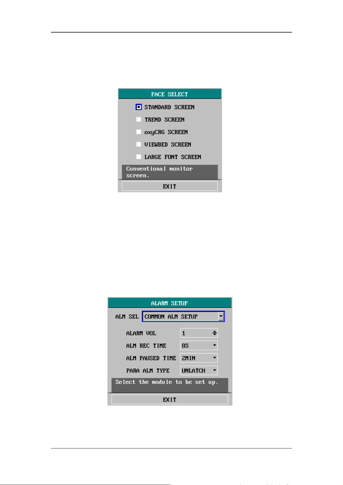
4.4.1 Face Select
Select FACE SELECT>> in SYSTEM SETUP menu. The following menu appears.
System Menu
In the FACE SELECT menu, options are available as shown above. For detailed
information, see 5 Face Selection.
4.4.2 Alarm Setup
Select ALARM SETUP>> in SYSTEM SETUP menu. The following menu appears.
Figure 4-7 Face Select
Figure 4-8 Alarm Setup
You can perform the following settings in the menu above:
4-11

System Menu
ALM SEL
ALARM VOL
ALM REC TIME
ALM PAUSED TIME Options: 1MIN, 2MIN and 3MIN.
PARA ALAM TYPE Options : LATCH and UNLATCH.
Detailed information about alarms is given in chapter 6 Alarms.
If a parameter alarm setup is selected from the drop-down list of ALM SEL, the
corresponding alarm setup items will be displayed in the ALARM SETUP menu.
When the ALARM VOL is set to 0, data will not be saved upon power failure. After
the monitor restarts, the ALARM VOL restores the default.
When the ALARM VOL is set to 0, it will restore its default if you silence or pause
alarms.
Alarm selection
Options: COMMON ALM SETUP, XX ALM SETUP;
(XX refers to HR, ST, PVCs, SPO2, NIBP, IBP (1,2),
CO2, RESP, TEMP, CO and AG).
Alarm volume
The volume can be set between 0 and 10. 0 means off
and 10 is the maximum volume.
Alarm recording time
Options: 8S,16S and 32S.
When an alarm occurs, the recorder records according
to the alarm recording time.
4-12

4.4.3 Time Setup
Select TIME SETUP>> in SYSTEM SETUP menu. The following menu appears.
System Menu
Figure 4-9 Time Setup
With the control knob, you can change the year, month, day, hour, minute and
second as well as select the displayed format of the time. YYYY, MM, and DD refer
to year, month and day respectively.
If the monitor is connected with the central monitoring system, the system time of
the monitor will be updated in accordance with the central monitoring system, and
the TIME SETUP option in SYSTEM SETUP menu will become disabled.
4-13

4.4.4 Recorder Setup
Select RECORD>> in SYSTEM SETUP menu. The following menu appears.
System Menu
Figure 4-10 Recorder Setup
REC WAVE1
In MULTI-LEADS DISPLAY mode or HALF-SCREEN MULTI-LEADS display
mode, the ECG3, ECG4, ECG5 and ECG6 options are also available. When OFF is
selected, waveform 1 will not be recorded.
REC WAVE2 Recorded waveform 2
Recorded waveform 2 has the same options as waveform 1, but the selected
waveform 2 cannot be identical to waveform 1. Otherwise, the system will
automatically change one of the waveforms to a different parameter.
Recorded waveform1
Options: ECG1, ECG2, SPO2, IBP1, IBP2, CO2, RESP,
N2O, O2, AA and OFF.
NOTE
z If a parameter is not displayed on the screen, this parameter will be
unavailable in the REC WAVE 1 and the REC WAVE 2 options.
4-14

System Menu
RT REC TIME
TIMING REC
TIME
Real-time recording time
Options: CONTINUAL and 8s.
Timing recording time
The interval between automatic recordings.
Options: OFF, 10MIN, 20MIN, 30MIN, 40MIN, 50MIN,
1HOUR, 2HOURS, 3HOURS and 4HOURS. The monitor
will start recording at the selected interval, record for 8s and
stop automatically.
NOTE
z TIMING REC TIME cannot be saved after the monitor is turned off. But it
can be saved as the user default configuration.
z RT REC TIME has priority over TIMING REC TIME.
REC RATE
Recording rate
Options: 25.0 and 50.0; unit: mm/s;
REC GRID
CLEAR REC
TASK
For details about recording operations, see chapter 8 Recording.
Recording grid
ON: You can select ON to print a grid on the recorder paper;
OFF: You can select OFF to print without grid on the
recorder paper.
Clear recording task
This key allows you to clear all current recording tasks.
4-15

4.4.5 Data Output
Select DATA OUTPUT>> in SYSTEM SETUP menu. The following menu appears.
System Menu
Figure 4-11 Data Output
Output Procedure
1. Disconnect all patient cables connected to the monitor.
2. Verify the monitor is connected to the PC and the PC is running the Patient
Information Recall System software.
3. Select from the five data source options: TREND, PARAM ALARM
(parameter alarm), DRUG CALC (drug calculation), NIBP and ARR ALARM
(arrhythmia alarm).
4. Select OUTPUT in the menu and the prompt ”CONNECTING…” is shown
aside. If you exit the DATA OUTPUT menu at this time, the prompt will be
displayed in prompt information area at the lower left corner of the screen.
5. If the connection is available, the data will be output to the PC. For more
information, please refer to the help information of the Patient Information
Recall System software.
NOTE
z If no data source is selected or the previous data output has not
finished, the OUTPUT option in the DATA OUTPUT menu will be inactive.
z During data output, the NEW PATIENT option in the PATIENT SETUP
menu is inactive.
4-16

4.4.6 Analog Output
Select ANALOG >> in SYSTEM SETUP menu. The following menu appears.
Figure 4-12 Analog Output
System Menu
You can perform the following settings in the menu above:
ANALOG OUT
ANALOG WAVE
Analog output
Options: ON and OFF.
When ON is selected, analog signals can be output from
the auxiliary output port on the rear panel of the monitor.
Options: ECG1, ECG2, IBP1 and IBP2;
In the MULTI-LEADS DISPLAY mode, the ECG3,
ECG4, ECG5 and ECG6 options are also available.
NOTE
z If DEFIB. SYN or NURSE CALL is selected from the AUX OUTPTU
options in the USER MAINTAIN menu, the ANALOG>> option in the
SYSTEM SETUP menu will be inactive, and the monitor will be unable to
output analog signals. For details, please refer to 4.7 Maintenance.
4-17

4.4.7 Module Setup
Select MODULE SETUP>> in SYSTEM SETUP menu. The following menu
appears.
System Menu
Figure 4-13 Module Setup
This menu allows you to enable or disable a parameter module to determine the
information displayed on the main screen. As shown in the figure above, “√”
indicates an enabled module. A module without the “√” mark is disabled and the
related waveform and parameter data disappear from the display.
4-18

4.4.8 Trace Setup
Select TRACE SETUP>> in SYSTEM SETUP menu. The following menu appears.
System Menu
Figure 4-14 Trace Setup
This menu allows you to select the parameter waveform(s) to be displayed. The
mark “√” indicates the parameter waveform will be displayed, and that without the
mark will not be displayed. The TRACE SETUP menu merely contains the
parameter modules enabled in the MODULE SETUP menu. Besides, in the
MULTI-LEADS DISPLAY mode or the HALF-SCREEN MULTI-LEADS display
mode, the ECG1 waveform and the ECG2 waveform are inactive.
In addition, the WAVE SEQUENCE >> option allows you choose in which sequence
the parameter waveforms are displayed from the upper to the lower.
Figure 4-15 Wave Sequence
4-19

4.4.9 Mark Event
Select MARK EVENT>> in SYSTEM SETUP menu. The following menu appears.
System Menu
Figure 4-16 Mark Event
This menu allows you to mark four different events, namely event A, B, C and D.
The ”@” symbol will appear in the frame of the even being selected. If you attempt
to unmark an event, press the control knob again on the marked selection.
The purpose of event marking is to define the records, such as dose taking,
injections or therapy, which have influence on patients and parameter monitoring. A
mark will be displayed on the trend graph/table indicating the time the mark was
initiated in relation to the event it represents.
4-20

4.5 Selection Setup
Select SELECTION>> in SYSTEM MENU. The following menu appears.
System Menu
Figure 4-17 Selection Setup
You can perform the following settings in this menu:
KEY VOL
HELP
SCAN TYPE
Key volume
The volume can be set between 0 and 10. 0 indicates the
volume is off and 10 indicates the maximum volume.
Online help
ON: Indicates the online help is enabled and the help
information will be displayed;
OFF: Indicates the online help function is disabled and the
help information will not be displayed.
Scan type
REFRESH: The waveform keeps stationary, with real-time
refreshing from the left to the right by a moving "erase bar";
SCROLL: The waveform moves from the right to the left
with time passing by.
ALM LIMIT
BRIGHTNESS
Alarm limit
ON: The alarm limits of parameters are displayed aside the
parameter value;
OFF: The alarm limits of parameters are not displayed aside.
The brightness can be set between 1 and 10. 1 indicates the
lowest brightness and 10 indicates the highest brightness.
4-21

4.6 Monitor Version
Select VERSION>> in SYSTEM MENU. The following menu appears.
System Menu
Figure 4-18 Version
You can see the software versions of the monitor. The DEVICE CONFIG LIST>>
option allows you to see the configuration of the monitor.
Figure 4-19 Device Configuration List
4-22

System Menu
The DEVICE VERSION LIST>> option allows you to see the following version
information.
Figure 4-20 Device Version List
4-23

4.7 Maintenance
Select MAINTAIN>> in SYSTEM MENU. The following menu appears.
System Menu
Figure 4-21 Enter Maintain Password
Enter USER KEY, then select CONFIRM button. The following menu appears.
Figure 4-22 User Maintain
You can perform the following settings:
4-24

System Menu
MONI NAME Monitor’s name.
DEPT. The department where the monitor is located.
BED NO The bed number where the monitor is located.
ALARM
SOUND OFF
The audible alarms will be turned ON when the monitor is restarted.
NET TYPE
LOCAL NET
NO
AUDIO MODE
ENABLE: the alarm volume can be set to 0;
DISABLE: the alarm volume cannot be set to 0..
Network type
Options: CMS and CMS+.
It indicates the bed number of a monitor in the monitoring
network. If the NET TYPE is CMS, the LOCAL NET NO can
be set between 1 and 64; if the NET TYPE is CMS+, it can’t
be set.
Audible alarm mode
Mode1: The monitor sounds at an interval of 8s when a high
priority alarm occurs, and at an interval of 24s when a
medium priority alarm occurs. The lead-off alarm is of the
low priority level.
Mode 2: The monitor sounds at an interval of 3s when a high
priority alarm occurs, and at an interval of 14s when a
medium priority alarm occurs. The lead-off alarm is of the
medium priority level.
LINE FREQ.
LANGUAGE Select the required language of the displayed texts.
AUX OUTPUT
1. ANALOG OUT (analog output)
If this option is selected, the auxiliary output port will be able to output analog
signals, and you can perform the settings in the ANALOG menu. For details,
see 4.4.6 Analog Output.
If this option is not selected, the analog output function will be disabled and the
ANALOG >> option in the SYSTEM SETUP menu will become inactive. In
this situation, you cannot set the information in the ANALOG menu.
Line frequency
Options: 50Hz and 60Hz;
If NOTCH is turned ON, the monitor filters the ECG signals
with the selected line frequency.
Three options are available:
4-25

System Menu
2. NURSE CALL
If this option is selected, the auxiliary output port will be able to output nurse
call signals, and you can perform the settings in the NURSE CALL SETUP
submenu of the USER MAINTAIN menu. For details, see 4.7.4 Nurse Call
Setup.
If not selected, the nurse call function will be disabled and the NURSE CALL
SETUP>> option in USER MAINTAIN will become inactive. In this situation,
you cannot set the information in the NURSE CALL SETUP submenu.
3. DEFIB. SYN (defibrillator synchronization signals)
If this option is selected, the auxiliary output port will be able to output
defibrillator synchronization signals. In this situation, you can turn on DEFIB
SYNC in the ECG SETUP menu to enable the defibrillator synchronization.
For details, see 1 1.3 ECG Setup Menu.
If not selected, the defibrillator synchronization function will be disabled and
the DEFIB SHNC option in the ECG SETUP menu will set to OFF (it will not
be user-adjustable).
LEAD
NAMING
Options: AHA and EURO;
For details, see 11.2.2 Electrode Placement.
WARNING
z Please be cautious when you use the ALARM SOUND OFF function.
NOTE
z If you set ALARM SOUND OFF to ENABLE when the ALARM VOL is 0,
the ALARM VOL will restore the default.
z The setting of the line frequency can neither be saved as the default user
configuration nor changed when the default factory configuration is
selected. Once set by a user, no operation except for manual adjustment
can change it. The setting keeps the same even when the monitor is
restarted.
4-26

4.7.1 IP Address Setup
When the monitor is connected with the central monitoring system, and the NET
TYPE is CMS+, you need to set the IP address of your monitor. Select IP
ADDRESS SETUP in USER MAINTAIN menu. The following menu appears. For
details, please contact with the technician responsible for the central monitoring
system in your hospital.
System Menu
Figure 4-23 IP Address Setup
4.7.2 Wireless Net Setup
This monitor can be configured with wireless network, which is connected to the
CMS (Central Monitoring System) in the wireless mode and constructs with the
CMS the monitoring network.
Note
z If the monitor is connected through the network connector, the use of
this connection is preferentialer than the wireless network.
z If the wireless network is configured, there will be a mark “√” in front of
“Wireless Net” in the DEVICE CONFIG LIST menu (See 4.6 Monitor
Version).
Select WIRELESS NET SETUP in USER MAINTAIN MENU. The following menu
appears. If the monitor connects with the central monitoring system through a
compact flash adapter, the ESS ID and CHANNEL NUMBER must be correctly set.
For details, please contact with the technician responsible for the central monitoring
system in your hospital.
4-27
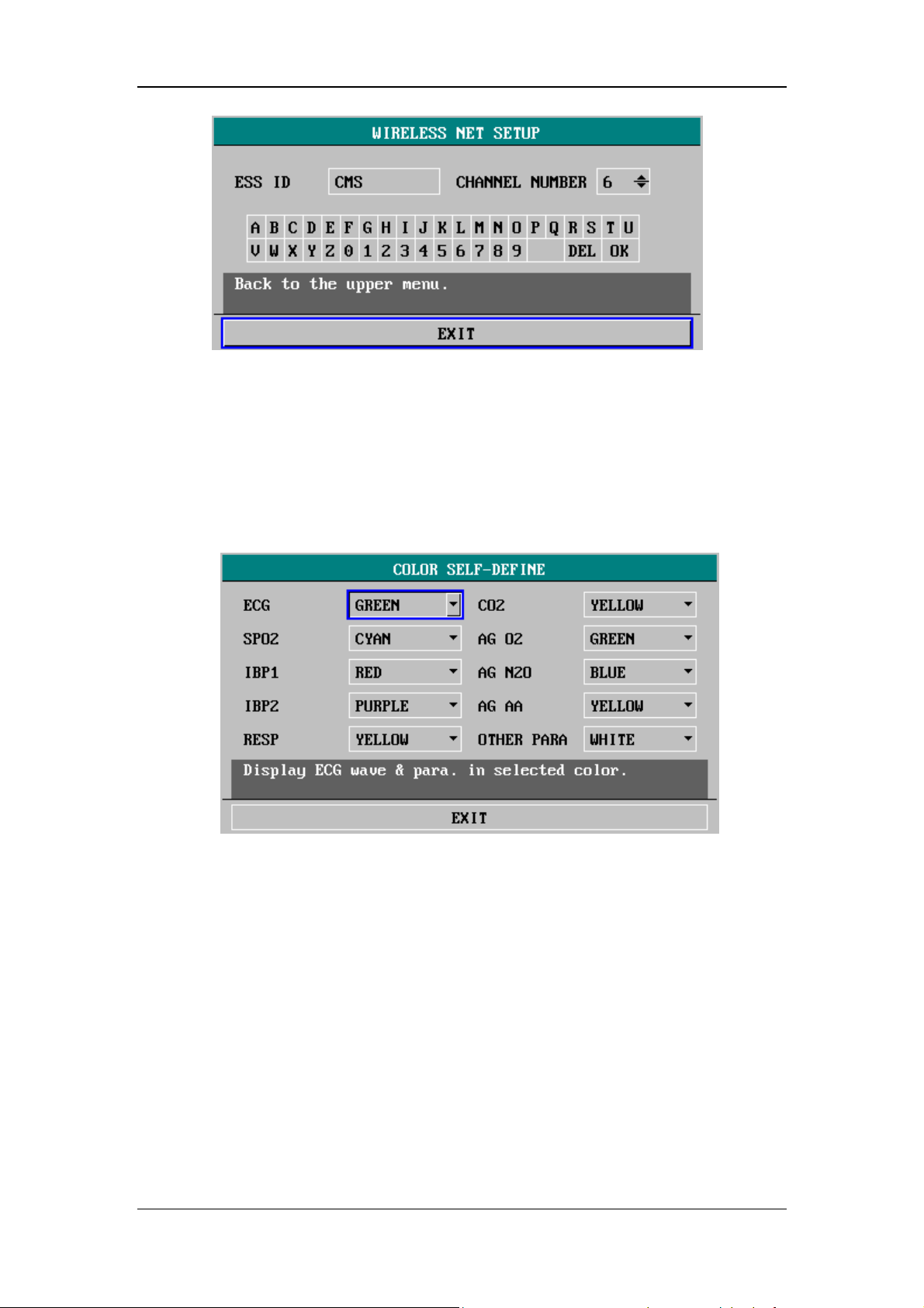
System Menu
Figure 4-24 Wireless Net Setup
4.7.3 Self Definition of Color
Select COLOR SELF-DEFINE >> in USER MAINTAIN menu. The following
menu appears.
Figure 4-25 Self-definition of color
This menu allows you to choose in which color the waveform(s) and parameter(s) of
a parameter module are to be displayed.
OTHER PARA refers to the parameters, NIBP and TEMP, which do not have
waveform.
CO2 refers to the parameters measured by CO
AG O2, AG N2O and AG AA refer to corresponding parameters measured by
AG module.
AA refers to the used anesthetic agent. If the anesthetic agent is available
before opening the COLOR SELF-DEFINE menu, the name of the anesthetic
agent will be displayed instead of AA.
4-28
module or AG module.
2

4.7.4 Nurse Call Setup
Select NURSE CALL SETUP >> in USER MAINTAIN menu. The following menu
appears.
System Menu
Figure 4-26 Nurse Call Setup
You can perform the following settings:
SIGNAL DURATION
Two options are available: PULSE, and CONTINUUM.
1. PULSE
When pulse is selected, a nurse call signal is a pulse signal lasting 1s. When multiple
alarms occur simultaneously, only one pulse signal will be output. If an alarm comes
out before the previous alarm is cleared, another pulse signal will be output.
2. CONTINUUM
When continuum is selected, the duration of a nurse call signal is the same with the
alarm, namely, from the time that the alarm occurs to the time it disappears.
SIGNAL TYPE
1. NORMAL OPEN: Select this option when the hospital’s call system is set to
NORMAL OPEN.
2. NORMAL CLOSE: Select this option when the hospital’s call system is set to
NORMAL CLOSE.
4-29

System Menu
ALM LEV
ALM TYPE
Trigger Conditions
A nurse call signal will be triggered only if all the following conditions are met:
1. The nurse call function is enabled.
2. An alarm of the preset alarm level and alarm type comes out.
3. The monitor is not in the Alarms Paused or the System Silenced status.
Alarm level
Options: HIGH, MED (medium) and LOW.
More than one option can be selected at one time.
Alarm type
Options: TECH. (technical) and PHYS. (physiological).
Both options can be selected at one time.
NOTE
z If no option in ALM LEV or ALM TYPE is selected, the nurse call signal
will not be triggered in whatever condition.
z The nurse call function can’t be used as the main alarm notice method.
Medical staff must combine the audible and visual alarms, the clinical
vital signs of the patient to determine the patient’s situation.
z In the Alarms Paused or the System Silenced status, the nurse call
function of the monitor will be disabled automatically.
4-30

4.7.5 CO2 User Maintain
Selecting CO2 USER MAINTAIN >> in USER MAINTAIN menu opens the CO2
USER MAINTAIN menu. The options contained in this menu are relative with the
CO
module that you monitor is equipped with. For details, please refer to 17.2.4
2
CO2 User Maintain Menu and 17.3.4 CO2 User Maintain Menu.
4.7.6 Monitor Status
Select STATUS >> in ENTER MAINTAIN PASSWORD menu. The following
menu appears.
System Menu
UP-DOWN
REC
Figure 4-27 Monitor Status
This menu can display a maximum of ten status messages. In
case of more than ten, you can select UP-DOWN to learn
other status messages.
Recording
You can select the REC option to record the status message
displayed.
4-31

4.8 DEMO Function
Select DEMO >> in SYSTEM MENU. The following menu appears.
Figure 4-28 Input Demo Key
System Menu
The monitor enters the demonstration mode when the correct password is input in
the menu above. The word DEMO will be displayed on the main screen. The
purpose of the demonstration display is to demonstrate the performance of the
monitor, and for training purposes.
WARNING
z In clinical applications, this function is forbidden because the DEMO
display can mislead the medical staff to treat the DEMO waveforms and
parameters as the actual data of the patient. This may result in serious
injury to the patient, or a delay of treatment or improper treatment.
4-32

5 Face Selection
5.1 Standard Screen........................................................................................... 5-2
5.2 Trend Screen ............................................................................................... 5-3
5.3 OxyCRG Screen.......................................................................................... 5-4
5.4 Viewbed Screen........................................................................................... 5-5
5.5 Large Font Screen ....................................................................................... 5-7
5.6 Standby Mode ............................................................................................. 5-8
5-1

Face Selection
5.1 Standard Screen
As described in 4.4.1 Face Select, you can open the FACE SELECT menu by
selecting FACE SELECT >> in SYSTEM SETUP menu.
Figure 5-1 Face Select
The standard screen is the default screen. If the current screen is not the standard
screen, you may enter the standard screen by selecting STANDARD SCREEN and
then selecting EXIT in FACE SELECT menu. For more information about the
standard screen, see 2.4 Display.
Figure 5-2 Standard Screen
5-2

5.2 Trend Screen
To enter the following screen, select TREND SCREEN in FACE SELECT menu and
then select EXIT.
Face Selection
Figure 5-3 Trend Screen
Trend graph
Trend graphs locate to the right of the corresponding waveform in the waveform
area, and display the trends of one parameter of each module. The parameter labels,
as well as their scales, are displayed to the left of the trend graph.
Trend length
The dynamic trend length, located below the trend graph, is 2 hours. On the trend
graph, the scale of the right end of the X-axis is 0 hour while the left end is -2 hour.
Selecting a trend parameter
If a module has multiple trend parameters, you can select one from the parameter
label options of the corresponding trend graph. The trend graph of the selected
parameter will be displayed. For example, in the ECG trend graph, you can select
either from the parameter lable options, HR, ST and PVCs.
5-3

5.3 OxyCRG Screen
To enter the following screen, select oxyCRG SCREEN in FACE SELECT menu
and then select EXIT.
Face Selection
3 2 1
Figure 5-4 OxyCRG Screen
Oxy CRG screen is located at the lower part of the waveform area, consisting of the
HR trend, the SpO
trend, and the RR (respiration rate) trend or the compressed
2
respiration waveform. Below the RR trend or the compressed respiration waveform
is the scale of the trend time. In addition, three labels are displayed beneath the time
scale (see 1, 2 and 3 in the figure above). The labels are detailed as below.
1. Trend length
This label allows you to select the time duration of the trend graphs displayed. You
can select either 1 MIN, 2 MIN or 4 MIN.
2. Compressed respiration waveform/RR trend
With this lable, you can select to display the compressed respiration waveform or
the RR trend beneath the SpO
trend.
2
3. Recording
You can select the REC label to print out the the trends or the waveform displayed in
the oxyCRG screen using the recorder.
5-4

5.4 Viewbed Screen
This monitor can view one parameter waveform and measured data from another
patient monitor (viewbed monitor) on the same monitoring network. To enter the
following screen, open FACE SELECT menu, select VIEWBED SCREEN, and then
select EXIT.
Face Selection
1
2
Figure 5-5 Viewbed Screen
The monitor you are viewing from is called “host monitor”. The monitor being
viewed is called “viewbed monitor”. The viewbed screen is always displayed at the
lower part of the host monitor’s waveform area. As shown in Figure 5-5, it consists
3
6
4
5
5-5

Face Selection
of the following parts.
1. Viewbed monitor label
The viewbed monitor lable allows you to select the viewbed monitor you want to
view. It displays the bed number and patient name of the viewbed monitor. If they
are not entered, the label displays blank. If the host monitor is not connected with
any other monitor on the same network, the label displays N/A.
2. Viewbed waveform label
The viewbed waveform label allows you to select a waveform of the viewbed
monitor. If the viewbed monitor does not dispaly any waveform, this label displays
N/A.
3. Viewbed alarm indicator
The viewbed alarm indicator in the viewbed screen is used to indicate the alarm
status of the viewbed monitor. Its color is identical with that of the viewbed monitor.
4. Viewbed parameter area
All parameter data of the viewbed monitor is displayed in this area.
5. Viewbed waveform area
The viewbed waveform area is located beneath the viewbed waveform label. It
displays the waveform selected through the viewbed waveform label. The scan type
(either refresh or scroll) and the sweep speed of the viewbed waveform follow the
host monitor. Besides, information relating to the viewbed waveform is shown
above the waveform.
6. Technical information area
On the right of the viewbed monitor label is the technical information area. It shows
the technical information about viewing of other patient, such as the prompt
information indicating failure in viewing other patient due to network problems.
Automatic Selection
When the viewbed screen is opened, the host monitor automatically selects a
viewbed monitor on the same network and a waveform of this monitor to view. In
case the monitor being viewed is disconnected, the host monitor automatically
closes the display of alarms, parameters and the waveform of the viewbed monitor.
However, the host monitor will not automatically select to view other monitor. You
must make the selection using the viewbed monitor label manually.
If a parameter module of the viewbed patient monitor is turned off or disassembled,
the corresponding waveform displayed on the host monitor disappears, and the
viewbed waveform area becomes blank. At this time, you can use the viewbed
waveform label to view other waveform.
NOTE
z When connecting by wireless network, viewbed function is disabled.
5-6

Face Selection
5.5 Large Font Screen
To enter the following screen, open FACE SELECT menu, select LARGE FONT
SCREEN, and then select EXIT.
Figure 5-6 Large Font Screen
As shown above, the HR, SpO2 and NIBP values (diastolic pressure, mean pressure
and systolic pressure) are displayed in large font. The ECG and SpO
displayed on the upper left of the screen. In case the ECG, SpO
module is turned off, the corresponding parameters and waveform disappear. If all
the three modules are closed, no waveform or parameter is displayed on the screen.
waveforms are
2
or NIBP parameter
2
NOTE
z When you open a menu in the large font screen mode, the monitor will
enter the standard screen automatically. When you exit the menu, the
monitor will return to the large font screen.
z If MULTI-LEADS DISPLAY is selected in the ECG SETUP menu, the
monitor cannot enter the large font screen.
5-7

5.6 Standby Mode
During patient transport or temporary departure of a patient, the monitor can be set
to STANDBY mode. In this mode, the monitor suspends the monitoring and
measurement on the patient and shields all alarm indications. Besides the WORK
MODE of CO
previous menu settings and patient information keep unchanged.
Entering the STANDBY mode
1. Disconnect all leads and sensors between the patient and the monitor.
2. Select the STANDBY label at the lower right corner of the main screen. A
dialog box pops up, and you can choose to enter the standby mode or not.
3. Select YES, and the monitor will enter the standby mode as shown below.
and AG module, which will also be changed to STANDBY, the
2
Face Selection
4. Select NO, and the monitor will return to the previous screen.
Figure 5-7 Standby Mode
Exiting the STANDBY mode
Press any key other than the power switch on the control panel or turn the control
knob in the STANDBY mode, and a dialog box will pop up. Select YES in the
dialog box, and you will exit the STANDBY mode and return to the previous screen.
5-8

6 Alarms
6.1 Overview..................................................................................................... 6-2
6.1.1 Alarm Categories............................................................................. 6-2
6.1.2 Alarm Levels................................................................................... 6-3
6.2 Alarm Modes............................................................................................... 6-4
6.2.1 Visual Alarms .................................................................................. 6-4
6.2.2 Audible alarms ................................................................................ 6-4
6.2.3 Alarm Messages .............................................................................. 6-5
6.2.4 Parameter Flashes............................................................................ 6-5
6.3 Alarm Statuses ............................................................................................ 6-6
6.3.1 Alarms Disabled.............................................................................. 6-6
6.3.2 Alarms Paused................................................................................. 6-7
6.3.3 System Silenced .............................................................................. 6-7
6.3.4 Alarms Silenced .............................................................................. 6-7
6.3.5 Status Switchover............................................................................ 6-8
6.4 Latching Alarms .......................................................................................... 6-9
6.5 Clearing Alarms ........................................................................................ 6-10
6.6 When an Alarm Occurs ..............................................................................6-11
6-1

6.1 Overview
The monitor gives audible or visual alarms to indicate the medical staff, when a vital
sign of the patient appears abnormal, or mechanical or electrical problems occur to
the monitor.
Upon turning on the monitor, a beep will be heard. At the same time, the alarm
indicator will flash once in yellow and red. This is used to verify the audible and
visual alarm function of the monitor. If no beep is heard, or the alarm indicator
doesn’t flash normally, please do not use the monitor, and contact our customer
service.
For details about alarm setup of this monitor, please refer to 4.4.2 A larm Setup.
Alarms
6.1.1 Alarm Categories
The alarms are divided into three categories: physiological alarms, technical alarms
and prompt information.
1. Physiological alarms
A physiological alarm either indicates that a monitored physiological parameter is
out of specified limits or indicates an abnormal patient condition. For example: HR
TOO LOW, ECG LOST or RESP ARTIFACT, etc. Physiological alarm messages are
displayed in the physiological alarms area of the main screen.
2. Technical alarms
Technical alarms are also referred to as system error messages. A technical alarm
indicates that the monitor or parts of the monitor is not capable of accurately
monitoring the patient’s condition due to improper operation or system failure. For
example: ECG INIT ERR or TEMP SELFTEST ERROR, etc. Technical alarm
messages are usually displayed in the technical alarms area of the main screen. But
the technical alarms related to NIBP are displayed in the lower part of the NIBP
parameter window.
3. Prompt information
Strictly speaking, prompt information cannot be counted in alarms. It is usually
information relating to the system, but not concerning vital signs of patients. For
6-2

Alarms
example, the monitor prompts ”NIBP alarm disabled ! ” at the time the monitor is
powered on. Besides, if a parameter module is turned on but the required leads or
sensor are not connected, the monitor will prompt accordingly, such as ”ECG LEAD
OFF” or ”SPO2 SENSOR OFF”, etc. Prompt information is usually displayed in the
technical alarms area. But the prompt information relating to NIBP is displayed in
the lower part of the NIBP paramter window.
NOTE
z To distinguish from the prompt information, the alarm message is
displayed with yellow or red background.
6.1.2 Alarm Levels
The alarms are divided into three priority levels: high level alarms, medium level
alarms and low level alarms.
1. High level alarms
The patient ‘s life is in danger and requires emergency treatment, or
Serious technical problem occurs to the monitor, such as error in ECG module
initialization.
2. Medium level alarms
Vital signs of the patient become abnormal, and patient requires immediate
treatment, or
Certain technical problem occurs to the monitor, such as error in temperature
calibration.
3. Low level alarms
Certain technical alarm occurs to the monitor, such as ECG lead off in
measurement.
The levels of all technical alarms and some physiological alarms are not
user-adjustable, because they have been fixed when the monitor is produced.
However, you can change the levels of some physiological alarms in the
corresponding parameter setup menus.
All physiological alarms, technical alarms and prompt information are given in
Appendix C Alarm Messages and Prompt Information.
6-3

6.2 Alarm Modes
When an alarm occurs, the monitor raise the user’s attention by the following
audible or visual indications.
Visual alarms
Audible alarms
Alarm messages
Parameter flashes
Besides, the visual alarms, audible alarms and alarm messages are given in different
ways to identify different alarm levels.
Alarms
6.2.1 Visual Alarms
The alarm indicator on the front panel of the monitor varies its flash color and
frequency to indicate different alarm levels.
High level alarm: red and quick flash;
Medium level alarm: yellow and slow flash;
Low level alarm: yellow light without flash.
6.2.2 Audible alarms
The monitor uses different alarm tones to indicate different alarm levels.
High level alarm: “DO-DO-DO--DO-DO---DO-DO-DO--DO-DO”.
Medium level alarm: “DO-DO-DO”.
Low level alarm: “DO”.
Different intervals correspond to different alarm levels: High level alarm phonates
once every 3 or 8 seconds. Medium level alarm phonates once every 14 or 24
seconds. Low level alarm phonates once every 24 seconds. For details, please refer
to 4.7 Maintenance.
6-4

Alarms
NOTE
z When multiple alarms of different levels occur simultaneously, the
monitor selects the alarm of the highest level and gives alarm tone
accordingly.
6.2.3 Alarm Messages
Alarm messages are given when alarms occur. The alarm messages are displayed in
the physiological alarms area or the technical alarms area in black. For physiological
alarms, asterisks are displayed before the alarm messages to identify the alarm level.
High level alarms: triple asterisks “***”
Medium level alarms: dual asterisks “**”
Low level alarms: single asterisk “*”
The monitor varies the background color of the technical and physiological alarm
messages to indicate the alarm level.
High level alarms: red background color
Medium level alarms: yellow background color
Low level alarms: yellow background color
NOTE
z Comparing with an alarm message, the background color of prompt
information is the same as that of the position where it appears.
z The NIBP technical alarm messages appear in the NIBP parameter
window. For high level alarms, the text color is red; for medium and low
level alarms, the text color is yellow. The background color is the same
as the parameter window.
6.2.4 Parameter Flashes
An alarm is triggered when a patient parameter exceeds the parameter limit. At the
same time, the measured parameter value in the parameter window flashes every
second. If the ALM LIMIT in the SELECTION menu is turned ON, the exceeded
upper or lower alarm limit also flashes every second.
6-5

6.3 Alarm Statuses
When an alarm occurs, normally the monitor gives indications in the modes
mentioned above as per the alarm level. If necessary, you can the set the monitor to
the following alarm statuses.
Alarms
Alarms Disabled
Alarms Paused
System Silenced
Alarms Silenced
6.3.1 Alarms Disabled
If the alarm switch of a parameter is turned off, the monitor does not generate alarms
even if the measured parameter value exceeds the alarm limit. This status is called
Alarms Disabled.
To disable the alarms of a parameter, you should open the setup menu of the
parameter. Take heart rate (HR) as an example.
1. Rotate the control knob and highlight the ECG parameter label.
2. Press the control knob. The ECG SETUP menu pops up.
3. Rotate the control knob and highlight the field on the right of HR ALM.
4. Press the control knob, and then select OFF from the pull-down list.
5. The HR alarms are disabled. The
ECG parameter label.
icon will be displayed on the right of the
NOTE
z When a new parameter module is installed or when a parameter module
is turned ON, all the parameter alarms and technical alarms related to
this module are disabled in the first 30-second operating time. The other
module alarms are not influenced.
6-6
 Loading...