


Mindray Datascope Passport V Service Manual
Service Manual

Service Manual

CapnoLine® is a U.S. registered trademark of Oridion Medical Ltd.
Copyright © Mindray DS USA, Inc., 2009. All rights reserved. Contents of this publication may not be reproduced in any
form without permission of Mindray DS USA, Inc.
DRYLINE
Durasensor
Edwards
FilterLine
LNCS
LNOP
Masimo SET
Max-Fast
miniMediCO
Microstream
Navigator
Nellcor
NIV Line
Oxiband
™
is a trademark of Artema Medical AB
®
is a U.S. registered trademark of Nellcor Puritan Bennett Inc.
®
is a U.S. registered trademark of Edwards Lifesciences Corp.
®
is a U.S. registered trademark of Oridion Medical Ltd.
®
is a U.S. registered trademark of Masimo Corp.
®
is a U.S. registered trademark of Masimo Corp.
®
is a U.S. registered trademark of Masimo Corp.
™
is a trademark of Nellcor Puritan Bennett Inc.
®
is a U.S. registered trademark of Oridion Medical Ltd.
2
®
is a U.S. registered trademark of Oridion Medical Ltd.
™
is a U.S. trademark of Mindray DS USA, Inc.
™
is a U.S. trademark of Nellcor Puritan Bennett Inc.
™
is a trademark of Oridion Medical Ltd.
®
is a U.S. registered trademark of Nellcor Puritan Bennett Inc.
™
OxiMax
Oxisensor
Passport V
Velcro
Viewstation OR
Windows
is a U.S. trademark of Nellcor Puritan Bennett Inc.
®
is a U.S. registered trademark of Nellcor Puritan Bennett Inc.
™
is a U.S. trademark of Mindray DS USA, Inc.
®
is a registered trademark of Velcro Industries B.V.
™
is a U.S. trademark of Mindray DS USA, Inc.
®
is a registered trademark of Microsoft Corp.
Passport V™ Service Manual 0070-10-0705

Tabl e o f Co nt en ts
Foreword....................................................................................................................................................... v
Warnings, Cautions, and Notes .......................................................................................................................v
Warnings ......................................................................................................................................................v
Cautions ........................................................................................................................................................v
Notes ............................................................................................................................................................vi
Theory of Operation ......................................................................................................... 1 - 1
Introduction.................................................................................................................................................... 1 - 1
System Connections ........................................................................................................................................1 - 2
Mounting the Patient Monitor ....................................................................................................................1 - 2
Connectors for Peripheral Devices .............................................................................................................1 - 2
Main Unit ......................................................................................................................................................1 - 3
Input System ........................................................................................................................................... 1 - 4
Output System.........................................................................................................................................1 - 4
Processing and Communications System..................................................................................................... 1 - 6
Power Management System ......................................................................................................................1 - 6
Equipment Interface System.......................................................................................................................1 - 8
Parameter modules ..................................................................................................................................1 - 10
Block Diagrams ................................................................................................................ 2 -1
Introduction.................................................................................................................................................... 2 - 1
Block Diagram................................................................................................................................................ 2 - 2
Repair Information ........................................................................................................... 3 - 1
Introduction.................................................................................................................................................... 3 - 1
Safety Precautions...........................................................................................................................................3 - 1
Troubleshooting Guidelines ..............................................................................................................................3 - 2
Special Tools Required ....................................................................................................................................3 - 2
Disassembly Instructions................................................................................................................................... 3 - 2
Removal of the Key Panel and Keys ...........................................................................................................3 - 3
Removal of the Front Housing Assembly .....................................................................................................3 - 4
Removal of the Main Board ......................................................................................................................3 - 5
Removal of the Inverter.............................................................................................................................3 - 6
Removal of the LCD Panel......................................................................................................................... 3 - 7
Removal of the Keyboard .........................................................................................................................3 - 8
Removal of the Alarm LED Board ...............................................................................................................3 - 9
Removal of the Encoder............................................................................................................................3 - 9
Removal of the Multi-parameter Board Assembly .........................................................................................3 - 10
Removal of the Parameter Front Panel Assembly .......................................................................................... 3 - 12
Removal of the Multi-parameter board........................................................................................................3 - 13
Removal of the CO
Removal of the Masimo SpO
Removal of the Nellcor SpO
Removal of the NIBP Assembly ..................................................................................................................3 - 15
Removal of the Recorder Assembly ............................................................................................................3 - 15
Removal of the Recorder Cover (if needed) ................................................................................................. 3 - 16
Removal of the Main Frame and Multi-parameter Board Assembly ................................................................. 3 - 16
Removal of the Speaker Assembly .............................................................................................................3 - 17
Removal of the Fan Assembly.................................................................................................................... 3 - 18
Removal of the CF Card Assembly.............................................................................................................3 - 19
Removal of the Power Board .....................................................................................................................3 - 19
Removal of the Li-ion Battery Interface Board Assembly................................................................................. 3 - 21
Removal of the Interface Board Assembly ...................................................................................................3 - 23
Removal of the Wireless AP ...................................................................................................................... 3 - 25
Nurse Call Cable............................................................................................................................................3 - 27
Module..................................................................................................................... 3 - 13
2
Module ....................................................................................................... 3 - 14
2
Module ........................................................................................................ 3 - 14
2
Passport V™ Service Manual 0070-10-0705 i

Tabl e o f Co nt ent s
P/N 8000-21-10361 ..............................................................................................................................3 - 27
Analog Output Cable ......................................................................................................................................3 - 27
P/N 6100-20-86360 ..............................................................................................................................3 - 27
Defib Synch Cable ..........................................................................................................................................3 - 28
P/N 6100-20-86361 ..............................................................................................................................3 - 28
Serial Port to Gas Module 3 Cable ...................................................................................................................3 - 29
P/N 0012-00-1276-XX ............................................................................................................................3 - 29
Null Modem Cable ......................................................................................................................................... 3 - 30
P/N 0012-00-1275-01............................................................................................................................3 - 30
Universal ECG Lead Wires .............................................................................................................................. 3 - 31
P/N 0012-00-1503-XX ............................................................................................................................3 - 31
ECG Cable, 3/5-lead (ESIS and Non ESIS)........................................................................................................ 3 - 32
P/N 0012-00-1745-XX ............................................................................................................................3 - 32
12-pin 3-lead Neo ECG Trunk Cable (IEC/AHA) ................................................................................................3 - 32
P/N 040-000072-00 ..............................................................................................................................3 - 32
IBP Cable....................................................................................................................................................... 3 - 33
P/N 040-000052-00 ..............................................................................................................................3 - 33
P/N 040-000053-00 ..............................................................................................................................3 - 33
P/N 040-000054-00 ..............................................................................................................................3 - 33
P/N 040-000096-00 ..............................................................................................................................3 - 34
Temperature Cable .........................................................................................................................................3 - 34
1.15.1 P/N 040-000055-00 ...................................................................................................................3 - 34
P/N 040-000056-00 ..............................................................................................................................3 - 34
P/N 040-000057-00 ..............................................................................................................................3 - 35
P/N 040-000058-00 ..............................................................................................................................3 - 35
P/N 040-000091-00 ..............................................................................................................................3 - 35
P/N 040-0000100-00 ............................................................................................................................3 - 36
P/N 040-000224-00 ..............................................................................................................................3 - 36
Troubleshooting Menus.................................................................................................................................... 3 - 37
ECG Troubleshooting ...............................................................................................................................3 - 37
NIBP Troubleshooting...............................................................................................................................3 - 39
Troubleshooting..............................................................................................................................3 - 40
SpO
2
Temperature Troubleshooting ....................................................................................................................3 - 42
Resp Troubleshooting ............................................................................................................................... 3 - 43
IBP Troubleshooting .................................................................................................................................3 - 44
Troubleshooting ...............................................................................................................................3 - 45
CO
2
Gas Module Troubleshooting ....................................................................................................................3 - 48
Trends Troubleshooting............................................................................................................................. 3 - 50
Printer/Recorder Troubleshooting .............................................................................................................. 3 - 50
Monitor/Display Troubleshooting ..............................................................................................................3 - 52
Remote View Troubleshooting ...................................................................................................................3 - 52
Installation Menu ............................................................................................................................................3 - 53
Installation Mode.....................................................................................................................................3 - 53
Advanced Installation Setup Menu.............................................................................................................3 - 56
Options Menu......................................................................................................................................... 3 - 57
Trend Storage ................................................................................................................................................ 3 - 57
Software Download ........................................................................................................................................3 - 58
Isometric Drawings and Parts List ..................................................................................... 4 - 1
Introduction.................................................................................................................................................... 4 - 1
Top Level Assembly .........................................................................................................................................4 - 2
Main Unit Assembly ........................................................................................................................................ 4 - 4
Front Housing Sub-assembly .............................................................................................................................4 - 5
ii 0070-10-0705 Passport V™ Service Manual

Tabl e o f Co nt en ts
Rear Housing Sub-assembly ............................................................................................................................. 4 - 6
Main Chassis Sub-assembly .............................................................................................................................4 - 7
Interface Connector PCB Assembly....................................................................................................................4 - 9
Parameter Sub-assembly ..................................................................................................................................4 - 10
Patient Connector Sub-assembly........................................................................................................................4 - 11
NIBP Module Assembly ...................................................................................................................................4 - 12
Microstream CO
DPM CO
Masimo SpO
Nellcor SpO
Module Assembly .................................................................................................................4 - 13
2
Module Assembly............................................................................................................................ 4 - 14
2
PCB Assembly........................................................................................................................... 4 - 15
2
Module Assembly .......................................................................................................................4 - 16
2
Calibration Procedure ....................................................................................................... 5 - 1
Introduction.................................................................................................................................................... 5 - 1
Warnings and Guidelines................................................................................................................................ 5 - 1
Test Equipment and Special Tools Required........................................................................................................ 5 - 2
Services......................................................................................................................................................... 5 - 2
ECG Channels Check ..............................................................................................................................5 - 3
NIBP Maintenance...................................................................................................................................5 - 4
NIBP Accuracy Test .........................................................................................................................5 - 4
NIBP Leakage Test ...........................................................................................................................5 - 5
NIBP Calibration ............................................................................................................................. 5 - 5
IBP Calibration........................................................................................................................................ 5 - 6
Calibration .....................................................................................................................................5 - 6
CO
2
Gas Calibration ......................................................................................................................................5 - 8
Monitor Log ............................................................................................................................................5 - 11
Verification ....................................................................................................................................................5 - 12
Initial Set-up............................................................................................................................................5 - 12
ECG ......................................................................................................................................................5 - 13
Initialization .................................................................................................................................... 5 - 13
Leads OFF ...................................................................................................................................... 5 - 13
Pacer Detect ................................................................................................................................... 5 - 13
Performance Test ............................................................................................................................. 5 - 14
IBP 1 and IBP 2 Verification ......................................................................................................................5 - 14
Temperature Verification........................................................................................................................... 5 - 14
Verification....................................................................................................................................5 - 14
SpO
2
NIBP Verification .....................................................................................................................................5 - 14
Battery Operation Verification................................................................................................................... 5 - 15
Operation Verification......................................................................................................................5 - 15
CO
2
Leakage Current Tests ..............................................................................................................................5 - 15
Preventative Maintenance................................................................................................. 6 - 1
User Preventative Maintenance Introduction .......................................................................................................6 - 1
Preventative Maintenance Schedule .................................................................................................................. 6 - 2
Mechanical / Physical / Visual Inspection - Annually ...................................................................................6 - 2
Visual test ...............................................................................................................................................6 - 2
Power on test ..........................................................................................................................................6 - 2
Perform NIBP Verification and Calibration – Annually ..................................................................................6 - 2
Perform CO
Perform IBP Verification and Calibration – Annually..................................................................................... 6 - 2
Perform ECG Verification – Annually..........................................................................................................6 - 2
Perform Verification and Gas Calibration – Annually ...................................................................................6 - 3
Temperature Perform Verification – Annually ...............................................................................................6 - 3
SpO
2
Electrical Safety Tests – Annually ...............................................................................................................6 - 3
Verification and Calibration -- Annually................................................................................... 6 - 2
2
Perform Verification – Annually ........................................................................................................6 - 3
Passport V™ Service Manual 0070-10-0705 iii

Tabl e o f Co nt ent s
Care and Cleaning of the Monitor .................................................................................................................... 6 - 4
Decontamination of the Monitor ................................................................................................................6 - 4
Care and Cleaning of SpO
Cleaning and Re-use of a Nellcor
Cleaning CO
Sensors, Adapters and Sampling Components ..............................................................................6 - 6
2
Sensors................................................................................................................. 6 - 5
2
®
Sensor.................................................................................................. 6 - 5
Sterilization and Cleaning of Cuffs....................................................................................................................6 - 7
Reusable Cuffs with Bladders ....................................................................................................................6 - 7
Reusable Bladderless Cuffs .......................................................................................................................6 - 8
Disposable Blood Pressure Cuffs................................................................................................................ 6 - 8
Care and Cleaning of Gas Module................................................................................................................... 6 - 9
Care and Cleaning of 3- and 5-lead ECG Cables and Leadwires .........................................................................6 - 10
Battery Replacement and Maintenance ..............................................................................................................6 - 11
Battery Replacement ................................................................................................................................6 - 11
Battery Maintenance ................................................................................................................................6 - 11
Recorder Maintenance ....................................................................................................................................6 - 12
Cleaning the Recorder Printhead ...............................................................................................................6 - 12
Recorder Paper Replacement ....................................................................................................................6 - 12
Care and Storage of Thermal Chart Paper.................................................................................................. 6 - 12
Warranty Statements....................................................................................................................................... 6 - 14
USA, Canada, Mexico, and Puerto Rico.....................................................................................................6 - 14
International (excluding North America) .....................................................................................................6 - 15
Phone Numbers and How To Get Help ......................................................................................................6 - 16
Manufacturer’s Responsibility ....................................................................................................................6 - 16
iv 0070-10-0705 Passport V™ Service Manual

Foreword Introduction
Foreword
The Passport V Service Manual is intended as a guide for technically qualified personnel
during repair and calibration procedures. This publication may have been updated to reflect
product design changes and/or manual improvements.
Warnings, Cautions, and Notes
Please read and adhere to all warnings, cautions, and notes listed here and in the
appropriate areas throughout this manual.
A WARNING is provided to alert the user to potential serious outcomes (death, injury, or
serious adverse events) to the patient or the user.
A CAUTION is provided to alert the user to use special care necessary for the safe and
effective use of the device. They may include actions to be taken to avoid effects on patients
or users that may not be potentially life threatening or result in serious injury, but about which
the user should be aware. Cautions are also provided to alert the user to adverse effects on
this device of use or misuse and the care necessary to avoid such effects.
A NOTE is provided when additional general information is applicable.
Warnings
WARNING: The Passport V operates on line voltages. Therefore, an
electric shock hazard may exist when the instrument covers
are removed. Repair and calibration procedures should only
be performed by qualified personnel who proceed with care
and follow proper servicing techniques. Warnings are given
in various chapters, as well as in other appropriate
locations.
WAR N I NG: In t e rnal El e c trical S hock Ha zard - This unit does not contain
any user-serviceable parts. Do not remove instrument
covers. Refer Servicing to qualified personnel.
WAR N I NG: Wh e n ever th e monito r is open e d for c a l ibratio n or rep a i r, a
risk (leakage) current safety check and a verification of
basic functions of all parameters should be performed
before the monitor is returned to Clinical use. See
“Verification” on page 5-12.
WAR N I NG: Do n ot clea n the mon i tor while it is powered on and/or
plugged in.
WAR N I NG: Pe r f o rm t h e d e contami n ation process with the unit powered
off and the power cord removed.
Cautions
CAUTION: Calibration is not to be performed while monitoring a
patient.
CAUTION: A functional tester cannot be used to assess the accuracy of
the pulse oximeter probe or a pulse oximeter monitor.
Passport V™ Service Manual 0070-10-0705 v

Introduction Notes
CAUTION: When cleaning the monitor, do not allow cleaning solutions
CAUTION: When cleaning sensors, do not use excessive amounts of
CAUTION: Some disinfectants may cause skin irritation. Please rinse
CAUTION: Using dark colored soaks may stain the cuffs. Test a single
CAUTION: When ironing or pressing the cuffs, be aware that the
CAUTION: Disposable cuffs can be cleaned using a mild soap solution
CAUTION: Do not clean the Gas Module while it is on and/or plugged
CAUTION: The internal sampling system of the Gas Module does not
into the vent openings.
liquid. Wipe the sensor surface with a soft cloth dampened
with cleaning solution. Do not attempt to sterilize.
cuff thoroughly with water to remove any residual
disinfectants.
cuff to ensure that no damage will occur.
®
Vel c ro
(162°C).
and dried with a clean cloth.
in.
need to be cleaned or sterilized. There is no reverse flow
back to the patient. If the internal sampling system is
suspected to be clogged or dirty, the module should be
serviced by an authorized service person only.
fasteners can melt at temperatures above 325°F
CAUTION: To avoid permanent damage, do not expose metal
components (e.g., pins, sockets, snaps) to disinfectants,
soaps, or chemicals.
CAUTION: Recharge batteries in the Passport V.
CAUTION: Remove the batteries if the Passport V is not likely to be
used for an extended period of time.
CAUTION: Never pull the recorder paper with force when a recording
is in process; it may cause damage to the recorder.
CAUTION: Do not leave the recorder door open unless reloading paper
or troubleshooting.
Notes
NOTE: Unauthorized servicing may void the remainder of the
warranty. Check with the factory or with a local authorized
representative to determine the warranty status of a
particular instrument.
vi 0070-10-0705 Passport V™ Service Manual
1.0
Theory of Operation
1.1 Introduction
This patient monitor is intended to be used for monitoring, displaying, reviewing, storing,
and transferring of multiple physiological parameters including: ECG, respiration (Resp),
temperature (Temp), SpO
blood pressure (IBP), End tidal CO
pediatric, and neonatal patients.
, pulse rate (PR), non-invasive blood pressure (NIBP), invasive
2
value (EtCO2) and anesthetic gas (AG) of single adult,
2
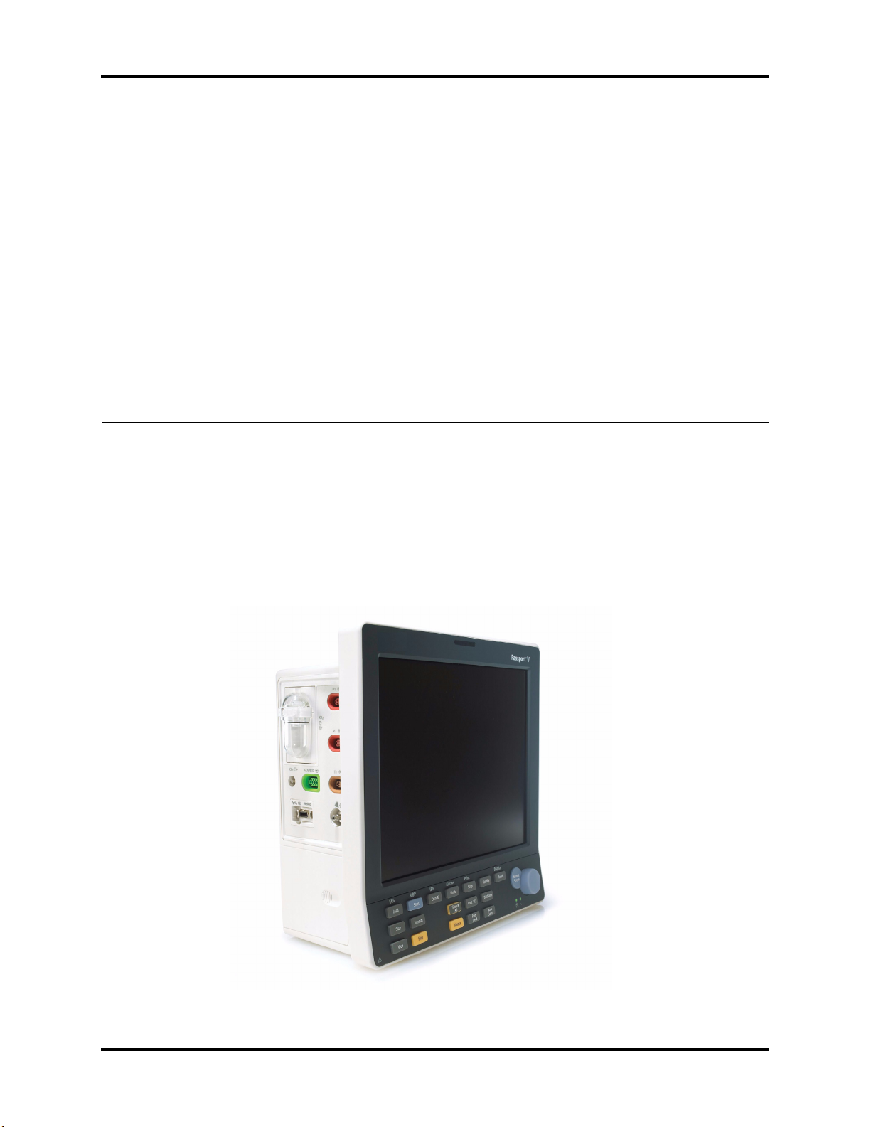
FIGURE 1-1 The Passport V Monitor
Passport V™ Service Manual 0070-10-0705 1 - 1
System Connections Theory of Operation
Additional Passport V features:
•Provides audible and visual alarm indications.
•Incorporates multiple input devices such as a keypad and knob.
•Enables program upgrade over the network.
1.2 System Connections
1.2.1 Mounting the Patient Monitor
The Passport V can be mounted on a wall mount bracket, a rolling stand, or a bedrail
hook, which can be ordered optionally. Each type of mounting solution is delivered with a
complete set of mounting hardware and instructions. Refer to the documentation delivered
with the mounting hardware for instructions on assembling mounts.
1.2.2 Connectors for Peripheral Devices
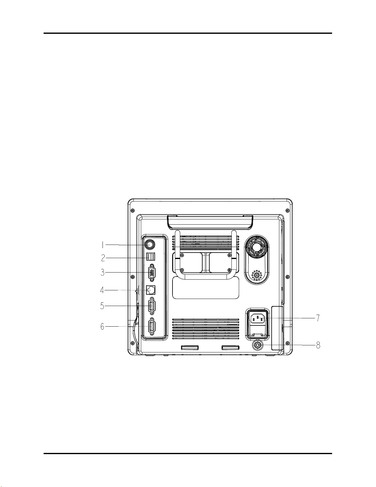
On the back of the Passport V are the connectors for peripheral devices.
FIGURE 1-2 Connectors for Peripheral Devices
1 - 2 0070-10-0705 Passport V™ Service Manual

Theory of Operation Main Unit
1. Auxiliary Output
A standard BNC connector, through which defibrillator synchronization signals, analog
output signals, and nurse call signals can be outputted, depending on how the monitor is
configured.
2. SB Connector
A connector for an external storage device.
3. VGA Connector
A connector for a standard SVGA color monitor.
4. Network Connector
An RJ45 connector, through which an Ethernet network or a PC can be connected.
5. RS232 serial port
A DB9 connector, used to connect a PC for data or a Gas Module 3, depending on how
the monitor is configured.
6. RS232 serial port
A DB9 connector, used to connect a PC for data or a Gas Module 3, depending on how
the monitor is configured.
7. AC Power Connector
A connector for an AC power source (100 to 240 VAC, 50/60Hz).
8. Equipotential lug
A connector for common ground with other equipment.
1.3 Main Unit
The Passport V consists of the following:
• Input system:
keypad, knob, and power switch.
• Output system:
LCD panel, alarm LED board, recorder, speaker, AC/battery status LEDs).
• Processing and communications system:
CPU board, Power management and interface board.
• Power management system:
battery, battery interface board, power board (AC/DC), Power management and
interface board.
• Equipment interface system:
power management and interface board, Ethernet-wireless adapter.
• Parameter modules:
multi-parameter board, CO
Additionally, the patient monitor can also connect a DPM SB storage device, a Gas
Module 3, or a PC for data transfer.
module, OEM SpO2 module, NIBP module.
2
Passport V™ Service Manual 0070-10-0705 1 - 3
Main Unit Theory of Operation
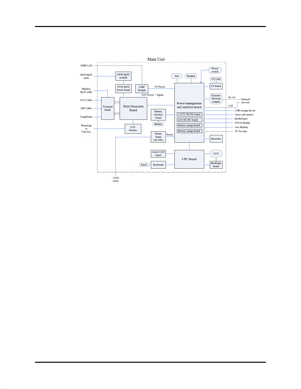
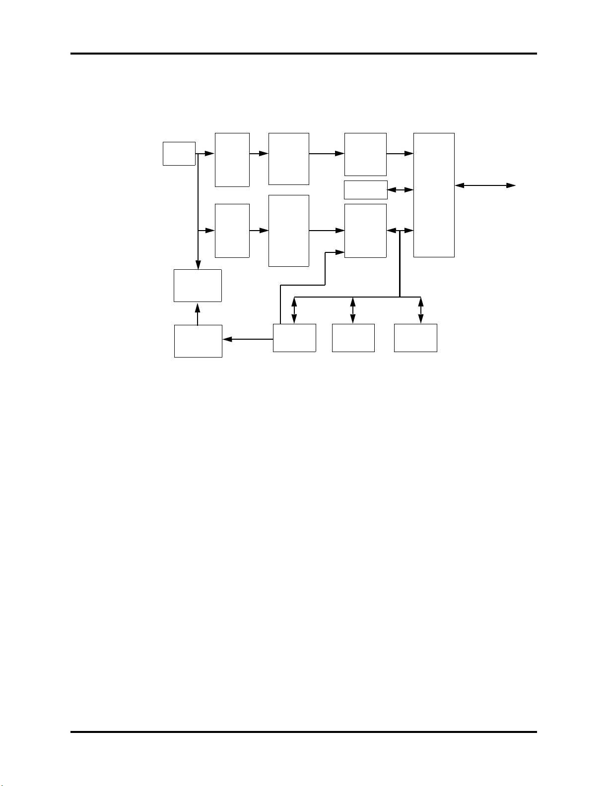
The following diagram illustrates the structure of the patient monitor.
FIGURE 1-3 Patient monitor structure
1.3.1 Input System
Keypad
The keypad, located at the lower part of the monitor’s front panel, contains 18 keys, AC
status LED and battery status LED, and also provides a connection for the knob to the CPU
board.
Knob
The knob can be pressed, or rotated either clockwise or counter-clockwise. It connects to the
keypad.
Power switch
The power switch, located at the right side of the monitor, is a single-throw rocker switch.
Pressing it will power the monitor on or off. The power switch’s status is detected by the
power management and interface board.
1.3.2 Output System
LCD Panel
The monitor uses an LCD panel with a resolution of 800x600, which runs power and gets
digital signals from the CPU board. The backlight is powered by the backlight board, which
is powered by the CPU board.
1 - 4 0070-10-0705 Passport V™ Service Manual
Theory of Operation Main Unit
MAIN BOARD
POWER
MODULE
CPU
DRIVE
CIRCUIT
RECORDER
KEY BOARD
FPC INTERFACE
THERMAL PRINT HEAD
MOTOR
CONTROL
POWER
SUPPLY
CONTROL
POWER
SUPPLY
INTERFACE
KEY & LED
INTERFACE
SIGNAL
INTERFACE
Alarm Lamp
The monitor has an alarm lamp on the front panel. The alarm LED board converts the electric
signals into visual signals and then sends the visual signals to the alarm lamp through a light
pipe. The alarm lamp illuminates either red or yellow, depending on how the alarm is
configured.
Recorder
The recorder receives data coming from the CPU board through a UART and then sends them
to the thermal print head for printing. The recorder has a hard key (starting/stopping
recordings) and a green LED on its front. It connects to the power management and interface
board.
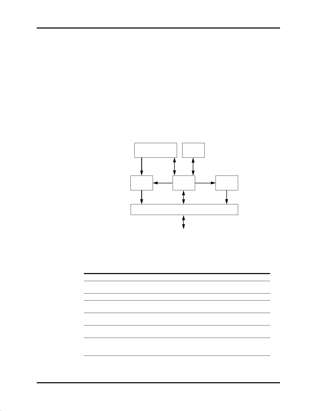
The following diagram shows its operating principle.
FIGURE 1-4 Operating principle
MODULE DESCRIPTION
Power supply interface Introduces a DC from the CPU board.
Power module Converts the input power into voltages that fit each module and
CPU Controls the communications between modules.
Signal interface Controls the communications between the CPU board and the
Drive circuit Receives control signals from the CPU and then forwards them to
Recorder key board Sends key commands to the CPU and receives commands from
FPC interface Sends the thermal print head information to the CPU and
Passport V™ Service Manual 0070-10-0705 1 - 5
then forwards them to each module.
recorder CPU.
the stepper motor.
the CPU to control the LED on the recorder.
receives commands from the CPU to control the thermal print
head.

Main Unit Theory of Operation
Speaker
The speaker provides sound for alarms, key strokes, heart beats, pulse, and so on. It is driven
directly by the CPU board.
AC and battery status LEDs
The AC status LED and the battery status LED, located at the keypad, are controlled by the
MCU on the power management and interface board. The driving signals come from the
power management and interface board and then go to the keypad via the CPU board.
1.3.3 Processing and Communications System
CPU board
The CPU board is the heart of the patient monitor. It implements a series of tasks including
input and output control, data storage and processing, display processing, system control,
communication management, print management, alarming, etc.
The CPU board has a CPU system comprising the CPU, FLASH, memory, real-time clock,
EEPROM, FPGA, etc. Among them, FPGA deals with audio, video, and interfacing signals.
Also, it provides interfaces to other boards, modules, and devices.
Connections and communications with other components are implemented via the CPU
board, which provides interfaces to:
•A built-in display
•The power management and interface board. Between this board and the CPU board,
the signals of USB+Network+UART+SVGA+I2C+Speaker+GPIO are communicated.
Among them, UART signals finally go to the parameter boards.
•The keypad. Between the keypad and the CPU board, there are two signal wires: one is
the UART signal wire and another is the AC power and battery status signal wire.
•The alarm LED board
Power management and interface board
The power management and interface board is a multi-functional board. It transmits UART
signals to several boards and modules (e.g., multi-parameter board, CO
SpO
module, NIBP module, recorder module, etc.).
2
1.3.4 Power Management System
Battery
The monitor uses two rechargeable lithium-ion batteries (11.1 V, 4400 mAh). The battery
compartment door is located at the left-bottom of the patient monitor. The battery power is
introduced to the power module via the battery interface board, and then processed and
distributed to each component by the power management and interface board.
module, OEM
2
Battery interface board
The battery interface board serves as an interface between the batteries and the power
management and interface board.
1 - 6 0070-10-0705 Passport V™ Service Manual
Theory of Operation Main Unit
DC source
11.1V
16.8V/11.1V
5V
DC/DC
3.3V
DC/DC
Recorder
5V
Wireless
Adapter
CF control
board
NIBP
CO2
modul e
CPUboard
digital circuit
Interfaceboard
digital circuit
LCD digital
circuit
3.3V
12V
DC/DC
Multi-
Parameter
board
OEM SpO2
module
Backlight
board
Alarm
indicator
Knob
Power
board
(AC/DC)
Battery
interface
board
16.8V
12V
Power management
and interface board
auto-select
Power board (AC/DC)
The power board (AC/DC) converts the input AC power to DC power (16.8V DC), which
then serves as the input of the power management and interface board.
Power management and interface board
This board is responsible for power management and interfaces. Power management can
perform the functions below:
1. Auto-select the DC source between the power board and the two batteries.
2. Convert the DC source into 12V, 5V, and 3.3V DC and then output them to other boards
and modules.
3. Provide over-voltage and under-voltage protection for 12V, 5V, and 3.3V DC.
4. Detect the power switch status and control power on/off.
5. Detect the battery capacity and control battery charge/discharge.
6. Control the LED for battery and AC status.
7. Control the fan and detect its running status (the complex control algorithm is
implemented via the CPU board).
8. Detect the internal temperature of the patient monitor.
On this board there are four sub-boards: 3.3V and 5V DC board, 12V DC board, and two
battery charge boards. The 3.3V and 5V DC board converts the DC source into 5V and
3.3V. The 12V DC board converts the DC source into 12V DC. Both of them have an over-
current protection mechanism. Each of the two battery charge boards controls the charging
of a battery.
The DC power system is illustrated below:
FIGURE 1-5 DC power system
Passport V™ Service Manual 0070-10-0705 1 - 7
Main Unit Theory of Operation
1.3.5 Equipment Interface System
Power management and interface board
This board is also responsible for digital interfaces.
A USB HUB is located at the board. It receives USB signals from the CPU and then distributes
them to three USB ports, of which two connect the USB sockets, and the other connects the
CF control board.
FIGURE 1-6 The USB hub
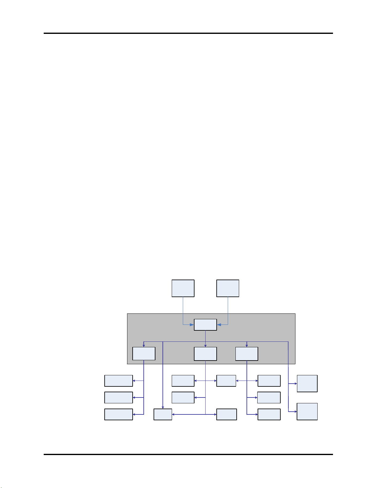
This board provides connections for both wired network and wireless adapter. In the figure
below, switch 2 always stays off during normal use. The operator can switch between wired
network and wireless adapter through the software UI. Then, the CPU applies the operator’s
selection by controlling switch 1. In configuration mode, the CPU turns off switch 1 and then
turns on switch 2 so that the operator can connect a PC to the wired network to configure the
wireless adapter.
The Ethernet wireless adapter enables the patient monitor to go wireless.
FIGURE 1-7 The ethernet wireless adapter
1 - 8 0070-10-0705 Passport V™ Service Manual
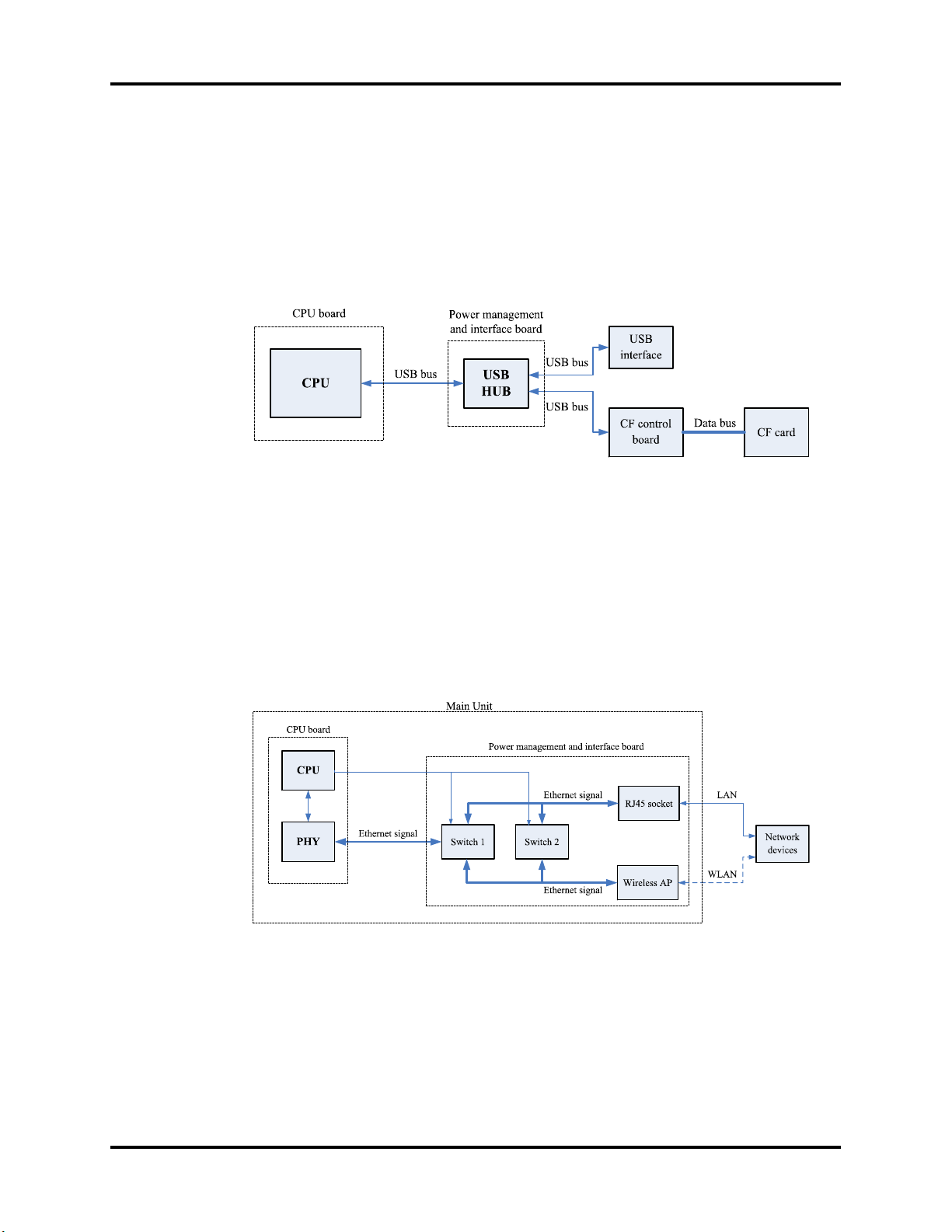
Theory of Operation Main Unit
The CPU generates analog signals by controlling the DAC chip on the power management
and interface board via the I2C bus. The analog signals are transmitted to the BNC socket
via the amplifier circuit.
FIGURE 1-8 The amplifier circuit
The signal r_flag from the multi-parameter board goes to the power management and
interface board. The CPU can select the source of defibrillator synchronization signals by
controlling the output of the DAC. The signal r_flag also goes to the CPU for a self-test.
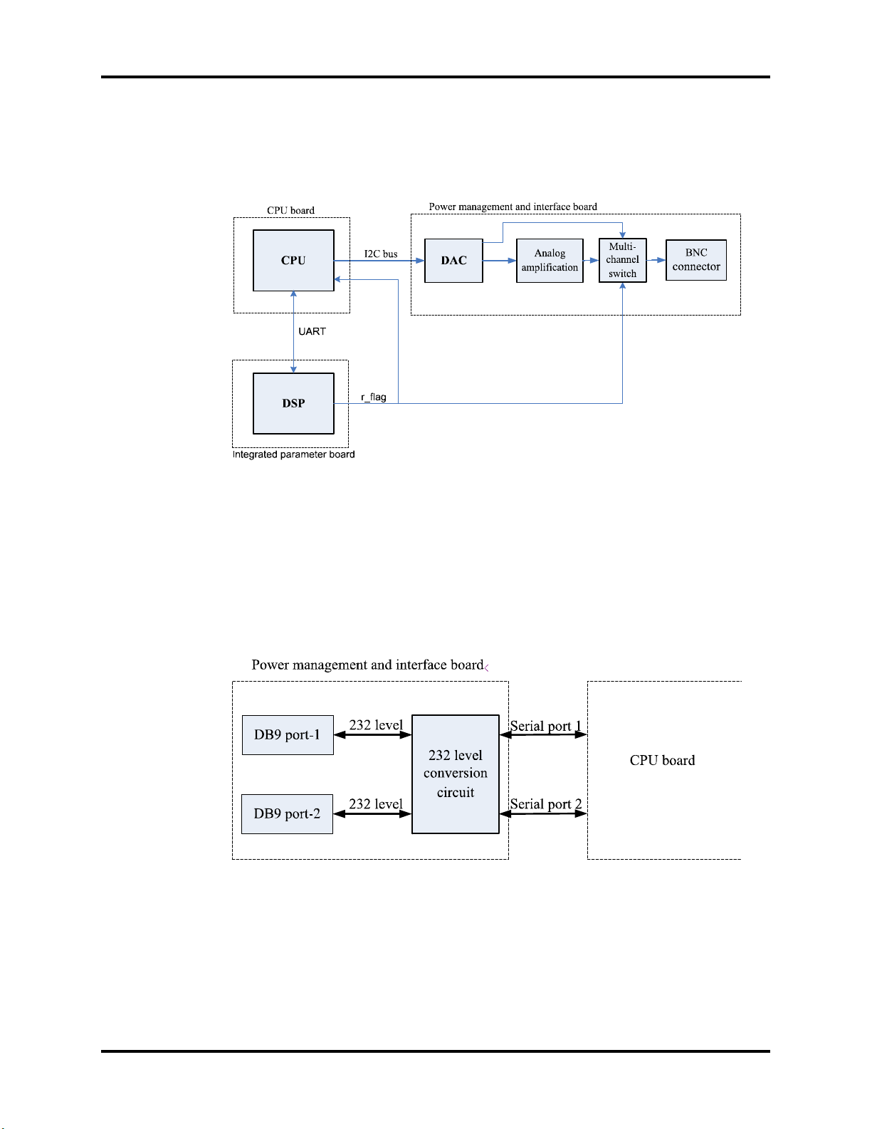
Two UART interfaces (serial port 1 and serial port 2) from the CPU board are extended as
two RS232-level ports via the power management and interface board. Both interfaces can
be configured to accommodate a PC for data or an AG module.
FIGURE 1-9 The serial ports
Passport V™ Service Manual 0070-10-0705 1 - 9

Main Unit Theory of Operation
1.3.6 Parameter modules
Multi-Parameter board
The multi-parameter board incorporates multiple parameters, such as ECG, RESP, DPM
SPO
, 2-channel IBP, TEMP, etc. Details include the following:
2
•The multi-parameter board employs a high-speed DSP, making digital filtering, arrhythmia
analysis, and ST analysis faster and more effective.
• The DSP is in charge of 3- and 5-lead ECG monitoring, arrhythmia and ST analysis, RESP
monitoring, and communicating with the CPU board.
•The multi-parameter board also employs an MCU, which supports 1-channel temperature
measurement, DPM SpO
measurement data to the DSP.
•Respiration rate is monitored using the impedance method and can only be measured
with two ECG leads.
•The multi-parameter board integrates the DPM SpO2 circuit. If a monitor is configured
with an OEM SpO
CO2 Module
, and 2-channel IBP measurement. The MCU transfers all the
2
module, then DPM SpO2 functions are overridden.
2
•There are two types of CO2 modules: DPM CO2 and Microstream CO2.
•The DPM CO2 module measures the CO2 concentration using the NDIR technology. It
performs a zero calibration periodically to ensure accurate measurements for a long
period of time. An appropriate compensation can be applied according to the patient
environment, thus preventing measurements from being influenced by interfering gases.
•The Microstream CO
module ensures that measurements will not be affected by other
2
gases and the accuracy can be maintained without any gas compensation. Additionally,
the module has a very low sample flow rate, reducing its effect on the patient and the
environment to a minimum.
OEM SpO
There are two types of OEM SpO
Module
2
modules: Masimo-2013 SpO2 module and Nellcor SpO2
2
module.
An isolation power board is attached to each of them and used to isolate the DC power and
the UART signal of the OEM SpO
modules from other circuits in the main unit. The UART
2
signal comes from the CPU board and passes through the power management and interface
board.
1 - 10 0070-10-0705 Passport V™ Service Manual
Theory of Operation Main Unit
CUFF
PRESSURE
SENSOR
PRESSURE
SENSOR
FOR
PROTECT
PRESSURE
SIGNAL
AMPLIFIER
CIRCUITS
PRESSURE
SIGNAL
AMPLIFIER
CIRCUITS
FOR
PROTECT
CPU
ASYCHRONOUS
SERIAL
COMMUNICATION
WATCHDOG
OVER
PRESSURE
PROTECT
CIRCUIT
A/D
CONVERTER
PRESSURE
SIGNAL
MOTOR CONTROL
FEEDBACK SIGNAL
PUMP AND
VALVE
CONTROL
CIRCUIT
FLASH DRAM
MANIFOLD
VALV ES
AND PUMP
NIBP Module
The figure below shows the NIBP module parameter board diagram.
FIGURE 1-10 The NIBP module parameter board
The Passport V calculates NIBP values using the oscillometric method of noninvasive blood
pressure measurement. These measurements correspond to comparisons with auscultatory
values, measured using the fifth Korotkoff sound within ANSI/AAMI SP10 standards for
accuracy.
Passport V™ Service Manual 0070-10-0705 1 - 11

Main Unit Theory of Operation
This page intentionally left blank.
1 - 12 0070-10-0705 Passport V™ Service Manual

2.0
Block Diagrams
2.1 Introduction
The Block Diagrams indicate the internal organization of the instrument. The block diagrams are used to
gain both familiarity with the instrument and to locate malfunctioning PC boards as readily as possible.
DESCRIPTION PART NUMBER
NIBP Module 6100-30-86329
Masimo SpO
Nellcor SpO2 Module 6100-30-86336
Microstream CO
DPM CO
Power board(AC/DC) 9211-30-87311
Alarm LED Board 9211-30-87306
Battery interface board assembly 9211-30-87331
Keypad Overlay 6100-20-86264-XX or
Keypad 6100-20-86265-XX
Main board 9211-20-87303
Power management and interface board 6100-20-86294
Back light board 022-000001-00
LCD Display 0000-10-11092
Recorder 6101-30-46619
Wireless AP Module 6100-30-86332
CF card assembly 6100-30-86330
Power Switch with Cable Assembly 6100-21-86306
Speaker 020-000001-00
Fan Assembly 6100-21-86315
Module 6100-30-86335
2
Module 6100-30-86333
2
Module 6100-30-86334
2
6100-20-86341-XX
NOTE: See Isometric Drawings and Parts List for a complete list of
Part Numbers.
Passport V™ Service Manual 0070-10-0705 2 - 1
2 - 2 0070-10-0705 Passport V™ Service Manual
Block Diagram Block Diagrams
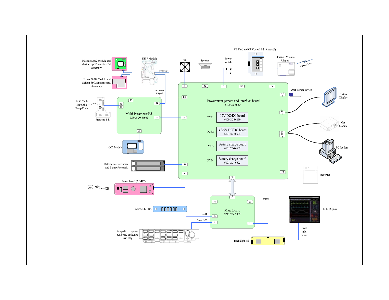
2.2 Block Diagram
FIGURE 2-1 Passport V Block Diagram

3.0
Repair Information
3.1 Introduction
This chapter provides the necessary technical information to perform repairs on the
Passport V. The most important prerequisites for effective troubleshooting are a thorough
understanding of the instrument functions as well as understanding the theory of operation.
3.2 Safety Precautions
In the event the instrument covers are removed, observe the following warnings and
guidelines.
1. Do not short component leads together.
2. The instrument covers must not be removed by anyone other than qualified technical
personnel who have received supplementary instructions regarding maintenance of
medical equipment or have equivalent experience in this area.
WAR N I NG: In t e rnal El e c trical S hock Ha zard - This unit does not contain
any user-serviceable parts. Do not remove instrument
covers. Refer Servicing to qualified personnel.
WAR N I NG: Wh e n ever th e monito r is open e d for c a l ibratio n or rep a i r, a
risk (leakage) current safety check and a verification of
basic functions of all parameters should be performed
before the monitor is returned to Clinical use. See
“Verification” on page 5-12.
Passport V™ Service Manual 0070-10-0705 3 - 1

Troubleshooting Guidelines Repair Information
3.3 Troubleshooting Guidelines
1. Identify the problem
Due to the wide variety of potential symptoms, certain problems may be more subtle
than others. One approach to troubleshooting is to set up the instrument as described in
Chapter 5.0. Following the guidelines of the tests will help determine the problem if one
exists.
2. Avoid shorting component leads
During repair procedures, it can become tempting to make a series of quick
measurements. Always turn the power off before connecting and disconnecting the test
leads and probes. The accidental shorting of leads can easily stress the components and
cause a second failure (aside from the safety risk).
3. Use the Proper equipment
The equipment listed below is suggested to fulfill a wide range of troubleshooting
requirements. It is imperative to use the designated equipment in order to ensure proper
results of any and all test procedures.
4. Clean up the repair area
After any repair, especially after any soldering or desoldering, clean off the repair area
with alcohol and a stiff brush. This will remove any residual solder flux, in turn allowing
the instrument to return to its original appearance.
3.4 Special Tools Required
•Digital Voltmeter
•Digital Mercury Manometer – 0 to 300 mmHg
•Safety Analyzer
•Patient Simulator
•Test Chamber / Dummy Cuff (P/N 0138-00-0001-01 (700 cc) or -03 (500 cc))
•Desktop PC or notebook PC.
•Microsoft Windows 2000/XP operating system
•Intel Pentium CPU, above 500MHz
•Above 128M memory
•At least one network card and at least one USB port
•CAT-5 crossover cable
• USB cable or DPM SB storage device
3.5 Disassembly Instructions
Before disassembling the unit, perform the following:
•Power down the unit and remove the line cord.
•Remove all cable assemblies from the left side, right side, and rear of the unit.
•Remove any batteries that were installed.
•Perform all work on a properly grounded ESD workstation.
3 - 2 0070-10-0705 Passport V™ Service Manual
Repair Information Disassembly Instructions
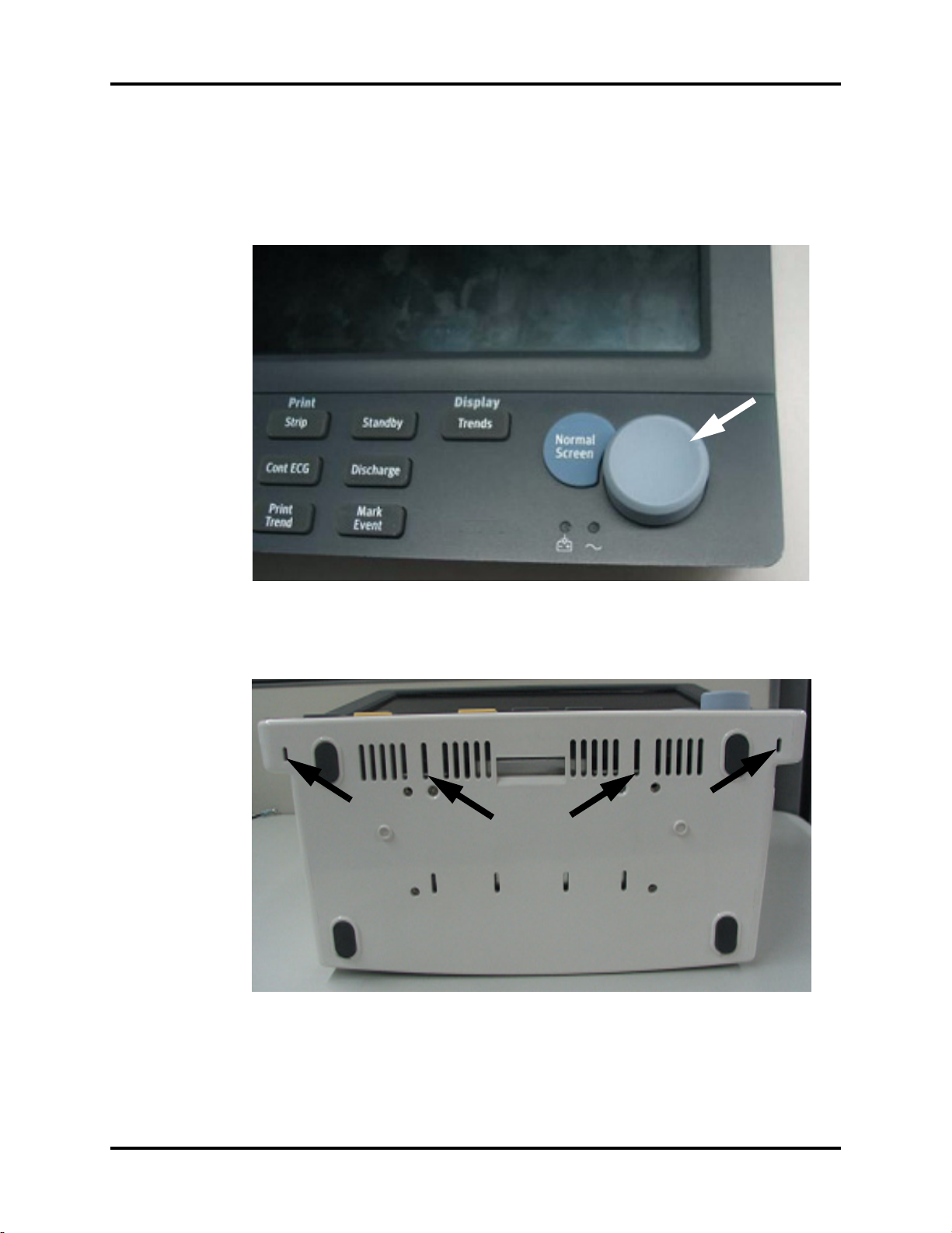
3.5.1 Removal of the Key Panel and Keys
1. Place the unit on a protective surface.
2. Carefully remove the knob with a pair of pliers that have protection on the jaws. Some
pliers may damage the knob.
FIGURE 3-1 Remove the knob
3. Release the key panel’s four clips from the bottom of the unit with a flat-bladed
screwdriver.
FIGURE 3-2 Release the key panel clips
4. Remove the key panel from the front.
5. Remove the keys and place to the side with the key panel.
Passport V™ Service Manual 0070-10-0705 3 - 3

Disassembly Instructions Repair Information
3.5.2 Removal of the Front Housing Assembly
1. Place the unit face down on a protective surface.
2. Remove the six screws from the rear of the unit.
FIGURE 3-3 Remove the screws from the rear of the unit
3. Turn the unit over and carefully separate the front housing assembly and rear housing
assembly.
4. Disconnect the 50-pin ribbon cable from the front housing assembly.
FIGURE 3-4 Disconnect the ribbon cable from the front housing assembly
5. Remove the front housing assembly.
3 - 4 0070-10-0705 Passport V™ Service Manual
Repair Information Disassembly Instructions
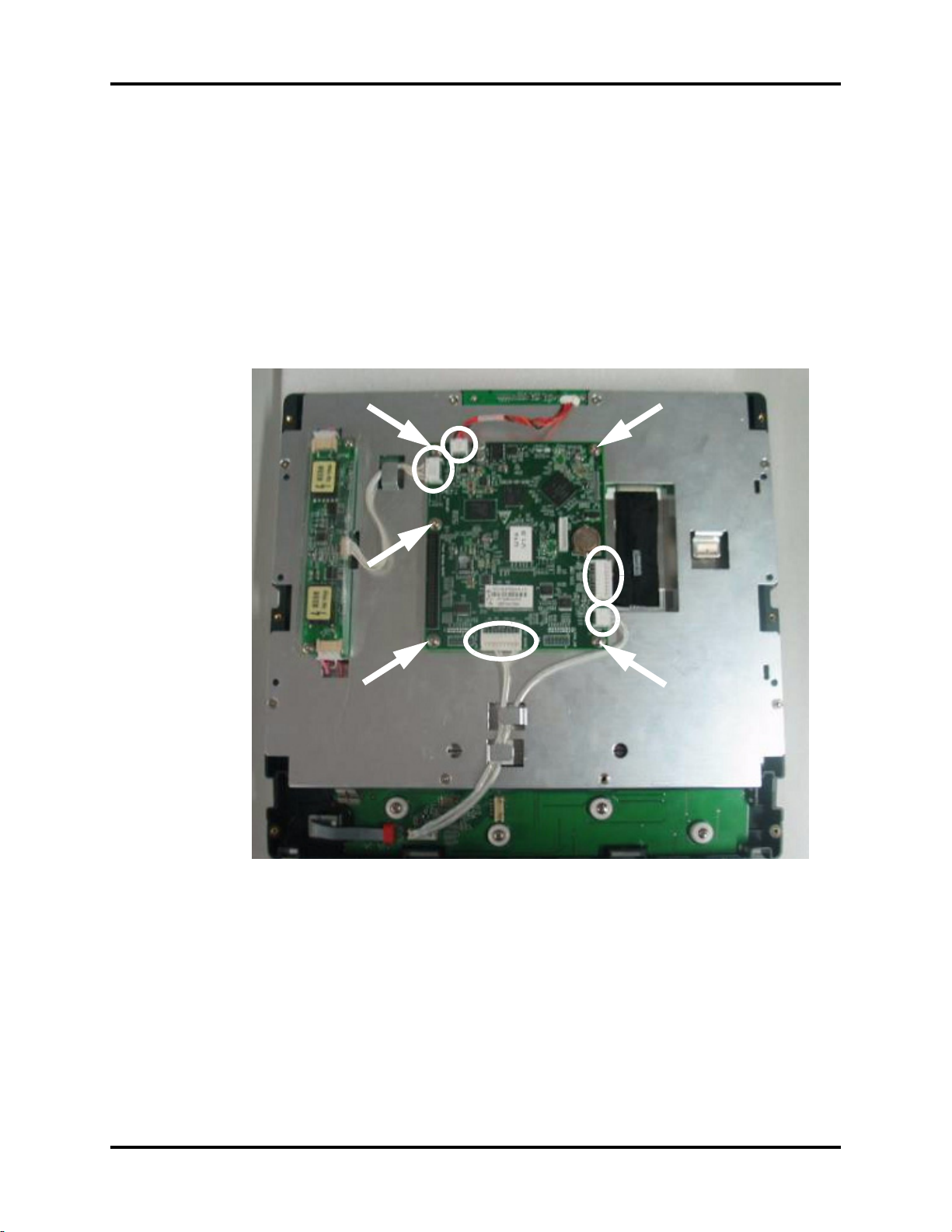
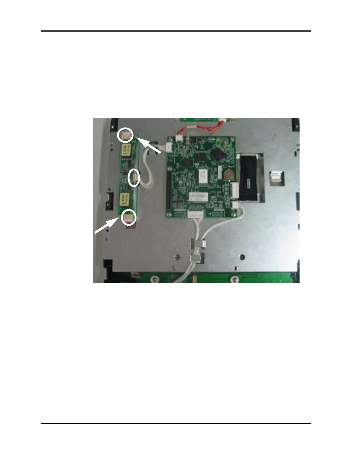
3.5.3 Removal of the Main Board
1. Remove the front housing assembly as stated in “Removal of the Front Housing
Assembly” on page 3-4.
2. Remove the keyboard cable.
3. Remove the inverter cable.
4. Remove the LCD panel cable.
5. Remove the alarm LED board cable.
6. Remove the five screws that secure the main board to the front housing bracket.
7. Remove the main board carefully.
FIGURE 3-5 Remove the main board
Passport V™ Service Manual 0070-10-0705 3 - 5
Disassembly Instructions Repair Information
3.5.4 Removal of the Inverter
1. Remove the front housing assembly as stated in “Removal of the Front Housing
Assembly” on page 3-4.
2. Remove the inverter cable.
3. Remove the two backlight board cable from the inverter.
4. Remove the two screws that secure the inverter to the front housing bracket.
5. Remove the inverter carefully.
FIGURE 3-6 Remove the inverter
3 - 6 0070-10-0705 Passport V™ Service Manual
Repair Information Disassembly Instructions
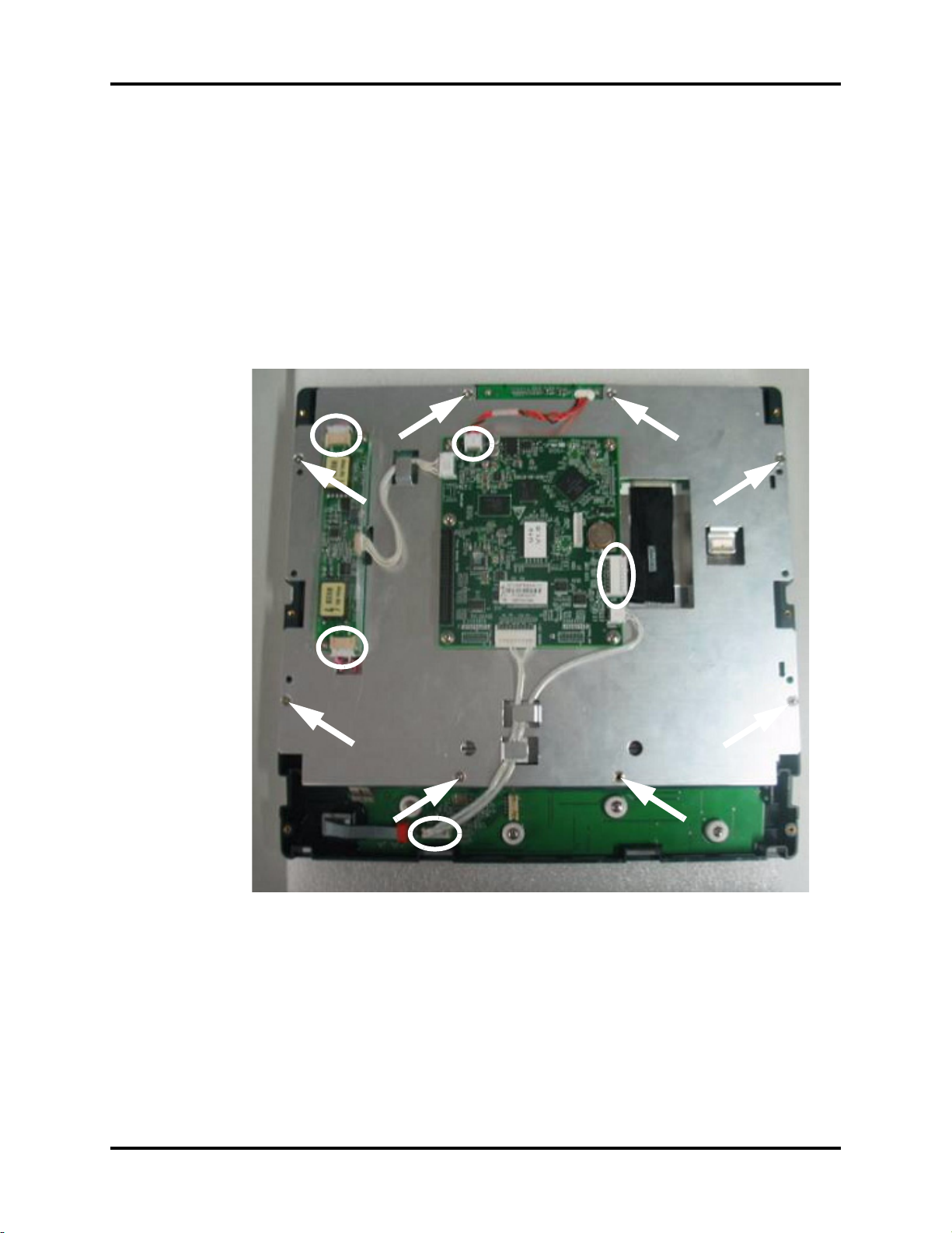
3.5.5 Removal of the LCD Panel
1. Remove the front housing assembly as stated in “Removal of the Front Housing
Assembly” on page 3-4.
2. Remove the two backlight board cables from the inverter.
3. Remove the keyboard cable.
4. Remove the alarm LED board cable.
5. Remove the LCD panel cable.
6. Remove the eight screws that secure the front housing bracket.
7. Remove the front housing bracket and place to the side.
FIGURE 3-7 Remove the LCD panel
Passport V™ Service Manual 0070-10-0705 3 - 7
 Loading...