


BS-300
Chemistry Analyzer
Service Manual


© 2006 Shenzhen Mindray Bio-medical Electronics Co., Ltd. All rights Reserved.
For this Service Manual, the issued Date is 2006-06 (Version: 1.0).
Intellectual Property Statement
SHENZHEN MINDRAY BIO-MEDICAL ELECTRONICS CO., LTD. (hereinafter called
Mindray) owns the intellectual property rights to this Mindray product and this
manual. This manual may refer to information protected by copyrights or patents and
does not convey any license under the patent rights of Mindray, nor the rights of
others. Mindray does not assume any liability arising out of any infringements of
patents or other rights of third parties.
Mindray intends to maintain the contents of this manual as confidential information.
Disclosure of the information in this manual in any manner whatsoever without the
written permission of Mindray is strictly forbidden.
Release, amendment, reproduction, distribution, rent, adaption and translation of this
manual in any manner whatsoever without the written permission of Mindray is
strictly forbidden.
, , , , are the registered
trademarks or trademarks owned by Mindray in China and other countries. All
other trademarks that appear in this manual are used only for editorial purposes
without the intention of improperly using them. They are the property of their
respective owners.
Responsibility on the Manufacturer Party
Contents of this manual are subject to changes without prior notice.
All information contained in this manual is believed to be correct. Mindray shall not
be liable for errors contained herein nor for incidental or consequential damages in
connection with the furnishing, performance, or use of this manual.
Mindray is responsible for safety, reliability and performance of this product only in
the condition that:
all installation operations, expansions, changes, modifications and repairs of this
product are conducted by Mindray authorized personnel;
the electrical installation of the relevant room complies with the applicable
national and local requirements;
the product is used in accordance with the instructions for use.
WARNING:
It is important for the hospital or organization that employs this
equipment to carry out a reasonable service/maintenance plan.
Neglect of this may result in machine breakdown or injury of human
health.
NOTE:
This equipment is to be operated only by medical professionals trained
and authorized by Mindray or Mindray-authorized distributors.
I

Warranty
THIS WARRANTY IS EXCLUSIVE AND IS IN LIEU OF ALL OTHER WARRANTIES,
EXPRESSED OR IMPLIED, INCLUDING WARRANTIES OF MERCHANTABILITY
OR FITNESS FOR ANY PARTICULAR PURPOSE.
Exemptions
Mindray's obligation or liability under this warranty does not include any
transportation or other charges or liability for direct, indirect or consequential
damages or delay resulting from the improper use or application of the product or the
use of parts or accessories not approved by Mindray or repairs by people other than
Mindray authorized personnel.
This warranty shall not extend to:
any Mindray product which has been subjected to misuse, negligence or
accident;
any Mindray product from which Mindray's original serial number tag or product
identification markings have been altered or removed;
any product of any other manufacturer.
Return Policy
Return Procedure
In the event that it becomes necessary to return this product or part of this product to
Mindray, the following procedure should be followed:
1 Obtain return authorization: Contact the Mindray Service Department and
obtain a Customer Service Authorization (Mindray) number. The Mindray
number must appear on the outside of the shipping container. Returned
shipments will not be accepted if the Mindray number is not clearly visible.
Please provide the model number, serial number, and a brief description of
the reason for return.
2 Freight policy: The customer is responsible for freight charges when this
product is shipped to Mindray for service (this includes customs charges).
3 Return address: Please send the part(s) or equipment to the address offered
by Customer Service department
Company Contact
Manufacture: Shenzhen Mindray Bio-Medical Electronics Co., Ltd.
Address:
Phone:
Fax:
Mindray Building, Keji 12th Road South, Hi-tech Industrial Park,
Nanshan, Shenzhen, P.R.China, 518057
+86 755 26582479 26582888
+86 755 26582500 26582501
II

Preface
Who Should Read This Manual
This manual is written for service professionals authorized by Mindray.
Conventions Used in This Manual
Safety Symbols
This chart explains the symbols used in this manual.
When you see … Then …
WARNING:
Read the statement following the symbol. The
statement is alerting you to an operating hazard
that can cause personal injury.
BIOHAZARD:
CAUTION:
NOTE:
Read the statement following the symbol. The
statement is alerting you to a potentially
biohazardous condition.
Read the statement following the symbol. The
statement is alerting you to a possibility of
system damage or unreliable results.
Read the statement following the symbol. The
statement is alerting you to information that
requires your attention.
Graphics
All graphics, including screens and printout, are for illustration purpose only and
must not be used for any other purposes.
i


Contents
Contents
Preface........................................................................................................................................... i
Who Should Read This Manual .............................................................................................. i
Conventions Used in This Manual .......................................................................................... i
1 Specifications....................................................................................................................1-1
1.1 System Feature...................................................................................................1-1
1.2 Loading System Feature .....................................................................................1-1
1.3 Analysis System Feature.....................................................................................1-2
1.4 Others..................................................................................................................1-2
2 System Installation...........................................................................................................2-1
2.1 Check before Installation.....................................................................................2-1
2.2 Installation Procedure..........................................................................................2-1
3 System Descriptions ........................................................................................................3-1
3.1 Dispensing System..............................................................................................3-1
3.1.1 Probe assemblies.................................................................................3-1
3.1.2 Disk assemblies ...................................................................................3-2
3.2 Feeder .................................................................................................................3-3
3.2.1 Feeder assemblies...............................................................................3-3
3.2.2 Manipulator...........................................................................................3-4
3.3 Temperature Control System...............................................................................3-5
3.3.1 Temperature control assembly.............................................................3-5
3.3.2 Reagent preheating..............................................................................3-6
3.3.3 Reagent refrigeration............................................................................3-7
3.4 Photometric System ............................................................................................3-8
3.5 Fluid System........................................................................................................3-8
3.6 ISE Module (optional)........................................................................................3-10
Functions of Boards.........................................................................................................4-1
4
4.1 Main Control Board..............................................................................................4-1
4.2 Power Drive Board ..............................................................................................4-2
4.3 A/D Conversion Board.........................................................................................4-2
4.4 Reagent Refrigeration Board...............................................................................4-2
4.5 Level Detection Boards .......................................................................................4-3
4.6 Feeder Connection Board ...................................................................................4-3
4.7 Manipulator Connection Board............................................................................4-3
4.8 Probes Connection Board ...................................................................................4-4
4.9 Power Supply Assembly......................................................................................4-4
5 Maintenance and Service.................................................................................................5-1
5.1 Replacing Light Filter Assembly ..........................................................................5-1
5.2 Replacing Optical Fiber.......................................................................................5-4
5.3 Adjusting Reaction Disk, Manipulator and Feeder..............................................5-7
5.4 Adjusting Probes and Disks.................................................................................5-8
5.5 Replacing Components of ISE Unit (optional)...................................................5-10
5.5.1 Replacing Tubing................................................................................5-10
5.5.2 Replacing Pumps...............................................................................5-13
5.5.3 Replacing ISE Module........................................................................5-13
6 Software Introduction.......................................................................................................6-1
1

Contents
6.1 System Software..................................................................................................6-1
6.1.1 System initialization..............................................................................6-1
6.1.2 Shutdown processing...........................................................................6-2
6.2 Control Software..................................................................................................6-2
7 Service Flow......................................................................................................................7-1
7.1 Fluid Level Detection Failure of Reagent Probe..................................................7-1
7.2 Fluid Level Detection Failure of Sample Probe...................................................7-2
7.3 Liquid Dropping From Probes..............................................................................7-3
7.4 Failing to Detect Level of Water for Washing Exteriors.......................................7-4
7.5 Abnormal Results................................................................................................7-5
7.5.1 All Results Being Abnormal..................................................................7-5
7.5.2 Some Results Being Abnormal.............................................................7-5
7.5.3 Several Results Being Abnormal..........................................................7-6
7.6 Insufficient Light Intensity of Lamp......................................................................7-7
7.7 Temperature Control Failure................................................................................7-8
7.8 Bar Code Scanner (optional) Failure...................................................................7-9
7.9 Feeder Failure ................................................................................................... 7-11
7.9.1 Transducer Distribution of the Feeder................................................7-11
7.9.2 Feeder Failure....................................................................................7-12
7.9.3 Manipulator Failure.............................................................................7-13
7.10 Troubleshooting of ISE Unit (optional)...............................................................7-13
8 Mechanical Structure .......................................................................................................8-1
9 Tools and Parts.................................................................................................................9-1
9.1 Service Tools .......................................................................................................9-1
9.2 Parts ....................................................................................................................9-1
10
Maintenance And Test Software....................................................................................10-1
General..............................................................................................................10-1
10.1
Command ..........................................................................................................10-3
10.2
10.2.1 Single Command Area.......................................................................10-3
10.2.2 Macroinstruction Area.......................................................................10-10
10.3 PARA and Speed.............................................................................................10-13
10.4 Temperature.....................................................................................................10-19
10.5 Photoelectric....................................................................................................10-20
Appendix A Board s Connection Diag rams.............................................................................. A-1
Appendix B Test Points of Boards............................................................................................ B-1
2

1 Specifications
X
1.1 System Feature
Dimension: 980mm × 710mm × 1200mm (W × D × H)
Weight: 175kg
Power supply: AC100-130V ± 10% or 200-240V ± 10%
Input power: 1000VA
System: optional, multi-channel, multi-test
Scope: Clinical chemistries
Test types: end-point, kinetic and fixed-time. All support double-reagent and
double-wavelength
Calibration type: Linear (single-point, two-point and multi-point), Logistic 4P,
Logistic 5P, Exponential 5P, Polynominal 5P, Parabola, Spline
QC rules: Westgard multi-rule,
Twin-plot
Tests analyzed simultaneously: 48 (single-reagent) / 24 (double-reagent); if the
ISE unit (optional) is connected, 3 (Na, K and Cl included) or 4 (Na, K, Cl and Li
included) tests are added
Throughput: maximum 300tests/h; if the ISE (optional) is connected, maximum
420tests/h (Na, K and Cl included) or maximum 480 tests/h (Na, K, Cl and Li
included)
Specifications
−
-R, Cumulative sum check, Cumulative error,
1.2 Loading System Feature
Sample volume: 3µl~45µl; Precision: 0.5µl; for the ISE (optional), 70µl serum,
70µl plasma, 140µl diluted urine
Sample disk: general sample disk, including the inner circle and the outer circle
Sample tube position: 60 positions, including 6 calibrator positions, 3 control
positions, 5 for STAT sample positions; 5 virtual disks for maximum 300 samples
Sample probe: with a built-in level detector; equipped with auto safeguard;
capable of tracking sample level
Washing function: automatically washing interior and exterior of sample probe;
carryover no more than 0.1%
Pre-dilution: 4 ≤ dilution rate ≤ 150, taking reaction cuvettes as the container
Reagent volume: 30-450ul; Precision: 1ul
Reagent disk: including the inner circle and the outer circle
Reagent position number: 25/50 reagent positions. Each reagent position is
available for containing one Hitachi 7060 bottle, one Hitachi 7170 bottle, one
Mindray inner-circle bottle or one Mindray outer-circle bottle.
Reagent probe: One independent probe which has a built-in level detector; is
equipped with auto safeguard and capable of tracking reagent level
Washing function: automatically washing interiors and exteriors of reagent probes;
carryover no more than 0.1%
1-1
1-

Specifications
Mixing bar: for single-reagent tests, it functions after sample dispensing; for
double-reagent tests, it functions after the dispensing of the sample and the
second reagent.
1.3 Analysis System Feature
Lamp house: 50w lamp
Light splitting mode: Splitting by optical fiber, filtering by an interference filter.
Half band-width: 10±2nm
Wavelength: 340, 405, 450, 510, 546, 578, 630, 670, 700nm
Absorbance range: -0.1~5, 10mm optical path conversion
Reaction cuvette: 5 × 6 × 25mm, optical path 5mm. Material: PP, disposable.
Volume: 750uL
Reaction liquid volume: 180-500µl
Max. reaction time: 20 minutes
Reaction temperature: 37±0.3℃ with fluctuation of ±0.1℃
1.4 Others
Operating system: Windows 2000 or Windows XP
Display: optional
System interface: RS-232
Printer: optional
Built-in bar code scanner: optional
ISE module: optional
1-2

2 System Installation
NOTE:
The analyzer should be installed or moved to another place by
Mindray-authorized personnel only.
2.1 Check before Installation
The user should provide the environment that meets the requirements mentioned in
the Operation Manual. Check if the environment meets the requirements before
installing the analyzer . Refer to the chapter 2 of the Operation Manual for details.
2.2 Installation Procedure
System Installation
1 Ensure available installation fields and environments in hospitals.
2 Confirm the reagents and calibrators.
3 Go to the installation field, and then check the delivery list for acceptance.
4 Install the four handles on the four angles of the analyzer. Move the analyzer
to the installation field, fix the casters, and then remove the handles.
5 Insta ll the computer, display and printer.
6 Open the front plate, and check whether cable connections are loose. Open
the top plate, check whether the probe assemblies, reagent disk and sample
disk are intact and in good performance.
7 Connect the communication cable, power cable, grounding wire, waste tank
and deionized water tank. Install the used-cuvette bucket, reagent probe,
sample probe and mixing bar.
8 Top up the deionized water tank with deionized water.
9 Put reaction cuvettes in the feeder. Remember to check whether the surfaces
of the cuvettes are smooth. In case of any bump, remove it before loading the
cuvette to the compartment. Do not touch the light transmission part of the
cuvette in which the colorimetric reading is taken.
10 Load acid and alkaline detergents to positions 46 and 47, and distilled water
to positions 49 on the reagent disk. Load distilled water to position 60 on the
sample disk.
11 Switch on the analyzer as follows: POWER → ANALYZING UNIT POWER
→display → computer → printer.
12 After Windows is started, double-click the icon of BS-300 on the desktop to
start the system software. The system program will automatically finish the
self-test, become online and warm up the reaction cuvettes within about 30
minutes.
13 Select the [System/Status] menu, and then observe the system status and
record it in the table below:
2-1
System Installation
Feeder status Unconnected Full Half full Empty
Reaction disk
temperature
Reagent disk
temperature
Ambient temperature
Waste tank status Abnormal (full) Normal (not full)
Detergent status Abnormal (empty) Normal (available)
Printer status No printer Normal
Main control unit Unconnected Idle Running
Reaction disk unit Unconnected
Reagent disk unit Unconnected
Sample disk unit Unconnected
Loading/unloading unit Unconnected
Temperature control
unit
Lamp
Unconnected
Network connection Unconnected
Wavelength Dark current Light source base
340
405
450
510
546
578
630
670
700
Reference light system
14 Select the [System/Maintenance] menu. Then select the Motion tab page,
and implement all sub-steps of each unit to see whether they are normal. In
case of any exception, adjust it.
15 Wash the interiors and exteriors of the sample probe, reagent probe and
mixing bar for several times to make the fluid circuit filled.
16 Set parameters for test, reagent and calibration under the Parameters menu.
2-2
System Installation
17 Request for calibration and samples, run and then debug the results.
18 After debugging the results, fill them in the table below:
Test ALT CREA BUN
Target value
2sd range
Test value 1
Test value 2
Test value 3
Test value 4
Test value 5
Test value 6
Test value 7
Test value 8
Test value 9
Test value 10
19 Training
Can the user complete daily tests? Yes □ No □
Is the user familiar with the analytical methods such as
kinetic, two-point, endpoint?
Is the user familiar with the daily, weekly and monthly
maintenance and relevant maintenance methods?
Is the user skilled in washing dust screens? Yes □ No □
Is the user skilled in cleaning and replacing the probes
and the mixing bar?
Is the user skilled in replacing the plunger assemblies
of syringes?
Is the user skilled in replacing the lamp? Yes □ No □
Is the user skilled in maintenance of built-in bar code
scanner?
Is the user skilled in maintenance of ISE unit? Yes □ No □
Does the user know the positions, roles and
preparation methods of distilled water and acid and
alkaline detergents?
Yes □ No □
Yes □ No □
Yes □ No □
Yes □ No □
Yes □ No □
Yes □ No □
2-3

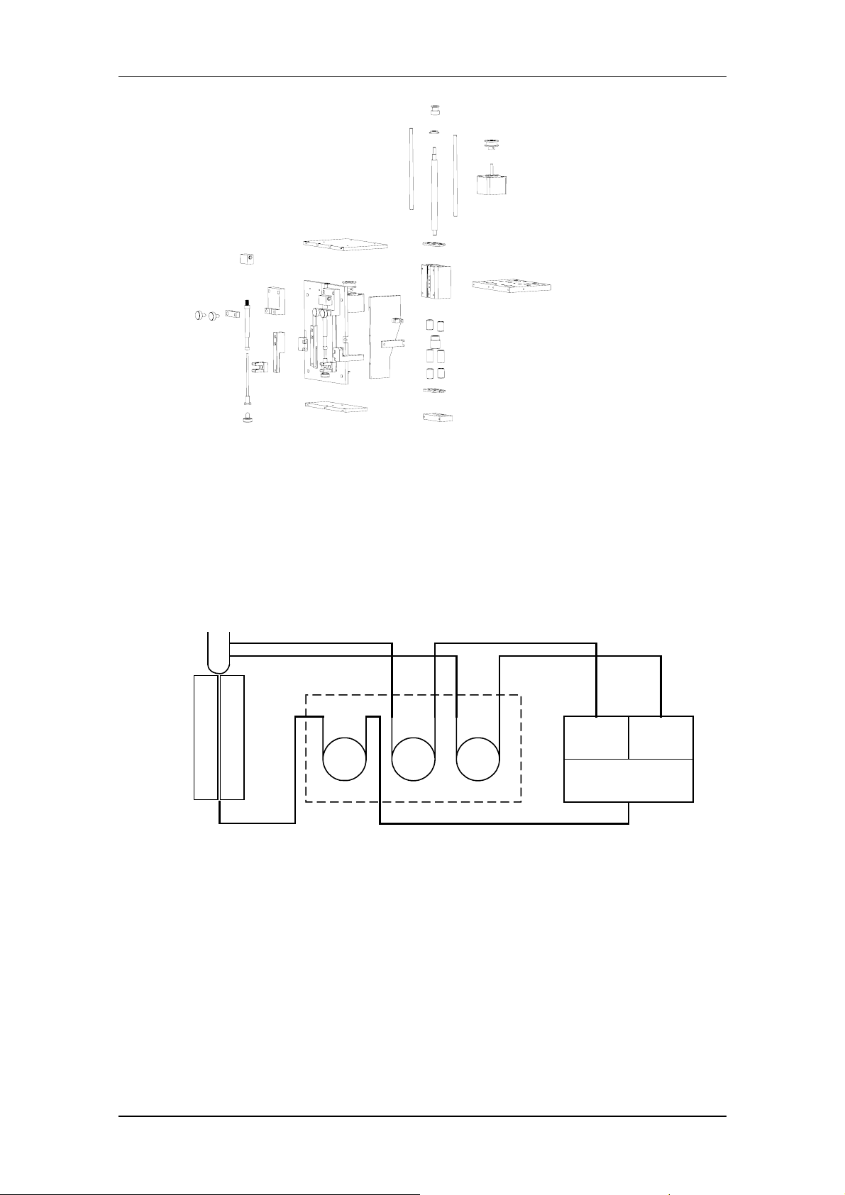
3 System Descriptions
The BS-300 analyzer consists of the analyzing unit, operation unit and output unit.
The analyzing unit consists of the dispensing system, feeder, temperature control
system, photometric system and fluid system.
3.1 Dispensing System
The dispensing system consists of the probe assemblies (including the reagent
probe assembly, sample probe assembly and mixing bar assembly), reagent disk,
sample disk and reaction disk.
3.1.1 Probe assemblies
System Descriptions
Among the probe assemblies, the mixing bar assembly is the same as the reagent
probe assembly and the sample probe assembly, except that the knurled axis is
30cm shorter.
Every probe assembly has a horizontal photoelectric switch and a vertical
photoelectric switch. These switches are used for defining horizontal and vertical
3-1
System Descriptions
initial positions of probe assemblies. The horizontal and vertical step motors
precisely control the horizontal and vertical movements of the probe assemblies, and
the synchronizing belts serve as the gearing.
The shaft and the bushing must corporate with each other precisely, so they cannot
be used confusedly.
3.1.2 Disk assemblies
The three disk assemblies are different in their coders. The coder corresponds to the
position where disks should stop. There is an initial-position mark under every coder.
The three coders of the three disks have three coder transducers. Each transducer
has two photoelectric switches for inducing the rotation and initial position of the
disk.
The step motors control the disk assemblies, and the synchronizing belts serve as
the gearing.
3-2

System Descriptions
There is a build-in bar code scanner to the left of the sample disk. The scanner is
optional.
3.2 Feeder
The feeder consists of the feeder assemblies and the manipulator. It is designated to
send cuvette segments to the reaction disk, take out the used ones and abandon
them to the used-cuvette bucket.
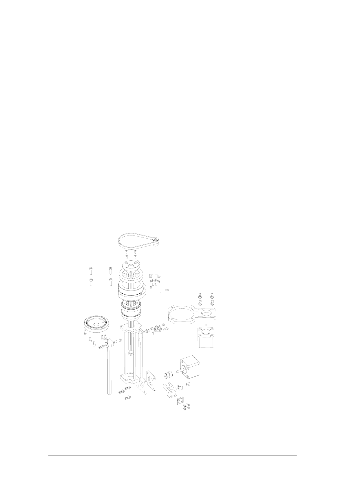
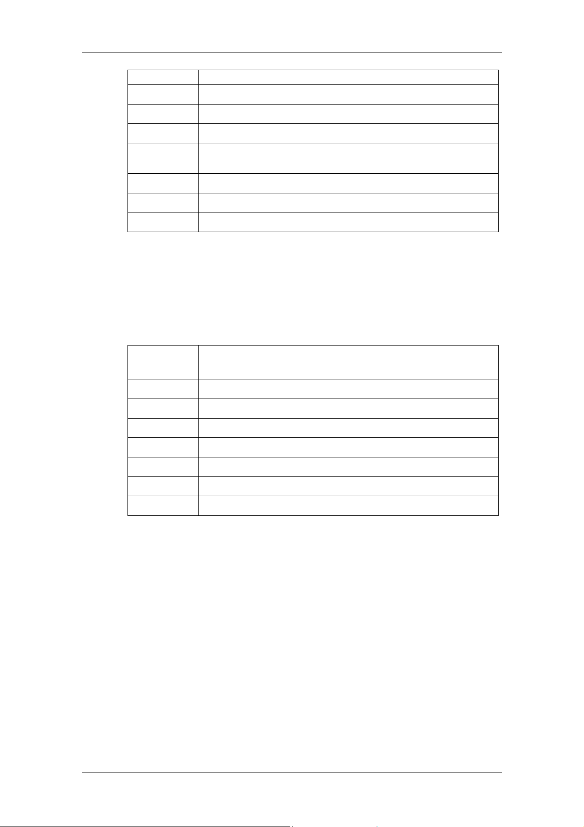
3.2.1 Feeder assemblies
The feeder assemblies include the gearing assembly, cuvette compartment
assembly, cuvette-pushing assembly and no-cuvette detection assembly (see the
following figure).
The supporting plate of the feeder assemblies is a square piece of steel that is
connected to the analyzing unit by its four poles, which are secured by four nuts.
Unscrewing the nuts, you can disassemble the feeder assemblies from the analyzing
unit easily.
Sample probe assemblyBuild-in bar code scanner
3-3
System Descriptions
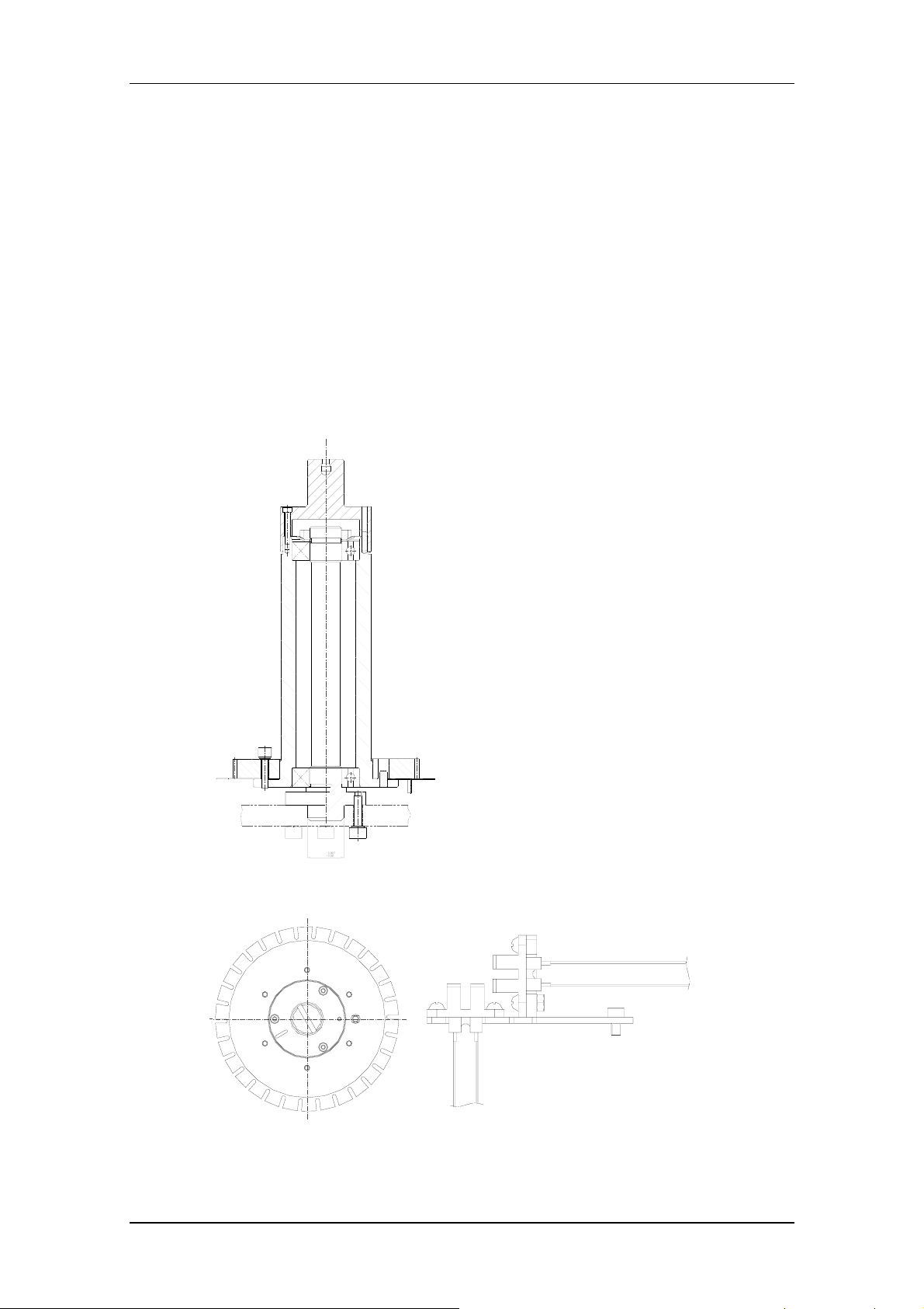
There are five transducers that are shown in the figure below.
The no-cuvette transducer is used to detect whether there is a cuvette segment at
the loading position. The insufficient-cuvette transducer is used for determine
whether there are less than 10 reaction cuvettes in the compartment or not. If yes,
the analyzer will give a prompt.
Pressure Transducer
No-Cuvette
Transducer
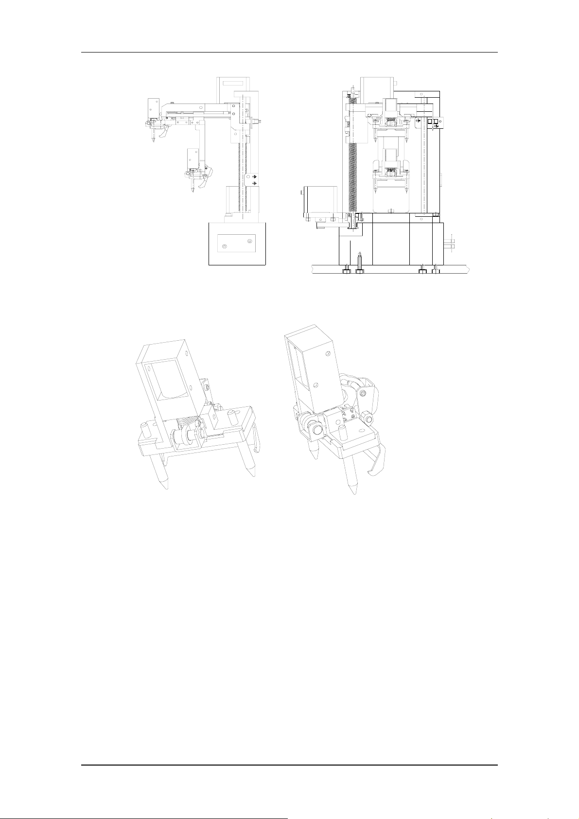
3.2.2 Manipulator
Two step motors (horizontal and vertical) supply power for horizontal and vertical
movements of the manipulator.
The upper finger and lower finger are same in their structures. They work together to
replace used cuvette segments with new ones.
The manipulator runs in a relatively complicated way. There are four transducers on
it: vertical transducer, horizontal transducer and two finger transducers.
Cuvette-Pushing
Limit Transducer
Insufficient-Cuvette
Transducer
Cuvette-taking limit
transducer
3-4
System Descriptions
3.3 Temperature Control System
3.3.1 Temperature control assembly
The temperature control assembly of the reaction disk consists of the
temperature-controlled pot, heat-insulating sheath/plate, top heater, bottom heater,
reaction disk/cuvettes, photoelectric seat, temperature transducer, fan and control
circuit.
3-5

System Descriptions
1: Temperature transducer and the support
2: Fan
3: photoelectric seat
4: Heat-insulating sheath
5: top heater
6: Cover
7: temperature-controlled pot
8: bottom heater
Upper heater: square in shape, 220/110VAC, 125W
Lower heater: ring in shape, 220/110VAC, 350W
Total power: 475W.
The function of heaters is to compensate the heat for incubating the reagent and for
maintaining the temperature of the temperature-controlled chamber .
Fans are used in series in the temperature-controlled chamber. It makes the air
circulating in the chamber, and enhances the convective heat exchange. There are
four fans in the chamber. All have the alarm function.
The temperature transducer feeds back the air temperature at the position several
millimeters from the bottom of the reaction cuvette.
The overheat protection switch is to switch off the power when the temperature
controller does work and the temperature-controlled chamber reaches 55℃, so as to
avoid overheat or fire. When the temperature-controlled chamber becomes 35℃,
this switch will automatically be reset.
3.3.2 Reagent preheating
The preheating assembly consists of two aluminum plates, a Te flon tube having nine
loop sections, heating components, transducer, temperature protection switch,
thermal conductive colloid, a section of tube and the reagent probe.
The temperature of the thermal source of the preheater is controlled at 45℃. The
initial temperature of the reagent is 4 ~ 10℃ when it is taken out of the refrigeration
3-6

System Descriptions
chamber. When the reagent passes the heater, its temperature increases to 35℃.
Then the reagent is added into the reaction cuvette and the preheating process is
finished.
Reagent preheating assembly
3.3.3 Reagent refrigeration
The refrigeration module consists of refrigeration cabin, PU heat-insulating sheath,
reagent disk, reagent bottle, temperature transducer, refrigeration flakes, heat
sinking component, fan and control circuit. The refrigeration module is shown in the
following figure.
The refrigeration assembly consists of fan, hot-end radiator, POM connector,
cold-end heat-conductive aluminum block, and PELTIER refrigeration flake. Each
analyzer has two such refrigeration assemblies, as shown in the figure below. The
cold-side of the refrigeration flake clings to the refrigeration compartment, and the
hot-side clings to the radiator (The side having letters should cling to the refrigeration
aluminum block).
3-7
System Descriptions
Each refrigeration flake corresponds to a heat-sinking block and a cooling fan. It
should be installed with the cold side upward.
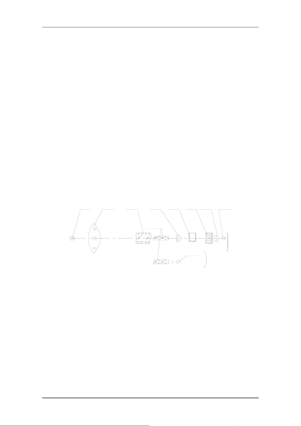
3.4 Photometric System
The photometric system consists of a measurement photometric system and a
reference photometric system. The measurement photometric system provides 9
monochromatic lights to measure the absorbance of the reacting liquid in the rotating
reaction cuvettes. The reference photometric system compensates the
measurement photometric system to make the measurement more accurate.
Tungsten-halogen
lamp
卤钨灯 聚光镜
Biconvex lens
3.5 Fluid System
The fluid system is shown in the following figure.
Main fiber
传光束
Plano
小透镜 反应杯 滤光片 小透镜 光电管
convex lens
Fibers
传光束小端
Cuvette Filter
Photodiode
convex lens
共路
光电管
Plano
参考光路
Reference light
Photodiode
测量光路
Measurement
.
.
.
lights
3-8
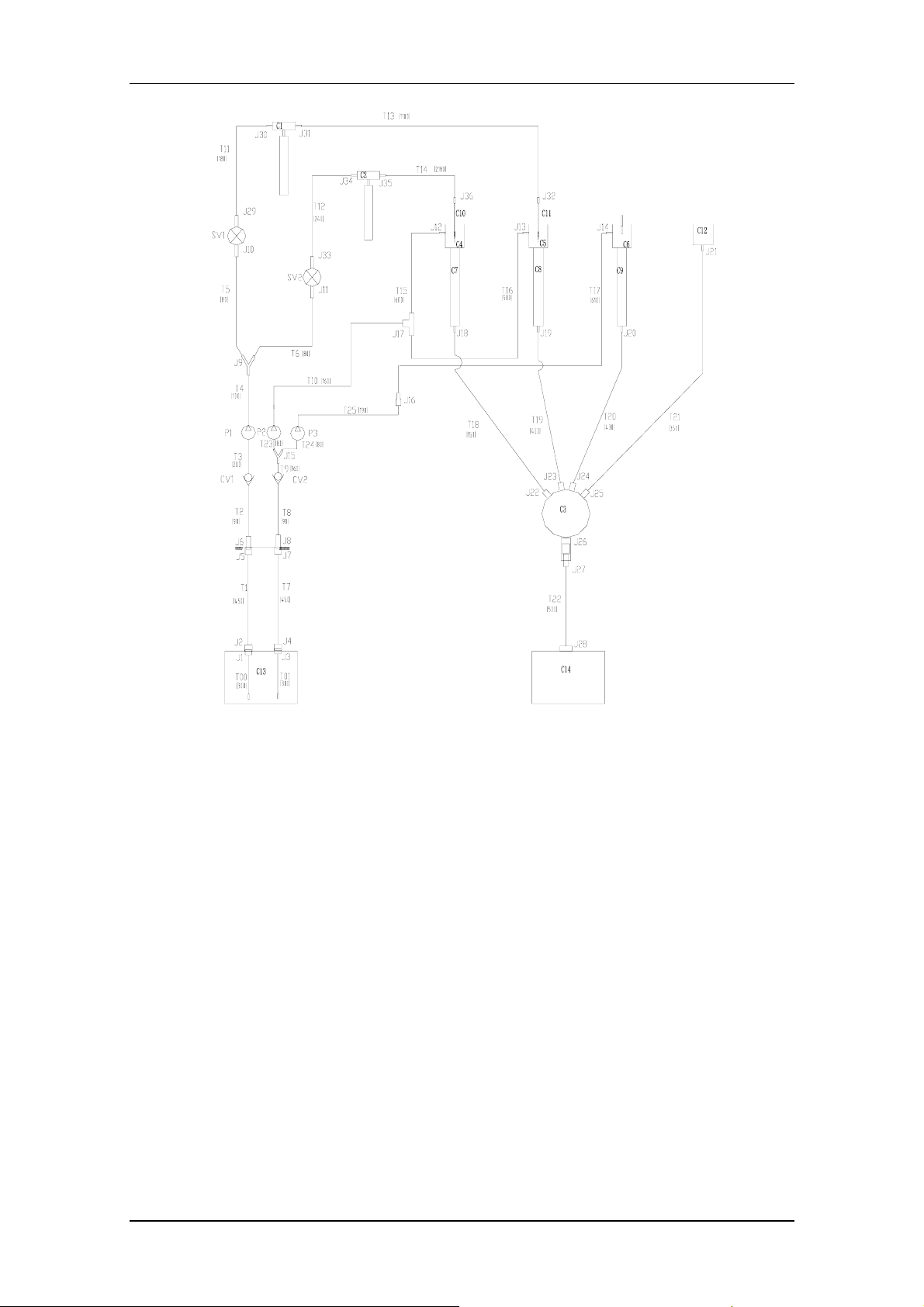
Sample syringe
System Descriptions
Reagent syringe
Mixing bar
As shown in the figure above, the fluid system consists of interior washing and
exterior washing.
The syringe assembly controls the aspiration volume by controlling the travel of the
sample/reagent syringe. It is the core part of the fluid system.
3-9
System Descriptions
3.6 ISE Module (optional)
The ISE module that is used to measure the concentration of K+, Na+, Cl- and Li+ in
serum, plasma and urine consists of ion-selective electrodes, peristaltic pumps and
calibrants.
ISE
Pump W
Calibrant B
Pump BPump A
Calibrant A
Waste
3-10

System Descriptions
3-11

4 Functions of Boards
The analyzer is integrated with the following boards:
Main control board
Power drive board
Sample level detection board
Reagent level detection board
A/D conversion board
Ten photoelectric conversion boards (340nm, 405nm, 450nm, 510nm, 546nm,
578nm, 630nm, 670nm, 700nm and reference light)
Reagent refrigeration board
Power supply assembly
Manipulator connection board
Feeder connection board
Probes connection board
Functions of Boards
Power supply assembly
PFC board
12V&5V board
24V board
ISE power supply board
A/D conversion board
10 photoelectric
conversion boards
Build-in sample bar
code scanner
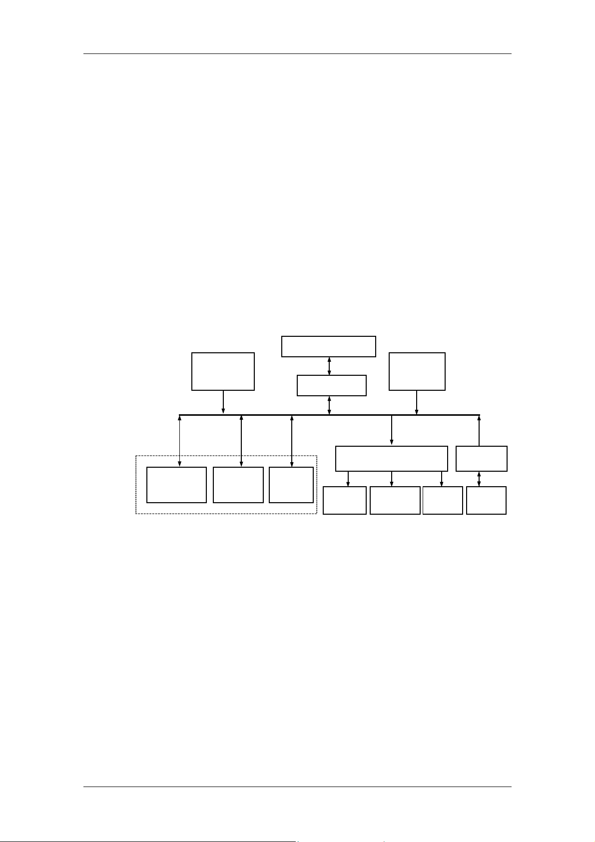
4.1 Main Control Board
The main control board is the control center of the whole hardware system. It
consists of the control circuits of 6 functional units (including main control unit,
photoelectric unit, reagent unit, sample unit, loading/mixing unit, temperature control
unit). Each functional unit has an MCU. They communicate in the multi-unit mode
and thus compose the whole control system.
ISE module
PC
Main control board
Step motors
DC motors
Pumps, valves
Level detection boards
Transducers
Power drive board
Heaters of reaction
disk
Reagent pre-heater
Lamp
Reagent
refrigeration board
Peltiers
transducers
The functions of the main control board are:
communicating with the PC through the RS232, receiving and analyzing
instructions from the PC and sending data to the PC.
controlling photoelectric conversion through the interface with the A/D conversion
board, reading and saving data from the A/D conversion board.
outputting control signals of each unit through the interface with the power drive
board.
4-1
Functions of Boards
receiving signals of fluid level detection and bump collision through the interface
with the level detection boards.
detecting signals from temperature transducers and controlling temperature of the
reaction disk and reagent preheating.
receiving signals from position transducers, deionized water transducer and waste
transducer and controlling the transducers.
controlling the built-in sample bar code scanner, reading the data and sending it to
the PC.
controlling the ISE module, reading the results and sending them to the PC.
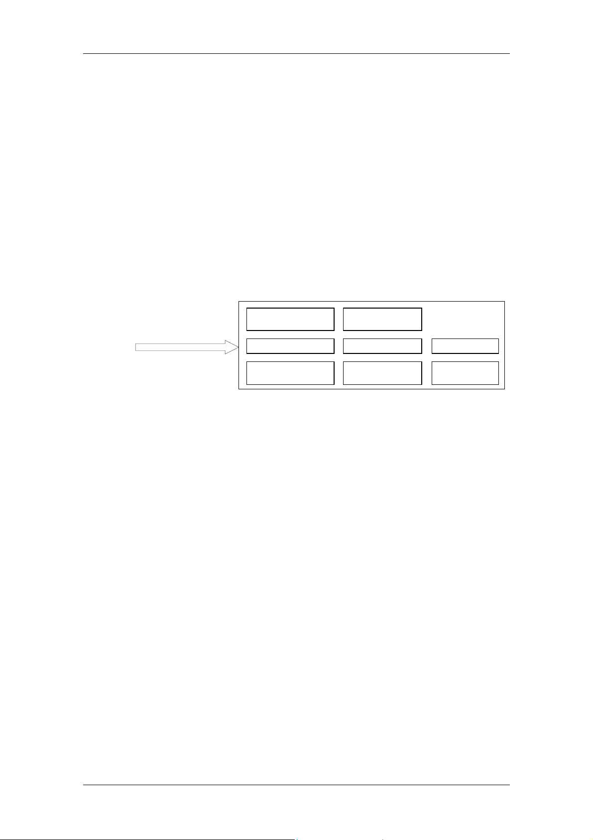
4.2 Power Drive Board
The main functions of the power drive board are to receive the control signals from
the main control board and control drive components. The block diagram of the
power drive board is shown in the figure below.
Control signals from
Main Control Board
to 13 step motors to 2 DC motors
to 2 solenoid valves to 3 pumps
to 2 heaters of
reaction disk
4.3 A/D Conversion Board
The 10 photoelectric conversion circuits convert the intensity signals of the lights
transmitting through the reaction cuvettes to electric signals, and then transmit them
to the A/D conversion board through a 5-core shielded cable. Photoelectric
conversion boards for different wavelengths have different gains and cannot be
replaced by each other.
The A/D conversion board filters and amplifies the 10 channels of electric signals
output from the photoelectric conversion boards, transmits them through the
multi-way gating switch to the A/D converter and then sends them to the main control
board for further processing.
to lamp power
to 2 magnets
to reagent
preheating
4.4 Reagent Refrigeration Board
The circuits of the reagent refrigeration board include the refrigeration circuit and the
fan circuit.
The refrigeration circuit is needed to work continuously, so it is powered separately.
The control objects of the reagent refrigeration board include:
Reagent refrigeration: 2 PELTIER components, 4 fans.
4-2
Heat sink system for the whole device: 3 lamp-cooling fans, 4 temperature control
fans of the reaction disk.
4.5 Level Detection Boards
The level detection boards that include sample level detection board and reagent
level detection board are used to detect the fluid level of sample and reagent
separately. When the analyzer aspirates reagents/samples, the probes dip into the
liquid to a specific depth, so as to avoid carryovers that have impacts on test results,
and to avoid air aspiration when the reagent/sample is insufficient.
4.6 Feeder Connection Board
The feeder connection board transfers the signals between the feeder transducer
and the main control board, and connects the power drive board and the loading
motor (DC).
Functions of Boards
Connections:
Connector Connected with
J91 Front transducer
J92 Back transducer
J93 Intermediate transducer
J94 No-cuvette transducer
J95 Pressure transducer
J96 Motor control wire (connected with the power drive board)
J97 Motor control wire (connected the motors)
J98 Cuvette-loading button
J99 Connection wire of the main control board
4.7 Manipulator Connection Board
The manipulator connection board transfers the signals between the manipulator
transducer and the main control board, and connects the power drive board and the
electromagnet.
Connections:
Connector Connected with
J101 Horizontal loading position transducer
J102 Vertical loading position transducer
J103 Electromagnet-closing transducer of the lower hand
4-3
Functions of Boards
Connector Connected with
J108 Electromagnet-closing transducer of the upper hand
J104 Drive wire of the electromagnet of the upper hand
J105 Drive wire of the electromagnet of the lower hand
J106 Drive wire of the electromagnet (connected with the power drive
board)
J107 Connection wire of the main control board
J109 Safeguard transducer (reserved)
J110 Safeguard transducer (reserved)
4.8 Probes Connection Board
The probes connection board transfers the signals between the sample/reagent level
detection board and the main control board, inputs the temperature signals, outputs
the reagent preheating signals, and transfers the signals between the power drive
board and the mixing motor (DC).
Connector Connected with
J200 Interface of the sample level detection board
J201 Interface of the reagent level detection board
J202 Interface of the mixing motor (DC)
J203 Sample detection signal interface of the main control board
J204 Reagent detection signal interface of the main control board
J205 Temperature control signal interface of the reaction disk
J206 Reagent preheating signal interface
J207 Interface of the power drive board
4.9 Power Supply Assembly
The power supply assembly consists of three boards: PFC board, 24V board,
12V&5V board and ISE (optional) power supply board.
The functions of the PFC board include:
AC/DC conversion;
Supplying the +390V and VDD voltage to the 24V board and the 12V&5V board;
Supplying stable 12V voltage for the lamp;
Supplying control signals of the analyzing unit switch to control the C12V, 5V and
24V outputs.
The 24V board converts the 390VDC current transmitted from the PFC board to the
separated 24VDC outputs through the forward converter.
4-4

Functions of Boards
The 12V&5V board converts the 390VDC voltage from the PFC board to B12V,
C12V and 5V voltages through the forward converter .
The ISE power supply board converts the 12V of the reagent refrigeration board to
24V that provides power supply for the ISE unit (optional).
4-5


5 Maintenance and Service
WARNING:
Before disassembling or assembling the analyzing unit, ensure the
POWER is placed to OFF.
The probe tip is sharp and can cause puncture wounds. To prevent
injury, exercise caution when working around the probe.
BIOHAZARD:
Wear gloves and lab coat and, if necessary, goggles.
Dispose of the waste in accordance with your local or national
guidelines for biohazard waste disposal.
CAUTION:
Please use Mindray-recommended consumables. Other consumables
may decrease the system performance.
Maintenance and Service
Refer to the BS-300 Chemistry Analyzer Operation Manual for details about
unclogging the sample probe
unclogging the reagent probe
replacing the sample probe
replacing the reagent probe
replacing the mixing bar
replacing the plunger assembly of syringe
replacing the lamp
5.1 Replacing Light Filter Assembly
The light filter and optical assembly are fixed in the supporting sleeve. The back end
is compacted and enclosed with the photoelectric amplification board and the screen
gland. Generally, the supporting sleeve is replaced together with the filter and optical
assembly.
5-1

Maintenance and Service
Figure 5-1 Light filter assembly
Gasket
Supporting Sleeve
Filter
Flat Spring
Lens
Lens Seat
Gasket
Screw
Photoelectric
Conversion Board
Shield Box
WARNING:
Before operating, ensure to place the POWER (main switch) to OFF.
1 Unscrew (counter clockwise) the two cap screws on the screen gland
whose wavelength is to be replaced.
2 Open the cover of the A/D conversion board, and unplug the plug
corresponding to certain wavelength.
5-2

Maintenance and Service
3 Take out the photoelectric conversion board and the supporting sleeve.
4 Keep the photoelectric conversion board upward, and loosen the two
retaining screws on it.
5 Keep the photoelectric conversion board upward, and pull the photoelectric
amplification board out of the supporting sleeve.
6 Unpack the new supporting sleeve containing the optical assembly. Be sure
to keep the top side (where to assemble the photoelectric amplification
board) of the supporting sleeve upward.
7 Install the original photoelectric conversion board onto the new supporting
sleeve, and then fasten the two retaining screws.
8 Install the screen gland, and fasten the retaining screws.
5-3

Maintenance and Service
9 Connect the photoelectric conversion board to the A/D conversion board,
and assemble the cover.
WARNING:
When replacing the light filter assembly, do not touch the optical
assembly in the supporting sleeve and the photoelectric receiving tube
of the photoelectric conversion board by hand.
The light filters and the photoelectric conversion boards are in
one-to-one relationship. Do not disarrange them.
5.2 Replacing Optical Fiber
WARNING:
Before operating, ensure to place the POWER (main switch) to OFF.
1 Unscrew the four screws on the supporting pillars of the cuvette feeder, and
remove the cuvette feeder.
5-4

Maintenance and Service
2 Unscrew the four screws on the reaction disk cover, and open the reaction
disk cover.
Attention should be paid to the power cable of the upper heater when the
reaction disk cover is being opened.
Power cable of
upper heater
3 Take out two cuvette segments in a diagonal with the needle-nose pliers to
make two spaces for disassemble the colorimetric disk.
4 Unscrew three M3 cap screws, and then disassemble the colorimetric disk.
5-5

Maintenance and Service
5 Use an M3 cap screwdriver to loosen the retaining screws of the optical
fibers on the colorimetric clamp and the reference light support.
6 T ake out the optical fibers one by one, and fix the optical component s in the
colorimetric clamp by fastening the screws slightly.
Screw of the reference light
7 Draw out all the nine optical fibers from the reaction compartment.
8 Loosen the M3 cap screw (used for retaining optical fibers) on the lamp
housing, and then draw out the optical fibers.
9 Put nine of the ten branches of the new optical fiber into the reaction disk
from its bottom one by one, loosen the retaining screw, insert the optical
fiber to the end, and then fasten the retaining screw.
10 Fix the reference light optical fiber.
5-6

Maintenance and Service
11 Fix the optical fiber of the lamp housing.
12 Put the colorimetric disk back and fix it.
13 Put the reaction disk cover back and fix it.
14 Install the cuvette feeder and fix it.
CAUTION:
When replacing the optical fiber, ensure that its bending radius is no
less than 20cm. Otherwise, the optical fiber will be damaged.
5.3 Adjusting Reaction Disk, Manipulator and Feeder
NOTE:
Debug the lower arm first (The relation between the lower arm position
and the reaction cuvette position is very important.), and then the upper
arm. When debugging the lower arm, move the cuvette compartment
aside.
1 Disassemble the cuvette feeder, and adjust the circular position of the
reaction disk (through the initial position transducer of the reaction disk) to
the standard position (The finger of the lower arm point s to the cen ter of the
slot between reaction cuvette segments).
2 Horizontally adjust the manipulator to the standard position (The finger of
the lower arm can work on reaction cuvettes well, and it should be 0.2mm
away from the nearest point of the reaction cuvette).
5-7

Maintenance and Service
3 Vertically adjust the manipulator the standard position (The finger of the
lower arm can work on reaction cuvette well, and the finger support of the
lower arm should be 0.15mm above the reaction cuvette.).
4 Run the manipulator to the position for taking new cuvettes, and
horizontally adjust the reaction cuvettes in the feeder. When catching a
cuvette, ensure a clearance of 0.4mm ~ 0.6mm between the finger of the
upper arm and the cuvette, and center them.
5.4 Adjusting Probes and Disks
NOTE:
Adjust the positions of the three probes and reaction cuvettes, and then
others.
Adjust the working position of the reagent probe (To minimize the
1
cumulative error, ensure that the reagent probe return to the initial position
before each adjustment.) as follows:
A For the reagent discharging position, ensure the reagent probe is in
the center of the reaction cuvette and the probe tin is 2 ~ 3mm away
from the bottom of the reaction cuvette.
B Adjust the position of the initial-position transducer of the reagent
disk. Ensure the mouths of reagent cuvettes in the inner and outer
circles fit the reagent disk cover well.
C Adjust the washing position of the reagent probe. Ensure the reagent
probe is in the center of the wash well and the probe pin is 5mm
away from the bottom of the wash well. If necessary, adjust the
position of the wash well.
D Adjust the reagent probe’s position on the outer circle of the reagent
disk. Ensure the reagent probe is in the center of the hole of the outer
circle.
5-8

Maintenance and Service
E Adjust the reagent probe’s position on the inner circle of the reagent
disk. Ensure the reagent probe is in the center of the hole of the inner
circle.
Adjust the working position of the sample probe (To minimize the
2
cumulative error, ensure that the sample probe return to the initial position
before each adjustment.) as follows:
A For the sample discharging position, ensure the sample probe is in
the center of the reaction cuvette and the probe tin is 2 ~ 3mm away
from the bottom of the reaction cuvette.
B Adjust the position of the initial-position transducer of the sample
disk. Ensure the mouths of sample cuvettes in the inner and outer
circles fit the reagent disk cover well.
C Adjust the washing position of the sample probe. Ensure the sample
probe is in the center of the wash well and the probe pin is 5mm
away from the bottom of the wash well. If necessary, adjust the
position of the wash well.
D Adjust the sample probe’s position on the outer circle of the sample
disk. Ensure the sample probe is in the center of the hole of the outer
circle.
E Adjust the sample probe’s position on the inner circle of the sample
disk. Ensure the sample probe is in the center of the hole of the inner
circle.
Adjust the working position of the mixing bar.
3
A Switch off the analyzing unit first, and then rotate the mixing arm to
see if its rotation radius is proper. If the mixing bar cannot reach the
center of the reaction cuvette, adjust the position of the mixing bar on
the mixing arm properly.
B Disassemble the mixing arm, and then switch on the analyzing unit to
run the reaction disk and stop it at any cuvette. Hold the mixing arm
by hand, and fix it at the center of the reaction cuvette.
C Vertically adjust the mixing bar’s position in the reaction cuvette.
Ensure the mixing bar tip is 1 ~ 2mm away from the bottom of the
reaction cuvette.
D Adjust the washing position of the mixing bar. Ensure the mixing bar
is in the center of the wash well and about 5mm away from the
bottom of the wash well. If necessary, adjust the position of the wash
well.
4 In the engineering adjustment software, select the Debug instruction
menu, and rotate the reaction disk for one lap. Dive probes and mix the
reactant at every position or every several positions to see if the three
probes interfere with any reaction cuvette (Command 61). If the mixing bar
knocks the side or the bottom of any cuvette, repeat Step 3.
5-9

Maintenance and Service
5.5 Replacing Components of ISE Unit (optional)
5.5.1 Replacing Tubing
NOTE:
(1) Fluidic tubing can be divided into the following six types.
W1 with two adapters connects the ISE module and the pump W.
Pump module
ISE module
Reagent module to be
placed here
Pump B Pump A
Pump tubing adapter
Pump tubing
Pump head
Pump W
Fluidic tubing adapter
W2 connects the reagent module and the pump W.
A1 (B1) with one adapter connects the sample entry port and the pump
A (pump B).
A2 (B2) with two adapters connects reagent module and the pump A
(pump B).
They are different in length and W1, A2 and B2 are not directional
when they are installed.
Usually the adapter has not been mounted to the fluidic tubing, so you
have to do it by hand. The tubing should be mounted to a short metallic
tube on the adapter. For convenience, the connectin g end of the tubing
can be dipped into hot water for several seconds.
(2) Pump tubing is used around a pump head. It has one adapter on
each end that makes connection with the fluidic tubing easy.
5-10

5.5.1.1 Replacing Fluidic Tubing W1 and W2
1 Place the POWER to OFF.
2 Open the ISE unit door.
3 If you want to replace the W1, unscrew the screw of the ISE module and
take off the cover.
4 Put out the fluidic tubing W2 and insert it into a container such as a cup that
is used to contain the waste solution flowing from the W2.
5 Start the analyzing unit and the system software.
6 Enter the ISE Maintenance screen of the system software.
7 Click the Maintenance button several times until there is no solution
flowing out from the W2.
8 Place the POWER to OFF.
9 If you want to replace W1, pull out its two adapters directly from the waste
pump tubing adapter and the right angle adapter that is fixed to the
compression plate.
Maintenance and Service
Right angle adapter
The side matches
the adapter of
fluid tubing W1
The side with a recess
matches the compressio n
plate of the ISE module.
Note that when pulling out the fluidic tubing adapter, in order not to release
the right angle adapter, you can hold the right angle adapter with a finger.
After that, install a new W1. For W2 exchange, it just needs to replace the
W2 with a new one.
10 If you want to replace the W2, replace it with a new one. Otherwise, insert
the W2 back to the reagent module.
11 Place the POWER to ON.
12 Enter the System Maintenance screen of the system software.
13 Select the Others tab and click the Download Settings button.
14 Enter the ISE Maintenance screen.
15 Click the A purge button to observe if there is solution leaking out. If there
is solution leaking out, repeat from the step 4 to install the tubing again.
16 Install the cover of the ISE module if it has been taken off.
17 Close the ISE unit door.
5-11

Maintenance and Service
5.5.1.2 Replacing Fluidic Tubing A1, A2, B1 and B2
1 Place the POWER to OFF.
2 T ake off the panel under the sample disk and you can see the shiel ding box
and the peristaltic pumps.
3 Open the ISE unit door.
4 Take out the reagent module.
5 Put the fluidic tubing W2 in a container such as a cup that is used to contain
the fluid flowing out from the W2.
6 Start the analyzing unit and the system software.
7 Enter the ISE Maintenance screen of the system software.
8 If you want to replace A1 or A2, click the A purge button. If you want to
replace B1 or B2, click the B purge button.
Repeat this step for several times until the received data indicates that the
Calibrant A or Calibrant B has air bubble in it.
9 Place the POWER to OFF.
10 Replace the tubing with a new one.
Note that before installing the A1 or B1 to the sample entry port, you can
dip the connecting end of the A1 or B1 into hot water for several minutes to
make the following procedures easily performed.
11 Start the analyzing unit.
12 If the system software is not running, start it. Otherwise, enter the System
Maintenance screen of the system software, select the Others tab and
click the Download Settings button.
13 Enter the ISE Maintenance screen of the system software.
14 If you have replaced A1 or A2, click the A purge button. If you have
replaced B1 or B2, click the B purge button.
Repeat this step for several times until the received data indicates that the
Calibrant A or Calibrant B has no air bubble in it.
5.5.1.3 Replacing Pump Tubing
1 Place the POWER to OFF.
2 Open the ISE unit door.
3 Pinch one adapter of the pump tubing and take it out from the tubing shelf.
Then take off the whole tubing.
Tubing shelf
5-12

4 Put one adapter of the new pump tubing onto the tubing shelf and make the
tubing around the pump ahead, then put the other adapter onto the shelf
with a little strength.
5 Start the analyzing unit and the system software.
6 Enter the ISE Maintenance screen.
7 Click the Pumps button to see if the calibration of pump is correct. If not,
repeat the upper steps.
5.5.2 Replacing Pumps
1 Place the POWER to OFF.
2 Take off the pump tubing around the pump head.
3 Disconnect the cable and the pump motor.
Maintenance and Service
4 Unscrew the four screws around the pump head.
5 Pull out the pump directly.
6 Put a new pump on the pump shelf, tighten the screws, connect the calbe
and pump motor, and then put the pump tubing around the pump head.
7 Start the analyzing unit and the system software.
8 Enter the ISE Maintenance screen.
9 Click the Pumps button to see if the calibration of pump is correct. If not,
repeat the upper steps.
5.5.3 Replacing ISE Module
Some times there is something wrong with the components in the ISE module such
as sample entry port, bubble detector, PCB and so on. In these cases, the ISE
module should be replaced according to the following procedure.
Cable
Pump motor
1 Place the POWER to OFF.
2 T ake off the panel under the sample disk and you can see the shiel ding box
and the pumps easily.
3 Open the ISE unit door.
4 Start the analyzing unit and the system software.
5 Enter the ISE Maintenance screen.
5-13

Maintenance and Service
6 Click the Maintenance button.
7 Place the POWER to OFF.
8 Unscrew the screw of the ISE module and take off the cover.
9 Take off all electrodes from above to below.
10 Disconnect the right angle adapter and the compression plate.
11 Disconnect the cable.
12 Unscrew the four screws that fix the ISE module to the shielding box. Then
take out the module from the shielding box.
13 Put a new ISE module to the shielding box. Then connect the cable and
install the electrodes sequentially. At last mount the right angle adapter to
the compression plate.
14 Install the electrodes sequentially.
15 Enter the System Maintenance screen of the system software.
16 Select the Others tab and click the Download Settings button.
17 Enter the ISE Maintenance screen.
18 Click the A pur ge button to see if there is solution leaking out. If there is,
take off the electrodes and install them again.
19 Check if the new ISE module can work normally.
5-14

6 Software Introduction
The software of BS-300 analyzer is composed of the system sof tware an d the control
software.
6.1 System Software
The system software can, according to the requirements and inputs of users,
generate a work schedule (instruction sequence), control the units of analyzing unit in
the sequence of instructions in the work schedule, receive photoelectric data,
response messages or execution results from the analyzing unit, output them to the
PC screen or the printer. With these outputs, users can obtain correct test results.
According to different functions, the entire PC softwa re system can be divided into the
following parts:
System Initialization
This part includes the initialization of the PC operating system, the initialization of the
communication between the PC and analyzing unit, and the controls of analyzing unit
reset.
Software Introduction
Control system
This part includes the formation of the work schedule, instruction data sending and
receiving.
GUI
This part includes the requests for tests (routine tests, emergency tests, calibration
tests and QC tests), the observation of test statu s (status of the reaction disk, sample
disk and reagent disk), test management, calibration management, QC manage ment,
result query, alarm management and the help system.
Shutdown Processing
This part includes the resets of sub-units.
6.1.1 System initialization
To initialize the PC operating system,
Check the PC operating system. The system software must run under Windows
2000 or Windows XP. Otherwise, the system will prompt that the system software
cannot run under other operating system, and then the system software system
exits automatically.
Check the current screen resolution for the operating system. The system software
must run under the resolution of 1024 × 768. Otherwise, the system prompts to
reset the resolution before restarting the system software and exit the system
software.
Disable the screen protection program. The system software must keep displayed
while running. To prevent the screen protection program from disturbing users in
the operating and observing processes, disable it.
Lock the keyboard. When running, the system software will lock some key
combinations to prevent users from starting any other program and condu cting any
6-1

Software Introduction
other operation. In this case, users cannot switch over to any other program or
print the current screen.
Check whether there is any username and password of the
maintenance/debugging personnel in the registry. The system software has the
debugging function. Only the authorized maintenance/debugging personnel can
enter the debugging window and maintain or debug the system and the host. For
the confidentiality, the username and password are saved in the registry. If they
are unavailable in the registry, the system will re-write the default username and
password into the registry.
To initialize the communication and the units auto-check,
Set serial ports and initialize them, including such parameters as the baud rate,
data bit, start bit, stop bit, parity bit, transmitting/receiving buffer, control protocol
and so on. In addition, start the serial port receiving thread.
Handshake for communication. Send a handshake instruction to the analyzing unit.
If the analyzing unit responds to this instruction (namely, send back a handshake
instruction to the PC), it indicates the PC handshakes with the host successfully. If
the host fails to respond to handshake instruction, it will re-send the handshake
instruction back in a specific period. If it fails for continuously three times, the
system will prompt to exit the system software. If you ignore that and continue to
enter the system software, all tests cannot be conducted under the system.
Check whether the printer is connected. If not, the system will prompt to connect it.
Send an instruction for querying the auto-check results of the units, check the
auto-check result of each unit. (The units are auto-checked when the analyzing
unit is started, and the auto-check results are stored in the main unit.) In case of
any fault data in the auto-check result of any unit, the system will prompt to switch
off the analyzing unit and check the faulty unit.
6.1.2 Shutdown processing
In the BS-300 Chemistry Analyzer Control System window, click the Exit button.
The Confirm dialog box appears. If you click OK, the system will
Switch off the lamp;
Unload all reaction cuvettes;
Wash the fluid tubing;
Reset all units;
Unlock the keyboard;
Prompt to exit the operating system and shut down the PC.
6.2 Control Software
The analyzing unit can be functionally divided into the following units: photoelectric
unit, reaction disk unit, reagent disk unit, sample disk unit, reagent probe syringe unit,
sample probe syringe unit, mixing bar unit, loading and manipulator unit, temperature
control unit, fluid tubing unit and reagent refrigeration unit. The functions of those
units are listed in the following table.
6-2

Software Introduction
Unit Function
Main unit Receives macroinstructions from the PC, decomposes them
into a series of action instructions, and then delivers the
action instructions to destination sub-units (in specific order)
at a certain interval.
Monitors the status of other units, and transmits data
collected by the photoelectric unit to the PC.
Photoelectric
unit
Reaction disk
unit
Reagent disk
unit
Sample disk
unit
Reagent probe
syringe unit
Photoelectrically detects, amplifies and converts the solution
in reaction cuvettes, and stores A/D converted data at the
twin port FIFO for the main unit to read and transmit them to
the PC.
Contains 80 cuvette No.
Runs the reaction cuvette with the specified No., following
the instruction of the main unit, to the reagent dispensing
position, sample dispensing position, mixing position, and
photoelectric detection position at all wavelengths.
Contains 50 bottle positions.
Carries reagents, and runs the reagent bottles with specified
No., following the instruction of the main unit, to the reagent
aspirating position.
Contains 60 tube positions in the inner and outer circles.
Carries samples, and runs the sample tubes with specified
No., following the instruction of the main unit, to the sample
aspirating position.
Receives instructions from the PC, and controls the reagent
probe in aspirating a specific volume of reagent from the
reagent bottle and dispensing it to the specified reaction
cuvette.
Sample probe
syringe unit
Mixing bar unit Receives instructions from the PC, and controls the mixing
Loading and
manipulator
unit
Receives instructions from the PC, and controls the sample
probe in aspirating a specific volume of sample from the
sample tube and dispensing it to the specified cuvette.
bar in mixing the solution in the cuvette that has been run to
the mixing position.
Runs the mixing bar to the wash well, and wash it after each
mixing process to avoid carryover.
Controls the cuvette feeder and manipulator.
The feeder assembly is responsible for detecting whether
there are enough reaction cuvettes in the cuvettes
compartment and pushing reaction cuvettes to the position
for the manipulator to take cuvettes.
The manipulator is responsible for taking reaction cuvettes
from the reaction disk, placing them into the used cuvette
bucket, taking new reaction cuvettes from the cuvette
compartment, and putting them on the reaction disk.
6-3

Software Introduction
Unit Function
Temperature
control unit
Fluid tubing unit Controls the fluid tubing in washing the reagent probe,
Controls the reaction disk temperature, reagent probe
preheating temperature and fluid tubing.
Note: The reaction disk temperature should be kept at 37 , ℃
the heating cavity of the reagent probe should be preheated
to 45 ℃.
sample probe and mixing bar.
Reagent
refrigeration
unit
Refrigerates the reagent chamber and controls its
temperature between 4 ~ 10 .℃
6-4

Service Flow
7 Service Flow
WARNING:
Before disassembling or assembling the analyzing unit, ensure the
POWER is placed to OFF.
The probe tip is sharp and can cause puncture wounds. To prevent
injury, exercise caution when working around the probe.
When you disassemble or replace any board, ensure to wear antistatic
gloves.
BIOHAZARD:
Wear gloves and lab coat and, if necessary, goggles.
7.1 Fluid Level Detection Failure of Reagent Probe
Surface
detection
failure of
reagent
probe(Th
e reagent
probe
does not
detect
the
surface
on the
reaction
disk.)
The
reagent
probe
cannot
detect
the
surface
on the
reagent
disk
Surface detection signal transmission error: The surface detection
board does not have the working voltage, or when the probe touches
the surface, the indicator of the surface detection board is normal, but
there is always a host alarm indicating surface detection failure.
Possible cause: The patch cord for the reagent surface detection is
disconnected, or the connector is not well connected.
Surface detection signal processing error: When the probe touches
the surface, the indicator of the surface detection board is normal, the
connection between the main control board and the surface detection
board is normal, and no surface detection signal reaches the main
control board, but there is always a host alarm indicating surface
detection failure.
The surface
detection
signal fails
to be
generated
by
capacitance
change.
Possible cause: Main control board.
Power failure: The working voltage of the surface
detection board is 12V. In case of no power supply, the
surface detection signal cannot be generated.
Possible cause: Disconnection; the connector is not well
connected; there is no 12V out put from t he main cont rol
board.
Probe failure: The detection terminal has a changeable
capacitance. Loose exterior or interior of the probe, the
sealing-off of the probe connecting wire and the probe
breakage will result in unsteady voltage or obvious
voltage changes. In this case, the capacitance signal
will be unavailable or exceed the range of the surface
detection board.
Possible cause: Reagent probe assembly, connector.
Surface detection board failure: When there is no probe
failure, but the indicator is always on, or the indicator is
not on when the probe touches the surface, there must
be a surface detection board failure.
Troubleshooting: Replace the surface detection board.
The
reagent
probe mis-
detected
the surface
When this failure occurs, the sample probe cannot detect
the surface at the reaction disk, but there is no alarm at
the reagent unit. For details, see Surface Detection
Failure: Sample Probe.
7-1

Service Flow
7.2 Fluid Level Detection Failure of Sample Probe
No reagent in the reaction disk: The reagent probe misdetects the surface, aspirates air and dispenses into the
reaction cuvette. Therefore, the reagent unit CPU fails to
make any judgment. In this case, the sample probe cannot
detect the surface when dispensing the sample into this
The sample
probe cannot
detect the
surface at the
reaction disk.
reaction cuvette.
Possible cause: Surface detection failure of the reagent probe
insufficient reagent: The reagent probe aspirates less reagent
than the set volume. As a result, the sample probe cannot
detect the surface at the preset height.
Possible cause: The reagent is prepared in the bottle, the
reagent syringe is not fixed, leakage occurs in the tubing of
the reagent probe, or there are bubbles in the reagent.
Position correction parameter error of the sample probe: In
case of such an error, the sample probe cannot reach the
surface in the steps.
Troubleshooting: Re-correct the sample probe position.
Surface
detection
failure of
the
sample
probe
The sample
probe cannot
detect the
surface at the
reaction disk.
The sample
probe misdetects the
surface (In
this case,
there will be
no alarm, but
test results
will become
abnormal. On
the reaction
curve, you
can see that
no sample is
added.)
Surface detection signal transmission failure: When the probe
touches the surface and stops, the indicator of the surface
detection board is on for about 2 seconds. The output signal
of the surface detection board switche s normally, but there is
always a host alarm indicating that no surface is dete cted.
Possible cause: The patch cord for detecting the sample
surface is disconnected, or the connector is not well
connected.
Signal processing failure of the main control board: When the
probe touches the surface, the indicator works normally. But
there is always a host alarm indicating that no surface is
detected. Ensure that the sample surface detection signal is
transmitted to the relevant connector of the main control
board.
Possible cause: Main control board failure
Surface detection signal failure: The indicator of the surface
detection board is not on or always on when the sample
probe touches the surface.
Surface mis-detection at the sample d isk: In this case, there
will be no alarm, but the sample probe fails to aspirate the
sample, and the test result and reaction curve become
abnormal.
Possible cause: Sample probe, surface detection board,
surface detection patch cord.
Surface mis-detection at the reaction disk: In this case, there
will be no alarm, but there is residual sample on the sample
probe tip, and drops on the table when the probe leaves the
reaction disk.
Possible cause: The sub-unit software is later than V1.7, or
the sample probe is not in the center of the reaction cuvette.
7-2

7.3 Liquid Dropping From Probes
Drips drop from the sample probe
due to fluid tubing leakage. In this
case, there will be liquid dropping
onto the table widely, and there may
be liquid dropping even when the
sample probe is static.
Troubleshootin
g for the liquid
dropping from
the reagent
probe and
sample probe.
Drips drop from the sample probe
due to surface detection failures. In
this case, most liquid drop on the
area between the reaction disk and
the wash well.
Service Flow
Tubing leakage due to the abraded syringe
piston
Troubleshooting: Replace the syringe or the
syringe piston
The reagent probe takes liquid from the
reaction disk.
The reagent probe did not detect the surface at
the reaction disk, and dispenses the reagent at
the corresponding height. If the reagent probe
cannot touch the surface at the position for
dispensing reagent, the last reagent drop will
be taken out by the reagent probe.
Possible cause: The probe arm is installed at a
too high position; the position of the sample
probe has not been corrected; the syringe is
loose; there are bubbles in the reagent bottle.
The sample probe takes liquid from the reaction
disk.
The sample probe detects the surface and
stops immediately. Then it dispenses the
sample at 1mm under the surface. If the
reagent probe mis-detects the surface, the
dispensed sample will fail to be added into the
reagent, but taken at the probe tip and drops
when the probe is moving. As a result, some
test results become abnormal.
Possible cause: There are bubbles in the
reaction cuvette; the sample probe is not in the
center of the reaction cuvette, and its position
has not been corrected.
Other failures
Drips taken from the reagent disk or sample
disk and dropping from probes
Such failures are usually followed by alarms
indicating that no surface is detected at the
reagent/sample disk. The reagent/sample
probe does not aspirate reagent/sample, but
the reagent/sample probe will stretch out to the
bottom of the reagent bottle/sample tube due to
surface detection failures. As a result, reagent/
sample liquid will be taken on the exterior of
the probe and drop while the probe is moving.
Probe being bent
Troubleshooting: Replace the probe.
Smudges on the sample probe absorb some
liquid and drop it while the probe is moving.
Troubleshooting: Cleaning the sample probe.
Probe driving assemblies are not assembled
well, resulting in probe jittering and liquid
dropping in the vertical movements.
Troubleshooting: Adjust or replace the probe
driving assemblies.
7-3

Service Flow
7.4 Failing to Detect Level of Water for Washing Exteriors
Surface detection signal failure:
See relevant resolutions for the
surface detection failure.
No water in the wash water tank: Users
can see this failure in the alarm
information detergen t em pty. In case of
no alarm information, check whether
Failing to
Detect the
Surface of
the Water
for
Washing
Exteriors
there is any problem in the detergent tank
Pump damaged: In this case, there will
be no water in the three wash wells.
Troubleshooting: Replace the pump.
No water in the
wash well
Tubing blocked: In this case, there will be
insufficient water for washing exteriors,
the three water flows are no t the same, or
there will be no water in any of the three
wash wells.
Possible cause: The unidirectional valve
is blocked, or the detergent entrance is
cover assembly.
blocked.
Reagent or sample probe.
Solution: Replace a probe
The tube is disconnected.
Possible cause: The tube is degraded, or
other causes.
Troubleshooting: Connect the tubes
again.
7-4

7.5 Abnormal Results
7.5.1 All Results Being Abnormal
All results are
lower than
normal
results.
All test
results are
abnormal
Some results
are higher,
and some are
lower, with
bad
repeatability.
Service Flow
No sample or insufficient sample is added.
In this case, it can be seen on the reaction curve that
the absorbance has not increased in the period for
adding the sample. The reaction curve is even, and
many results are 0.
Possible cause: Sample probe blocked, tubing
leakage, syringe not fixed, valve not shut tightly.
The reaction is not thorough.
If the sample is not mixed uniformly with the reagent,
the reaction will not be thorough, and the light cannot
detect the changes of the absorbance.
Possible cause: The mixing bar did not mix the
reacting liquid.
The volumes of dispensed sample are not the same.
In this case, it can be seen from the reaction curve
that the response is proportional to the volume of the
sample.
Possible cause: Tubing leakage, valve not shut
tightly, or cuvette segments not cleaned well.
7.5.2 Some Results Being Abnormal
Good repeatability
Bad repeatability
Observe the reaction curve, and find the possible
Some test results are
abnormal.
All test results are approaching to 0.
Observe the reaction curve first.
Possible cause: The lamp base of corresponding
wavelength exceeds 65535; the photoelectric
detection unit fails to detect the change of
absorbance, reagent failure and optical fiber
disconnection.
Troubleshooting: Re-calibrate it.
causes.
7-5

Service Flow
7.5.3 Several Results Being Abnormal
Several test results are too low.
In this case, observe the reaction curve first.
Possible cause: Drips dropping from the sample
Several test results are
abnormal
Several test results suddenly become too high.
In this case, observe the reaction curve first.
Possible cause: There are bubbles in the current
cuvette; the mixing bar knocks the cuvettes.
probe
7-6

7.6 Insufficient Light Intensity of Lamp
Insufficient Light
Intensity of the Lamp
Record the lamp background value and gain
Measure and record the lamp background value and gain
Service Flow
Lamp background values of all
channels decreases.
Estimate whether the
lamp has worked for
2000h (lifetime),
replace Lamb
S
E
Y
Adjust the gain parameter to make the
lamp base AD values of all channel
lamps increase to about 62000.
Remove the fault alarm
YES
Lamp base values of several
channels decreases
Replace lamb
Replace the lamp.
Check whether the AD value of the
channel whose lamp vase value is
smaller increases obviously.
Replace the lamp with
the original lamp
Replace the photoelectric transducer
assembly, and then check whether the
lamp base value increases obviously.
YES
Replace the
photoelectric
transducer assembly.
Replace the optical
fiber
YES
NO
NO
Change the positions with the
smaller fiber end, and check
whether the lamp base value
increases obviously.
O
N
Check whether the photometric
system (such as the lens)
Clean the
photometric system
(such as the lens)
corresponding to the fiber channel
YES
is covered with dirt or the like. (If
yes, clean it.) Then check whether
the lamp base value increases
obviously
Note:
Do not adjust the photoelectric gain parameter in case you have no idea about the
cause for the alarm indicating insufficient light intensity of the lamp.
7-7

Service Flow
7.7 Temperature Control Failure
Temperature control failure
Query and record the
fault log codes and
descriptions.
Monitor the temperature
curve.
Obtain the current
temperature control
parameter, and check
whether it is the same as the
factory parameter.
Replace the
temperature
transducer.
Replace the heating
assembly.
NO
N
Enable and disable the
temperature control function
repeatedly for 2 ~ 3 times
Check whether the temperature
transducer is normal.
yes
O
Check whether the heating
resistance is normal.
S
E
Y
Restart the analyzer and then
check whether it is normal.
To monitor the temperature curve
1
A In the BS-300 Chemistry Analyzer Control System window, select
the [System/Temperature] menu. A dialog box appears. Enter
BS300DEBUG and MINDRAY respectively in the User Name and
Password text boxes. Then click OK to enter the Temperature
Control Curve window.
B Set a proper temperature range for observing the change of the
temperature curve, and then click the Start button.
7-8

C Minimize the Temperature Control Curve window for future
observation at any time.
D After that, print or snap the temperature curve and then return it to
the headquarters together with the service work report.
To measure the impedance of the temperature transducer
2
A Switch off the BS-300 analyzer.
B Open the left side plate of the BS-300 analyzing unit to expose the
main control board.
C Unplug J45 (reagent preheating temperature transducer), and
measure the resistance between PIN1 and PIN3 with a multimeter.
The relation between the resistance and the temperature is: 25℃
/1100Ω, 38.5℃/1145Ω, 45℃/1170Ω, 50℃/1170Ω.
D Unplug J44 (reaction disk temperature transducer), and measure the
resistance between PIN1 and PIN3 with a multimeter. The relation
between the resistance and the temperature is: 25℃/1100Ω, 38.5℃
/1145Ω, 45℃/1170Ω, 50℃/1170Ω.
To measure the resistance of the heater
3
Service Flow
A Measure the impedance of the reagent preheater in the following
procedures:
Unplug J24 (power driving board)
Measure the impedance between PIN1 and PIN2. Reagent preheater
(BA30-10-06626)/24.6 to 28.5Ω.
B Measure the impedances of the upper and lower heaters of the
reaction disk in the following procedures:
Disconnect the connecting wire from J113 of the power patching
board.
Measure the impedances of the upper and lower heater: upper
temperature-sensitive heater (BA30-10-06624)/437.8 to 483.8Ω,
lower temperature-sensitive heater (BA30-10-06625)/131.4 to
145.2Ω.
7.8 Bar Code Scanner (optional) Failure
WARNING:
Light sent by the bar code scanner may hurt your eyes. Do not stare
into the laser beam from the bar code scanner.
If the bar code scanner cannot emit laser , you can service it according to the fol lowing
steps.
1 Place sample tubes with bar code labels that meet the requirements
mentioned in the operation manual.
2 Restart the analyzer.
7-9

Service Flow
3 Enter the Scanner Setup & Maintenance screen of the system software.
4 Enter the Maintenance tab.
5 Enter the sample position range in the Sample Position field and click the
If the bar code scanner emits laser normally but is failed in reading, you can service it
according to the following steps.
1 Place the ANALYZING UNIT POWER to OFF.
2 Place sample tubes with bar code labels that meet the requirements
3 See if the window on the sample department is stained. If so, clean the
4 Restart the analyzer.
5 Enter the Scanner Setup & Maintenance screen of the system software.
Step Scan button. Observe if the scanner can emit laser. If not, click the
Laser on button. If the scanner still cannot emit laser, go to the next step.
mentioned in the operation manual.
window with absolute alcohol-dipped gauze and go to the next step. If not,
go to the step 8.
6 Enter the Maintenance tab.
7 Enter the sample position range in the Sample Position field and click the
Step Scan button. Observe the scanning procedures to see if the scanner
can read the bar codes. If not, go to the next step.
8 Enter the Setup tab.
9 Select all symbologies but do not select any Check or Length.
10 Enter the Maintenance tab.
11 Click the Scan button to see if the scanner can read the bar codes. If not,
go to the next step.
12 Place the test fixture to the position 28 on the sample disk.
13 Click the Mechanism button at the System Maintenance screen to reset
all mechanical parts. If the laser from the scanner cannot reach the bar
code through the slit on the test fixture, adjust the screws on the brackets
until the laser from the scanner can reach the bar code.
7-10
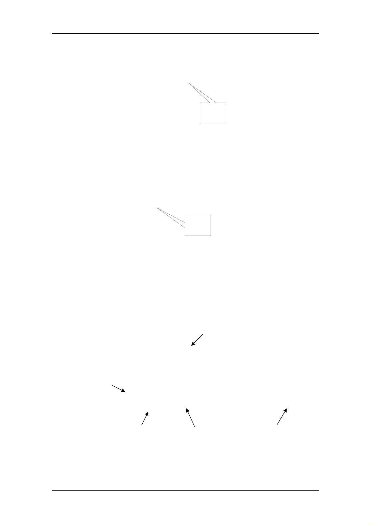
Bracket 1
Service Flow
Bracket 2
14 If the scanner cannot read the bar cod es successfully, replace the bar code
scanner. If the new scanner cannot read the bar code, you need to check
the bar code labels the user used.
7.9 Feeder Failure
7.9.1 Transducer Distribution of the Feeder
Pressure Transducer
No-Cuvette
Transducer
Cuvette-Pushing
Limit Transducer
Insufficient-Cuvette
Transducer
7-11
Cuvette-taking limit
transducer

Service Flow
7.9.2 Feeder Failure
Feeder failure
symptom
The trolley moves
backward to the
end, but does not
move forward.
Possible causes:
The trolley moves
forward and stops
before compacting
the cuvette
segment
1. The cuvette-taking limit signal has not been
detected.
2. The belt is too tight, so the motor cannot run.
Troubleshooting:
1. Check whether the voltage is 0 when the
cuvette-taking limit optical coupler is blocked.
2. Adjust the position of the motor to loosen the
belt.
1. The moving resistance is too large, so the
trolley fails to compact the cuvette segment, but
the pressure transducer has been blocked.
2. The sliding block falls off, resulting in large
friction.
3. The motor cannot work normally.
4. The belt is too tight.
Troubleshooting:
1. Clean the guiding axis of the trolley.
2. Replace the sliding block assembly.
3. Replace the motor.
4. Loosen the belt.
The trolley keeps
moving backward
and forward
1. The no-cuvette transducer has not been
pressed completely, so the system deems that
the cuvette compartment is empty, and the
trolley moves back for cuvette segments.
Troubleshooting:
1. Adjust the position of the no-cuvette
transducer.
2. Replace the feeder assemblies.
7-12

7.9.3 Manipulator Failure
Manipulator vertical-
movement error:
Cannot reach/leave the
initial position.
The signal of the vertical optical coupler
has not been detected after the motor
runs for specified steps.
Possible causes:
1. The resistance of the lead screw is too
large (frequently).
2. The optical couplers for the vertical
initial position cannot work (scarcely).
3. The vertical motor of the manipulator
cannot work (scarcely).
4. The optical coupler connector is not
connected well (infrequently).
5. The power driving board cannot work
(infrequently).
6. The main control board cannot work
(scarcely).
Service Flow
Troubleshooting:
1. Lubricate the
lead screw after
cleaning it.
2. Replace
relevant
assemblies.
Manipulator
Failure
The upper hand of the
manipulator cannot
close/open.
Direct cause:
The finger signal has
not been detected after
the electromagnet of
the manipulator is
switched on.
The lower hand of the
manipulator cannot
close/open.
Direct cause:
The finger signal has
not been detected after
the electromagnet of
the manipulator is
switched on.
The upper/lower hand
of the manipulator
accidentally closes/
opens.
Direct cause:
After the manipulator is
switched on, the finger
coupler signal is
received, but the signal
changes suddenly
while the manipulator
is moving.
1. The snap ring of the manipulator is not
flexible (infrequently).
2. The coupler of the upper finger cannot
work any more (scarcely).
3. The upper hand of the manipulator is
not arranged well with the position of the
feeder/reaction disk (frequently).
4. The coupler connector is not
connected well (infrequently).
1. The operator has added too many
cuvette segments into the feeder (behind
the trolley). When the trolley moves
backward, the jaw is pressed back by the
cuvette segments; when it moves forward
again, the hand fails to open in time, so
the jaw may press one side of the trolley
only. As a result, the cuvette segment at
the front fails to corporate with the upper
hand of the manipulator well (frequently).
2. The lower hand of the manipulator fails
to corporate with the reaction disk
position well (frequently).
3. The snap ring of the manipulator is not
flexible (infrequently).
4. The lower hand coupler of the
manipulator cannot work any more
(scarcely).
1. The snap ring of the manipulator is not
flexible (frequently).
2. The finger coupler of the manipulator
cannot work any more (scarcely).
1. Adjust the
positions of the
upper hand and
the feeder/
reaction disk.
2. Replace the
manipulator (Its
position must be
adjusted).
1. Press the
cuvette-taking
key after adding
cuvette
segments into
the feeder.
2. Adjust the
positions of the
lower hand and
reaction disk.
3. Replace the
manipulator (Its
position must be
adjusted)
Troubleshooting:
1. Replace the
manipulator (Its
position must be
adjusted).
7.10 Troubleshooting of ISE Unit (optional)
When there is something wrong with the ISE unit, an error code will be displayed at
the screen and saved in the log. The error code of the ISE unit has a format of 7
ASCII characters, the format of which is <1234567>.
Each digit represents a certain error.
Digit 1: Air in sample, Calibrant A, Calibrant B, Bubble Detector, mV range.
Digit 2: Sample/Calibrant B mV range.
7-13

Service Flow
Digit 3: mV out of range for Calibrant A in Sample Cycle, or Calibrant B in Urine
Digit 4: Noise in mV of Calibrant B in Calibration Cycle, or Sample mV during a
Digit 5: mV Noise in Calibrant A of the Calibration Cycle, or Sample Cycle, mV
Digit 6: mV Drift of calibrant A.
Digit 7: Slope of Sample value is out of range.
Each row represents where the error locates in.
You can find all the seven numbers in the table below digit by digit and then know
what is wrong with the ISE unit. 0 means no error.
For example, when you see <0001000>, you only need to find where the “1” locates
in the Digit 4 column and you will see it locates in the Na+ row. So you will know the
cause of this error is the noise in mV of Calibrant B or sample related to the Na
electrode.
Cycle.
Sample Cycle.
Noise in Calibrant B of the Urine Cycle.
+
Error
Digit 1 Digit 2 Digit 3 Digit 4 Digit 5 Digit 6 Digit 7
Air/
Hardwa
re
mV Out
Calib/S
ample
mV Out
Cal A in
Calib/S
ample
Mode,
Cal B in
Urine
Mode
mV
Noise
Cal
B/Samp
le
mV
Noise
Cal A in
Calib/S
ample
Mode,
Cal B in
Urine
Cal A
Drift
in
Sample
Mode,
Cal B in
Urine
Mode
Out of
Slope/
Machin
e
Ranges
Mode
Air in
S 0 0 0 0 0 0
Sample/Urine
Air in Calibrant A A 0 0 0 0 0 0
Air in Calibrant B B 0 0 0 0 0 0
Air in Cleaner C 0 0 0 0 0 0
Air in Segment M 0 0 0 0 0 0
Pump Calibration P 0 0 0 0 0 0
No Flow F 0 0 0 0 0 0
Bubble Detector D 0 0 0 0 0 0
Reagent Chip
R 0 0 0 0 0 0
Read
Reagent Chip
W 0 0 0 0 0 0
Write
Store Calibration
Q 0 0 0 0 0 0
Value Error
Command Error T 0 0 0 0 0 0
No Error 0 0 0 0 0 0 0
Na+ 0 1 1 1 1 1 1
7-14

Service Flow
Digit 1 Digit 2 Digit 3 Digit 4 Digit 5 Digit 6 Digit 7 Error
Air/
Hardwa
re
K+ 0 2 2 2 2 2 2
Na+, K+ 0 3 3 3 3 3 3
Li+ 0 4 4 4 4 4 4
Li+, Na+ 0 5 5 5 5 5 5
Li+, K+ 0 6 6 6 6 6 6
Li+, K+, Na+ 0 7 7 7 7 7 7
Cl- 0 8 8 8 8 8 8
mV Out
Calib/S
ample
mV Out
Cal A in
Calib/S
ample
Mode,
Cal B in
Urine
Mode
mV
Noise
Cal
B/Samp
le
mV
Noise
Cal A in
Calib/S
ample
Mode,
Cal B in
Urine
Mode
Cal A
Drift
in
Sample
Mode,
Cal B in
Urine
Mode
Out of
Slope/
Machin
e
Ranges
Cl-, Na+ 0 9 9 9 9 9 9
Cl-, K+ 0 A A A A A A
Cl-, Li+ 0 B B B B B B
Cl-, K+, Na+ 0 C C C C C C
Cl-, Li+, Na+ 0 D D D D D D
Cl-, Li+, K+ 0 E E E E E E
Cl-, Li+, K+, Na+ 0 F F F F F F
The following table displays the causes and the correction measures of some errors.
Note that if the correction measure is the replacement of board, bubble detector or
other components in the ISE unit, you have to replace the whole ISE unit. You can
refer to the chapter 5 for detailed information about some replacement procedures.
Symptom Problem Correction
System does not
respond
1. No power
2. Communication failure Turn off the system and then
start it again.
3. RS232 cable is disconnected
or damaged.
4. Module connector has been
damaged.
5. Component failure on board. Replace board.
Move the panel of analyzing unit
and reconnect or replace cable
between the ISE unit and the
main control board.
Replace board.
7-15

Service Flow
Symptom Problem Correction
Low Slope
Na+, K+, or Li+ <45
mV/decade
Cl- <35 mV/decade
or
High Slope
Na+, K+, or Li+ >63
mV/decade
Cl- >60 mV/decade
Noise Error Flag
Single electrode
1. Misalignment of electrodes Remove and replace electrodes
<45 mV/decade to reseat
properly.
2. Deterioration of calibrator
solutions
3. Deterioration of sensing
electrode (low slope)
4. Air bubble on reference
electrode membrane
5. Deterioration of reference
electrode
6. Module or fluid temperatures
exceed 37° C. (high slope)
1. Deterioration of sensing
electrode
2. Electrical noise spike from
environmental source
Replace Calibrant B first and
retest. If still low, replace
Calibrant A and retest.
Replace problem electrodes
and test.
Remove electrode, tap to
dislodge bubble, replace, and
recalibrate.
Replace reference electrode
and retest.
Monitor temperature. Change
instrument location if ambient is
too great.
Replace problem electrodes
and test.
a) Check for electrical noise
coincident with activation.
Noise Error Flag
Multiple electrodes
Drift Error Flag
Single electrode
Drift Error Flag
Multiple electrodes
1. Deterioration of reference
electrode
2. Electrical noise spike from
environmental source
1. May occur when new
electrode or new bottle of
Calibrant A is installed by
system.
2. Deterioration of sensing
electrode
1. May occur when new
electrode or new bottle of
Calibrant A is installed on
system.
b) Check grounding of Module.
c) Component failure on Module
board. Replace board.
Replace reference electrode
and retest.
a) Check for electrical noise
coincident with activation.
b) Check grounding of Module.
c) Component failure on Module
board. Replace board.
Purge the Calibrant A and
recalibrate the module. If the
electrode is new it may initially
drift as it rehydrates over the
course of 15 minutes.
Replace the problem electrode
and test.
Purge Calibrant A and
recalibrate the Module.
2. Deterioration of reference
electrode.
7-16
Replace reference electrode
and retest.

Symptom Problem Correction
Service Flow
3. Electrical spike from
environmental source.
Air in Sample
Air in Sample and
Calibrant A
1. Insufficient sample pipetted
into Module sample entry port
2. Sample not positioned a) Electrodes not seated
1. Sample and Calibrant A are
segmented with air.
a) Check for electrical noise
coincident with activation.
b) Check grounding of Module.
c) Component failure on Module
board. Replace the board.
a) Host instrument must deliver
70 µL. Increase dispensed
volume.
b) Operator must place
sufficient sample in sample cup
to account for all tests
programmed.
c) Fluid leak in electrodes.
properly. Reseat electrodes.
b) Pump tubing aging. Replace.
c) Pump tubing obstructed or
tubing length is excessive.
a) Electrodes are not properly
seated or compressed. Check
compression plate, spring and
seal. Reseat electrodes.
Air in Calibrant B and
Air in Calibrant A
b) Ensure that all electrodes
and o-rings are in place.
2. Fibrin or salt is plugging the
electrode flow path.
3. Bubble detector is
malfunctioning.
4.Waste pump is
malfunctioning.
1. Calibrant B and Calibrant A
are segmented with air.
a) Use Cleaning procedure for
Module.
b) Disassemble Module and
clean or replace electrode with
plugged flow path.
Replace bubble detector.
Replace waste pump.
a) Electrodes are not properly
compressed. Check
compression plate, spring and
seal.
b) Ensure that all electrodes
and o-rings are in place.
c) Ensure tubing is connected
properly.
d) Replace tubing.
7-17

Service Flow
Symptom Problem Correction
Air in Calibrant A (no
“Air” errors reported for
Sample or Calibrant B)
2. Fibrin or salt is plugging the
electrode flow path.
3. Waste pump malfunction. Replace waste pump, tubing.
4. Bubble Detector malfunction. Replace bubble detector.
1. Calibrant A pouch is empty. Replace Calibrant A with a new
2. Tubing is disconnected. Reconnect or replace tubing.
3. Calibrant A pump is not
working properly.
4. Tubing is plugged, split or
crimped.
a) Use Cleaning procedure for
Module.
b) Disassemble Module and
clean or replace electrode with
plugged flow path.
one, purge and recalibrate.
a) Check electrical connections.
b) Replace pump tubing.
c) Replace motor.
Replace tubing
7-18

8 Mechanical Structure
Synchronous belts
Coder sensors
Mechanical Structure
Reaction disk motor Reagent disk motor
8-1

Mechanical Structure
Reagent probe assembly
Sample probe assemblyMixing bar assembly
Reagent cooling assembly
8-2

Lamb assembly
Mechanical Structure
Big head of fiber
Fan of Lamb assembly
8-3

Mechanical Structure
Optical assembly
Reaction disk TEMP.
control assembly
Small heads of fiber
Reference light assembly
8-4

Mechanical Structure
p
V
Reagent syringe
Washing assemblies
Sam
le syringe
alves
Pumps
8-5

Mechanical Structure
A/D conversion board
Main control board Power drive board
Reagent refrigeration board
8-6

Mechanical Structure
Loading system
Manipulator
assembly
8-7

Mechanical Structure
Top of mixing assembly
Top of sample assembly
Top of reagent assembly
Bar code scanner (optional)
8-8

Tools and Parts
9 Tools and Parts
9.1 Service Tools
S/N TOOL Quantity Specification Unit
1 Allen Key 1 set 1.5, 2.0, 2.5, 3.0, 3.5,
4.0, 5.0
2 Phillips screwdriver 1 set 3*75, 5*75, 6*100 mm
3 Flat-bladed screwdriver 1 set 3*75, 5*75, 6*100 mm
4 Long Allen Key 1 set 2.5, 3.0 mm
5 Tweezers 1 pair small /
6 Multimeter 1 common /
7 Movable Wrench 1 common /
mm
8 Electric iron 1 30 VA
9 Stainless steel 1 0.5 (diameter), 15
(length)
10 Knife 1 common /
11 Pincers 1 common /
9.2 Parts
S/N P/N Name
1 BA30-20-06448 Cable for reagent probe assembly’s elevator motor
2 BA30-20-06449 Cable for reagent probe assembly’s rotary motor
3 BA30-20-06450 Cable for Sample syringe’s motor
4 BA34-20-63601 Cable for Reagent syringe’s motor
5 BA30-20-06452 Cable for sample probe assembly’s elevator motor
6 BA30-20-06453 Cable for sample probe assembly’s rotary motor
7 BA30-20-06454 Cable for mixing bar assembly’s rotary motor
mm
8 BA30-20-06455 Cable for mixing bar assembly’s elevator motor
9 BA30-20-06458 Cable for reagent compartment motor
10 BA30-20-06459 Cable for sample compartment motor
11 BA34-20-63602 Cable for reaction compartment motor
12 BA30-20-06464 Cable for loading system motor
13 BA30-20-06468 Cable for Sample and reagent valves
9-1

Tools and Parts
S/N P/N Name
14 BA30-20-06476 26-pins sensor cable
15 BA30-20-06477 34-pins sensor cable
16 BA30-20-06480 Detection cable for reaction compartment’s fan
17 BA30-20-06481 Cable between CPU board and power drive board
18 BA30-20-06484 Cable for waste and distill water container
19 BA30-20-06485 Cable between CPU board and loading system
20 BA34-20-63651 Cable between CPU board and manipulator
21 BA30-20-06523 T emperature sensor cable of reagent cooling system
22 BA30-20-15291 Cable between CPU board and reagent detection board
23 BA30-20-15292 Cable between CPU board and sample detection board
24 BA34-20-63603 Cable between power drive board and mixing motor
25 BA34-20-63631 Reagent probe cable
26 BA30-20-15295 Sample probe cable
27 BA30-20-15296 Mixing bar cable
28 A21-000010--- Tubing
29 BA30-10-15051 Single-way valve
30 0040-10-32303 Tubing
31 0040-10-32304 Connector
32 0040-10-32305 Connector
33 M90-100014--- 1/4-28 UNF LOCK NUT-RED NYL LNS-3
34 M90-100015--- 1/4-28 UNF LOCK NUT-RED N NYL LNS-4
35 M90-100030--- 1/8 Y BARBED FITTING-WHITE NYL Y23036
M90-100050---
37
M90-100051--38 M90-100071--- Tubing
39 BA30-30-15169 5-way connector
40 BA30-10-06666 Step motor
BULKHEAD MOUNTED FEMALE LURE RED NYLON
CCLR-3
BULKHEAD MOUNTED FEMALE LURE GREEN NYLON
CCLR-4
41 BA30-10-15041 synchronous belt (220 XL037)
42 BA30-10-15258 Door’s magnet (couple)
43 BA34-30-63559 Power drive board
44 BA30-30-06312 Reagent cooling control board
45 BA34-30-63613 Sample compartment assembly
9-2

Tools and Parts
S/N P/N Name
46 BA30-10-06365 Halogen Lamb (50W)
47 BA30-30-06691 REF pre-amplification board
48 BA30-30-15228 340nm amplification assembly
49 BA30-10-06367 Filter 340
50 BA30-30-06673 340nm pre-amplification board
51 BA30-30-15229 405nm pre-amplification assembly
52 BA30-10-06368 Filter 405
53 BA30-30-06675 405 pre-amplification board
54 BA30-30-15230 450nm pre-amplification assembly
55 BA30-10-06369 Filter 450
56 BA30-30-06677 450 pre-amplification board
57 BA30-30-15231 510nm pre-amplification assembly
58 BA30-10-06370 Filter 510
59 BA30-30-06679 510 pre-amplification board
60 BA30-30-15232 546nm pre-amplification assembly
61 BA30-10-06371 Filter 546
62 BA30-30-06681 546 pre-amplification board
63 BA30-30-15233 578nm pre-amplification assembly
64 BA30-10-06372 Filter 578
65 BA30-30-06683 578 pre-amplification board
66 BA30-30-15234 630nm pre-amplification assembly
67 BA30-10-06373 Filter 630
68 BA30-30-15235 630 pre-amplification board
69 BA30-30-15235 670nm pre-amplification assembly
70 BA30-10-06374 Filter 670
71 BA30-30-06687 670 pre-amplification board
72 BA30-30-15236 700nm pre-amplification assembly
73 BA30-10-06375 Filter 700
74 BA30-30-06689 700 pre-amplification board
75 BA30-30-06565 Drive assembly of sample probe
76 BA34-30-63637 Syringe assemply
77 3100-10-49438 100ul Syringe
78 BA30-10-06651 500ul Syringe
79 BA30-10-15115 Step motor
9-3

Tools and Parts
S/N P/N Name
80 BA30-20-06594 3-way connector for syringe
81 BA30-21-15161 Sensor cable for reagent syringe
82 BA30-21-15162 Sensor cable for sample syringe
83 BA30-30-06634 Mixing bar assembly
84 BA30-21-15159 Cable for mixing bar assembly’s elevator motor
85 BA30-21-15160 Cable for mixing bar assembly’s rotary motor
86 BA30-30-06639 Fans of lamb assembly
87 BA30-30-06641 Washing pool assembly
88 0040-10-32302 Connector
89 0040-10-32303 Washer
90 BA30-21-15311 Valves assembly (KNF)
91 BA30-30-06702 Reaction compartment assembly
92 BA30-30-06715 A/D converter assembly
93 BA30-30-06752 Rocker of reagent probe
94 BA30-30-06304 Liquid detection board
95 BA30-30-06753 Reagent probe assembly
96 BA30-30-06761 Heat-block assembly
97 BA30-30-06768 Rocker of sample probe
98 BA30-30-14978 Sample probe assembly
99 BA30-30-06770 Rocker of mixing bar
100 BA34-20-63653 Loading system assembly
101 BA30-21-06488 Pressure sensor and cable for loading system
102 BA30-21-06490 Cable for cuvette-pushing limit transducer
103 BA30-21-06491 Cable for cuvette-taking limit transducer
104 BA30-21-06492 Cable for insufficient-cuvette transducer
105 BA34-20-63648 Board for loading system
106 BA30-21-06489 Cable for no-cuvette transducer
107 BA30-30-15034 Code sensor of reaction compartment
108 BA30-30-15095 Reagent compartment assembly
109 BA30-30-06780 Reagent disk handle assembly
110 BA30-30-15113 Driving assembly of reagent probe
111 BA30-21-15155 Sensor cable for reagent probe’s up-down sensor
112 BA30-21-15156 Sensor cable for reagent probe’s rotary sensor
113 BA30-30-15166 Coder sensor for reagent disk
9-4

Tools and Parts
S/N P/N Name
114 BA30-30-15167 Coder sensor for sample probe’s sensor
115 BA30-30-15284 Probes connection board
116 BA34-30-63557 Main control board
117 BA33-30-35098 Power supply module
118 BA33-30-35078 PFC Board
119 BA33-30-35082 24V Board
120 BA33-30-35080 12V&5V Board
121 TSB1-20-20399 Fan
122 BA34-20-63655 Manipulator assembly
123 BA33-30-35223 Power socket and switch assembly
124 BA34-20-63622 Reagent temperature control assemply (220V)
125 BA34-20-63614 Cover of sample compartment
126 BA30-30-15029 Cover of reagent compartment
127 BA34-20-63638 Reagent temperature control assemply (110V)
9-5


Maintenance And T est Software
10 Maintenance And Test Software
10.1 General
The maintenance and test software of the BS-300 Chemistry Analyzer is the
software that helps maintenance personnel debug and maintain the BS-300
Chemistry Analyzer. Maintenance personnel can, through this software, check
whether the probes, mixing bar, disks, fluidic system and photometric system of
the BS-300 Chemistry Analyzer work normally, modify parameters, and execute
individual commands or combined commands.
Run the NewDebug.exe file to enter the Maintenance and Test window. See
Figure 10-1.
Figure 10-1 Maintenance and Test window
Display Area
As shown in Figure 10-1, there are 4 tabs in the Maintenance and Test window:
Command
PARA and Speed
Temperature
Photoelectric
10-1

Maintenance And T est Software
Note:
The buttons displayed in gray in software interface are not
functional.
Following is a brief introduction to the software interface.
Display area
At the bottom of the window is the display area for displaying the frame
information and fault/error information. The upper box is for frame information, and
the lower one is for fault/error information.
There are five types of frame information, including Result, Echo, Data,
Command and Warning.
Select the check box in front of frame information to display relevant frame
information. Click the check box again to de-select, and the frame information will
not be displayed.
Click the Clear button to clear the information displayed in relevant box. The two
Clear buttons are respectively for two boxes.
Setup button
Click the Setup button at up right corner to show a dialog as shown in Figure 10-2,
which is used to change communication port and set baud rate and check sum
type of the port. Check sum type includes odd, even and none.
Figure 10-2 Serial Port Setup
Communication Port
Baud Rate
Check Sum Type
About… button
Clicking the About… button at up right corner of the interface, you can view the
version information of this software.
In the following sections, the 4 tabs mentioned above will be detailed respectively.
10-2

Note:
The units of parameters involved in this software are respectively:
Time: 50ms;
Sample (reagent) aspirating/dispensing volume: steps of motors;
Temperature: ℃.
Temperature control coefficient: 0.01.
10.2 Command
In the Command tab, you can send commands to the analyzing unit and check
whether probes, mixing bar, disks, fluidic system, photometric system, ISE unit
and built-in bar code scanner work normally.
Figure 10-3 Command tab
Maintenance And T est Software
Single Command Area
As shown in Figure 10-3, the Command tab mainly consists of two parts: Single
Command Area and Macroinstruction Area.
Macroinstruction Area
10.2.1 Single Command Area
In Single Command Area, there are 8 sub-tabs:
Main Unit
Reagent Unit
Sample Unit
10-3

Maintenance And T est Software
Load Unit
Temp Unit
Photoelectric Unit
ISE Module
Sample Bar Code Module
Check the analyzing unit for their counterparts.
There are several buttons in each tab. Click a button and you can send a
command to the counterpart on the analyzing unit.
Note:
After starting this software, you must click the Download
parameters to Analyzing Unit button in the Main Unit sub-tab.
Otherwise, the software will not operate the analyzing unit
successfully.
After clicking the Enable modifying parameters button in the Main
Unit sub-tab, you can modify the parameters in the PARA and
Speed tab.
Following are instructions to the action implemented by each command.
Main Unit
Command What it does
Download parameters to
Analyzing Unit
Reset all mechanical parts Moves all units of the analyzing unit to their
Enable modifying
parameters
Disable modifying
parameters
Handshake with Analyzing
Unit
Send a direct instruction Edits and sends user-defined commands.
Configures running parameters for the
analyzing unit.
initial position, and cleans reagent probe,
sample probe and mixing bar.
Switches on the switch for modifying parameter
through this operation before modifying
parameter at PARA and Speed tab.
Switches off the switch for modifying parameter
through this operation after modifying
parameter at PARA and Speed tab.
Checks that the communication cable works
normally.
Reagent Unit
Command What it does
Reagent probe wash Cleans the reagent probe.
Pump, valve (interior) on Turns on the pump and the valves that control
flow of washing the interior of reagent probe.
10-4

Maintenance And T est Software
Command What it does
Pump, valve (interior) off Turns off the pump and the valves that control
flow of washing the interior of reagent probe.
Pump, valve (exterior) on Turns on the pump and the valve that control
flow of washing the exterior of reagent probe.
Pump, valve (exterior) off Turns off the pump and the valve that control
flow of washing the exterior of reagent probe.
Probe above reaction disk Moves the reagent probe above the reaction
disk.
Probe above outer circle Moves the reagent probe above the outer circle
of reagent disk.
Probe above inner circle Moves the reagent probe above the inner circle
of reagent disk.
Probe tip above bottle top
(outer circle)
Probe tip above bottle top
(inner circle)
Probe down to outer circle Moves the reagent probe down to the reagent
Probe down to inner circle Moves the reagent probe down to the reagent
Probe down to reaction disk Moves the reagent probe down to the cuvette
Probe tip above cuvette top Moves the reagent probe until the probe tip a
Probe down to wash well Moves the reagent probe to its washing
Probe above wash well Moves the reagent probe to the top of wash
Reagent disk rotate Rotates the reagent disk for specified circles
Moves the reagent probe until the probe tip a
few millimeters above the top of the reagent
bottle in the outer circle of reagent disk.
Moves the reagent probe until the probe tip a
few millimeters above the top of the reagent
bottle in the inner circle of reagent disk.
bottle in the outer circle of reagent disk.
bottle in the inner circle reagent disk.
in the reaction disk.
few millimeters above the top of cuvette in the
reaction disk.
position.
well.
and stop it at specified bottle position. Input
rotating circles in the first box and position No.
in the second box.
Reagent disk rotate to
position
Reagent syringe init Moves the reagent syringe to its initial position.
Reagent syringe full Moves the reagent syringe to its largest travel.
Reagent syringe empty Empties the reagent syringe.
Reagent unit reset Cleans the reagent probe and rotates the
Rotates the reagent disk to specified bottle
position. Input position No. in the box.
reagent disk to position No. 1.
10-5

Maintenance And T est Software
Sample Unit
Command What it does
Sample probe wash Cleans the sample probe.
Pump, valve (interior) on Turns on the pump and the valves that control
Pump, valve (interior) off Turns off the pump and the valves that control
Pump, valve (exterior) on Turns on the pump and the valve that control
Pump, valve (exterior) off Turns off the pump and the valve that control
Probe above wash well Moves the sample probe to the top of wash
Probe above reaction disk Moves the sample probe to the top of reaction
Probe above outer circle Moves the sample probe above the outer circle
flow of washing the interior of sample probe.
flow of washing the interior of sample probe.
flow of washing the exterior of sample probe.
flow of washing the exterior of sample probe.
well.
disk.
of sample disk.
Probe above inner circle Moves the sample probe above the inner circle
of sample disk.
Probe tip above tube top
(outer circle)
Probe tip above tube top
(inner circle)
Probe tip above cuvette top Moves the sample probe until the probe tip a
Probe down to reaction disk Moves the sample probe down to the reaction
Probe down to wash well Moves the sample probe to its washing
Probe down to outer circle Moves the sample probe down to the tube in
Probe down to inner circle Moves the sample probe down to the tube in
Sample disk rotate Rotates the sample disk for specified circles
Moves the sample probe until the probe tip a
few millimeters above the top of the tube in the
outer circle of sample disk.
Moves the sample probe until the probe tip a
few millimeters above the top of the tube in the
inner circle of sample disk.
few millimeters above the top of cuvette in the
reaction disk.
cuvette in reaction disk.
position.
the outer circle of sample disk.
the inner circle of sample disk.
and stop it at specified tube position. Input
rotating circles in the first box and position No.
in the second box.
Sample disk rotate to
position
Sample syringe init Moves the sample syringe to its initial position.
Sample syringe empty Empties the sample syringe.
Sample syringe full Moves the sample syringe to its largest travel.
Rotates the sample disk to specified tube
position. Input position No. in the box.
10-6

Maintenance And T est Software
Command What it does
Sample unit reset Cleans the sample probe and rotate the sample
disk to position No. 1.
Load Unit
Command What it does
Mixer to the top of wash well Moves the mixing bar to the top of wash well.
Mixer move into wash well Moves the mixing bar to its washing position.
Mixer move to the top of
reaction disk
Mixer move into reaction
disk
Mixer stir for a while Mixing bar stirs for a specified period.
Mixing bar rotates for a while
above wash well
Take new cuvettes Moves the compartment trolley backwards to
Load New cup Rotates the reaction disk to specified position,
Unload cup Rotates the reaction disk to specified position,
Motion of manipulator fingers Tightens or loosen manipulator’s fingers
Moves the mixing bar to the top of reaction
disk.
Moves the mixing bar to mixing position in
reaction disk.
Moves the mixing bar above its wash well and
then rotates it for a specified period.
get new cuvettes.
then get new cuvettes with the manipulator and
put them in reaction disk.
then get the cuvettes in reaction disk with the
manipulator and put them in used-cuvette
bucket.
(grabbing mechanism).
After entering a value of 0-3 to the box, click
the button and the fingers will motions. 0
means both fingers tighten; 1 means the upper
loosen and the lower tightens; 2 means the
upper tightens and the lower loosens; and 3
means both loosen.
Manipulator to vertical init.
pos.
Manipulator to horiz. init.
pos.
To H-pos. for taking cuvettes Moves the manipulator to horizontal position for
To V-pos. for taking cuvettes Moves the manipulator to vertical position for
To H-position for placing
cuvettes
To V-position for placing
cuvettes
Moves the manipulator to vertical initial
position.
Moves the manipulator to horizontal initial
position.
getting cuvettes.
getting cuvettes.
Moves the manipulator to horizontal position for
placing cuvettes.
Moves the manipulator to vertical position for
placing cuvettes.
10-7

Maintenance And T est Software
Command What it does
Move steps vertically Moves the manipulator for specified steps in
Move steps horizontally Moves the manipulator for specified steps in
Loader unit reset Moves the mixing bar to its initial position,
Temp Unit
Command What it does
Temperature control on Turns on the specified temperature
vertical way.
horizontal way.
loosen manipulator’ grabbing mechanism and
move the manipulator to its initial position.
controller(s).
There’re two temperature controllers as
Reaction Disk and Reagent PreHeat.
Selects the check box(es) in front of a
controller(s), click the button, you can turn on
the selected controller(s).
Temperature control off Turns off the specified temperature
controller(s).
There’re two temperature controllers as
Reaction Disk and Reagent PreHeat.
Selects the check box(es) in front of a
controller(s), click the button, you can turn off
the selected controller(s).
Photoelectric Unit
Command What it does
Reaction disk rotate Rotates the reaction disk for specified circles
and stop it at specified cuvette position. Input
rotating circles in the first box and position No.
in the second box.
Reaction disk rotate some
positions
Rotate and measure Rotates the reaction disk, collects reaction data
Rotates the reaction disk for specified cuvette
positions, and input number of cuvette
positions in the box.
during rotating, and then stops it at specified
cuvette position.
Turn on light Turns on the light.
Turn off light Turns off the light.
Test dark current Turns off the light and measures the dark
current at this time. The dark current data will
be displayed in the box below.
10-8

Maintenance And T est Software
Command What it does
Test base current Unloads the first segment of cuvettes in
reaction disk with manipulator, then rotates the
reaction disk and during rotating measures the
light where places the first segment of cuvettes
before. The data regarding base current will be
displayed in the box below.
ISE Module
Command What it does
Handshake The ISE unit shakes hands with the main unit.
Maintain Executes the maintaining cycle to run the waste pump until
the electrode flow path is cleared of fluid.
Detect Bubble Checks to see if the bubble detector is functioning
properly.
Cleaning Period Removes protein build-up from the ISE Module electrodes.
Calibrate Calibrates the electrodes of the ISE Module.
Correct Pumps Calibrates the peristaltic pumps of the ISE Module.
Measure Serum Measures serum or plasma samples on the ISE Module.
A Purge Purges Calibrant A solution through the tubing from the
pouch of Calibrant A to the ISE Module.
B Purge Purges Calibrant B solution through the tubing from the
pouch of Calibrant B to the ISE Module.
<DSPA> Pumps 200µl of Calibrant A to make it convenient for you
to aspirate it from the sample entry port.
<SWBC> Displays the result of bubble detector checking for the last
time.
<SWPC> Displays the result of pump correction for the last time.
<CKSM> Displays the software version of the ISE unit.
<DVON> After clicking this button, the results in mv will also be
displayed when calibration, measurement or a sip cycle is
finished.
<MVON> After clicking this button, the results in mv will also be
displayed when calibration or measurement is finished.
<DVFF> Disables the effect of clicking <DVON> or <MVON>.
Sample Bar Code Module
Command What it does
Set Select a symbology from the pull down list and click this
button. If Valid is selected, the symbology will be set as the
one that the scanner can recognize. Otherwise, it will be
the one that can not be recognized.
10-9

Maintenance And T est Software
Command What it does
Send Enter an instruction into the edit box and click this button to
send it to the analyzing unit.
Laser On Turns on the laser of the bar code scanner.
Laser Off Turns off the laser of the bar code scanner.
Handshake The bar code scanner shakes hands with the main unit.
Scan After entering the start position No. and the end one into
Start and End edit boxes respectively, click this button to
scan bar codes on the selected positions.
10.2.2 Macroinstruction Area
Figure 10-4 Macroinstruction Area
Button
Parameters of the
current command
Explanation for the
macroinstruction
Macroinstruction
Commands
A macroinstruction is a set of commands.
When selecting a macroinstruction from the pulldown list in macroinstruction area,
you can see there’re various commands and comments regarding the
macroinstruction. In addition, parameters of the command currently selected will
also be displayed on the interface.
In the macroinstruction area, after selecting a macroinstruction from the pulldown
list, you can
Click the Run button to run the selected macroinstruction;
10-10

Maintenance And T est Software
Click the Pause button to suspend the macroinstruction which is running;
Click the Stop button to stop the macroinstruction which is running.
Note:
After all commands in each macroinstruction are executed, the
system counts it as one time.
When the check box on the right of the macroinstruction pulldown
list is selected, the selected macroinstruction will be executed for
once; otherwise, the macroinstruction will be executed cyclically.
For each macroinstruction, the commands of it are executed one by one in the
sequence in which they are listed. When the set delay expires after a command is
executed, the next command is executed immediately. In case of an error in the
execution process, the macroinstruction will be stopped.
Following are instructions to the action implemented by each macroinstruction.
Macroinstruction Command What it does
A,B purge
B purge Purges Calibrant B solution
through the tubing from the
pouch of Calibrant B to the
ISE Module.
Check exterior fluid
path of reagent
probe
Check exterior fluid
path of sample
probe
A purge Purges Calibrant A solution
through the tubing from the
pouch of Calibrant A to the
ISE Module.
Reagent probe above
wash well
Valve on, Pump on Turns on the pump and valve
Pump off, Valve off Turns off the pump and valve
Sample probe above
wash well
Valve on, Pump on Turns on the pump and valve
Pump off, Valve off Turns off the pump and valve
Moves the reagent probe
above its wash well.
that control the flow of
washing the exterior of
reagent probe.
that control the flow of
washing the exterior of
reagent probe.
Moves the sample probe
above its wash well.
that control the flow of
washing the exterior of
sample probe.
that control the flow of
washing the exterior of
sample probe.
10-11

Maintenance And T est Software
Macroinstruction Command What it does
Check interior fluid
path of reagent
probe
Reagent probe above
wash well
Valve on, Pump on Turns on the pump and
Pump off, Valve off Turns off the pump and
Moves the reagent probe
above its wash well.
valves that control the flow of
washing the interior of
reagent probe.
valves that control the flow of
washing the interior of
reagent probe.
Check interior fluid
path of sample
probe
Test Loader Reload cup looply The manipulator gets new
Test mixing bar in
reaction disk
Sample probe above
wash well
Valve on, Pump on Turns on the pump and
Pump off, Valve off Turns off the pump and
Reaction disk to next
cup
Mix instruction The mixing bar moves into
Mixer to vertical init The mixing bar moves to
Moves the sample probe
above its wash well.
valves that control the flow of
washing the interior of
sample probe.
valves that control the flow of
washing the interior of
sample probe.
cuvettes from the
compartment looply, and then
put them in the reaction disk.
The reaction disk rotates and
stops. No. of position for
reaction disk to stop at will
increase.
reaction cuvette and mixes
for a specified period.
vertical initial position.
Test reagent probe
in reaction disk
Test sample probe in
reaction disk
Reaction disk to next
cup
Reagent probe to
reaction disk
Reagent probe to
vertical init
Reaction disk to next
cup
10-12
The reaction disk rotates and
stops. No. of position for
reaction disk to stop at will
increase.
The reagent probe moves
vertically into bottom of
reaction cuvette.
The reagent probe moves to
vertical initial position.
The reaction disk rotates and
stops. No. of position for
reaction disk to stop at will
increase.

Maintenance And T est Software
Macroinstruction Command What it does
Sample probe to
reaction disk
The sample probe moves
vertically into bottom of
reaction cuvette.
Urine test (auto
diluted)
Sample probe to
vertical init
Reagent disk in
position 50 in next
period
Dispensing 270µl of
urine diluent
Dispensing 30µl of
urine sample
Washing mixing bar Washes the mixing bar.
First period Sample probe aspirates 70µl
Second period Sample probe aspirates 70µl
The sample probe moves to
vertical initial position.
Reagent disk rotates to
position 50 and in the next
period the reagent probe will
aspirate urine diluent from the
position.
Reagent probe aspirates
207µl of urine diluent and
dispenses it to a cuvette.
Sample probe aspirates 30µl
of urine sample and
dispenses it to a cuvette. The
mixing bar stirs it.
of diluted urine to the ISE
unit.
of diluted urine to the ISE
unit.
Urine test (manually
diluted)
10.3 PARA and Speed
Third period Washes the sample probe.
Idle period Measuring.
Idle period Measuring.
Idle period Measuring.
First period Sample probe aspirates 70µl
of diluted urine to the ISE
unit.
Second period Sample probe aspirates 70µl
of diluted urine to the ISE
unit.
Third period Washes the sample probe.
Idle period Measuring.
Idle period Measuring.
Idle period Measuring.
In the PARA and Speed tab, you can query, configure or load parameters as well
as debug the units.
10-13

Maintenance And T est Software
Figure 10-5 PARA and Speed tab
Parameters
As shown in Figure 10-5, the PARA and Speed tab mainly consists of two parts as
unit parameter and several operating buttons.
Buttons
Unit Name includes Main unit, Sample unit, Reagent unit, Photoelectric unit,
Temp unit and Load unit.
At this screen, you can not only inquire and configure each unit parameters, but
also save and read relevant data. Now let’s introduce them respectively.
Inquire unit parameters
1 Select a unit in Unit Name.
2 Click Query button.
For example.
10-14

Maintenance And T est Software
Configure a parameter for a unit
1 Select a unit in Unit Name.
2 Click the Query button.
3 Edit the parameter if necessary. Otherwise, go to the next step directly.
When editing, you can directly select and modify the data to be edited.
4 Select a parameter to be configured. For example.
5 Click the Config button to configure the parameter for relevant unit of the
analyzing unit.
Configure all parameters for relevant units
1 Select units in Unit Name.
2 Click the Config All button to configure all parameters of the selected unit
for relevant units of the analyzing unit.
Save data
1 Select a unit in Unit Name.
2 Click the Save button, then pop up a dialog.
3 Input a filename and click the Save button, you can save parameters of the
currently selected unit to a .txt file.
Read Data
1 Click Load button, then pop up a dialog.
2 Select the relevant .txt file and click Open button, you can configure
parameters in the file for relevant unit of the analyzing unit.
The following contents explain the adjustable parameters.
10-15

Maintenance And T est Software
Reagent unit
Parameter Unit Default What the parameter m eans
H-pos. for washing
reagent probe
Whole
step
42 Position correction of the
reagent probe in the horizontal
direction when it is above its
wash well.
H-pos. of reaction disk Whole
step
H-pos. of reagent disk
inner circle
H-pos. of reagent disk
outer circle
Position correction of
reagent disk inner circle
Position correction of
reagent disk outer circle
Whole
step
Whole
step
Micro
step
Micro
step
-42 Position correction of the
reagent probe in the horizontal
direction when it is above the
reaction disk.
215 Position correction of the
reagent probe in the horizontal
direction when it is above the
inner circle of reagent disk.
165 Position correction of the
reagent probe in the horizontal
direction when it is above the
outer circle of reagent disk.
10 The position correction of the
reagent disk when it stops at
the specified position according
to the position No. of its inner
circle.
10 The position correction of the
reagent disk when it stops at
the specified position according
to the position No. of its outer
circle.
Sample unit
Parameter Unit Default What the parameter means
Bar code position
correction of sample
disk inner circle
H-pos. for washing
sample probe
H-pos. of sample disk
inner circle
H-pos. of sample disk
outer circle
Micro
step
Whole
step
Whole
step
Whole
step
18 Position correction of the inner
circle of sample disk relative to
the outer circle when the bar
code scanner scans specified
positions.
102 Position correction of the
sample probe in the horizontal
direction when it is above its
wash well.
202 Position correction of the
sample probe in the horizontal
direction when it is above the
inner circle of sample disk.
165 Position correction of the
sample probe in the horizontal
direction when it is above the
outer circle of sample disk.
10-16

Maintenance And T est Software
Parameter Unit Default What the parameter means
H-pos. of sample probe
in reaction disk
Whole
step
-106 Position correction of the
sample probe in the horizontal
direction when it is above the
reaction disk.
H-pos. of sample probe
in ISE
Position correction of
sample disk inner circle
Position correction of
sample disk outer circle
V-pos. of sample probe
in ISE
Whole
step
Micro
step
Micro
step
Whole
step
490 Position correction of the
sample probe in the horizontal
direction when it is above the
sample entry port of ISE unit.
10 The position correction of the
sample disk when it stops at
the specified position according
to the position No. of its inner
circle.
10 The position correction of the
sample disk when it stops at
the specified position according
to the position No. of its outer
circle.
163 Position correction of the
sample probe in the vertical
direction when it is above the
sample entry port of ISE unit.
Load unit
Parameter Unit Default What the parameter means
Manipulator h-position
for placing cuvettes
Whole
step
70 Position correction of the
manipulator in horizontal
direction when it places a
cuvette segment into the
reaction disk.
Manipulator h-position
for taking cuvettes
Manipulator v-position
for placing cuvettes
Manipulator v-position
for taking cuvettes
Mixing bar h-position
for washing
Whole
step
Whole
step
Whole
step
Whole
step
259 Position correction of the
manipulator in horizontal
direction when it takes a
cuvette segment from the
cuvette compartment.
70 Position correction of the
manipulator in vertical direction
when it places a cuvette
segment into the reaction disk.
768 Position correction of the
manipulator in vertical direction
when it takes a cuvette
segment from the cuvette
compartment.
68 Position correction of the
mixing bar in the horizontal
direction when it is above its
wash well.
10-17

Maintenance And T est Software
Parameter Unit Default What the parameter means
Mixing bar h-position
for mixing
Photoelectric unit
Parameter Unit Default What the parameter means
Photoelectric gain
parameter 405
Whole
step
/ 127 Signal gain coefficient of A/D
70 Position correction of the
mixing bar in horizontal
direction when it is above the
reaction disk.
conversion for wavelength of
405nm.
Photoelectric gain
parameter 450
Photoelectric gain
parameter 510
Photoelectric gain
parameter 546
Photoelectric gain
parameter 578
Photoelectric gain
parameter 630
Photoelectric gain
parameter 670
Photoelectric gain
parameter 700
/ 127 Signal gain coefficient of A/D
/ 127 Signal gain coefficient of A/D
/ 127 Signal gain coefficient of A/D
/ 127 Signal gain coefficient of A/D
/ 127 Signal gain coefficient of A/D
/ 127 Signal gain coefficient of A/D
/ 127 Signal gain coefficient of A/D
conversion for wavelength of
450nm.
conversion for wavelength of
510nm.
conversion for wavelength of
546nm.
conversion for wavelength of
578nm.
conversion for wavelength of
630nm.
conversion for wavelength of
670nm.
conversion for wavelength of
700nm.
Photoelectric gain
parameter reference
light
Photoelectric gain
parameter 340
Start position of
photoelectric collection
/ 127 Signal gain coefficient of A/D
/ 127 Signal gain coefficient of A/D
Micro
step
conversion for wavelength of
reference light.
conversion for wavelength of
340nm.
25 Correction of the start position
when photoelectric collection
starts.
10-18
 Loading...